US6032752A - Vehicle suspension system with variable geometry - Google Patents
Vehicle suspension system with variable geometry Download PDFInfo
- Publication number
- US6032752A US6032752A US08/853,442 US85344297A US6032752A US 6032752 A US6032752 A US 6032752A US 85344297 A US85344297 A US 85344297A US 6032752 A US6032752 A US 6032752A
- Authority
- US
- United States
- Prior art keywords
- biasing
- vehicle
- slide rail
- dampening
- chassis
- Prior art date
- Legal status (The legal status is an assumption and is not a legal conclusion. Google has not performed a legal analysis and makes no representation as to the accuracy of the status listed.)
- Expired - Fee Related
Links
Images
Classifications
-
- B—PERFORMING OPERATIONS; TRANSPORTING
- B60—VEHICLES IN GENERAL
- B60G—VEHICLE SUSPENSION ARRANGEMENTS
- B60G15/00—Resilient suspensions characterised by arrangement, location or type of combined spring and vibration damper, e.g. telescopic type
- B60G15/02—Resilient suspensions characterised by arrangement, location or type of combined spring and vibration damper, e.g. telescopic type having mechanical spring
- B60G15/06—Resilient suspensions characterised by arrangement, location or type of combined spring and vibration damper, e.g. telescopic type having mechanical spring and fluid damper
-
- B—PERFORMING OPERATIONS; TRANSPORTING
- B60—VEHICLES IN GENERAL
- B60G—VEHICLE SUSPENSION ARRANGEMENTS
- B60G13/00—Resilient suspensions characterised by arrangement, location or type of vibration dampers
- B60G13/001—Arrangements for attachment of dampers
- B60G13/005—Arrangements for attachment of dampers characterised by the mounting on the axle or suspension arm of the damper unit
-
- B—PERFORMING OPERATIONS; TRANSPORTING
- B60—VEHICLES IN GENERAL
- B60G—VEHICLE SUSPENSION ARRANGEMENTS
- B60G2204/00—Indexing codes related to suspensions per se or to auxiliary parts
- B60G2204/10—Mounting of suspension elements
- B60G2204/12—Mounting of springs or dampers
- B60G2204/129—Damper mount on wheel suspension or knuckle
-
- B—PERFORMING OPERATIONS; TRANSPORTING
- B60—VEHICLES IN GENERAL
- B60G—VEHICLE SUSPENSION ARRANGEMENTS
- B60G2204/00—Indexing codes related to suspensions per se or to auxiliary parts
- B60G2204/40—Auxiliary suspension parts; Adjustment of suspensions
- B60G2204/42—Joints with cam surfaces
-
- B—PERFORMING OPERATIONS; TRANSPORTING
- B60—VEHICLES IN GENERAL
- B60G—VEHICLE SUSPENSION ARRANGEMENTS
- B60G2204/00—Indexing codes related to suspensions per se or to auxiliary parts
- B60G2204/40—Auxiliary suspension parts; Adjustment of suspensions
- B60G2204/421—Pivoted lever mechanisms for mounting suspension elements, e.g. Watt linkage
-
- B—PERFORMING OPERATIONS; TRANSPORTING
- B60—VEHICLES IN GENERAL
- B60G—VEHICLE SUSPENSION ARRANGEMENTS
- B60G2204/00—Indexing codes related to suspensions per se or to auxiliary parts
- B60G2204/40—Auxiliary suspension parts; Adjustment of suspensions
- B60G2204/422—Links for mounting suspension elements
-
- B—PERFORMING OPERATIONS; TRANSPORTING
- B60—VEHICLES IN GENERAL
- B60G—VEHICLE SUSPENSION ARRANGEMENTS
- B60G2204/00—Indexing codes related to suspensions per se or to auxiliary parts
- B60G2204/40—Auxiliary suspension parts; Adjustment of suspensions
- B60G2204/43—Fittings, brackets or knuckles
-
- B—PERFORMING OPERATIONS; TRANSPORTING
- B60—VEHICLES IN GENERAL
- B60G—VEHICLE SUSPENSION ARRANGEMENTS
- B60G2300/00—Indexing codes relating to the type of vehicle
- B60G2300/32—Track vehicles
Definitions
- the present invention relates to a method and apparatus for adjusting the range of calibration of a vehicle suspension system with respect to comfort, control, and load capacity from a remote location on the vehicle, and in particular, to a method and apparatus for dynamically changing the motion ratio of the biasing/dampening mechanism relative to the suspension system.
- All terrain vehicles and snowmobiles may be used to traverse smooth roads, small to medium bumps, very large bumps, and frozen or unfrozen terrain all in a single excursion.
- a different ratio of travel between the vehicle and the biasing mechanism on the suspension system is required.
- the ratio of shock absorber and/or spring displacement divided by the total vertical displacement of the suspension system relative to the vehicle chassis at a selected location (hereinafter referred to as motion ratio) for optimum ride control varies greatly depending on the terrain conditions and speed at which the vehicle is traveling.
- the importance of a proper motion ratio can be illustrated by the snowmobile 10 of FIG. 1.
- the snowmobile 10 has a body frame or chassis 12 that mounts a seat 14 on an upper side thereof. Seated on the snowmobile seat 14, the driver manually steers the vehicle 10 by a handlebar assembly 18 that is secured to a steering shaft 20 that extends through a compartment 22 for the internal combustion engine 24.
- the steering shaft 20 is operatively connected to a pair of steerable skis 28 through a steerable linkage preferably arranged so that the inside cornering ski 28 turns at a greater angle than the outside ski 28 so as to provide comfortable steering.
- An endless track 16 driven by a main drive wheel 40 operatively connected to the internal combustion engine 24 rotates around a suspension system 26.
- the suspension system 26 includes a slide rail 30 connected to the chassis 12 by a front suspension arm 32 and a rear suspension arm 34.
- At least one biasing/dampening mechanism 36 is provided for biasing the slide rail 30 away from the chassis 12.
- lower end 38 of the rear biasing/dampening mechanism 36 is pivotally connected to the slide rail 30 through a mechanical adjustment mechanism (not shown) to provide for adjusting the location of the lower end 38 over a distance, and thus, adjusting the motion ratio.
- adjustment of the lower end 38 is made within a slot 42.
- the driver may move from a smooth, groomed trail to a very rough terrain. If the suspension has been delivering optimum ride quality on the smooth trail, the motion ratio may need to be increased to provide optimum ride quality on the rough terrain. For example, the vehicle will periodically bottom out at lower speeds than would otherwise be able to be maintained with a proper motion ratio.
- the driver is faced with a choice of either stopping the snowmobile and crawling under the chassis to make the adjustment or enduring the consequences of a less than optimum motion ratio.
- a smooth and controlled ride over varied terrain is one of the most important handling qualities of snowmobiles, as well as a variety of other recreational vehicles.
- the suspending forces of the vehicle suspension system with regard to any bumps is directly affected by the speed of the shock absorber as well as the displacement of the biasing/dampening mechanism. Both of these factors are controlled by the motion ratio.
- the higher the motion ratio the greater the resistance of the suspension system to vertical displacement during compression travel.
- the lower the motion ratio the less resistance provided by the suspension system to vertical displacement on compression travel. All other parameters remaining the same, a motion ratio that is high enough to withstand bottoming of the chassis against the suspension system in rough terrain with large bumps will also deliver a rough, less comfortable ride on smoother terrain. In the opposite conditions, a motion ratio low enough to deliver a comfortable ride on smooth terrain will periodically bottom out on rough terrain.
- U.S. Pat. No. 3,115,945 illustrates a chassis support apparatus having a pivotally mounted cushion cylinders that may be adjusted more and less vertical to adjust for heavy or light loads.
- the cushion cylinders are pivotally attached to a moveable pivot block that is engaged with a threaded transverse member rigidly mounted to the frame. Consequently, the adjustment mechanism is located on the frame.
- the present invention relates to a method and apparatus for increasing the range of a suspension system's ride calibration with respect to comfort, control, and load capacity from a remote location on the vehicle through changing the motion ratio of one or more components of the vehicle suspension system.
- the present method and apparatus provide a change in the motion ratio of a biasing/dampening mechanism to the vehicle on a suspension system under the vehicle. Altering the motion ratio changes the speed and/or displacement of the biasing/dampening mechanism, and hence, altering the stiffness with which the suspension system isolates the vehicle from the terrain.
- the vehicle suspension system with a variable geometry comprises a moveable suspension arm pivotally attached to a vehicle chassis.
- a biasing/dampening mechanism is operatively attached to the vehicle chassis at a first end.
- An actuator mechanism operatively connects the second end of the biasing/dampening mechanism to the moveable suspension arm.
- the actuator mechanism has means for moving the second end along at least one axis when the vehicle is in a static or dynamic mode to increase or decrease the motion ratio of the biasing/dampening mechanism relative to the moveable suspension arm.
- a control mechanism is provided for activating the actuator mechanism.
- the actuator mechanism is capable of increasing or decreasing the motion ratio of the biasing/dampening mechanism relative to the total displacement of the suspension system relative to the chassis.
- the actuator mechanism is pivotally connected to the moveable suspension arm.
- the actuator mechanism may be operatively connected to the second end of the biasing/dampening mechanism by a rocker arm and a pull rod. Consequently, it is possible to indirectly move the location of the second end of the biasing/dampening mechanism to the moveable suspension arm.
- the biasing/dampening mechanism may be a shock absorber and/or spring.
- a sensor may be provided for sensing the location of the second end of the biasing/dampening mechanism when the vehicle is in the static or dynamic mode.
- a display is preferably provided for indicating the location of the second end of the biasing/dampening mechanism.
- the actuator mechanism may be a hydraulic ram or a motor driven linkage mechanism.
- the actuator mechanism comprises a mechanical linkage for displacing the second end of the biasing/dampening mechanism and an electric motor coupled to the mechanical linkage.
- the electric motor may be connected in series to an electrical system on the vehicle.
- a first power converter converts alternating current from the electric power source on the vehicle to direct current prior to the electric motor.
- a second power converter converts direct current from the motor to alternating current. The alternating current from the second power converter is directed back to the electrical system on the vehicle.
- the suspension system with a variable geometry suspends an endless track beneath a tracked vehicle.
- the suspension assembly has an elongated slide rail with a bottom track engaging portion defining a longitudinal axis. At least one suspension arm pivotally connects the vehicle chassis with the slide rail.
- a biasing/dampening mechanism urges the slide rail away from the vehicle chassis.
- the biasing/dampening mechanism has a first end operatively connected to the vehicle chassis at a first location and a second end operatively connected to the slide rail at a second location.
- An actuator mechanism operatively connects the second end of the biasing/dampening mechanism to the slide rail.
- the actuator mechanism includes means for moving the second end along at least one axis when the vehicle is in a static or dynamic mode to increase or decrease the motion ratio of the displacement of the biasing/dampening mechanism relative to the displacement of the slide rail.
- a control mechanism is provided for activating the actuator mechanism.
- the control mechanism may be a simple switch or a programmable logic controller activated by the rider.
- the present invention is also directed to a method for adjusting the geometry of a suspension system on a vehicle.
- a moveable suspension arm is pivotally attached to a vehicle chassis.
- a biasing force is applied between the chassis and a first location on the moveable suspension arm using a biasing/dampening mechanism.
- a control mechanism signals the activation of an actuator mechanism when the vehicle is in a static or dynamic mode, whereby the location where the biasing force engages with the moveable suspension arm is displaced to a second location and the motion ratio of the biasing force to the moveable suspension arm is increased or decreased.
- the vehicle may be a snowmobile, an all-terrain vehicle or a motor cycle.
- the present invention is also directed to a method for powering an accessory using an electric power source in a vehicle's electric system.
- Unregulated alternating current up to a selected voltage level from the electric power source on the vehicle is converted to direct current.
- the direct current is directed to the accessory in series with the electric power source on the vehicle.
- Direct current from the accessory is converted to alternating current.
- the alternating current from the accessory is directed to the electric system on the vehicle.
- the accessory may be an electric motor, fuel injection system or a variety of other components.
- Motion Ratio refers to the ratio of the displacement of a biasing/dampening mechanism (shock, damper and/or spring) divided by the total displacement of the suspension system relative to the vehicle chassis at a selected location.
- FIG. 1 is a side view of a prior art suspension system for a snowmobile.
- FIG. 2 is a perspective view of an exemplary suspension system according to the present invention.
- FIG. 3 is a side view of an alternate snowmobile suspension system according to the present invention.
- FIG. 4 is a schematic illustration of a second alternative snowmobile suspension system according to the present invention.
- FIG. 5 is a schematic illustration of a suspension system according to the present invention for use on a motorcycle or bicycle.
- FIG. 6 is a perspective view of a suspension system according to the present invention for use on an all terrain vehicle.
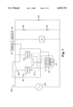
- FIG. 7 is a schematic illustration of the control mechanism for the present suspension system.
- FIG. 8 is an idealized illustration of the motion ratio of the present suspension system.
- FIG. 9 is an idealized illustration of the motion ratio of a suspension system in which the biasing/dampening mechanism is displaced along the vehicle chassis.
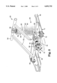
- FIG. 2 is a perspective view of an exemplary suspension system 50 according to the present invention.
- the suspension system 50 of FIG. 2 is configured for use on a snowmobile, it will be understood that the present invention may be utilized on a wide variety of recreational vehicles and that the embodiment of FIG. 2 is for illustration purposes only.
- the suspension system 50 generally includes a pair of suspension arms 52 connected to a vehicle chassis (not shown) at an upper end 54.
- the upper end 54 preferably is pivotally attached either directly to the vehicle chassis or through additional linkage.
- the lower end of the suspension arms 52 are engaged with a slide rail 56 through a slide block linkage mechanism 58.
- slide block linkage mechanisms are further discussed in U.S. Pat. Nos. 5,370,198 (Karpik) and 5,265,692 (Mallette).
- the slide rail 56 is biased away from the upper end 54 of the suspension arms 52 by a biasing/dampening mechanism 60.
- the biasing/dampening mechanism 60 is pivotally mounted at a pivot joint 66 to the upper end 54.
- the lower end of the biasing/dampening mechanism 60 is pivotally mounted at a pivot joint 68 attached to an actuator arm 70.
- the biasing/dampening mechanism in the present embodiment includes a shock absorber 62 and a spring 64, although either component may be used without the other to form the biasing/dampening mechanism. Each component behaves differently to displacement.
- the spring 64 is displacement sensitive. For example, a spring may provide resistance of 100 lbs. for each inch of displacement. By increasing or decreasing the motion ratio of the spring relative to the suspension system, the amount the spring is displaced for a given displacement of the suspension system 50 may be adjusted.
- the shock absorber 62 is primarily speed sensitive. That is, the resistance provided by the shock absorber increases with the speed at which the shock absorber is displaced. In the case of fluid-based shock absorbers, drag of the fluid is proportional to velocity of the fluid squared so that the force versus velocity relationship of the shock absorber is parabolic. Doubling the displacement speed quadruples the resistance of the shock absorber. Shock absorbers tend to be more effective (provide greater resistance) at higher speeds. At a high motion ratio, the shock absorber is displaced over a greater length for a given vertical compression of the suspension system, and hence its operational speed is increased with a corresponding increase in resistance.
- the shock absorber is displaced over a shorter length for the same vertical displacement of the suspension system, and hence its operational speed is decreased with a corresponding decrease in resistance. Therefore, the present suspension system 50 with variable geometry is capable of adjusting both the speed of the shock absorber and the displacement of the spring.
- a motor 72 is located along one side of the slide rail 56.
- the motor 72 is connected to a bevel gear drive 74 by a drive shaft 76.
- the bevel gear drive 74 is operatively connected to a threaded member 78 which engages the mating threaded portion of the actuator arm 70.
- Rotation of the motor 72 causes the actuator arm 70 to move along the axis B.
- the actuator arm 70 and/or housing 90 are preferably beveled at their respective intersection locations to minimize accumulation of ice or debris.
- the motor preferably provides about 7.1 newton-meters to about 10.5 newton-meters of torque at 10 revolutions per minute, when the specified voltage and current are supplied.
- a suitable motor is a Bosch part no. 9000016040 available from Chief Enterprises located in Elmhurst, Ill.
- actuator mechanisms such as hydraulic or pneumatic cylinders
- Various actuators are disclosed in U.S. Pat. Nos. 4,756,517 (Kakimoto), 4,895,383 (Abe et al.), 4,911,466 (Blair), and 5,094,472 (Oyama et al.).
- Movement of the actuator arm 70 along the axis B changes the motion ratio of the suspension system 50.
- the suspension system 50 is in a low motion ratio or soft configuration 80.
- the biasing/dampening mechanism 60 will be at its lowest speed and displacement in the low motion ratio configuration 80.
- the suspension system 50 moves through an intermediate motion ratio configuration 82 to a high motion ratio configuration 84.
- the biasing/dampening mechanism is in its maximum speed and displacement.
- the configuration 84 provides the suspension system 50 with a high motion ratio when subjected to an input force C.
- the configuration 80 provides less resistance to vertical displacement of the suspension system 50 (low motion ratio) to the input force C.
- Moving the lower end of the biasing/dampening mechanism 60 provides a greater change of mechanical advantage to the suspension system 50 than would be realized if the upper end were moved. That is, the greatest change in the motion ratio is effectuated by locating the moving end of the biasing/dampening mechanism on the slide rail, swing arm or other moving member.
- the present actuator arm 70 has a range of motion of about 33 mm (1.3 inches), corresponding to a change of 7.3 cm (2.87 inches) in the vertical travel of the slide rail 56.
- the bevel gear drive 74 preferably includes an indicator, such as a magnet 86, that is detectable by a detector 88 mounted to a housing 90 containing the bevel gear drive 74 and threaded member 78.
- Control electronics 92 (see FIG. 7) is preferably a programmable logic controller for monitoring the detector 88 and counting the rotations of the bevel gear drive 74 so that the position of the actuator arm 70 can be displayed to the driver via a display 94 to the rider.
- a simple switch may be used in place of the control electronics 92.
- a linear variable displacement transducer or a variety of other device may be used to sense the position of the actuator arm 70.
- control electronics 92 In the event the control electronics 92 does not receive a pulse from the detector 88 for some period of time during which the motor 72 has been activated, the control electronics 92 assumes that the actuator arm 70 has reached a limit to its physical range of motion and subsequently terminates the power to the motor 72. Similarly, if movement of the actuator arm 70 is blocked by ice or another obstruction, the control electronics 92 will sense the lack of movement and signal an error to the rider via the display device 94 and terminate the power to the motor 72. Non-volatile memory is provided to store the last position until the vehicle is started again.
- FIG. 3 is a schematic illustration of an alternate snowmobile suspension system 50' according to the present invention.
- Suspension arm 52' pivotally connects slide rail 56' to a rocker arm 100.
- the top edge of the rocker arm 100 is pivotally connected to a biasing/dampening mechanism 60'.
- the biasing/dampening mechanism 60' may be a shock absorber 62' and/or a spring 64'.
- the other end of the biasing/dampening mechanism 60' is pivotally mounted to the chassis (not shown) through another rocker arm of the snowmobile.
- the lower end of the rocker arm 100 is pivotally mounted to a pull rod 102.
- the other end of the pull rod 102 is pivotally engaged with the actuator arm 70' on the actuator 72', such as the motor described in FIG. 2.
- the actuator arm 70' moves along an axis B so as to displace the pull rod 102'. Extending the actuator arm 70' causes the pull rod 102' to rotate the rocker arm 100 in a counterclockwise direction. Retraction of the actuator arm 70' rotates the rocker arm 100 in a clockwise direction. This rotational variation increases or decrease the speed and displacement of the biasing/dampening mechanism 60'. Increasing the speed and displacement of the biasing/dampening mechanism 60' corresponds to a higher motion ratio configuration and a stiffening of the suspension system 50'. Similarly, retraction of the actuator arm 70' causes the rocker arm 100 to rotate in a clockwise direction and the speed and displacement of the biasing/dampening mechanism 60' to be increased. Decreasing the speed and displacement of the biasing/dampening mechanism 60' corresponds to a lower motion ratio and a softer ride on the vehicle.
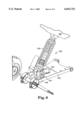
- FIG. 4 is a schematic illustration of an alternate snowmobile suspension system 50" according to the present invention.
- a biasing/dampening mechanism 60" is attached either directly or via a linkage system to a slide rail 56" at one end and an actuator arm 70" at the other end.
- the actuator 72" is preferably rigidly attached to the suspension arm 74".
- the actuator arm extends and retracts along an axis B" in response to the control electronics 92.
- the actuator arm 70" is moved to the retracted position toward the actuator 72"
- the speed and displacement of the biasing/dampening mechanism 60" is reduced, resulting in a lower motion ratio.
- the speed and displacement of the biasing/dampening mechanism 60" is increased, corresponding to a higher motion ratio.
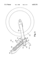
- FIG. 5 is a schematic illustration of a suspension system 150 according to the present invention for use on a motorcycle or bicycle.
- the rear wheel 152 of the motorcycle is pivotally mounted to the frame 154 by frame member or swing arm 156.
- the frame member 156 is attached to the frame 150 at pivoting joint 158.
- the frame member 156 is biased downward by a biasing/dampening mechanism 160 which is pivotally attached to an upper portion of the frame at a location 162.
- the lower portion of the biasing/dampening mechanism 160 is pivotally attached to an actuator arm 164 that can be displaced along an axis 166 by an actuator 168.
- the actuator 168 is pivotally mounted to the frame member 156 at a location 170.
- the position of the actuator 168 relative to the frame 154 is maintained by linkage 172. Locating the actuator 168 on the swing arm 156 provides a greater variation in the mechanical advantage and greater change in the motion ratio than locating it proximate the location 162.
- the actuator arm 164 is retracted, the speed and displacement of the biasing/dampening mechanism 160 is reduced, resulting in a lower motion ratio and a softer ride.
- the actuator arm 164 is extended, the speed and displacement of the biasing/dampening mechanism 160 is increased, resulting in a higher motion ratio and a stiffer ride.
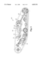
- FIG. 6 is a perspective view of an exemplary suspension system 180 suitable for use in an all terrain vehicle (not shown).
- a swing arm or suspension member 182 is biased downwards away from the vehicle chassis 186 by a biasing/dampening mechanism 184.
- the biasing/dampening mechanism 184 is pivotally mounted to the chassis 186 at one end and to an actuator arm 188 on an actuator 192 at the other end.
- the actuator 192 is preferably rigidly mounted to the swing arm 182.
- the actuator arm 188 may be displaced along an axis 190 so as to change the speed and displacement of the biasing/dampening mechanism 184. Locating the actuator 192 on the swing arm 182 provides a greater change in the mechanical advantage and a greater change in the motion ratio than locating it proximate the location 186.
- the present suspension system requires considerable power to alter the motion ratio during operation of the vehicle. While it would be possible to design an electric power source or other power source on a recreational vehicle with adequate capacity to operate the present suspension system or other components requiring considerable power such as a fuel injection system without a battery, retrofitting the present suspension system to an existing vehicle has proven somewhat problematic.
- snowmobiles typically utilize a magneto for generating electric power for the lights, heaters, and ignition system. The magneto generates between about 20 volts AC during idling to 80 volts AC at high RPMs at about 3-10 amps.
- FIG. 7 is a schematic illustration of one approach to maximizing the power output from the magneto on an existing recreational vehicle. Rather than powering the motor 72 of the present vehicle suspension system 50 in parallel with the heaters 202 and lights 204 of the vehicle, motor 72 is arranged in series upstream of the electrical components on the vehicle to receive raw power directly from the magneto 206 before power is provided to the other electrical components on the vehicle.
- the controller 92 activates a toggle switch 208 to divert alternating current directly from the recreational vehicle's magneto/electric generator 206.
- the alternating current is converted to DC current in an A-to-D converter 210.
- the direct current is routed through a directional relay 213 in parallel with a voltage regulator 211 to the motor 72 to operate the motor at about 18 V DC .
- the relay 213 switches the motor 72 in and out with the standard electrical system on the vehicle.
- a capacitor in the range of about 1500 ⁇ F is provided in the motor to reduce voltage fluctuations.
- the remaining current is then converted back to AC by a D-to-A converter 212 and directed to supply the rest of the vehicle's electrical requirements.
- the motor 72 drives the actuator arm in the chosen direction to vary the motion ratio of the suspension system.
- the controller 92 continues to direct power to the motor 72 until the detector 88 indicates the desired motion ratio has been attained or the actuator arm 70 has stopped moving for some period of time.
- the controller 92 deactivates the motor 72, power from the magneto 206 is redirected to the recreational vehicle's normal electrical system by switch 208.
- FIGS. 8 and 9 show idealized suspension systems to schematically illustrate the advantage of locating the actuator on the moving frame member or swing arm, rather than on the fixed frame or chassis of the vehicle.
- the swing arms had a length of 201.5 mm.
- the swing arm 250 is permitted to pivot about location 252 through an arc of 45°; 22.5° above and below horizontal, corresponding to a suspension travel distance of 154.2 mm.
- the active end of the biasing/dampening mechanism 254 was displaced 33 mm from vertical.
- the active end of the biasing/dampening mechanism is at location zero when in the vertical configuration and at 33 mm when fully displaced.
- Motion ratio was defined as the displacement of the biasing/dampening mechanism/total displacement of the suspension system.
- FIG. 8 is a schematic illustration of an exemplary motion ratio for a suspension system according to the present invention.
- the displacement of the biasing/dampening mechanism takes place along segment 256 of the moving portion of the suspension system, in this case, along the swing arm 250.
- the compressed length 254A of the biasing/dampening mechanism is about 139.26 mm and the extended length 254B of the biasing/dampening mechanism is about 240.38 mm.
- the compressed length 254C of the biasing/dampening mechanism is about 130.25 mm and the extended length 254D of the biasing/dampening mechanism is about 254.84 mm.
- the percentage change of the motion ratio as a result of 33 mm of displacement along the swing arm 250 was about 23%.
- FIG. 9 is a schematic illustration of a suspension system in which the biasing/dampening mechanism 260 is displaced along segment 262 on the chassis or frame of the vehicle, rather than on the swing arm 250.
- the compressed length 260A of the biasing/dampening mechanism is about 128.46 mm and the extended length 260B is about 254.84 mm.
- the compressed length 260C of the biasing/dampening mechanism is about 132.63 mm and the extended length 254D is about 256.97 mm.
- the percentage change of the motion ratio as a result of 33 mm of displacement along the chassis was about 1.3%. Therefore, in spite of the risk of environmental contamination or damage, there is a significant advantage in locating the mechanism for displacing the biasing/dampening mechanism along the moving portion of the suspension system, such as on the swing arm.
Landscapes
- Engineering & Computer Science (AREA)
- Mechanical Engineering (AREA)
- Vehicle Body Suspensions (AREA)
- Axle Suspensions And Sidecars For Cycles (AREA)
Abstract
Description
Claims (29)
Priority Applications (2)
Application Number | Priority Date | Filing Date | Title |
---|---|---|---|
US08/853,442 US6032752A (en) | 1997-05-09 | 1997-05-09 | Vehicle suspension system with variable geometry |
US09/483,968 US6237706B1 (en) | 1997-05-09 | 2000-01-18 | Vehicle suspension system with variable geometry |
Applications Claiming Priority (1)
Application Number | Priority Date | Filing Date | Title |
---|---|---|---|
US08/853,442 US6032752A (en) | 1997-05-09 | 1997-05-09 | Vehicle suspension system with variable geometry |
Related Child Applications (1)
Application Number | Title | Priority Date | Filing Date |
---|---|---|---|
US09/483,968 Continuation US6237706B1 (en) | 1997-05-09 | 2000-01-18 | Vehicle suspension system with variable geometry |
Publications (1)
Publication Number | Publication Date |
---|---|
US6032752A true US6032752A (en) | 2000-03-07 |
Family
ID=25316046
Family Applications (2)
Application Number | Title | Priority Date | Filing Date |
---|---|---|---|
US08/853,442 Expired - Fee Related US6032752A (en) | 1997-05-09 | 1997-05-09 | Vehicle suspension system with variable geometry |
US09/483,968 Expired - Fee Related US6237706B1 (en) | 1997-05-09 | 2000-01-18 | Vehicle suspension system with variable geometry |
Family Applications After (1)
Application Number | Title | Priority Date | Filing Date |
---|---|---|---|
US09/483,968 Expired - Fee Related US6237706B1 (en) | 1997-05-09 | 2000-01-18 | Vehicle suspension system with variable geometry |
Country Status (1)
Country | Link |
---|---|
US (2) | US6032752A (en) |
Cited By (43)
Publication number | Priority date | Publication date | Assignee | Title |
---|---|---|---|---|
US6112840A (en) * | 1998-02-25 | 2000-09-05 | Forbes; Vernal D. | Snow vehicle |
US6237706B1 (en) * | 1997-05-09 | 2001-05-29 | Fast Action Support Team, Inc. | Vehicle suspension system with variable geometry |
US6321864B1 (en) | 2000-04-27 | 2001-11-27 | Vernal D. Forbes | Snow vehicle track suspension |
US6390219B1 (en) * | 2000-09-21 | 2002-05-21 | Bombardier Inc. | Rear suspension system for a snowmobile |
US6401852B2 (en) * | 1998-04-24 | 2002-06-11 | Lillbacka Jetair Oy | Snowmobile suspension system |
US6431301B1 (en) | 1998-02-25 | 2002-08-13 | Vernal D. Forbes | Snow vehicle conversion kit |
US6499551B2 (en) | 1998-12-31 | 2002-12-31 | Formula Fast Racing | Snowmobile construction |
US6691649B2 (en) | 2000-07-19 | 2004-02-17 | Bombardier-Rotax Gmbh | Fuel injection system for a two-stroke engine |
US6715575B2 (en) | 2001-08-16 | 2004-04-06 | Formula Fast Racing | Track tensioning system for a tracked vehicle |
US20050077693A1 (en) * | 2003-10-08 | 2005-04-14 | Simmons Verlin M. | Wear bar for snow machine ski |
US6880660B1 (en) | 2001-09-07 | 2005-04-19 | Polaris Industries Inc. | Snowmobile |
US6899191B1 (en) | 2004-01-30 | 2005-05-31 | Sno-Bear Industries, Llc | Actuated ski suspension |
US6926108B1 (en) | 2002-09-03 | 2005-08-09 | Great Lakes Sound & Vibration, Inc. | Snowmobile rear suspension system |
US6971466B1 (en) * | 2004-01-30 | 2005-12-06 | Sno-Bear Industries, Llc | Torque compensating rear undercarriage for track driven vehicles |
US20060064223A1 (en) * | 2004-09-20 | 2006-03-23 | Darrell Voss | Vehicle systems and method |
US7040426B1 (en) | 2002-06-04 | 2006-05-09 | Polaris Industries, Inc. | Suspension for a tracked vehicle |
US7059440B1 (en) | 2001-09-07 | 2006-06-13 | Polaris Industries Inc. | Snowmobile |
US20060180370A1 (en) * | 2002-09-03 | 2006-08-17 | Polakowski Stephen E | Snowmobile rear suspension system |
US7185902B1 (en) | 2003-03-14 | 2007-03-06 | Altair Engineering, Inc. | Strut suspension with pivoting rocker arm |
US20070227796A1 (en) * | 2005-09-28 | 2007-10-04 | Simmons Val J | Suspension for tracked vehicles |
US20090321167A1 (en) * | 2005-09-28 | 2009-12-31 | Simmons Val J | Suspension for tracked vehicles |
US7673711B1 (en) | 2002-06-04 | 2010-03-09 | Polaris Industries Inc. | Tracked vehicle |
US20120111843A1 (en) * | 2010-11-08 | 2012-05-10 | James Beard | Mobile, climbing robotic system to perform remote welds on ferrous materials |
US8333256B2 (en) | 2009-08-13 | 2012-12-18 | Rustam Stolkin | Polymorphic tracked vehicle |
CN103182914A (en) * | 2012-01-02 | 2013-07-03 | 福特全球技术公司 | Wheel suspension for vehicle |
US8676440B2 (en) | 2010-12-22 | 2014-03-18 | Magna International Inc. | Semi-active snowmobile rear suspension |
WO2014074711A1 (en) * | 2012-11-07 | 2014-05-15 | Polaris Industries Inc. | Vehicle having suspension with continuous damping control |
US9145037B2 (en) | 2013-05-31 | 2015-09-29 | Skinz Protective Gear | Remotely adjustable suspension coupling |
US9205717B2 (en) | 2012-11-07 | 2015-12-08 | Polaris Industries Inc. | Vehicle having suspension with continuous damping control |
US9346518B2 (en) | 2013-07-30 | 2016-05-24 | Great Lakes Sound & Vibration, Inc. | Snowmobile suspension systems |
DE102014017979A1 (en) | 2014-12-04 | 2016-06-09 | Audi Ag | Vibration damper for a motor vehicle |
US9428028B2 (en) | 2013-05-31 | 2016-08-30 | Skinz Protective Gear | Remotely adjustable degrees of freedom for suspension coupling |
US20170057573A1 (en) * | 2015-08-25 | 2017-03-02 | Randy J. Gentry | Snowmobile suspension system |
US10005506B2 (en) | 2015-02-27 | 2018-06-26 | Great Lakes Sound & Vibration, Inc. | Suspension arrangements for vehicles |
US10124709B2 (en) | 2015-05-15 | 2018-11-13 | Polaris Industries Inc. | Utility vehicle |
US10384504B2 (en) | 2015-12-16 | 2019-08-20 | SnoBear USA, Inc. | Transport trailer |
US10406884B2 (en) | 2017-06-09 | 2019-09-10 | Polaris Industries Inc. | Adjustable vehicle suspension system |
US10843520B2 (en) * | 2018-05-04 | 2020-11-24 | Hendrickson Usa, L.L.C. | Heavy-duty vehicle axle/suspension system with optimized damping |
US10946736B2 (en) | 2018-06-05 | 2021-03-16 | Polaris Industries Inc. | All-terrain vehicle |
US10987987B2 (en) | 2018-11-21 | 2021-04-27 | Polaris Industries Inc. | Vehicle having adjustable compression and rebound damping |
US11110913B2 (en) | 2016-11-18 | 2021-09-07 | Polaris Industries Inc. | Vehicle having adjustable suspension |
US11904648B2 (en) | 2020-07-17 | 2024-02-20 | Polaris Industries Inc. | Adjustable suspensions and vehicle operation for off-road recreational vehicles |
US11919524B2 (en) | 2014-10-31 | 2024-03-05 | Polaris Industries Inc. | System and method for controlling a vehicle |
Families Citing this family (18)
Publication number | Priority date | Publication date | Assignee | Title |
---|---|---|---|---|
US6631778B2 (en) * | 2000-02-09 | 2003-10-14 | Bombardier Inc. | Shock linkage assembly for a snowmobile suspension system |
WO2003019309A1 (en) * | 2001-08-23 | 2003-03-06 | General Motors Corporation | Vehicle chassis having programmable operating characteristics and method for using same |
US6968918B2 (en) | 2001-08-23 | 2005-11-29 | General Motors Corporation | Vehicle chassis having programmable operating characteristics and method for using same |
US20030037982A1 (en) * | 2001-08-23 | 2003-02-27 | Chernoff Adrian B. | Vehicle chassis having programmable operating characteristics and method for using same |
JP2004149002A (en) * | 2002-10-31 | 2004-05-27 | Yamaha Motor Co Ltd | Rear suspension for snowmobile |
US7048292B2 (en) * | 2003-09-25 | 2006-05-23 | David Weagle | Bicycle suspension systems |
US7051828B2 (en) * | 2004-01-28 | 2006-05-30 | David Murrin | Wheel mechanism for ski-equipped vehicles |
US7625000B2 (en) * | 2004-12-06 | 2009-12-01 | Zarach Industries, Inc. | Variable ratio floating suspension system |
US20090008990A1 (en) * | 2005-03-01 | 2009-01-08 | Guy Sibilleau | Rail slides for track suspension systems |
US7455141B2 (en) * | 2005-03-25 | 2008-11-25 | Hildebrand William B E | Track drive system |
US7661503B2 (en) * | 2005-04-07 | 2010-02-16 | Orion Dynamics, Inc. | Vehicle suspension system for stable squat magnitude responses |
US7643979B2 (en) * | 2006-01-17 | 2010-01-05 | Rambus Inc. | Method to analyze an analog circuit design with a verification program |
US7421361B2 (en) * | 2006-03-27 | 2008-09-02 | Dell Products L.P. | Automated factory install printer test process |
US7717212B2 (en) * | 2006-08-25 | 2010-05-18 | Split Pivot, Inc. | Vehicle suspension systems for seperated acceleration responses |
US7703785B2 (en) * | 2007-08-16 | 2010-04-27 | Trek Bicycle Corporation | Bicycle derailleur system |
US7837213B2 (en) | 2007-04-16 | 2010-11-23 | Trek Bicycle Corporation | Bicycle rear wheel suspension system |
WO2010033174A1 (en) * | 2008-09-16 | 2010-03-25 | Evil Bikes Llc | Improved bicycle suspension systems |
US8413747B2 (en) * | 2010-11-08 | 2013-04-09 | James Walter Beard | Suspension for an endless track climbing machine |
Citations (49)
Publication number | Priority date | Publication date | Assignee | Title |
---|---|---|---|---|
FR1035475A (en) * | 1951-04-17 | 1953-08-25 | Removable lifting tracks for trucks and tractors | |
US3115945A (en) * | 1960-11-21 | 1963-12-31 | Claud J Dry | Chassis support apparatus and system |
US3527505A (en) * | 1969-01-24 | 1970-09-08 | Textron Inc | Snowmobile track suspension system |
US3637265A (en) * | 1970-02-02 | 1972-01-25 | Louis A Valentine | Track slide assembly for snowmobiles |
CA895747A (en) * | 1972-03-21 | D. Reese Gerald | Suspension system for tracked vehicle | |
US3658392A (en) * | 1969-01-10 | 1972-04-25 | Bombardier Ltd | Tracked vehicle suspension |
US3711164A (en) * | 1971-03-09 | 1973-01-16 | Poly Traction Inc | Snowmobile slide rail suspension |
US3721308A (en) * | 1971-02-04 | 1973-03-20 | Textron Inc | Snowmobile suspension system |
US3727709A (en) * | 1971-09-27 | 1973-04-17 | Rupp Industries | Snowmobile construction |
US3744583A (en) * | 1971-09-13 | 1973-07-10 | E Bedard | Snow vehicle and suspension system therefor |
US3788412A (en) * | 1972-05-17 | 1974-01-29 | Coleman Co | Snowmobile suspension system |
CA944001A (en) * | 1971-09-19 | 1974-03-19 | Dayco Corporation | Snowmobile slide rail suspension |
US3879092A (en) * | 1973-12-19 | 1975-04-22 | Outboard Marine Corp | Snowmobile track suspension system |
US3913693A (en) * | 1971-03-22 | 1975-10-21 | Outboard Marine Corp | Snowmobile drive suspension system |
US3913694A (en) * | 1974-04-01 | 1975-10-21 | Brunswick Corp | Suspension apparatus for ground engaging drive tracks |
US3933213A (en) * | 1974-04-11 | 1976-01-20 | Brunswick Corporation | Variable response snowmobile suspension system |
US3944005A (en) * | 1973-12-28 | 1976-03-16 | Yamaha Hatsudoki Kabushiki Kaisha | Suspension device for vehicles |
US3945663A (en) * | 1973-07-27 | 1976-03-23 | Jonas Woodhead Limited | Oleo/pneumatic levelling struts |
US3966181A (en) * | 1974-03-11 | 1976-06-29 | Bombardier Limited | Suspension spring adjuster |
US3966151A (en) * | 1974-01-18 | 1976-06-29 | Hawkins Iii Carl V | Bottom fishing device |
CA994395A (en) * | 1972-11-15 | 1976-08-03 | Marcel Vincent | Snowmobile suspension system |
US4057916A (en) * | 1975-11-17 | 1977-11-15 | Roemer Benjamin C | Snowmobile trail leveler |
US4131266A (en) * | 1977-10-19 | 1978-12-26 | Jackson Machine Products | Adjustable shock absorber |
US4222453A (en) * | 1978-11-17 | 1980-09-16 | Arctic Enterprises, Inc. | Rear suspension system for a snowmobile |
US4226408A (en) * | 1978-02-01 | 1980-10-07 | Honda Giken Kogyo Kabushiki Kaisha | Hydraulic shock absorber for vehicles |
US4311302A (en) * | 1978-12-22 | 1982-01-19 | Fichtel & Sachs Ag | Shock absorber device |
US4407386A (en) * | 1981-12-31 | 1983-10-04 | Yamaha Hatsudoki Kabushiki Kaisha | Snowmobile suspension unit |
US4411342A (en) * | 1979-02-23 | 1983-10-25 | Tokico Ltd. | Hydraulic damper |
US4442926A (en) * | 1980-06-06 | 1984-04-17 | Tokiko Kabushiki Kaisha | Simplified hydraulic damper |
US4518056A (en) * | 1981-08-11 | 1985-05-21 | Yamaha Hatsudoki Kabushiki Kaisha | Snowmobile |
FI850110L (en) * | 1985-01-10 | 1986-07-11 | Jorma Samuli Kuusinen | LAETT SNOEFORDON. |
US4700815A (en) * | 1984-01-20 | 1987-10-20 | Quinton Hazell Plc | Vehicle suspension system |
US4756517A (en) * | 1984-09-05 | 1988-07-12 | Nissan Motor Company, Limited | Strut suspension structure of automobile vehicle with variable geometry |
US4843293A (en) * | 1987-02-02 | 1989-06-27 | Research Development Corporation | Apparatus for controlling servo system employing piezo-electric actuator |
US4895383A (en) * | 1987-04-21 | 1990-01-23 | Honda Giken Kogyo Kabushiki Kaisha | Method of and apparatus for controlling camber of rear wheels of four-wheel-steerable vehicle |
US4911466A (en) * | 1989-05-25 | 1990-03-27 | Alfred Blair | Constant camber suspension |
US4987965A (en) * | 1990-01-17 | 1991-01-29 | Bombardier Inc. | Snowmobile suspension |
FI901451A (en) * | 1990-03-23 | 1991-09-24 | Eero Juhani Upola | APPARATUR FOER REGLERING AV BAND I EN MOTORKAELKE UNDER KOERNING. |
US5086861A (en) * | 1990-04-06 | 1992-02-11 | Peterson Donald W | Electric rear wheel steering actuator |
US5094472A (en) * | 1986-05-16 | 1992-03-10 | Honda Giken Kogyo Kabushiki Kaisha | Camber control system for motor vehicle |
US5172786A (en) * | 1990-03-02 | 1992-12-22 | Yamaha Hatsudoki Kabushiki Kaisha | V belt type automatic transmission system |
US5199401A (en) * | 1991-10-21 | 1993-04-06 | Eaton Corporation | Engine throttle servoactuator control system |
US5265692A (en) * | 1991-12-11 | 1993-11-30 | Bombardier Inc. | Snowmobile suspension |
US5270625A (en) * | 1991-09-25 | 1993-12-14 | Systems, Machines, Automation Components | Pneumatic/electric actuator |
US5333989A (en) * | 1992-12-23 | 1994-08-02 | General Electric Company | Electric actuators for steam turbine valves |
US5353902A (en) * | 1992-06-16 | 1994-10-11 | Dana Corporation | Electric actuator assembly for clutch |
US5370198A (en) * | 1992-09-25 | 1994-12-06 | Karpik; Gerard J. | Long travel suspension for tracked vehicle |
US5450202A (en) * | 1988-11-17 | 1995-09-12 | Tisue; James G. | Adaptive resonant positioner having random access capability |
US5667031A (en) * | 1992-09-25 | 1997-09-16 | Polaris Industries Partners L.P. | Long travel suspension for tracked vehicle |
Family Cites Families (1)
Publication number | Priority date | Publication date | Assignee | Title |
---|---|---|---|---|
US6032752A (en) * | 1997-05-09 | 2000-03-07 | Fast Action Support Team, Inc. | Vehicle suspension system with variable geometry |
-
1997
- 1997-05-09 US US08/853,442 patent/US6032752A/en not_active Expired - Fee Related
-
2000
- 2000-01-18 US US09/483,968 patent/US6237706B1/en not_active Expired - Fee Related
Patent Citations (53)
Publication number | Priority date | Publication date | Assignee | Title |
---|---|---|---|---|
CA895747A (en) * | 1972-03-21 | D. Reese Gerald | Suspension system for tracked vehicle | |
FR1035475A (en) * | 1951-04-17 | 1953-08-25 | Removable lifting tracks for trucks and tractors | |
US3115945A (en) * | 1960-11-21 | 1963-12-31 | Claud J Dry | Chassis support apparatus and system |
US3658392A (en) * | 1969-01-10 | 1972-04-25 | Bombardier Ltd | Tracked vehicle suspension |
US3527505A (en) * | 1969-01-24 | 1970-09-08 | Textron Inc | Snowmobile track suspension system |
US3637265A (en) * | 1970-02-02 | 1972-01-25 | Louis A Valentine | Track slide assembly for snowmobiles |
US3721308A (en) * | 1971-02-04 | 1973-03-20 | Textron Inc | Snowmobile suspension system |
US3711164A (en) * | 1971-03-09 | 1973-01-16 | Poly Traction Inc | Snowmobile slide rail suspension |
US3913693A (en) * | 1971-03-22 | 1975-10-21 | Outboard Marine Corp | Snowmobile drive suspension system |
US3744583A (en) * | 1971-09-13 | 1973-07-10 | E Bedard | Snow vehicle and suspension system therefor |
CA944001A (en) * | 1971-09-19 | 1974-03-19 | Dayco Corporation | Snowmobile slide rail suspension |
CA956674A (en) * | 1971-09-27 | 1974-10-22 | Neil A. Newman | Snowmobile construction |
US3727709A (en) * | 1971-09-27 | 1973-04-17 | Rupp Industries | Snowmobile construction |
US3788412A (en) * | 1972-05-17 | 1974-01-29 | Coleman Co | Snowmobile suspension system |
CA994395A (en) * | 1972-11-15 | 1976-08-03 | Marcel Vincent | Snowmobile suspension system |
US3945663A (en) * | 1973-07-27 | 1976-03-23 | Jonas Woodhead Limited | Oleo/pneumatic levelling struts |
US3879092A (en) * | 1973-12-19 | 1975-04-22 | Outboard Marine Corp | Snowmobile track suspension system |
CA1029425A (en) * | 1973-12-19 | 1978-04-11 | Edgar Rose | Snowmobile track suspension system |
US3944005A (en) * | 1973-12-28 | 1976-03-16 | Yamaha Hatsudoki Kabushiki Kaisha | Suspension device for vehicles |
US3966151A (en) * | 1974-01-18 | 1976-06-29 | Hawkins Iii Carl V | Bottom fishing device |
US3966181A (en) * | 1974-03-11 | 1976-06-29 | Bombardier Limited | Suspension spring adjuster |
US3913694A (en) * | 1974-04-01 | 1975-10-21 | Brunswick Corp | Suspension apparatus for ground engaging drive tracks |
CA1026807A (en) * | 1974-04-01 | 1978-02-21 | Brunswick Corporation | Suspension apparatus for ground engaging drive tracks |
US3933213A (en) * | 1974-04-11 | 1976-01-20 | Brunswick Corporation | Variable response snowmobile suspension system |
US4057916A (en) * | 1975-11-17 | 1977-11-15 | Roemer Benjamin C | Snowmobile trail leveler |
US4131266A (en) * | 1977-10-19 | 1978-12-26 | Jackson Machine Products | Adjustable shock absorber |
US4226408A (en) * | 1978-02-01 | 1980-10-07 | Honda Giken Kogyo Kabushiki Kaisha | Hydraulic shock absorber for vehicles |
US4222453A (en) * | 1978-11-17 | 1980-09-16 | Arctic Enterprises, Inc. | Rear suspension system for a snowmobile |
US4311302A (en) * | 1978-12-22 | 1982-01-19 | Fichtel & Sachs Ag | Shock absorber device |
US4411342A (en) * | 1979-02-23 | 1983-10-25 | Tokico Ltd. | Hydraulic damper |
US4442926A (en) * | 1980-06-06 | 1984-04-17 | Tokiko Kabushiki Kaisha | Simplified hydraulic damper |
US4518056A (en) * | 1981-08-11 | 1985-05-21 | Yamaha Hatsudoki Kabushiki Kaisha | Snowmobile |
US4407386A (en) * | 1981-12-31 | 1983-10-04 | Yamaha Hatsudoki Kabushiki Kaisha | Snowmobile suspension unit |
US4700815A (en) * | 1984-01-20 | 1987-10-20 | Quinton Hazell Plc | Vehicle suspension system |
US4756517A (en) * | 1984-09-05 | 1988-07-12 | Nissan Motor Company, Limited | Strut suspension structure of automobile vehicle with variable geometry |
FI850110L (en) * | 1985-01-10 | 1986-07-11 | Jorma Samuli Kuusinen | LAETT SNOEFORDON. |
US5094472A (en) * | 1986-05-16 | 1992-03-10 | Honda Giken Kogyo Kabushiki Kaisha | Camber control system for motor vehicle |
US4843293A (en) * | 1987-02-02 | 1989-06-27 | Research Development Corporation | Apparatus for controlling servo system employing piezo-electric actuator |
US4895383A (en) * | 1987-04-21 | 1990-01-23 | Honda Giken Kogyo Kabushiki Kaisha | Method of and apparatus for controlling camber of rear wheels of four-wheel-steerable vehicle |
US5450202A (en) * | 1988-11-17 | 1995-09-12 | Tisue; James G. | Adaptive resonant positioner having random access capability |
US4911466A (en) * | 1989-05-25 | 1990-03-27 | Alfred Blair | Constant camber suspension |
US4987965A (en) * | 1990-01-17 | 1991-01-29 | Bombardier Inc. | Snowmobile suspension |
US5172786A (en) * | 1990-03-02 | 1992-12-22 | Yamaha Hatsudoki Kabushiki Kaisha | V belt type automatic transmission system |
FI901451A (en) * | 1990-03-23 | 1991-09-24 | Eero Juhani Upola | APPARATUR FOER REGLERING AV BAND I EN MOTORKAELKE UNDER KOERNING. |
US5086861A (en) * | 1990-04-06 | 1992-02-11 | Peterson Donald W | Electric rear wheel steering actuator |
US5270625A (en) * | 1991-09-25 | 1993-12-14 | Systems, Machines, Automation Components | Pneumatic/electric actuator |
US5199401A (en) * | 1991-10-21 | 1993-04-06 | Eaton Corporation | Engine throttle servoactuator control system |
US5265692A (en) * | 1991-12-11 | 1993-11-30 | Bombardier Inc. | Snowmobile suspension |
US5353902A (en) * | 1992-06-16 | 1994-10-11 | Dana Corporation | Electric actuator assembly for clutch |
US5370198A (en) * | 1992-09-25 | 1994-12-06 | Karpik; Gerard J. | Long travel suspension for tracked vehicle |
US5667031A (en) * | 1992-09-25 | 1997-09-16 | Polaris Industries Partners L.P. | Long travel suspension for tracked vehicle |
US5881834A (en) * | 1992-09-25 | 1999-03-16 | Polaris Industries Partners L.P. | Long travel suspension for tracked vehicle |
US5333989A (en) * | 1992-12-23 | 1994-08-02 | General Electric Company | Electric actuators for steam turbine valves |
Cited By (75)
Publication number | Priority date | Publication date | Assignee | Title |
---|---|---|---|---|
US6237706B1 (en) * | 1997-05-09 | 2001-05-29 | Fast Action Support Team, Inc. | Vehicle suspension system with variable geometry |
US6431301B1 (en) | 1998-02-25 | 2002-08-13 | Vernal D. Forbes | Snow vehicle conversion kit |
US6302232B1 (en) | 1998-02-25 | 2001-10-16 | Vernal D. Forbes | Snow vehicle |
US6112840A (en) * | 1998-02-25 | 2000-09-05 | Forbes; Vernal D. | Snow vehicle |
US6382338B1 (en) | 1998-02-25 | 2002-05-07 | Vernal D. Forbes | Snow vehicle |
US6626258B1 (en) | 1998-02-25 | 2003-09-30 | Vernal D. Forbes | Snow vehicle |
US6401852B2 (en) * | 1998-04-24 | 2002-06-11 | Lillbacka Jetair Oy | Snowmobile suspension system |
US6561302B2 (en) | 1998-12-31 | 2003-05-13 | Formula Fast Racing | Snowmobile construction |
US6499551B2 (en) | 1998-12-31 | 2002-12-31 | Formula Fast Racing | Snowmobile construction |
US20040134702A1 (en) * | 1998-12-31 | 2004-07-15 | Formula Fast Racing | Snowmobile construction |
US6889787B2 (en) | 1998-12-31 | 2005-05-10 | Gerard J. Karpik | Snowmobile construction |
US6691812B2 (en) | 1998-12-31 | 2004-02-17 | Formula Fast Racing | Snowmobile construction |
US6321864B1 (en) | 2000-04-27 | 2001-11-27 | Vernal D. Forbes | Snow vehicle track suspension |
US6691649B2 (en) | 2000-07-19 | 2004-02-17 | Bombardier-Rotax Gmbh | Fuel injection system for a two-stroke engine |
US6390219B1 (en) * | 2000-09-21 | 2002-05-21 | Bombardier Inc. | Rear suspension system for a snowmobile |
US20040173390A1 (en) * | 2001-08-16 | 2004-09-09 | Formula Fast Racing | Track tensioning system for a tracked vehicle |
US6715575B2 (en) | 2001-08-16 | 2004-04-06 | Formula Fast Racing | Track tensioning system for a tracked vehicle |
US6880660B1 (en) | 2001-09-07 | 2005-04-19 | Polaris Industries Inc. | Snowmobile |
US7059440B1 (en) | 2001-09-07 | 2006-06-13 | Polaris Industries Inc. | Snowmobile |
US7040426B1 (en) | 2002-06-04 | 2006-05-09 | Polaris Industries, Inc. | Suspension for a tracked vehicle |
US7673711B1 (en) | 2002-06-04 | 2010-03-09 | Polaris Industries Inc. | Tracked vehicle |
US8167073B2 (en) | 2002-09-03 | 2012-05-01 | Great Lakes Sound & Vibration, Inc. | Snowmobile rear suspension system |
US7594557B2 (en) | 2002-09-03 | 2009-09-29 | Great Lakes Sound & Vibration, Inc. | Snowmobile rear suspension system |
US20090294197A1 (en) * | 2002-09-03 | 2009-12-03 | Great Lakes Sound & Vibration, Inc. | Snowmobile Rear Suspension System |
US20050183899A1 (en) * | 2002-09-03 | 2005-08-25 | Great Lakes Sound & Vibration, Inc. | Snowmobile rear suspension system |
US6926108B1 (en) | 2002-09-03 | 2005-08-09 | Great Lakes Sound & Vibration, Inc. | Snowmobile rear suspension system |
US20060180370A1 (en) * | 2002-09-03 | 2006-08-17 | Polakowski Stephen E | Snowmobile rear suspension system |
US7128180B2 (en) | 2002-09-03 | 2006-10-31 | Great Lakes Sound & Vibration, Inc. | Snowmobile rear suspension system |
US7185902B1 (en) | 2003-03-14 | 2007-03-06 | Altair Engineering, Inc. | Strut suspension with pivoting rocker arm |
US7275751B2 (en) | 2003-10-08 | 2007-10-02 | Simmons Verlin M | Wear bar for snow machine ski |
US20050077693A1 (en) * | 2003-10-08 | 2005-04-14 | Simmons Verlin M. | Wear bar for snow machine ski |
US6899191B1 (en) | 2004-01-30 | 2005-05-31 | Sno-Bear Industries, Llc | Actuated ski suspension |
US6971466B1 (en) * | 2004-01-30 | 2005-12-06 | Sno-Bear Industries, Llc | Torque compensating rear undercarriage for track driven vehicles |
US20060064223A1 (en) * | 2004-09-20 | 2006-03-23 | Darrell Voss | Vehicle systems and method |
US7533750B2 (en) | 2005-09-28 | 2009-05-19 | Simmons, Inc. | Suspension for tracked vehicles |
US20090321167A1 (en) * | 2005-09-28 | 2009-12-31 | Simmons Val J | Suspension for tracked vehicles |
US7975794B2 (en) | 2005-09-28 | 2011-07-12 | Simmons, Inc. | Suspension for tracked vehicles |
US20070227796A1 (en) * | 2005-09-28 | 2007-10-04 | Simmons Val J | Suspension for tracked vehicles |
US8333256B2 (en) | 2009-08-13 | 2012-12-18 | Rustam Stolkin | Polymorphic tracked vehicle |
US20120111843A1 (en) * | 2010-11-08 | 2012-05-10 | James Beard | Mobile, climbing robotic system to perform remote welds on ferrous materials |
US8676440B2 (en) | 2010-12-22 | 2014-03-18 | Magna International Inc. | Semi-active snowmobile rear suspension |
CN103182914A (en) * | 2012-01-02 | 2013-07-03 | 福特全球技术公司 | Wheel suspension for vehicle |
US11400786B2 (en) | 2012-11-07 | 2022-08-02 | Polaris Industries Inc. | Vehicle having suspension with continuous damping control |
US11400787B2 (en) | 2012-11-07 | 2022-08-02 | Polaris Industries Inc. | Vehicle having suspension with continuous damping control |
US9205717B2 (en) | 2012-11-07 | 2015-12-08 | Polaris Industries Inc. | Vehicle having suspension with continuous damping control |
WO2014074711A1 (en) * | 2012-11-07 | 2014-05-15 | Polaris Industries Inc. | Vehicle having suspension with continuous damping control |
US11400785B2 (en) | 2012-11-07 | 2022-08-02 | Polaris Industries Inc. | Vehicle having suspension with continuous damping control |
US11124036B2 (en) | 2012-11-07 | 2021-09-21 | Polaris Industries Inc. | Vehicle having suspension with continuous damping control |
US11970036B2 (en) | 2012-11-07 | 2024-04-30 | Polaris Industries Inc. | Vehicle having suspension with continuous damping control |
US9662954B2 (en) | 2012-11-07 | 2017-05-30 | Polaris Industries Inc. | Vehicle having suspension with continuous damping control |
US10005335B2 (en) | 2012-11-07 | 2018-06-26 | Polaris Industries Inc. | Vehicle having suspension with continuous damping control |
US11400784B2 (en) | 2012-11-07 | 2022-08-02 | Polaris Industries Inc. | Vehicle having suspension with continuous damping control |
US9428028B2 (en) | 2013-05-31 | 2016-08-30 | Skinz Protective Gear | Remotely adjustable degrees of freedom for suspension coupling |
US9145037B2 (en) | 2013-05-31 | 2015-09-29 | Skinz Protective Gear | Remotely adjustable suspension coupling |
US9346518B2 (en) | 2013-07-30 | 2016-05-24 | Great Lakes Sound & Vibration, Inc. | Snowmobile suspension systems |
US11919524B2 (en) | 2014-10-31 | 2024-03-05 | Polaris Industries Inc. | System and method for controlling a vehicle |
DE102014017979B4 (en) | 2014-12-04 | 2018-07-26 | Audi Ag | Vibration damper for a motor vehicle |
DE102014017979A1 (en) | 2014-12-04 | 2016-06-09 | Audi Ag | Vibration damper for a motor vehicle |
US10005506B2 (en) | 2015-02-27 | 2018-06-26 | Great Lakes Sound & Vibration, Inc. | Suspension arrangements for vehicles |
US11752860B2 (en) | 2015-05-15 | 2023-09-12 | Polaris Industries Inc. | Utility vehicle |
US10124709B2 (en) | 2015-05-15 | 2018-11-13 | Polaris Industries Inc. | Utility vehicle |
US20170057573A1 (en) * | 2015-08-25 | 2017-03-02 | Randy J. Gentry | Snowmobile suspension system |
US10384504B2 (en) | 2015-12-16 | 2019-08-20 | SnoBear USA, Inc. | Transport trailer |
US11110913B2 (en) | 2016-11-18 | 2021-09-07 | Polaris Industries Inc. | Vehicle having adjustable suspension |
US11878678B2 (en) | 2016-11-18 | 2024-01-23 | Polaris Industries Inc. | Vehicle having adjustable suspension |
US11912096B2 (en) | 2017-06-09 | 2024-02-27 | Polaris Industries Inc. | Adjustable vehicle suspension system |
US10987989B2 (en) | 2017-06-09 | 2021-04-27 | Polaris Industries Inc. | Adjustable vehicle suspension system |
US10406884B2 (en) | 2017-06-09 | 2019-09-10 | Polaris Industries Inc. | Adjustable vehicle suspension system |
US11479075B2 (en) | 2017-06-09 | 2022-10-25 | Polaris Industries Inc. | Adjustable vehicle suspension system |
US10843520B2 (en) * | 2018-05-04 | 2020-11-24 | Hendrickson Usa, L.L.C. | Heavy-duty vehicle axle/suspension system with optimized damping |
US10946736B2 (en) | 2018-06-05 | 2021-03-16 | Polaris Industries Inc. | All-terrain vehicle |
US11884117B2 (en) | 2018-11-21 | 2024-01-30 | Polaris Industries Inc. | Vehicle having adjustable compression and rebound damping |
US10987987B2 (en) | 2018-11-21 | 2021-04-27 | Polaris Industries Inc. | Vehicle having adjustable compression and rebound damping |
US11975584B2 (en) | 2018-11-21 | 2024-05-07 | Polaris Industries Inc. | Vehicle having adjustable compression and rebound damping |
US11904648B2 (en) | 2020-07-17 | 2024-02-20 | Polaris Industries Inc. | Adjustable suspensions and vehicle operation for off-road recreational vehicles |
Also Published As
Publication number | Publication date |
---|---|
US6237706B1 (en) | 2001-05-29 |
Similar Documents
Publication | Publication Date | Title |
---|---|---|
US6032752A (en) | Vehicle suspension system with variable geometry | |
US7131650B2 (en) | Vehicle lean and alignment control system | |
US7931286B2 (en) | Vehicle lean and alignment control system | |
US4641856A (en) | Motor vehicle anti-roll stabilizer system | |
KR100405412B1 (en) | Tilting Vehicle | |
US4595072A (en) | Vehicle suspension system | |
EP2216191B1 (en) | Motorcycle | |
US11890911B2 (en) | Rear suspension assembly and method of controlling a rear suspension assembly | |
KR20210096620A (en) | Self-balancing tilting vehicle with electric tilting element | |
JP4966782B2 (en) | Electric damper device for vehicle | |
WO1999047372A1 (en) | Suspension and control system for leaning vehicle | |
KR20070079739A (en) | Actuator structure of agcs | |
JPS60208647A (en) | Adjustable fluid pressure damper | |
EP1799472B1 (en) | Vehicle lean and alignment control system | |
US8196936B2 (en) | Independent suspension for lawnmowers, cutting decks and off-road vehicles | |
JPH0416791Y2 (en) | ||
KR20090036215A (en) | Suspension apparatus with position of spring seat adjusted | |
JPH0218109A (en) | Control of car suspension | |
JP2940996B2 (en) | Expansion / contraction detector of vehicle damping device | |
KR101448796B1 (en) | Suspension system for vehicles | |
KR100511737B1 (en) | Rear wheel toe angle control systems of the vehicles | |
JPH0429588B2 (en) | ||
JPH069976B2 (en) | Car steering device | |
JP2004197815A (en) | Front fork | |
JPS6247723B2 (en) |
Legal Events
Date | Code | Title | Description |
---|---|---|---|
AS | Assignment |
Owner name: FAST ACTION SUPPORT TEAM, INC., MINNESOTA Free format text: ASSIGNMENT OF ASSIGNORS INTEREST;ASSIGNORS:KARPIK, GERARD J.;KARPIK, DAVID J.;MIERS, SCOTT A.;AND OTHERS;REEL/FRAME:008548/0062 Effective date: 19970508 |
|
REMI | Maintenance fee reminder mailed | ||
FEPP | Fee payment procedure |
Free format text: PAT HOLDER NO LONGER CLAIMS SMALL ENTITY STATUS, ENTITY STATUS SET TO UNDISCOUNTED (ORIGINAL EVENT CODE: STOL); ENTITY STATUS OF PATENT OWNER: LARGE ENTITY |
|
FPAY | Fee payment |
Year of fee payment: 4 |
|
SULP | Surcharge for late payment | ||
REMI | Maintenance fee reminder mailed | ||
LAPS | Lapse for failure to pay maintenance fees | ||
STCH | Information on status: patent discontinuation |
Free format text: PATENT EXPIRED DUE TO NONPAYMENT OF MAINTENANCE FEES UNDER 37 CFR 1.362 |
|
FP | Lapsed due to failure to pay maintenance fee |
Effective date: 20080307 |