US11619268B2 - Bearing unit manufacturing device and bearing unit manufacturing method - Google Patents
Bearing unit manufacturing device and bearing unit manufacturing method Download PDFInfo
- Publication number
- US11619268B2 US11619268B2 US16/629,662 US201816629662A US11619268B2 US 11619268 B2 US11619268 B2 US 11619268B2 US 201816629662 A US201816629662 A US 201816629662A US 11619268 B2 US11619268 B2 US 11619268B2
- Authority
- US
- United States
- Prior art keywords
- bearing unit
- ring member
- manufacturing device
- punch
- main body
- Prior art date
- Legal status (The legal status is an assumption and is not a legal conclusion. Google has not performed a legal analysis and makes no representation as to the accuracy of the status listed.)
- Active, expires
Links
Images


Classifications
-
- F—MECHANICAL ENGINEERING; LIGHTING; HEATING; WEAPONS; BLASTING
- F16—ENGINEERING ELEMENTS AND UNITS; GENERAL MEASURES FOR PRODUCING AND MAINTAINING EFFECTIVE FUNCTIONING OF MACHINES OR INSTALLATIONS; THERMAL INSULATION IN GENERAL
- F16C—SHAFTS; FLEXIBLE SHAFTS; ELEMENTS OR CRANKSHAFT MECHANISMS; ROTARY BODIES OTHER THAN GEARING ELEMENTS; BEARINGS
- F16C19/00—Bearings with rolling contact, for exclusively rotary movement
- F16C19/02—Bearings with rolling contact, for exclusively rotary movement with bearing balls essentially of the same size in one or more circular rows
- F16C19/14—Bearings with rolling contact, for exclusively rotary movement with bearing balls essentially of the same size in one or more circular rows for both radial and axial load
- F16C19/18—Bearings with rolling contact, for exclusively rotary movement with bearing balls essentially of the same size in one or more circular rows for both radial and axial load with two or more rows of balls
- F16C19/181—Bearings with rolling contact, for exclusively rotary movement with bearing balls essentially of the same size in one or more circular rows for both radial and axial load with two or more rows of balls with angular contact
- F16C19/183—Bearings with rolling contact, for exclusively rotary movement with bearing balls essentially of the same size in one or more circular rows for both radial and axial load with two or more rows of balls with angular contact with two rows at opposite angles
- F16C19/184—Bearings with rolling contact, for exclusively rotary movement with bearing balls essentially of the same size in one or more circular rows for both radial and axial load with two or more rows of balls with angular contact with two rows at opposite angles in O-arrangement
- F16C19/186—Bearings with rolling contact, for exclusively rotary movement with bearing balls essentially of the same size in one or more circular rows for both radial and axial load with two or more rows of balls with angular contact with two rows at opposite angles in O-arrangement with three raceways provided integrally on parts other than race rings, e.g. third generation hubs
-
- F—MECHANICAL ENGINEERING; LIGHTING; HEATING; WEAPONS; BLASTING
- F16—ENGINEERING ELEMENTS AND UNITS; GENERAL MEASURES FOR PRODUCING AND MAINTAINING EFFECTIVE FUNCTIONING OF MACHINES OR INSTALLATIONS; THERMAL INSULATION IN GENERAL
- F16C—SHAFTS; FLEXIBLE SHAFTS; ELEMENTS OR CRANKSHAFT MECHANISMS; ROTARY BODIES OTHER THAN GEARING ELEMENTS; BEARINGS
- F16C43/00—Assembling bearings
- F16C43/04—Assembling rolling-contact bearings
- F16C43/045—Mounting or replacing seals
-
- B—PERFORMING OPERATIONS; TRANSPORTING
- B21—MECHANICAL METAL-WORKING WITHOUT ESSENTIALLY REMOVING MATERIAL; PUNCHING METAL
- B21J—FORGING; HAMMERING; PRESSING METAL; RIVETING; FORGE FURNACES
- B21J9/00—Forging presses
- B21J9/02—Special design or construction
-
- B—PERFORMING OPERATIONS; TRANSPORTING
- B21—MECHANICAL METAL-WORKING WITHOUT ESSENTIALLY REMOVING MATERIAL; PUNCHING METAL
- B21D—WORKING OR PROCESSING OF SHEET METAL OR METAL TUBES, RODS OR PROFILES WITHOUT ESSENTIALLY REMOVING MATERIAL; PUNCHING METAL
- B21D53/00—Making other particular articles
- B21D53/10—Making other particular articles parts of bearings; sleeves; valve seats or the like
-
- B—PERFORMING OPERATIONS; TRANSPORTING
- B21—MECHANICAL METAL-WORKING WITHOUT ESSENTIALLY REMOVING MATERIAL; PUNCHING METAL
- B21K—MAKING FORGED OR PRESSED METAL PRODUCTS, e.g. HORSE-SHOES, RIVETS, BOLTS OR WHEELS
- B21K1/00—Making machine elements
- B21K1/05—Making machine elements cages for bearings
-
- B—PERFORMING OPERATIONS; TRANSPORTING
- B21—MECHANICAL METAL-WORKING WITHOUT ESSENTIALLY REMOVING MATERIAL; PUNCHING METAL
- B21K—MAKING FORGED OR PRESSED METAL PRODUCTS, e.g. HORSE-SHOES, RIVETS, BOLTS OR WHEELS
- B21K25/00—Uniting components to form integral members, e.g. turbine wheels and shafts, caulks with inserts, with or without shaping of the components
-
- F—MECHANICAL ENGINEERING; LIGHTING; HEATING; WEAPONS; BLASTING
- F16—ENGINEERING ELEMENTS AND UNITS; GENERAL MEASURES FOR PRODUCING AND MAINTAINING EFFECTIVE FUNCTIONING OF MACHINES OR INSTALLATIONS; THERMAL INSULATION IN GENERAL
- F16C—SHAFTS; FLEXIBLE SHAFTS; ELEMENTS OR CRANKSHAFT MECHANISMS; ROTARY BODIES OTHER THAN GEARING ELEMENTS; BEARINGS
- F16C19/00—Bearings with rolling contact, for exclusively rotary movement
- F16C19/02—Bearings with rolling contact, for exclusively rotary movement with bearing balls essentially of the same size in one or more circular rows
- F16C19/04—Bearings with rolling contact, for exclusively rotary movement with bearing balls essentially of the same size in one or more circular rows for radial load mainly
- F16C19/08—Bearings with rolling contact, for exclusively rotary movement with bearing balls essentially of the same size in one or more circular rows for radial load mainly with two or more rows of balls
-
- F—MECHANICAL ENGINEERING; LIGHTING; HEATING; WEAPONS; BLASTING
- F16—ENGINEERING ELEMENTS AND UNITS; GENERAL MEASURES FOR PRODUCING AND MAINTAINING EFFECTIVE FUNCTIONING OF MACHINES OR INSTALLATIONS; THERMAL INSULATION IN GENERAL
- F16C—SHAFTS; FLEXIBLE SHAFTS; ELEMENTS OR CRANKSHAFT MECHANISMS; ROTARY BODIES OTHER THAN GEARING ELEMENTS; BEARINGS
- F16C23/00—Bearings for exclusively rotary movement adjustable for aligning or positioning
- F16C23/06—Ball or roller bearings
-
- F—MECHANICAL ENGINEERING; LIGHTING; HEATING; WEAPONS; BLASTING
- F16—ENGINEERING ELEMENTS AND UNITS; GENERAL MEASURES FOR PRODUCING AND MAINTAINING EFFECTIVE FUNCTIONING OF MACHINES OR INSTALLATIONS; THERMAL INSULATION IN GENERAL
- F16C—SHAFTS; FLEXIBLE SHAFTS; ELEMENTS OR CRANKSHAFT MECHANISMS; ROTARY BODIES OTHER THAN GEARING ELEMENTS; BEARINGS
- F16C43/00—Assembling bearings
- F16C43/04—Assembling rolling-contact bearings
-
- B—PERFORMING OPERATIONS; TRANSPORTING
- B21—MECHANICAL METAL-WORKING WITHOUT ESSENTIALLY REMOVING MATERIAL; PUNCHING METAL
- B21J—FORGING; HAMMERING; PRESSING METAL; RIVETING; FORGE FURNACES
- B21J9/00—Forging presses
- B21J9/02—Special design or construction
- B21J9/06—Swaging presses; Upsetting presses
-
- F—MECHANICAL ENGINEERING; LIGHTING; HEATING; WEAPONS; BLASTING
- F16—ENGINEERING ELEMENTS AND UNITS; GENERAL MEASURES FOR PRODUCING AND MAINTAINING EFFECTIVE FUNCTIONING OF MACHINES OR INSTALLATIONS; THERMAL INSULATION IN GENERAL
- F16C—SHAFTS; FLEXIBLE SHAFTS; ELEMENTS OR CRANKSHAFT MECHANISMS; ROTARY BODIES OTHER THAN GEARING ELEMENTS; BEARINGS
- F16C2226/00—Joining parts; Fastening; Assembling or mounting parts
- F16C2226/50—Positive connections
- F16C2226/52—Positive connections with plastic deformation, e.g. caulking or staking
-
- F—MECHANICAL ENGINEERING; LIGHTING; HEATING; WEAPONS; BLASTING
- F16—ENGINEERING ELEMENTS AND UNITS; GENERAL MEASURES FOR PRODUCING AND MAINTAINING EFFECTIVE FUNCTIONING OF MACHINES OR INSTALLATIONS; THERMAL INSULATION IN GENERAL
- F16C—SHAFTS; FLEXIBLE SHAFTS; ELEMENTS OR CRANKSHAFT MECHANISMS; ROTARY BODIES OTHER THAN GEARING ELEMENTS; BEARINGS
- F16C2326/00—Articles relating to transporting
- F16C2326/01—Parts of vehicles in general
- F16C2326/02—Wheel hubs or castors
Definitions
- An aspect of the present invention relates to a bearing unit manufacturing device and a bearing unit manufacturing method.
- a hub unit (bearing unit) is used in order to rotatably support a vehicle wheel at a suspension of a vehicle body side.
- a hub unit 90 includes an outer ring 91 fixed to a suspension (not shown), and an inner shaft (hub shaft) 93 which is provided on a radially inner side of the outer ring 91 via rolling elements 92 .
- the inner shaft 93 includes a shaft main body 94 , and an inner ring member 96 outwardly fitted onto an end portion 95 of the shaft main body 94 on one side in an axial direction.
- the shaft main body 94 includes a flange portion 97 on the other side in the axial direction, and a wheel or a brake disc of a vehicle wheel (not shown) is mounted to the flange portion 97 .
- the inner ring member 96 is outwardly fitted onto the end portion 95 of the shaft main body 94 , and is prevented from being removed and dropping out from the one side in the axial direction by a swaged portion 98 extended from the end portion 95 .
- the fixing of the inner ring member 96 by the swaged portion 98 is performed, for example, by a manufacturing device shown in Patent Document 1.
- this manufacturing device includes: a fixing stage 89 on which the inner shaft 93 (flange portion 97 ) of the hub unit 90 is mounted and fixed; a swaging mechanism 86 including a punch 88 which is brought into contact with the swaged portion 98 of the hub unit 90 and plastically deforms the swaged portion 98 and a spindle 87 supporting the punch 88 ; a rotating mechanism 85 including an electric motor 84 which rotates the spindle 87 ; and a thrust generating mechanism 83 generating a thrust for pressing the punch 88 to the swaged portion 98 .
- the thrust generating mechanism 83 is configured to include a hydraulic cylinder 82 provided between the electric motor 84 and the swaging mechanism 86 , and a hydraulic unit (not shown) which supplies a hydraulic oil to the hydraulic cylinder 82 .
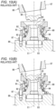
- FIGS. 10 (A) and 10 (B) are explanatory views showing a process of fixing the inner ring member 96 to the shaft main body 94 by the swaged portion 98 using the manufacturing device.
- the inner shaft 93 is fixed to the fixing stage 98 .
- the swaged portion 98 has a shape of cylinder extending in the axial direction from the end portion 95 of the shaft main body 94 with a center axis C 1 of the shaft main body 94 as a center.
- the swaging mechanism 86 approaches (is descended to) the hub unit 90 which has been fixed to the fixing stage 89 , and the punch 88 is brought into contact with the swaged portion 98 while rotating the spindle 87 about the center axis C 1 using the electric motor 84 (see FIG. 9 ).
- the swaged portion 98 having a shape of cylinder is pressed by the punch 88 , so that its diameter is gradually expanded.
- the inner ring member 96 is restricted shaft main body in the axial direction by the swaged portion 98 whose diameter has been expanded as described above and is fixed to the shaft main body 94 .
- Patent Document 1 JP-A-2012-45612
- the swaging mechanism 86 is provided above the hub unit 90 fixed to the fixing stage 89 , and further, the hydraulic cylinder 82 of the thrust generating mechanism 83 and the rotating mechanism 85 including the electric motor 84 are provided thereabove. Therefore, when a processing area K 1 on the fixing stage 89 is set at a height (for example, a height of 1 m from the floor) to facilitate a work of an operator such as setting the hub unit 90 on the manufacturing device or taking out the processed hub unit 90 , there is a problem that the entire size of the device in height becomes large, thereby leading to the increase in size of the manufacturing device.
- a height for example, a height of 1 m from the floor
- an aspect of the present invention is to provide a manufacturing device capable of achieving the reduction in size, and a method for manufacturing a bearing unit by the manufacturing device which has achieved the reduction in size.
- a bearing unit manufacturing device for manufacturing a bearing unit, the bearing unit including an outer ring and an inner shaft disposed on a radially inner side of the outer ring via a rolling element, the inner shaft including a shaft main body and an inner ring member which is outwardly fitted onto an end portion of the shaft main body on one side in an axial direction and fixed by a swaged portion extending from the end portion, the bearing unit manufacturing device including: a rotating mechanism including a rotor which holds the other side of the inner shaft in the axial direction from below and rotates the inner shaft about a center axis of the inner shaft while the center axis is aligned with an up-down direction, the rotor being mounted below a processing area of the bearing unit; and a swaging mechanism mounted above the processing area and including a punch which is brought into contact with the swaged portion to plastically deform the swaged portion.
- the processing area of the bearing unit when the processing area of the bearing unit is set at a height to facilitate a work of an operator such as setting the bearing unit on the manufacturing device or taking out the processed bearing unit, the rotor is positioned below the processing area, and the swaging mechanism is positioned above the processing area, whereby it is possible to reduce the size of the manufacturing device in height so as to be less than that of the related art and to make the manufacturing device smaller.
- the manufacturing device further includes a thrust generating mechanism which generates a thrust for pressing the punch to the swaged portion, and the thrust generating mechanism includes an electric motor and a linear actuator which outputs a rotating force of the electric motor as an axial force.
- the thrust generating mechanism may be constituted by hydraulic equipment including a hydraulic unit and a hydraulic cylinder, but electric power consumption is smaller when the thrust generating mechanism is configured to have the electric motor and the linear actuator reduces electricity consumption.
- the electric power consumption becomes large since it is necessary to actuate the hydraulic unit even during an idling time when the processing of the swaged portion is not actually performed, whereas, in a case where the electric motor is employed, such an electric power consumption that is caused by flowing a standby current is sufficient during the idling time, which makes it possible to save energy.
- the linear actuator is provided in a region adjacent to the fixed spindle in a horizontal direction of the fixed spindle.
- the linear actuator and the fixed spindle are configured to be provided in parallel to each other, and it is possible to further effectively prevent the manufacturing device from becoming tall and increasing in size.
- the swaging mechanism further includes: a fixed spindle whose rotation is constrained; and a bearing portion which supports the punch to be rotatable about a center axis of the punch with respect to the fixed spindle.
- a fixed spindle whose rotation is constrained
- a bearing portion which supports the punch to be rotatable about a center axis of the punch with respect to the fixed spindle.
- a bearing unit manufacturing method for manufacturing a bearing unit including an outer ring and an inner shaft disposed on a radially inner side of the outer ring via a rolling element, the inner shaft including a shaft main body and an inner ring member which is outwardly fitted onto an end portion of the shaft main body on one side in an axial direction and fixed by a swaged portion extending from the end portion, the bearing unit manufacturing method including: rotating a rotor about a center axis of the inner shaft in a state in which the rotor holds the other side of the inner shaft in the axial direction from below while the center axis is aligned with an up-down direction; and plastically deforming the swaged portion by bringing a punch into contact with the swaged portion from above.
- the swaging processing is performed while the punch is installed above a processing area of the bearing unit and the rotor for rotating the inner shaft is installed below the processing area.
- the processing area is set at a height to facilitate a work of an operator such as setting the bearing unit on the manufacturing device or taking out the processed bearing unit
- the rotor is positioned below the processing area
- the swaging mechanism is positioned above the processing area, whereby it is possible to reduce the size of the manufacturing device in height so as to be less than that of the related art and to make the manufacturing device smaller.
- FIG. 1 is a cross-sectional view showing an example of a bearing unit manufactured by a manufacturing device according to an embodiment of a present invention.
- FIG. 2 is a cross-sectional view showing a portion of the bearing unit (hub unit).
- FIG. 3 is a side view showing an example of a manufacturing device according to an embodiment of a present invention.
- FIG. 4 is a perspective view of a hub unit mounted on a rotor.
- FIG. 5 is an explanatory view showing a modification example of a fixing unit.
- FIG. 6 is an explanatory view showing a hub unit fixed on a rotor, a swaging mechanism, and a constraint mechanism.
- FIG. 7 is an explanatory view showing a hub unit fixed on a rotor, a swaging mechanism, and a constraint mechanism.
- FIG. 8 is a cross-sectional view of a hub unit for describing a related art.
- FIG. 9 is a side view of a manufacturing device of a related art.
- FIGS. 10 (A) and 10 (B) are explanatory views showing a process of fixing an inner ring member to a shaft main body by a swaged portion using a manufacturing device of a related art.
- FIG. 1 is a cross-sectional view showing an example of a bearing unit manufactured by a manufacturing device according to an embodiment of a present invention.
- the bearing unit shown in FIG. 1 is a unit for rotatably supporting a vehicle wheel to a suspension device of a vehicle body side in a vehicle, and is called as a hub unit.
- the bearing unit which is manufactured will be described while being called as the hub unit 50 .
- the hub unit 50 includes an outer ring 51 fixed to the suspension device (not shown), and an inner shaft (hub shaft) 53 disposed on a radially inner side of the outer ring 51 via two rows of balls (rolling element) 52 .
- the inner shaft 53 includes a shaft main body 54 , and an inner ring member 56 outwardly fitted onto an end portion 55 of the shaft main body 54 on one side in an axial direction (right side in FIG. 1 ).
- the shaft main body 54 includes a flange portion 57 on the other side in the axial direction (on the left side in FIG. 1 ), and a wheel or a brake disc of the vehicle wheel (not shown) is attached to the flange portion 57 .
- the shaft main body 54 includes a stepped surface 59 facing toward the one side in the axial direction and provided at its middle portion in the axial direction.
- the stepped face 59 is formed in an annular shape, and a portion (an end portion 55 ) of the shaft main body 54 located further to the one side in the axial direction than this stepped face 59 (excluding a swaged portion 58 ) has a smaller outer diameter.
- the inner ring member 56 is outwardly fitted onto this end portion 55 while the inner ring member is in contact with the stepped face 59 . Further, the inner ring member 56 is prevented from being removed and dropping out in the one side of the axial direction by the swaged portion 58 which is extended toward a radially outside from the end portion 55 .
- the inner ring member 56 is fixed to the shaft main body 54 by being interposed in the axial direction between the stepped face 59 and the swaged portion 58 .
- the fixing of the inner ring member 56 by such swaged portion 58 is performed by the manufacturing device 10 shown in FIG. 3 .
- the hub unit 50 before the fixing of the inner ring member 56 to the shaft main body 54 by the manufacturing device 10 (intermediate product) is, as shown in FIG. 2 , in a state where the outer ring 51 is assembled outwardly onto the shaft main body 54 in the radial direction with the balls 52 interposed therebetween and the swaged portion 58 extends in the axial direction from the end portion 55 of the shaft main body 54 on the one side in the axial direction to have a cylindrical shape with a center axis C 1 of the shaft main body 54 as its center. Then the inner ring member 56 is outwardly fitted onto this end portion 55 . From this state, a punch 27 (see FIG.
- the inner ring member 54 can be fixed to the inner ring member 56 .
- FIG. 3 is a side view showing an example of the manufacturing device according to the embodiment of the present invention.
- the manufacturing device 10 includes a rotating mechanism 11 and a swaging mechanism 12 . Further, the manufacturing device 10 of the embodiment includes a thrust generating mechanism 13 and a constraint mechanism 14 .
- the rotating mechanism 11 , the swaging mechanism 12 , the thrust generating mechanism 13 , and the constraint mechanism 14 are mounted on a device frame 15 which is installed on a floor surface.
- a processing area (installation area) K 1 of the hub unit 50 (intermediate product) is set at a height (for example, 1 m from the floor) to facilitate a work of an operator such as setting the hub unit 50 (intermediate product) on the manufacturing device or taking out the hub unit 50 which has been processed.
- the hub unit 50 (intermediate product) is mounted on a rotor 21 which the rotating mechanism 11 has, with a posture where a center axis C 0 of the inner shaft 53 lies along an up-down direction with the swaged portion 58 upward and the flange portion 57 downward.
- the rotating mechanism 11 includes an electric motor 25 and a power transmission unit 26 besides the rotor 21 on which the hub unit 50 is placed and fixed, wherein the rotating force of the electric motor 25 is transmitted to the rotor 21 through the power transmission unit 26 , and the rotor 21 rotates about a reference axis (reference line) Z of the up-down direction.
- the hub unit 50 is mounted on the rotor 21 with the center axis C 0 of the inner shaft (the center axis C 1 of the shaft main body 54 ) aligned with the reference axis Z.
- the power transmission unit 26 can be constituted by a pulley or a belt, or constituted by gears, and has a function of decreasing a speed of rotation of the electric motor 25 .
- FIG. 4 is a perspective view of the hub unit 50 mounted on the rotor 21 . Further, in FIG. 4 , the outer ring 51 , the balls 51 and the inner ring member 56 of the hub unit 50 are omitted for convenience of explanation.
- the rotating mechanism 11 includes a fixing unit 22 for fixing the hub unit 50 to the rotor 21 .
- the fixing unit 22 shown in FIG. 4 includes a clamping member 23 which clamps the flange portion 57 of the shaft main body 54 between the rotor 21 and the clamp member in the up-down direction. With this configuration, it becomes possible to fix the shaft main body 54 to the rotor 21 and rotate the shaft main body 54 as one body with the rotor 21 even when the flange portion 57 has a cross shape as shown in FIG. 4 other than a circular shape.
- FIG. 5 is an explanatory view showing a modification example of the fixing unit 22 .
- the shaft main body 54 of the tub unit 50 includes a cylindrical portion 60 protruding in the axial direction in an inner circumference side portion of the flange portion 57 .
- the cylindrical portion 60 has a cylindrical shape with the center axis C 1 of the shaft main body 54 as the center, and is integrated with the shaft main body 54 .
- the fixing unit 22 shown in FIG. 5 includes a chuck (collet chuck) 24 provided to be rotatable as one body with the rotor 21 , and this chuck 24 fixes the shaft main body 54 to the rotor 21 by being put on the cylindrical portion 60 from the radial direction. As a result, it becomes possible to rotate the shaft main body 54 and the rotor 21 as one body.
- the fixing unit 22 can have a configuration other than that shown in FIGS. 4 and 5 .
- a pin member (not shown) which is integrated with the rotor 21 may be additionally provided to the said configuration, so that the rotating force of the rotor 21 is transmitted to the shaft main body 54 via the pin member by bringing the pin member in contact with a side surface 61 of the flange portion 57 .
- the pin member which is integrated with the rotor 21 may be configured to be inserted through a hole (for example, a hole for work) (not shown) formed in the flange portion 57 , so that the rotating force of the rotor 21 is transmitted to the shaft main body 54 via the pin member.
- the rotating mechanism 11 includes the rotor 21 , and the rotor 21 holds the other side of the inner shaft 53 in the axial direction (the flange portion 57 side) from below while the center axis C 0 of the inner shaft 53 of the hub unit 50 is aligned with the up-down direction.
- the rotor 21 can rotate the inner shaft 53 around the center axis C 0 by rotating itself.
- the rotor 21 is installed below the processing area K 1 of the hub unit 50 .
- the electric motor 25 and the power transmission unit 26 for rotating the rotor 21 around the reference axis Z are also installed at a region lower than the processing area K 1 .
- FIGS. 6 and 7 are explanatory views showing the hub unit 50 fixed on the rotor 21 , the swaging mechanism 12 , and the constraint mechanism 14 .
- the swaging mechanism 12 includes the punch 27 , the fixed spindle 28 , and the bearing portion 29 which supports the punch 27 with respect to the fixed spindle 28 .
- the swaging mechanism 12 is installed above the processing area K 1 .
- the manufacturing device 10 includes an ascending and descending frame 30 which is supported at a device frame 15 so as to be movable up and down.
- the fixed spindle 28 shown in FIG. 6 is attached to the ascending and descending frame 30 , and the fixed spindle 28 is ascended and descended by a linear actuator 33 of a thrust generating mechanism 13 (see FIG. 3 ) to be described below.
- the fixed spindle 28 is configured by a column-shaped member whose center is set at the reference axis (reference line) Z of the manufacturing device 10 .
- the fixed spindle 28 can be moved in the up-down direction together with the ascending and descending frame 30 , but its rotation is constrained by the ascending and descending frame 30 and the device frame 15 . That is, the fixed spindle 28 is movable in the up-down direction along the reference axis Z, but cannot be rotated about the reference axis Z.
- a hole 31 open downward is formed.
- a center axis (center line) C 2 of the hole 31 is inclined at a predetermined angle with respect to the reference axis Z.
- the punch 27 of a column shape is provided in the hole 31 with the bearing portion 29 interposed therebetween.
- the bearing portion 29 is a rolling bearing, and can support the punch 27 with respect to the fixed spindle 28 , thereby allowing the punch to be rotatable about the center axis (C 2 ).
- the center axis C 2 of the hole 31 becomes the center axis of the punch 27 , and the punch 27 can be freely rotated (spinning) about the center axis C 2 .
- the thrust generating mechanism 13 is configured to have an electric motor (servo motor) 32 , and the linear actuator 33 which outputs the rotating force of the electric motor 32 as an axial force.
- the linear actuator 33 of the embodiment is one having a ball screw mechanism, and the linear actuator 33 is mounted on the device frame 15 with a linear operation direction of the linear actuator 33 , that is, a longitudinal direction of the ball screw mechanism as the up-down direction.
- the ascending and descending frame 30 is attached to a nut unit (movable unit) 34 in which this ball screw mechanism (linear actuator 33 ) is mounted.
- the linear actuator 33 (ball screw mechanism) is provided in a region S 1 adjacent to the fixed spindle 28 in the horizontal direction of the fixed spindle 28 as shown in FIG. 3 .
- the thrust generating mechanism 13 can position the swaging mechanism 12 at a waiting position above the processing area K 1 by ascending the ascending and descending frame 30 (state shown in FIG. 6 ), and can also position the swaging mechanism 12 at a processing position in which the punch 27 is in contact with the swaged portion 58 of the hub unit 50 , by descending the ascending and descending frame 30 (state shown in FIG. 7 ). Further, the thrust generating mechanism 13 can apply a force directed downward to the swaging mechanism 12 , and thereby it becomes possible to generate a thrust for pressing the punch 27 onto the swaged portion 58 .
- the constraint mechanism 14 suppresses such deformation.
- the constraint mechanism 14 includes a ring member 35 which is brought in contact with a portion of outer circumferential surface of the inner ring member 56 .
- the ring member 35 has a high stiffness, and prevents the deformation of the inner ring member 56 .
- the ring member 35 is also made freely rotatable.
- the constraint mechanism 14 includes a rolling bearing 36 which rotatably supports the ring member 35 .
- the constraint mechanism 14 is also configured to be ascended and descended, and descends the ring member 35 to be fitted onto the inner ring member 56 when the hub unit 50 is fixed to the processing area K 1 .
- the hub unit 50 is fixed on the rotor 21 as shown in FIG. 6 , the swaging mechanism 12 is descended from the waiting position, and the rotor 21 (hub unit 50 ) is rotated about the center axis C 0 .
- the punch 27 is descended with an inclined state, and is not rotated until being brought into contact with the swaged portion 58 .
- the swaging mechanism 12 continues to be descended, and when the punch 27 is brought into contact with the swaged portion 58 , the punch 27 in contact with the swaged portion 58 is rotated accompanying (performs the accompanying rotation of) the shaft main body 54 with the center axis C 2 as a center since the hub unit 50 (shaft main body 54 ) is rotated together with the rotor 21 .
- the thrust generating mechanism 13 causes the punch 27 to press the swaged portion 58 .
- the punch 27 presses the swaged portion 58 which is rotated while the shaft main body 54 continues to be rotated, and thus the swaged portion 58 which has been in the cylindrical shape (see FIG. 2 ) is gradually and plastically deformed to expand its diameter (see FIG. 7 ).
- the punch 27 is supported so as to be rotatable about the center axis C 2 by the bearing portion 29 configured with the rolling bearing with respect to the fixed spindle 28 which is in a rotation-constrained state. Therefore, when the punch 27 is brought into contact with the inner shaft 53 (swaged portion 58 of the shaft main body 54 ) while the inner shaft 53 (shaft main body 54 ) is rotated by the rotating mechanism 11 , as described above, the punch 27 is rotated accompanying the inner shaft 53 which is rotated. As a result, it is possible to perform smoothly the plastic deformation of the swaged portion 58 by the punch 27 which is rotated.
- the ring member 35 of the constraint mechanism 14 is fitted onto a portion of the inner ring member 56 and prevents the deformation of the inner ring member 56 .
- the inner ring member 56 is fixed to the shaft main body 54 by the swaged portion 58 whose leading end has been subjected to the diameter expansion.
- the center axis C 0 of the inner shaft 53 of the hub unit 50 is aligned with the up-down direction, the flange portion 57 side (the other side in the axial direction) of the inner shaft 53 is held from the bottom, the rotor 21 is rotated about the center axis C 0 (see FIG. 6 ), and the punch 27 is brought into contact with the swaged portion 58 from the above, so that the swaged portion 58 is plastically deformed (see FIG. 7 ).
- the swaging processing is preformed while the punch 27 is installed above the processing area K 1 of the hub unit 50 and the rotor 21 for rotating the inner shaft 53 of the hub unit 50 is installed below the processing area K 1 . Therefore, when the processing area K 1 is set at a height (for example, height of 1 m from the floor) to facilitate a work of an operator such as setting the hub unit 50 in the manufacturing device 10 or taking the processed hub unit 50 out, the rotor 21 is positioned below the processing area K 1 , and the swaging mechanism 12 is positioned above the processing area K 1 . As a result, it is possible to reduce the size of the manufacturing device 10 in height so as to be less than that of the related art (see FIG. 9 ), and to make the manufacturing device 10 smaller.
- a height for example, height of 1 m from the floor
- the linear actuator (ball screw mechanism) 33 included in the thrust generating mechanism 13 is provided at the region S 1 adjacent to the fixed spindle 28 of the rotating mechanism 11 in the horizontal direction.
- the linear actuator 33 and the fixed spindle 28 are configured to be provided in parallel to each other. Accordingly, it is possible to further effectively prevent the manufacturing device 10 from becoming tall and increasing in size.
- the thrust generating mechanism 13 of the embodiment is configured to include the electric motor 32 and the linear actuator 33 .
- the thrust generating mechanism 13 may be configured with a hydraulic equipment including a hydraulic cylinder and a hydraulic unit, and however the electric power consumption becomes large in this case since it is necessary to actuate the hydraulic unit even during an idling time when the processing of the swaged portion 58 of the hub unit 50 is not actually performed.
- the thrust generating mechanism 13 includes the electric motor 32 as the power source, and thus such an electric power consumption that is caused by flowing a standby current is sufficient during the idling time, which makes it possible to save energy.
- a first pulley 26 b is attached to a lower portion of an output shaft 26 a of the power transmission unit 26 connected with the rotor 21 .
- a second pulley 26 c is attached to an output shaft 25 a of the electric motor 25 .
- a belt 26 d is stretched around these pulleys 26 b and 26 c , and the electric motor 25 is disposed adjacent a housing 26 e which supports the output shaft 26 a , in the horizontal direction.
- the manufacturing device of the invention is not limited to the embodiments shown in the drawings, and may be different embodiments within the scope of the invention.
- the rotating mechanism 11 may have a configuration other than the illustrated one.
Applications Claiming Priority (4)
| Application Number | Priority Date | Filing Date | Title |
|---|---|---|---|
| JP2017-138106 | 2017-07-14 | ||
| JP2017138106A JP6974971B2 (ja) | 2017-07-14 | 2017-07-14 | 軸受ユニットの製造装置及び軸受ユニットの製造方法 |
| JPJP2017-138106 | 2017-07-14 | ||
| PCT/JP2018/026022 WO2019013203A1 (ja) | 2017-07-14 | 2018-07-10 | 軸受ユニットの製造装置及び軸受ユニットの製造方法 |
Publications (2)
| Publication Number | Publication Date |
|---|---|
| US20200158180A1 US20200158180A1 (en) | 2020-05-21 |
| US11619268B2 true US11619268B2 (en) | 2023-04-04 |
Family
ID=65001720
Family Applications (1)
| Application Number | Title | Priority Date | Filing Date |
|---|---|---|---|
| US16/629,662 Active 2039-09-16 US11619268B2 (en) | 2017-07-14 | 2018-07-10 | Bearing unit manufacturing device and bearing unit manufacturing method |
Country Status (6)
| Country | Link |
|---|---|
| US (1) | US11619268B2 (zh) |
| JP (1) | JP6974971B2 (zh) |
| KR (1) | KR102343767B1 (zh) |
| CN (1) | CN110891708B (zh) |
| DE (1) | DE112018003620B4 (zh) |
| WO (1) | WO2019013203A1 (zh) |
Citations (18)
| Publication number | Priority date | Publication date | Assignee | Title |
|---|---|---|---|---|
| EP0014570B1 (en) | 1979-02-01 | 1982-12-29 | The City University | Rotary forging machine |
| WO1998025772A1 (en) | 1996-12-10 | 1998-06-18 | Kelsey Hayes Company | Vehicle wheel hub and bearing retention system and method for producing same |
| WO1998058762A1 (en) | 1997-06-24 | 1998-12-30 | The Timken Company | Process and machine for uniting rotatable machine components |
| US20010020329A1 (en) | 1998-06-22 | 2001-09-13 | Webb Alan Charles | Process and machine for uniting rotatable machine components |
| DE10017462A1 (de) | 2000-04-07 | 2001-10-18 | Fraunhofer Ges Forschung | Taumelpresse |
| US20020085781A1 (en) | 2000-12-18 | 2002-07-04 | Takeo Ohkuma | Rolling-bearing unit for wheel support |
| JP2002192385A (ja) | 2000-12-28 | 2002-07-10 | Unisia Jecs Corp | 電動式押圧装置 |
| JP2003021153A (ja) | 2001-07-05 | 2003-01-24 | Koyo Seiko Co Ltd | 軸受装置の組み立て方法 |
| JP2003028179A (ja) * | 2001-07-19 | 2003-01-29 | Nsk Ltd | 車輪支持用転がり軸受ユニットの製造方法及び製造装置 |
| US20120047740A1 (en) | 2010-08-30 | 2012-03-01 | Jtekt Corporation | Manufacturing method for vehicle hub unit |
| DE102012009545A1 (de) * | 2012-05-12 | 2013-11-14 | Daimler Ag | Verfahren zur Herstellung eines Rades |
| JP2014226679A (ja) | 2013-05-20 | 2014-12-08 | トヨタ自動車株式会社 | 塑性加工装置および塑性加工方法 |
| CN104550607A (zh) | 2014-12-26 | 2015-04-29 | 北京机电研究所 | 旋转锻压成形模具与旋转锻压成形方法 |
| US20160074928A1 (en) | 2014-09-15 | 2016-03-17 | Jtekt Corporation | Hub unit manufacturing apparatus |
| JP2016159337A (ja) | 2015-03-03 | 2016-09-05 | 新日鐵住金株式会社 | 回転鍛造方法、回転鍛造用金型および回転鍛造部品 |
| KR101677885B1 (ko) | 2015-04-29 | 2016-12-06 | 고진범 | 요크제조방법 |
| WO2016194866A1 (ja) * | 2015-06-05 | 2016-12-08 | 日本精工株式会社 | 車輪支持用転がり軸受ユニットの製造方法 |
| WO2018179192A1 (ja) * | 2017-03-29 | 2018-10-04 | 不二商事株式会社 | 車両用のハブベアリングの内輪拘束装置 |
Family Cites Families (3)
| Publication number | Priority date | Publication date | Assignee | Title |
|---|---|---|---|---|
| CN1006859B (zh) * | 1985-06-14 | 1990-02-21 | 海因里希·施米德 | 摆动辗压机摆头的传动装置 |
| JP2012197932A (ja) * | 2011-03-07 | 2012-10-18 | Jtekt Corp | 車輪用転がり軸受装置の製造方法 |
| JP2017138106A (ja) | 2016-02-01 | 2017-08-10 | 日立金属株式会社 | 表面欠陥判別方法 |
-
2017
- 2017-07-14 JP JP2017138106A patent/JP6974971B2/ja active Active
-
2018
- 2018-07-10 DE DE112018003620.0T patent/DE112018003620B4/de active Active
- 2018-07-10 WO PCT/JP2018/026022 patent/WO2019013203A1/ja active Application Filing
- 2018-07-10 KR KR1020207000692A patent/KR102343767B1/ko active IP Right Grant
- 2018-07-10 CN CN201880046333.4A patent/CN110891708B/zh active Active
- 2018-07-10 US US16/629,662 patent/US11619268B2/en active Active
Patent Citations (27)
| Publication number | Priority date | Publication date | Assignee | Title |
|---|---|---|---|---|
| EP0014570B1 (en) | 1979-02-01 | 1982-12-29 | The City University | Rotary forging machine |
| WO1998025772A1 (en) | 1996-12-10 | 1998-06-18 | Kelsey Hayes Company | Vehicle wheel hub and bearing retention system and method for producing same |
| US6443622B1 (en) | 1997-06-24 | 2002-09-03 | The Timken Company | Spindle and component assembly with formed spindle end portion |
| WO1998058762A1 (en) | 1997-06-24 | 1998-12-30 | The Timken Company | Process and machine for uniting rotatable machine components |
| US20020172439A1 (en) | 1997-06-24 | 2002-11-21 | Webb Alan Charles | Deformable spindle end portion |
| US20010020329A1 (en) | 1998-06-22 | 2001-09-13 | Webb Alan Charles | Process and machine for uniting rotatable machine components |
| US20020174544A1 (en) | 1998-06-22 | 2002-11-28 | Webb Alan Charles | Component assembly with formed spindle end portion |
| US20040165801A1 (en) | 1999-12-23 | 2004-08-26 | Webb Alan Charles | Component assembly with formed spindle end portion |
| DE10017462A1 (de) | 2000-04-07 | 2001-10-18 | Fraunhofer Ges Forschung | Taumelpresse |
| US20020085781A1 (en) | 2000-12-18 | 2002-07-04 | Takeo Ohkuma | Rolling-bearing unit for wheel support |
| JP2002250358A (ja) | 2000-12-18 | 2002-09-06 | Nsk Ltd | 車輪支持用転がり軸受ユニット |
| JP2002192385A (ja) | 2000-12-28 | 2002-07-10 | Unisia Jecs Corp | 電動式押圧装置 |
| JP2003021153A (ja) | 2001-07-05 | 2003-01-24 | Koyo Seiko Co Ltd | 軸受装置の組み立て方法 |
| JP2003028179A (ja) * | 2001-07-19 | 2003-01-29 | Nsk Ltd | 車輪支持用転がり軸受ユニットの製造方法及び製造装置 |
| US20120047740A1 (en) | 2010-08-30 | 2012-03-01 | Jtekt Corporation | Manufacturing method for vehicle hub unit |
| JP2012045612A (ja) | 2010-08-30 | 2012-03-08 | Jtekt Corp | 車両用ハブユニットの製造方法 |
| DE102012009545A1 (de) * | 2012-05-12 | 2013-11-14 | Daimler Ag | Verfahren zur Herstellung eines Rades |
| JP2014226679A (ja) | 2013-05-20 | 2014-12-08 | トヨタ自動車株式会社 | 塑性加工装置および塑性加工方法 |
| JP2016060267A (ja) | 2014-09-15 | 2016-04-25 | 株式会社ジェイテクト | ハブユニット製造装置 |
| US20160074928A1 (en) | 2014-09-15 | 2016-03-17 | Jtekt Corporation | Hub unit manufacturing apparatus |
| CN104550607A (zh) | 2014-12-26 | 2015-04-29 | 北京机电研究所 | 旋转锻压成形模具与旋转锻压成形方法 |
| JP2016159337A (ja) | 2015-03-03 | 2016-09-05 | 新日鐵住金株式会社 | 回転鍛造方法、回転鍛造用金型および回転鍛造部品 |
| KR101677885B1 (ko) | 2015-04-29 | 2016-12-06 | 고진범 | 요크제조방법 |
| WO2016194866A1 (ja) * | 2015-06-05 | 2016-12-08 | 日本精工株式会社 | 車輪支持用転がり軸受ユニットの製造方法 |
| US20180149206A1 (en) * | 2015-06-05 | 2018-05-31 | Nsk Ltd. | Manufacturing method for rolling bearing units for wheel support |
| WO2018179192A1 (ja) * | 2017-03-29 | 2018-10-04 | 不二商事株式会社 | 車両用のハブベアリングの内輪拘束装置 |
| US10914340B2 (en) * | 2017-03-29 | 2021-02-09 | Fuji Shoji Co., Ltd. | Inner-ring restraint device of hub bearing for vehicle |
Non-Patent Citations (8)
| Title |
|---|
| Apr. 6, 2021 Office Action issued in Japanese Patent Application No. 2017-138106. |
| Doege et al., "Forming Technology Handbook." Basics, Technologies, Machines, 3rd revised edition, 2016; pp. 828-829, 2016, Springer; Berlin, Germany. |
| Feb. 17, 2023 Office Action issued in German Patent Application No. 11 2018 003 620.0. |
| Machine Translation of DE 10 2012 009545 A1 (Year: 2013). * |
| Machine Translation of JP 2003-028179 A (Year: 2003). * |
| May 17, 2021 Office Action issued in Korean Patent Application No. 10-2020-7000692. |
| Sep. 25, 2018 Search Report issued in International Patent Application No. PCT/JP2018/026022. |
| Sep. 25, 2018 Written Opinion of the International Searching Authority issued in International Patent Application No. PCT/JP2018/026022. |
Also Published As
| Publication number | Publication date |
|---|---|
| KR102343767B1 (ko) | 2021-12-28 |
| JP2019018222A (ja) | 2019-02-07 |
| CN110891708A (zh) | 2020-03-17 |
| US20200158180A1 (en) | 2020-05-21 |
| DE112018003620B4 (de) | 2023-12-21 |
| JP6974971B2 (ja) | 2021-12-01 |
| CN110891708B (zh) | 2022-02-22 |
| WO2019013203A1 (ja) | 2019-01-17 |
| DE112018003620T5 (de) | 2020-05-14 |
| KR20200016963A (ko) | 2020-02-17 |
Similar Documents
| Publication | Publication Date | Title |
|---|---|---|
| CN104275495B (zh) | 一种汽车差速器壳体加工系统及加工方法 | |
| US9233443B2 (en) | Bearing preload structure of machine tool | |
| US20110000330A1 (en) | Ball nut of a ball screw | |
| US11619268B2 (en) | Bearing unit manufacturing device and bearing unit manufacturing method | |
| JP2008207259A (ja) | シールド取付け装置及びシールド取付け方法並びに当該方法によりシールドが取付けられた転がり軸受 | |
| JP4978888B2 (ja) | ボールねじ機構のねじ軸 | |
| EP3575012B1 (en) | Conveyance system, rocking-die forging method, rocking-die forging apparatus, bearing manufacturing method, vehicle manufacturing method, and machinery manufacturing method | |
| US11796006B2 (en) | Method for manufacturing hub unit bearing, swaging device, and method for manufacturing vehicle | |
| CN212734226U (zh) | 内直齿轮车床用节圆夹具 | |
| JP4811590B2 (ja) | 組付装置 | |
| JP2005195084A (ja) | 軸受装置のかしめ加工方法 | |
| JP2006132711A (ja) | 車輪支持用ハブユニットの製造方法 | |
| CN214769136U (zh) | 一种环形锻件环部轴孔加工装置 | |
| CN216290602U (zh) | 一种伺服电机定子精车双锥度治具 | |
| KR101432537B1 (ko) | 스러스트 에어포일 베어링의 탑포일 절곡방법 | |
| JP6840987B2 (ja) | ハブユニットの製造装置 | |
| JP2013244506A (ja) | チューブの加工装置及び加工方法 | |
| JPS6390332A (ja) | 等速自在継手外輪の加工方法およびその装置 | |
| JP2010195202A (ja) | 車輪支持用ハブユニットの軌道輪部材及びその製造方法 | |
| JP5146761B2 (ja) | 車輪用転がり軸受装置の製造方法 | |
| JP2008256019A (ja) | 車輪用転がり軸受装置及びその製造方法 | |
| JP5146070B2 (ja) | 金属製部材の塑性加工方法及び塑性加工装置 | |
| CN110625255A (zh) | 焊接夹具及焊接装置 | |
| JP2009185935A (ja) | 円錐ころ軸受、内輪構造体、および、円錐ころ軸受の組立方法 | |
| JP2009287594A (ja) | 転がり軸受装置及びその製造方法 |
Legal Events
| Date | Code | Title | Description |
|---|---|---|---|
| FEPP | Fee payment procedure |
Free format text: ENTITY STATUS SET TO UNDISCOUNTED (ORIGINAL EVENT CODE: BIG.); ENTITY STATUS OF PATENT OWNER: LARGE ENTITY |
|
| STPP | Information on status: patent application and granting procedure in general |
Free format text: DOCKETED NEW CASE - READY FOR EXAMINATION |
|
| AS | Assignment |
Owner name: JTEKT CORPORATION, JAPAN Free format text: CHANGE OF ADDRESS;ASSIGNOR:JTEKT CORPORATION;REEL/FRAME:060263/0275 Effective date: 20210707 |
|
| STPP | Information on status: patent application and granting procedure in general |
Free format text: NON FINAL ACTION MAILED |
|
| STPP | Information on status: patent application and granting procedure in general |
Free format text: RESPONSE TO NON-FINAL OFFICE ACTION ENTERED AND FORWARDED TO EXAMINER |
|
| STPP | Information on status: patent application and granting procedure in general |
Free format text: NOTICE OF ALLOWANCE MAILED -- APPLICATION RECEIVED IN OFFICE OF PUBLICATIONS |
|
| STCF | Information on status: patent grant |
Free format text: PATENTED CASE |