US10919081B2 - Punching method, punching device, and method for manufacturing laminated iron core - Google Patents
Punching method, punching device, and method for manufacturing laminated iron core Download PDFInfo
- Publication number
- US10919081B2 US10919081B2 US15/543,077 US201615543077A US10919081B2 US 10919081 B2 US10919081 B2 US 10919081B2 US 201615543077 A US201615543077 A US 201615543077A US 10919081 B2 US10919081 B2 US 10919081B2
- Authority
- US
- United States
- Prior art keywords
- steel sheets
- punching
- electrical steel
- sheet
- mold
- Prior art date
- Legal status (The legal status is an assumption and is not a legal conclusion. Google has not performed a legal analysis and makes no representation as to the accuracy of the status listed.)
- Active, expires
Links
- 238000004080 punching Methods 0.000 title claims abstract description 180
- 238000000034 method Methods 0.000 title claims abstract description 91
- XEEYBQQBJWHFJM-UHFFFAOYSA-N Iron Chemical group [Fe] XEEYBQQBJWHFJM-UHFFFAOYSA-N 0.000 title description 289
- 238000004519 manufacturing process Methods 0.000 title description 24
- 229910000976 Electrical steel Inorganic materials 0.000 claims abstract description 104
- 239000013078 crystal Substances 0.000 claims abstract description 54
- 229910000831 Steel Inorganic materials 0.000 claims description 190
- 239000010959 steel Substances 0.000 claims description 190
- 230000003068 static effect Effects 0.000 claims description 30
- 229910052782 aluminium Inorganic materials 0.000 claims description 12
- 229910052748 manganese Inorganic materials 0.000 claims description 10
- 238000003825 pressing Methods 0.000 claims description 3
- 229910052742 iron Inorganic materials 0.000 description 102
- 230000006866 deterioration Effects 0.000 description 76
- 239000011162 core material Substances 0.000 description 39
- 230000000052 comparative effect Effects 0.000 description 37
- 239000000463 material Substances 0.000 description 36
- 230000008569 process Effects 0.000 description 26
- 238000005520 cutting process Methods 0.000 description 19
- 230000003247 decreasing effect Effects 0.000 description 16
- 230000000694 effects Effects 0.000 description 16
- 230000002829 reductive effect Effects 0.000 description 7
- 238000010008 shearing Methods 0.000 description 6
- 239000011248 coating agent Substances 0.000 description 5
- 238000000576 coating method Methods 0.000 description 5
- 230000006872 improvement Effects 0.000 description 5
- 230000002265 prevention Effects 0.000 description 5
- 230000007423 decrease Effects 0.000 description 4
- 238000011156 evaluation Methods 0.000 description 4
- 230000010354 integration Effects 0.000 description 4
- 230000005389 magnetism Effects 0.000 description 4
- 229910052698 phosphorus Inorganic materials 0.000 description 4
- 239000002244 precipitate Substances 0.000 description 4
- 238000009825 accumulation Methods 0.000 description 3
- 239000000853 adhesive Substances 0.000 description 3
- 230000001070 adhesive effect Effects 0.000 description 3
- 239000000047 product Substances 0.000 description 3
- 230000009467 reduction Effects 0.000 description 3
- 229910052710 silicon Inorganic materials 0.000 description 3
- 238000003466 welding Methods 0.000 description 3
- 229910000576 Laminated steel Inorganic materials 0.000 description 2
- 229910000565 Non-oriented electrical steel Inorganic materials 0.000 description 2
- 238000005299 abrasion Methods 0.000 description 2
- 239000000654 additive Substances 0.000 description 2
- 230000000996 additive effect Effects 0.000 description 2
- 238000000137 annealing Methods 0.000 description 2
- 230000008901 benefit Effects 0.000 description 2
- 229910052804 chromium Inorganic materials 0.000 description 2
- 238000007872 degassing Methods 0.000 description 2
- 230000004907 flux Effects 0.000 description 2
- 238000005098 hot rolling Methods 0.000 description 2
- 238000010030 laminating Methods 0.000 description 2
- 238000005259 measurement Methods 0.000 description 2
- 239000011347 resin Substances 0.000 description 2
- 229920005989 resin Polymers 0.000 description 2
- 230000000007 visual effect Effects 0.000 description 2
- DBGSRZSKGVSXRK-UHFFFAOYSA-N 1-[2-[5-[2-(2,3-dihydro-1H-inden-2-ylamino)pyrimidin-5-yl]-1,3,4-oxadiazol-2-yl]acetyl]-3,6-dihydro-2H-pyridine-4-carboxylic acid Chemical compound C1C(CC2=CC=CC=C12)NC1=NC=C(C=N1)C1=NN=C(O1)CC(=O)N1CCC(=CC1)C(=O)O DBGSRZSKGVSXRK-UHFFFAOYSA-N 0.000 description 1
- PQVHMOLNSYFXIJ-UHFFFAOYSA-N 4-[2-(2,3-dihydro-1H-inden-2-ylamino)pyrimidin-5-yl]-1-[2-oxo-2-(2,4,6,7-tetrahydrotriazolo[4,5-c]pyridin-5-yl)ethyl]pyrazole-3-carboxylic acid Chemical compound C1C(CC2=CC=CC=C12)NC1=NC=C(C=N1)C=1C(=NN(C=1)CC(N1CC2=C(CC1)NN=N2)=O)C(=O)O PQVHMOLNSYFXIJ-UHFFFAOYSA-N 0.000 description 1
- 230000001133 acceleration Effects 0.000 description 1
- PNEYBMLMFCGWSK-UHFFFAOYSA-N aluminium oxide Inorganic materials [O-2].[O-2].[O-2].[Al+3].[Al+3] PNEYBMLMFCGWSK-UHFFFAOYSA-N 0.000 description 1
- 229910052787 antimony Inorganic materials 0.000 description 1
- 230000015572 biosynthetic process Effects 0.000 description 1
- 238000005097 cold rolling Methods 0.000 description 1
- 238000009749 continuous casting Methods 0.000 description 1
- 229910052802 copper Inorganic materials 0.000 description 1
- 229910052593 corundum Inorganic materials 0.000 description 1
- 239000006185 dispersion Substances 0.000 description 1
- 238000005530 etching Methods 0.000 description 1
- 230000005284 excitation Effects 0.000 description 1
- 238000003384 imaging method Methods 0.000 description 1
- 239000012535 impurity Substances 0.000 description 1
- 230000009191 jumping Effects 0.000 description 1
- 238000003475 lamination Methods 0.000 description 1
- 238000002156 mixing Methods 0.000 description 1
- 239000000203 mixture Substances 0.000 description 1
- 229910052758 niobium Inorganic materials 0.000 description 1
- 229910052757 nitrogen Inorganic materials 0.000 description 1
- 230000036961 partial effect Effects 0.000 description 1
- 230000002093 peripheral effect Effects 0.000 description 1
- 238000005554 pickling Methods 0.000 description 1
- 238000005498 polishing Methods 0.000 description 1
- 238000010992 reflux Methods 0.000 description 1
- 230000000452 restraining effect Effects 0.000 description 1
- 229910052711 selenium Inorganic materials 0.000 description 1
- 238000004904 shortening Methods 0.000 description 1
- 229910052717 sulfur Inorganic materials 0.000 description 1
- 229910052718 tin Inorganic materials 0.000 description 1
- 229910052719 titanium Inorganic materials 0.000 description 1
- 238000004804 winding Methods 0.000 description 1
- 229910001845 yogo sapphire Inorganic materials 0.000 description 1
Images


Classifications
-
- B—PERFORMING OPERATIONS; TRANSPORTING
- B21—MECHANICAL METAL-WORKING WITHOUT ESSENTIALLY REMOVING MATERIAL; PUNCHING METAL
- B21D—WORKING OR PROCESSING OF SHEET METAL OR METAL TUBES, RODS OR PROFILES WITHOUT ESSENTIALLY REMOVING MATERIAL; PUNCHING METAL
- B21D28/00—Shaping by press-cutting; Perforating
- B21D28/02—Punching blanks or articles with or without obtaining scrap; Notching
-
- B—PERFORMING OPERATIONS; TRANSPORTING
- B21—MECHANICAL METAL-WORKING WITHOUT ESSENTIALLY REMOVING MATERIAL; PUNCHING METAL
- B21D—WORKING OR PROCESSING OF SHEET METAL OR METAL TUBES, RODS OR PROFILES WITHOUT ESSENTIALLY REMOVING MATERIAL; PUNCHING METAL
- B21D28/00—Shaping by press-cutting; Perforating
-
- B—PERFORMING OPERATIONS; TRANSPORTING
- B21—MECHANICAL METAL-WORKING WITHOUT ESSENTIALLY REMOVING MATERIAL; PUNCHING METAL
- B21D—WORKING OR PROCESSING OF SHEET METAL OR METAL TUBES, RODS OR PROFILES WITHOUT ESSENTIALLY REMOVING MATERIAL; PUNCHING METAL
- B21D28/00—Shaping by press-cutting; Perforating
- B21D28/02—Punching blanks or articles with or without obtaining scrap; Notching
- B21D28/14—Dies
-
- B—PERFORMING OPERATIONS; TRANSPORTING
- B21—MECHANICAL METAL-WORKING WITHOUT ESSENTIALLY REMOVING MATERIAL; PUNCHING METAL
- B21D—WORKING OR PROCESSING OF SHEET METAL OR METAL TUBES, RODS OR PROFILES WITHOUT ESSENTIALLY REMOVING MATERIAL; PUNCHING METAL
- B21D28/00—Shaping by press-cutting; Perforating
- B21D28/02—Punching blanks or articles with or without obtaining scrap; Notching
- B21D28/22—Notching the peripheries of circular blanks, e.g. laminations for dynamo-electric machines
-
- B—PERFORMING OPERATIONS; TRANSPORTING
- B21—MECHANICAL METAL-WORKING WITHOUT ESSENTIALLY REMOVING MATERIAL; PUNCHING METAL
- B21D—WORKING OR PROCESSING OF SHEET METAL OR METAL TUBES, RODS OR PROFILES WITHOUT ESSENTIALLY REMOVING MATERIAL; PUNCHING METAL
- B21D35/00—Combined processes according to or processes combined with methods covered by groups B21D1/00 - B21D31/00
- B21D35/002—Processes combined with methods covered by groups B21D1/00 - B21D31/00
- B21D35/005—Processes combined with methods covered by groups B21D1/00 - B21D31/00 characterized by the material of the blank or the workpiece
-
- B—PERFORMING OPERATIONS; TRANSPORTING
- B21—MECHANICAL METAL-WORKING WITHOUT ESSENTIALLY REMOVING MATERIAL; PUNCHING METAL
- B21D—WORKING OR PROCESSING OF SHEET METAL OR METAL TUBES, RODS OR PROFILES WITHOUT ESSENTIALLY REMOVING MATERIAL; PUNCHING METAL
- B21D35/00—Combined processes according to or processes combined with methods covered by groups B21D1/00 - B21D31/00
- B21D35/002—Processes combined with methods covered by groups B21D1/00 - B21D31/00
- B21D35/005—Processes combined with methods covered by groups B21D1/00 - B21D31/00 characterized by the material of the blank or the workpiece
- B21D35/007—Layered blanks
-
- B—PERFORMING OPERATIONS; TRANSPORTING
- B26—HAND CUTTING TOOLS; CUTTING; SEVERING
- B26F—PERFORATING; PUNCHING; CUTTING-OUT; STAMPING-OUT; SEVERING BY MEANS OTHER THAN CUTTING
- B26F1/00—Perforating; Punching; Cutting-out; Stamping-out; Apparatus therefor
- B26F1/38—Cutting-out; Stamping-out
- B26F1/40—Cutting-out; Stamping-out using a press, e.g. of the ram type
- B26F1/42—Cutting-out; Stamping-out using a press, e.g. of the ram type having a pressure roller
-
- C—CHEMISTRY; METALLURGY
- C22—METALLURGY; FERROUS OR NON-FERROUS ALLOYS; TREATMENT OF ALLOYS OR NON-FERROUS METALS
- C22C—ALLOYS
- C22C38/00—Ferrous alloys, e.g. steel alloys
-
- C—CHEMISTRY; METALLURGY
- C22—METALLURGY; FERROUS OR NON-FERROUS ALLOYS; TREATMENT OF ALLOYS OR NON-FERROUS METALS
- C22C—ALLOYS
- C22C38/00—Ferrous alloys, e.g. steel alloys
- C22C38/06—Ferrous alloys, e.g. steel alloys containing aluminium
-
- H—ELECTRICITY
- H01—ELECTRIC ELEMENTS
- H01F—MAGNETS; INDUCTANCES; TRANSFORMERS; SELECTION OF MATERIALS FOR THEIR MAGNETIC PROPERTIES
- H01F1/00—Magnets or magnetic bodies characterised by the magnetic materials therefor; Selection of materials for their magnetic properties
- H01F1/01—Magnets or magnetic bodies characterised by the magnetic materials therefor; Selection of materials for their magnetic properties of inorganic materials
- H01F1/03—Magnets or magnetic bodies characterised by the magnetic materials therefor; Selection of materials for their magnetic properties of inorganic materials characterised by their coercivity
- H01F1/12—Magnets or magnetic bodies characterised by the magnetic materials therefor; Selection of materials for their magnetic properties of inorganic materials characterised by their coercivity of soft-magnetic materials
- H01F1/14—Magnets or magnetic bodies characterised by the magnetic materials therefor; Selection of materials for their magnetic properties of inorganic materials characterised by their coercivity of soft-magnetic materials metals or alloys
- H01F1/147—Alloys characterised by their composition
- H01F1/14708—Fe-Ni based alloys
- H01F1/14716—Fe-Ni based alloys in the form of sheets
-
- H—ELECTRICITY
- H01—ELECTRIC ELEMENTS
- H01F—MAGNETS; INDUCTANCES; TRANSFORMERS; SELECTION OF MATERIALS FOR THEIR MAGNETIC PROPERTIES
- H01F41/00—Apparatus or processes specially adapted for manufacturing or assembling magnets, inductances or transformers; Apparatus or processes specially adapted for manufacturing materials characterised by their magnetic properties
- H01F41/02—Apparatus or processes specially adapted for manufacturing or assembling magnets, inductances or transformers; Apparatus or processes specially adapted for manufacturing materials characterised by their magnetic properties for manufacturing cores, coils, or magnets
-
- H—ELECTRICITY
- H01—ELECTRIC ELEMENTS
- H01F—MAGNETS; INDUCTANCES; TRANSFORMERS; SELECTION OF MATERIALS FOR THEIR MAGNETIC PROPERTIES
- H01F41/00—Apparatus or processes specially adapted for manufacturing or assembling magnets, inductances or transformers; Apparatus or processes specially adapted for manufacturing materials characterised by their magnetic properties
- H01F41/02—Apparatus or processes specially adapted for manufacturing or assembling magnets, inductances or transformers; Apparatus or processes specially adapted for manufacturing materials characterised by their magnetic properties for manufacturing cores, coils, or magnets
- H01F41/0206—Manufacturing of magnetic cores by mechanical means
- H01F41/0233—Manufacturing of magnetic circuits made from sheets
-
- H—ELECTRICITY
- H01—ELECTRIC ELEMENTS
- H01F—MAGNETS; INDUCTANCES; TRANSFORMERS; SELECTION OF MATERIALS FOR THEIR MAGNETIC PROPERTIES
- H01F41/00—Apparatus or processes specially adapted for manufacturing or assembling magnets, inductances or transformers; Apparatus or processes specially adapted for manufacturing materials characterised by their magnetic properties
- H01F41/02—Apparatus or processes specially adapted for manufacturing or assembling magnets, inductances or transformers; Apparatus or processes specially adapted for manufacturing materials characterised by their magnetic properties for manufacturing cores, coils, or magnets
- H01F41/04—Apparatus or processes specially adapted for manufacturing or assembling magnets, inductances or transformers; Apparatus or processes specially adapted for manufacturing materials characterised by their magnetic properties for manufacturing cores, coils, or magnets for manufacturing coils
- H01F41/06—Coil winding
- H01F41/061—Winding flat conductive wires or sheets
-
- B—PERFORMING OPERATIONS; TRANSPORTING
- B21—MECHANICAL METAL-WORKING WITHOUT ESSENTIALLY REMOVING MATERIAL; PUNCHING METAL
- B21D—WORKING OR PROCESSING OF SHEET METAL OR METAL TUBES, RODS OR PROFILES WITHOUT ESSENTIALLY REMOVING MATERIAL; PUNCHING METAL
- B21D43/00—Feeding, positioning or storing devices combined with, or arranged in, or specially adapted for use in connection with, apparatus for working or processing sheet metal, metal tubes or metal profiles; Associations therewith of cutting devices
- B21D43/28—Associations of cutting devices therewith
- B21D43/287—Devices for handling sheet or strip material
-
- C—CHEMISTRY; METALLURGY
- C22—METALLURGY; FERROUS OR NON-FERROUS ALLOYS; TREATMENT OF ALLOYS OR NON-FERROUS METALS
- C22C—ALLOYS
- C22C38/00—Ferrous alloys, e.g. steel alloys
- C22C38/60—Ferrous alloys, e.g. steel alloys containing lead, selenium, tellurium, or antimony, or more than 0.04% by weight of sulfur
-
- H—ELECTRICITY
- H01—ELECTRIC ELEMENTS
- H01F—MAGNETS; INDUCTANCES; TRANSFORMERS; SELECTION OF MATERIALS FOR THEIR MAGNETIC PROPERTIES
- H01F1/00—Magnets or magnetic bodies characterised by the magnetic materials therefor; Selection of materials for their magnetic properties
- H01F1/01—Magnets or magnetic bodies characterised by the magnetic materials therefor; Selection of materials for their magnetic properties of inorganic materials
- H01F1/03—Magnets or magnetic bodies characterised by the magnetic materials therefor; Selection of materials for their magnetic properties of inorganic materials characterised by their coercivity
- H01F1/12—Magnets or magnetic bodies characterised by the magnetic materials therefor; Selection of materials for their magnetic properties of inorganic materials characterised by their coercivity of soft-magnetic materials
- H01F1/14—Magnets or magnetic bodies characterised by the magnetic materials therefor; Selection of materials for their magnetic properties of inorganic materials characterised by their coercivity of soft-magnetic materials metals or alloys
- H01F1/16—Magnets or magnetic bodies characterised by the magnetic materials therefor; Selection of materials for their magnetic properties of inorganic materials characterised by their coercivity of soft-magnetic materials metals or alloys in the form of sheets
-
- Y—GENERAL TAGGING OF NEW TECHNOLOGICAL DEVELOPMENTS; GENERAL TAGGING OF CROSS-SECTIONAL TECHNOLOGIES SPANNING OVER SEVERAL SECTIONS OF THE IPC; TECHNICAL SUBJECTS COVERED BY FORMER USPC CROSS-REFERENCE ART COLLECTIONS [XRACs] AND DIGESTS
- Y02—TECHNOLOGIES OR APPLICATIONS FOR MITIGATION OR ADAPTATION AGAINST CLIMATE CHANGE
- Y02T—CLIMATE CHANGE MITIGATION TECHNOLOGIES RELATED TO TRANSPORTATION
- Y02T10/00—Road transport of goods or passengers
- Y02T10/60—Other road transportation technologies with climate change mitigation effect
- Y02T10/64—Electric machine technologies in electromobility
Definitions
- the present invention relates to a punching method of an electrical steel sheet that is used for an iron core of a motor, a punching device, and a laminated iron core manufacturing method.
- the iron cores of the motors and the generators are manufactured by using, as a base material, an electrical steel sheet having a sheet thickness reduced for decreasing eddy current loss, and punching the electrical steel sheet.
- punching a mold for workpiece is installed in a press machine, respective parts of the iron core are punched out in the mold while a coil feeding device feeds out steel strips formed by slitting the steel sheet into predetermined widths.
- the iron core is manufactured by subjecting a plurality of iron core element pieces after the punching to interlocking in the mold for integration, or removing the iron core element pieces from the mold, and then, integrating them by welding or fixing with bolts.
- the iron core manufactured by laminating and integrating the thin electrical steel sheets in this manner is referred to as a laminated iron core.
- the above-mentioned punching is generally employed because it is excellent in productivity.
- the iron core element pieces need to be punched out one by one in a normal punching. Accordingly, when the sheet thickness of the base material is reduced, a large number of element pieces are required to manufacture the iron core and productivity is drastically lowered.
- Punching techniques in a state in which the base material steel sheets are stacked and solutions of problems related to the techniques are disclosed.
- Patent Literatures 1 and 2 disclose techniques of fixing a plurality of steel sheets using interlocking or the like in a process before punching at an early stage of a press process in a mold in order to address a problem of deviation among the steel sheets when the steel sheets are stacked and simultaneously fed into the mold.
- Patent Literature 3 discloses a technique of forming an integration locking portion for fixing steel sheets and flattening a projection of the integration locking portion using push back so as not to cause the projection shape from becoming an obstacle in a lamination process. All of these techniques disclose countermeasures against deterioration in dimensional accuracy when the steel sheets are simultaneously punched out.
- Patent Literatures 4 and 5 disclose techniques of enabling punching of a plurality of steel sheets to be simultaneously executed by one press process while preventing shear droop and burrs from being increased by a mold having a plurality of portions corresponding to punches and dies therein.
- Patent Literature 6 discloses that a plurality of steel sheets are bonded to each other while a crystal grain size is set to be 20 n ( ⁇ m) or more when n indicates the number of laminated sheets.
- Patent Literature 7 discloses a non-oriented electrical steel sheet for a rotor in order to prevent deterioration in magnetic characteristics of an iron core that occurs when a split iron core is manufactured.
- Patent Literature 1 Japanese Laid-open Patent Publication No. S55-156623
- Patent Literature 2 Japanese Laid-open Patent Publication No. 2003-153503
- Patent Literature 3 Japanese Laid-open Patent Publication No. 2005-261038
- Patent Literature 4 Japanese Laid-open Patent Publication No. 2012-115893
- Patent Literature 5 Japanese Laid-open Patent Publication No. 2012-115894
- Patent Literature 6 Japanese Laid-open Patent Publication No. 7-201551
- Patent Literature 7 Japanese Laid-open Patent Publication No. 2003-253404
- Patent Literatures 1 to 5 have focused attention on only deterioration in the dimensional accuracy of the iron core and increase in the amounts of the shear droop and the burrs due to the punching of the steel sheets and disclose no improvement solution related to the deterioration in the magnetic characteristics of the iron core.
- Patent Literatures 4 and 5 the stacked steel sheets are not simultaneously punched out by one mold. These techniques have an advantage from a viewpoint of the deterioration in the magnetic characteristics but have a disadvantage that the mold configuration is complicated and the mold cost is largely increased. Furthermore, these techniques do not disclose a method for efficiently integrating and binding a plurality of iron core element pieces provided by punching with the punches and dies.
- Patent Literature 6 has aimed at reduction in abrasion of a mold when the steel sheets are stacked and punched out and has not studied a solution for preventing the deterioration in the magnetic characteristics in the punching.
- the punching is performed in the state in which the steel sheets are bonded to each other and a process mode thereof is different from that in which the steel sheets are stacked immediately before being pressed and are subject to the punching.
- the technique disclosed in Patent Literature 7 has aimed at prevention of the deterioration in the magnetic characteristics of the iron core that occurs when the split iron core is manufactured and has not taken punching of a plurality of stacked steel sheets into consideration.
- the present invention has been made in view of the above-mentioned circumstances and an object thereof is to provide a punching method, a punching device, and a laminated iron core manufacturing method capable of simultaneously punching a plurality of stacked electrical steel sheets while decreasing deterioration in iron loss to the minimum.
- a punching method includes punching out a plurality of electrical steel sheets in a stacked state by a mold.
- Sheet thicknesses of the electrical steel sheets are set to be 0.35 mm or less, a Vickers hardness (test force 1 kg) of the sheets is set to be 150 to 400, and an average crystal grain size of the sheets is set to be 50 to 250 ⁇ m.
- a clearance of the mold is set to be 7% or more of a minimum sheet thickness of the sheet thicknesses of the electrical steel sheets and 7% or less of a total sheet thickness of the electrical steel sheets, and a pressure that a sheet presser of the mold applies to the electrical steel sheets is set to be 0.10 MPa or more.
- the sheet thicknesses of the electrical steel sheets are set to be 0.25 mm or less.
- a static friction coefficient between surfaces of the stacked electrical steel sheets is set to be 0.3 or more, and static friction coefficients between the electrical steel sheets and a surface of a die plate of the mold that makes contact with the electrical steel sheets and between the electrical steel sheets and a surface of the sheet presser of the mold are set to be 0.3 to 0.8.
- the electrical steel sheets contain Si of 0.5 to 6.6%, Al of 2.5% or less, and Mn of 0.1 to 3.0% in terms of mass ratio, and the number of inclusions having a grain size of 0.1 to 3.0 ⁇ m in steel is set to be in a range of 1000 to 8000 pieces/mm 2 .
- a punching device includes a mold, and the punching device is configured to punch a plurality of electrical steel sheets in a stacked state.
- Sheet thicknesses of the electrical steel sheets are set to be 0.35 mm or less, a Vickers hardness (test force 1 kg) of the sheets is set to be 150 to 400, and an average crystal grain size of the sheets is set to be 50 to 250 ⁇ m.
- a clearance of the mold is set to be 7% or more of a minimum sheet thickness of the sheet thicknesses of the electrical steel sheets and 7% or less of a total sheet thickness of the electrical steel sheets, and a pressure that a sheet presser of the mold applies to the electrical steel sheets is set to be 0.10 MPa or more.
- a laminated iron core manufacturing method includes laminating and integrating iron core element pieces punched using the punching method according to the above-described invention to manufacturing a laminated iron core.
- a plurality of stacked electrical steel sheets can be simultaneously punched out while decreasing deterioration in iron loss to the minimum.
- FIG. 1 is a schematic plan view for explaining the configuration of a punching device and the outline of punching process according to an embodiment of the invention.
- FIG. 2 is a view illustrating a laminated iron core that is manufactured in the embodiment.
- FIG. 3 is a view for explaining a method for evaluating magnetic characteristics (iron loss) of the laminated iron core that is manufactured in the embodiment.
- FIG. 4 is a graph illustrating a relation between a clearance and an iron loss deterioration ratio in a first example.
- FIG. 5 is a graph illustrating a relation between a sheet presser pressure and the iron loss deterioration ratio in the first example.
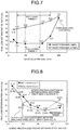
- FIG. 6 is a graph illustrating a relation between a hardness of electrical steel sheets and an iron loss deterioration ratio of a motor core in a second example.
- FIG. 7 is a graph illustrating a relation between a crystal grain size of the electrical steel sheets and the iron loss deterioration ratio of the motor core in the second example.
- FIG. 8 is a graph illustrating a relation between a static friction coefficient between electrical steel sheets and an iron loss deterioration ratio of a motor core in a third example.
- a punching device 10 includes a press machine 1 and pinch rolls 2 .
- a mold 3 used for punching that is installed in the press machine 1 includes a punch 4 and a die 5 .
- a die hole 6 as a through-hole having a shape corresponding to a shape of an iron core element piece to be molded and a die plate 7 making contact with a steel sheet are formed on the die 5 .
- the punch 4 is configured so as to be elevated and lowered relative to the die 5 by a control device (not illustrated).
- the mold 3 includes a sheet presser 8 to press the steel sheet in the vicinity of end portions thereof from the side of the punch 4 when punching, thereby pressing and restraining the steel sheet against and to the die plate 7 .
- a biasing unit 9 such as a spring is provided on the sheet presser 8 .
- the iron core element pieces are punched out while a plurality of steel strip coils C (C 1 to C 3 ) provided by cutting a steel sheet into predetermined widths are stacked and are fed out to the mold 3 by the pinch rolls (coil feeding device) 2 .
- the iron core element pieces after the punching process are subjected to interlocking in the mold 3 for integration, thereby manufacturing a laminated iron core.
- the laminated iron core is manufactured by removing the iron core element pieces from the mold 3 , and then, integrating them by welding or fixing with bolts.
- the present invention prevents deterioration in magnetic characteristics (iron loss) of the laminated iron core (hereinafter, also referred to as an iron core) in the punching of the electrical steel sheets (hereinafter, also referred to as steel sheets) stacked as described above.
- the inventors have focused on influence of a binding force applied between the stacked (laminated) steel sheets in the punching. Then, the inventors have considered that simultaneous control of both of conditions of the mold 3 and the material to be processed (steel sheet) can increase the binding force between the steel sheets and decrease the deterioration in the magnetic characteristics (iron loss) in the punching in the stacked state to the minimum, and have achieved the present invention.
- the individual steel sheets give influences on one another through surface friction in shearing process in the state where the steel sheets are stacked.
- the frictional force is insufficient to prevent the deterioration in the iron loss due to the punching.
- the inventors have considered that the frictional force between the steel sheet surfaces can be controlled appropriately by controlling the conditions of the mold 3 and the base material than conventional control more precisely.
- the inventors have focused on force that the sheet presser 8 applies to the steel sheets in the punching in order to improve the binding force using the frictional force between the steel sheet surfaces.
- the inventors have tried to control a friction coefficient between the steel sheet surfaces and a friction coefficient between the steel sheets and the surface of the mold 3 that makes contact therewith to be in appropriate ranges.
- the clearance a gives influence on the shape and characteristics of the material to be processed in the punching.
- the clearance a gives influence on the shape and characteristics of the material to be processed in the punching.
- the inventors have known that definition of the lower limit of the clearance a by a ratio relative to a sheet thickness of a steel sheet having a minimum sheet thickness among the steel sheets and definition of the upper limit thereof by a ratio relative to the total sheet thickness of the steel sheets are effective.
- the above-mentioned definition is considered to be effective because a strain manner of the end portions of the steel sheets when punching the laminated steel sheets is different from that in the punching one steel sheet.
- the punching process in the embodiment satisfies the following requirements defined based on the above-mentioned findings.
- the embodiment employs a wire cutting method as a work method for W 0 in the above-mentioned equation (1).
- the electrical steel sheet having the sheet thickness of 0.35 mm or less is used as the base material of the laminated iron core.
- the sheet thickness is increased to be larger than 0.35 mm, an advantage to be provided by the punching that is simultaneously performed on the steel sheets for improving production efficiency of the iron core is lowered.
- the total sheet thickness of two steel sheets or more is excessively large and it is difficult to keep dimensional accuracy of the iron core in the laminated state.
- preferable magnetic characteristics are not necessarily provided even by punching under other requirements, which will be described later.
- the sheet thicknesses of the steel sheets that are stacked are not necessarily the same and the steel sheets having different sheet thicknesses can be combined. In this case, it is sufficient that the thickness of the steel sheet having the largest sheet thickness is set to be 0.35 mm or less. As will be described in a second example later, the sheet thickness of the steel sheet that is used is desirably 0.25 mm or less.
- the clearance a gives influence on the shape of the punched end portions in the punching.
- the clearance a needs to be changed in accordance with the sheet thickness.
- the respective sheet thicknesses of the stacked steel sheets and a total value of the sheet thicknesses of the steel sheets are factors that can give influence on an appropriate value of the clearance a.
- the appropriate value of the clearance a needs to be defined in consideration of respective contributions.
- the lower limit of the clearance a is set to be 7% or more of the thickness of the steel sheet having the minimum sheet thickness among the stacked steel sheets based on a first example and the second example, which will be described later.
- a minimum value of the clearance a needs to be set in accordance with the sheet thickness of the steel sheet having the minimum sheet thickness (see, examples indicated in numbers 38, 39, 44, and 45 in Table 2 in the second example, which will be described later) in order to prevent the deterioration in the magnetic characteristics of the iron core.
- the clearance a needs to be set in this manner for the following reason. That is, in the punching of the multilayered steel sheets, a deviation amount (drawing amount) of the steel sheets in the vicinity of the punched end portions in the lateral direction is large and the steel sheet end portions are therefore easy to be deformed with elevation of the punch 4 . This influence becomes more significant in the steel sheet having the smaller sheet thickness and lower rigidity. Accordingly, in order to reduce the influence of the deformation that is received when the punch 4 is elevated due to the excessively small clearance a, the clearance a is set to be 7% or more of the sheet thickness of the steel sheet having the minimum sheet thickness among the steel sheets that are stacked.
- the upper limit of the clearance a is set to be 7% or less of the total thickness of the stacked steel sheets based on the first example and the second example, which will be described later. This is a necessary condition for preventing the deterioration in the iron loss by decreasing the deflection amount of the steel sheets to the minimum when the punching is performed on the stacked steel sheets.
- the embodiment employs a method of making the steel sheets be more close to be integrated by appropriately controlling the sheet presser 8 or the friction coefficient of the steel sheet surfaces as will be described later. In comparison with the punching to one steel sheet, a drawing amount of the steel sheets into the die hole 6 tends to be increased during the punching to the stacked steel sheets.
- a ratio of the clearance a relative to the total sheet thickness of the stacked steel sheets is set to be a value that is smaller than that of the clearance a when the steel sheets are regarded as one steel sheet.
- the sheet presser 8 of the mold 3 for the punching is used mainly for preventing jumping of the material to be punched in the punching.
- the sheet presser 8 is used for increasing the binding force in the vicinity of the end portions of the stacked steel sheets on which the shearing process is performed when the steel sheets are stacked and are subjected to the punching.
- the pressure (sheet presser pressure) that the sheet presser 8 applies to the steel sheets is set to be at least 0.10 MPa.
- the sheet presser pressure is lower than 0.10 MPa, the binding force between the steel sheets is lowered during the punching and the local deviation amount of the end portions during the punching is increased, resulting in the deterioration in the magnetic characteristics.
- the sheet presser pressure is preferably set to be in a range of 0.30 to 0.80 MPa based on the first example, which will be described later, in a further limited manner.
- An effect of increasing the binding force between the stacked steel sheets is enhanced particularly when the sheet presser pressure is set to be 0.30 MPa or more.
- the sheet presser pressure is higher than 0.80 MPa, it can be said that the binding force between the steel sheets is sufficiently high but the iron loss deterioration ratio is increased. As a reason for this, it is estimated that a speed at which a stripper plate of the sheet presser 8 and the steel sheets hit each other is increased when the punching is continuously performed to make strain easy to be generated in the steel sheets.
- the sheet presser 8 can have the above-mentioned functions by causing the sheet presser pressure to be applied to the local portions of the base material in the vicinity of the punch 4 during the punching.
- a force that the sheet presser 8 presses the material to be processed using the mold 3 is normally uniform over the entire surface of the stripper plate of the sheet presser 8 , and the force is therefore calculated by dividing a total value of the force acting on the sheet presser 8 by the area of the sheet presser 8 .
- Crystal Grain Size of Electrical Steel Sheets Average Crystal Grain Size of 50 to 250 ⁇ m
- the crystal grain size is an important factor dominating the magnetic characteristics of the non-oriented electrical steel sheets. It is generally known that as the crystal grain size is larger, the iron loss is more excellent. Influence by the crystal grain size of the electrical steel sheets that are subject to the punching to the deterioration in the magnetic characteristics of the iron core after the punching has not been well known (see Patent Literatures 6 and 7).
- the present invention controls the crystal grain size of the electrical steel sheets on which the punching is simultaneously performed to be in an appropriate range in addition to the requirements of the punching process in order to prevent the deterioration in the magnetic characteristics that are easy to occur when the punching is performed on the steel sheets in the stacked state.
- the binding force between the steel sheets is required to be increased with the sheet presser pressure, the frictional force between the steel sheet surfaces, and the like but only the increase in the binding force is not sufficient to prevent the deterioration in the iron loss in the iron core element pieces after the punching. That is to say, the drawing amount of the steel sheet having a relatively weak binding force among the stacked steel sheets into the die hole 6 with the lowering of the punch 4 is increased.
- the steel sheet is punched out in a state in which the elastic plastic deformation is generated in the end portions thereof, an accumulation amount of the strain on the end portions of the steel sheet after the punching is increased and the iron loss of the iron core is deteriorated.
- the accumulation amount of the strain due to the elastic plastic deformation is considered to be increased in accordance with increase in unevenness of mechanical characteristics in the base material. Grain boundary portions and inner portions of the crystal grains are roughly distributed in the steel sheet having a coarse crystal grain size. The deterioration in the iron loss is therefore considered to be significant in the punching in the state in which the steel sheets are stacked. On the other hand, the crystal grain boundaries are densely distributed in the steel sheet having a fine crystal grain size to cause the deformation to uniformly occur in the steel sheet, thereby preventing the deterioration in the iron loss.
- the sheet presser pressure is increased and the crystal grain size is set to 50 to 250 ⁇ m (more desirably 100 to 200 ⁇ m) based on the second example, which will be described later.
- the iron loss deterioration amount can be made small and the absolute value of the iron loss of the iron core after the punching can be made sufficiently decreased.
- the sheet presser pressure is not sufficient, the effect of decreasing the absolute value of the iron loss of the iron core cannot be sufficiently provided even by setting the crystal grain size to 50 to 250 ⁇ m (100 to 200 ⁇ m). That is to say, the desired effect is provided only by appropriately controlling both of the crystal grain size and the sheet presser pressure.
- the crystal grain size is increased to be larger than 200 ⁇ m or 250 ⁇ m, the amount of strain remaining in the end portions of the steel sheets is increased and the increase amount of the iron loss of the iron core is increased when the steel sheets are stacked and are subject to the punching.
- the upper limit of the crystal grain size is therefore set to 250 ⁇ m, and preferably 200 ⁇ m.
- the crystal grain size is smaller than 100 ⁇ m or 50 ⁇ m, the above-mentioned deterioration in the iron loss is avoided but the magnetic characteristics of the base material itself of the iron core is inferior and the absolute value of the iron loss of the manufactured iron core is therefore inferior. Accordingly, such a crystal grain size is not appropriate for a material for a high-efficient motor.
- the lower limit of the crystal grain size is set to be 50 ⁇ m, and preferably 100 ⁇ m.
- the average crystal grain size is calculated based on observation of the cross section of the steel sheets. That is to say, the crystal grain size is suitably evaluated with an imaging process by providing a sample cross section by cutting and polishing, and then, exposing the crystal grain boundaries by an etching process.
- the average crystal grain size is calculated as follows. First, the average area that the crystal grain occupies the cross section is provided by counting the number of crystal grains present in the observation area and dividing the observation area by the number of crystal grains. When the shape of the crystal grains is assumed to be circular, the average crystal grain size is calculated from the calculated average area of one crystal grain. When the average crystal grain size calculated by this method is 80 ⁇ m or less, the value is employed as the average crystal grain size.
- the above-mentioned method when the crystal grain size is coarse and the cross section contains partial fine crystal grains or cuts a portion around a grain boundary triple junction, the above-mentioned method generates errors in the calculation of the grain size.
- the average crystal grain size calculated by the above-mentioned method is larger than 80 ⁇ m, calculation involving weighting by the area ratios of the individual crystal grains observed in the cross section is suitable. That is to say, when the area of each crystal is assumed to be S(i) and the area ratio is assumed to be r(i), the average crystal grain area is expressed by the following equation (2).
- the average crystal grain size can be calculated as an equivalent circle diameter from the average crystal grain area.
- Hardness of Electrical Steel Sheets Vickers Hardness (test force 1 kg) of 150 to 400
- the drawing amount of the material to be processed into the die hole 6 is reduced and the accumulation amount of the strain in the vicinity of the worked end portions is decreased, thereby preventing the deterioration in the iron loss.
- the drawing amount of the material to be processed (steel sheets) into the die hole 6 is easy to be increased and the degree of importance for appropriately controlling the breakage of the material to be processed is extremely higher than that in the normal punching work.
- the conditions of the sheet presser 8 and the frictional force between the electrical steel sheet surfaces are simultaneously made appropriate to thereby increase the binding force between the electrical steel sheets to some degree.
- the hardness of the material is set to be in an appropriate range to cause the breakage during the punching to occur at appropriate positions, thereby preventing the deterioration in the iron loss.
- a significant effect of preventing the deterioration in the iron loss is provided by controlling the Vickers hardness of the base material to be in an appropriate range as indicated in the second example, which will be described later.
- the iron loss deterioration ratio when two electrical steel sheets or more are stacked and punched out is inferior to the iron loss deterioration ratio when one electrical steel sheet is punched out and improvement for this in the future is necessary.
- the hardness of the steel sheets can be evaluated by measuring the Vickers hardness and can be limited by a measurement value (HV 1 ) with a weight of 1 kg.
- the hardness of the electrical steel sheets is set to be the Vickers hardness of 150 or more.
- the steel sheets having the Vickers hardness of 190 or more are particularly suitable.
- the Vickers hardness of the steel sheets exceeds 400, it is disadvantageous from a view point of damage of the mold 3 . For this reason, the Vickers hardness of the steel sheets is limited to be 400 or more.
- the present invention uses the effect provided by increase in the binding force between the steel sheets when the stacked steel sheets are simultaneously punched out.
- the above-mentioned effect is provided by increasing the static friction coefficient of the steel sheet surfaces. That is to say, the static friction coefficient between the surfaces of the electrical steel sheets that are stacked and are subject to the punching is required to be controlled.
- the static friction coefficient between the stacked surfaces of the electrical steel sheets is preferably evaluated.
- the frictional forces particularly in the vicinity of the punch 4 on the surface of the die plate 7 and the surface of the sheet presser 8 that make contact with the electrical steel sheets on which the punching is performed are required to be simultaneously increased.
- the static friction coefficients between the electrical steel sheet surface and the surfaces of the above-mentioned members of the mold 3 need to be 0.3 or more. In order to provide the effect, the static friction coefficient of the mold 3 in a region of approximately 10 mm or more in the vicinity of the die hole 6 is required to be controlled.
- the above-mentioned effect can be provided by a method of changing roughness and so on in the region having a width of approximately 10 mm or more in the vicinity of the die hole 6 or the entire surfaces of the sheet presser 8 and the die plate 7 that make contact with the electrical steel sheets.
- the static friction coefficient between the steel sheet surfaces is set to be 0.3 or more and the static friction coefficients between the steel sheet surface and the mold member surfaces making contact with the steel surface are set to be 0.3 or more based on a third example, which will be described later.
- the static friction coefficients between the surface of the electrical steel sheets that are subject to the punching and the mold surfaces making contact with the surface of the electrical steel sheets are too high, the electrical steel sheets are not smoothly transported in the mold 3 , and the iron loss of the iron core after the punching is deteriorated.
- the static friction coefficients are limited to be 0.8 or less.
- contents of Si, Al, and Mn as steel components of the electrical steel sheets as the base material of the iron core are set to 0.5 to 6.6%, 2.5% or less, and 0.1 to 3.0%, respectively, in terms of mass ratio based on a fourth example, which will be described later.
- These contents of the steel components form a base satisfying the Vickers hardness of the material that is 150 or more and accelerates formation of the inclusions in the steel.
- the effects provided by the Vickers hardness are as described above. Effects provided by the inclusions in the steel will be described later.
- Si is an element that increases a specific resistance of the steel and thereby lowers eddy current loss to contribute to decrease in the iron loss.
- the additive amount (content) thereof is lower than 0.5% in terms of mass ratio, it is difficult to increase the Vickers hardness to be 150 or more without involving the deterioration of the iron loss of the material even when other components (Al, Cr, and the like) are added.
- the content of Si is therefore limited to be 0.5% or more.
- the content of Si is higher than 6.6% in terms of mass ratio, it is difficult to perform the punching in a state in which two sheets or more are stacked due to embrittlement of the base material.
- the content of Si is therefore limited to be 0.5 to 6.6% in terms of mass ratio.
- Al is an element that increases the specific resistance of the steel to contribute to decrease in the iron loss in the same manner as Si.
- Al forms inclusions such as AlN and Al 2 O 3 in the steel and contributes to acceleration of the breakage during the punching as will be described later.
- the content of Al is therefore limited to be 2.5% or less in terms of mass ratio.
- Mn has a function of increasing the specific resistance of the steel and preventing red embrittlement in hot rolling. Furthermore, Mn forms MnS in the steel and contributes to improvement in punching workability as will be described later. In order to provide these effects, the content of Mn needs to be set to be 0.1% or more in terms of mass ratio. When the content of Mn is higher than 3.0% in terms of mass ratio, lowering in a magnetic flux density becomes significant. The content of Mn is therefore limited to be 0.1 to 3.0% in terms of mass ratio.
- the number of inclusions having the grain size of 0.1 to 3.0 ⁇ m in the steel is set to 1000 to 8000 pieces/mm 2 based on the fourth example, which will be described later.
- This setting decreases the iron loss of the iron core after the punching. This is because when the steel sheets are drawn into the die hole 6 and are broken during the punching, the steel sheets are broken from the inclusions as crack generation origins at an early stage in the punching process and the amount of strain remaining in the iron core after the punching is decreased as in the study for the hardness of the steel sheets.
- the grain size and the number of inclusions are limited to be the above-mentioned ranges.
- the content of the precipitates can be calculated by observing the cross section (at approximately 1 ⁇ 4 sheet thickness) of the base material steel sheets, counting the grain size and the number of inclusions in an observation visual field, and dividing the number of inclusions in a region matching with the grain size range by the area of the observation visual field.
- the iron core element pieces provided by the punching process that satisfies the above-mentioned requirements are laminated and integrated with one another to manufacture a laminated iron core for a motor or a generator.
- a method for integrating the iron core element pieces there is a method (what is called in-mold interlocking) in which the iron core element pieces are separated from the base material after the punching in the mold 3 , and then, are subject to interlocking in the mold 3 lowered by the punch 4 .
- This method is excellent in manufacturing performance.
- a method in which only dowels for interlocking are formed in the punching process in the mold 3 and a device other than the mold 3 for punching applies pressure after the punching for interlocking may be employed.
- a method in which only the punching is performed in the mold 3 and the iron core element pieces are integrated with one another by welding, fixing with bolts, coating of an adhesive, or application of adhesive coating outside the mold 3 may be employed.
- a method in which an adhesive is applied to the electrical steel sheet surfaces and the iron core element pieces are made to adhere to each other and are punched instead of interlocking in the mold 3 can also be applied to the invention.
- Two steel strip coils for punching work that were provided by slitting an electrical steel sheet coil containing Si of 3.0%, Al of 0.8%, Mn of 0.7%, and P of 0.03% in terms of mass ratio in steel and having a sheet thickness of 0.25 mm so as to have widths of 160 mm were prepared as the base material steel sheets.
- the two steel strip coils (C 1 and C 2 ) were simultaneously subject to the punching using the punching device 10 illustrated in FIG. 1 (work method: punching of two stacked sheets).
- the iron core element pieces provided by the punching were subject to interlocking in the mold 3 to manufacture a stator iron core for a brushless DC motor (motor core) illustrated in FIG. 2 .
- the clearance (one side) a in the punching was made to vary in a range of 2 to 15% relative to the total sheet thickness of 0.50 mm of the two electrical steel sheets.
- the pressure (sheet presser pressure) that the sheet presser 8 applies to the electrical steel sheets in the mold 3 was made to vary in a range of 0.05 to 1.0 MPa.
- the Vickers hardness (test force 1 kg) of the used electrical steel sheets was set to 195, the average crystal grain size was set to 80 ⁇ m, the static friction coefficient between the steel sheets was set to 0.2, and the static friction coefficient between the steel sheets and the mold 3 (the sheet presser 8 and the die plate 7 ) was set to 0.25.
- a motor core having the same dimensions was manufactured by wire cutting (work method: wire cutting).
- a magnetic circuit was formed by winding a primary coil for excitation b 1 and a secondary coil for magnetic flux measurement b 2 around a core back portion as illustrated in FIG. 3 and the core iron loss was evaluated by measuring magnetism.
- Table 1 indicates the above-mentioned conditions and evaluation results of the core iron loss.
- FIG. 4 is a graph illustrating a relation between the clearance a of the mold 3 for the punching and the iron loss deterioration ratio expressed by the above-mentioned equation (1).
- the iron loss deterioration ratio was lowered with reduction in the clearance a.
- the iron loss deterioration ratio was significantly lowered when the clearance a was set to 3.5 to 7% of the total sheet thickness of the two electrical steel sheets. It was also found that in the case of the punching to two stacked sheets, the iron loss deterioration ratio was higher than that in the case of the punching to one sheet even under the above-mentioned conditions, resulting in that future challenges were left.
- FIG. 5 is a graph illustrating a relation between the sheet presser pressure and the iron loss deterioration ratio.
- the iron loss deterioration ratio hardly depends on the sheet presser pressure.
- the iron loss deterioration ratio was lowered when the sheet presser pressure was controlled to be in a range of 0.10 MPa or more (desirably 0.30 to 0.80 MPa).
- Steel strip coils for punching work that were provided slitting electrical steel sheet coils having different crystal grain sizes with varied contents of Si, Al, Mn, and P in steel and having sheet thicknesses of 0.35 mm, 0.25 mm, 0.20 mm, and 0.15 mm so as to have widths of 160 mm were prepared as the base material steel sheets.
- the two steel strip coils (C 1 and C 2 ) of a varied combination among them were simultaneously subject to the punching using the punching device 10 illustrated in FIG. 1 .
- Outer peripheral portions of the iron core element pieces provided by the punching were welded to manufacture a stator iron core for a brushless DC motor (motor core).
- the clearance (one side) a in the punching was set to 25 ⁇ m (5% of the total sheet thickness of the two sheets) and the pressure (sheet presser pressure) that the sheet presser 8 applies to the material in the mold 3 was set to 0.35 MPa.
- a motor core having the same dimensions as those in the example (inventive example) was manufactured by wire cutting (work method: wire cutting).
- the iron loss of the manufactured motor core was evaluated by simply measuring magnetism using the magnetic circuit illustrated in FIG. 3 .
- Table 2 indicates the above-mentioned conditions and evaluation results of the core iron loss.
- FIG. 6 is a graph illustrating a relation between the hardness of the electrical steel sheets and the iron loss deterioration ratio of the motor core.
- FIG. 7 is a graph illustrating a relation between the crystal grain size of the electrical steel sheets and the iron loss deterioration ratio of the motor core. It should be noted that the iron loss deterioration ratio in FIG. 6 and FIG. 7 indicates an increase ratio of the iron loss of the motor core (core iron loss) in the example relative to the iron loss of the motor core (wire cutting core iron loss) manufactured by wire cutting.
- the static friction coefficient was made to vary by causing compositions (resin blending ratio and wax addition amount) of chromic acid-resin based coating to vary.
- Three steel strip coils (C 1 to C 3 ) having widths of 160 mm were prepared from the electrical steel sheet coil. The three steel strip coils were simultaneously subject to the punching using the punching device 10 illustrated in FIG.
- the iron core element pieces provided by the punching were subject to interlocking in the mold 3 to manufacture a stator iron core for a brushless DC motor (motor core).
- the clearance (one side) a in the punching was set to 15 ⁇ m (4.3% of the total sheet thickness 0.35 mm), and the sheet presser pressure was set to 0.06 to 0.5 MPa.
- a motor core having the same dimensions as those in the example (inventive example) was manufactured by wire cutting (work method: wire cutting).
- the iron loss of the manufactured motor core was evaluated by simply measuring magnetism using the magnetic circuit illustrated in FIG. 3 .
- Table 3 indicates the above-mentioned conditions and evaluation results of the core iron loss.
- FIG. 8 is a graph illustrating a relation between the static friction coefficient between the steel sheets and the iron loss deterioration ratio of the motor core. As illustrated in Table 3 and FIG. 8 , it was found that in the example, the three steel sheets were simultaneously punched out and the iron loss deterioration ratio was therefore higher than that when the two steel sheets were simultaneously punched out but the iron loss deterioration ratio of the iron core manufactured by wire cutting was lowered by satisfying the requirements of the present invention. In particular, as illustrated in FIG.
- the iron loss deterioration ratio was stably lowered to be 21% or lower by setting the static friction coefficient between the steel sheets to be 0.3 or more and setting the static friction coefficient between the steel sheets and the mold 3 to be in a range of 0.3 to 0.8.
- the size and the number of inclusions in steel were adjusted by adjusting degassing process time and a molten steel refluxing speed when manufacturing a steel slab. Then, the contents of Si, Al, Mn, and other elements were adjusted by component adjustment in a degassing process. Subsequently, continuous casting, hot rolling, hot rolled sheet annealing and pickling, and cold rolling were performed and a sheet thickness was set to 0.15 mm. Thereafter, an electrical steel sheet coil was manufactured by finish annealing and coating application. Two steel strip coils (C 1 and C 2 ) having widths of 160 mm were prepared from the electrical steel sheet coil.
- the two steel strip coils were simultaneously subject to the punching using the punching device 10 illustrated in FIG. 1 (work method: punching of two stacked sheets).
- the iron core element pieces provided by the punching were subject to interlocking in the mold 3 to manufacture a stator iron core for a brushless DC motor (motor core).
- the clearance (one side) a in the punching was set to 12 ⁇ m (4% of the total sheet thickness of the two sheets) and the sheet presser pressure was set to 0.40 MPa.
- the ratio of the clearance a relative to the steel sheet having the minimum sheet thickness was 8% and the ratio of the clearance a relative to the total sheet thickness was 4%.
- the iron loss of the manufactured motor core was evaluated by simply measuring magnetism using the magnetic circuit illustrated in FIG. 3 .
- Table 4 indicates the above-mentioned conditions and evaluation results of the core iron loss.
- the laminated iron core for a high-efficient rotating equipment of a motor or a generator can be manufactured from an electrical steel sheet having a small sheet thickness highly efficiently.
- the punching method, the punching device, and the laminated iron core manufacturing method according to the present invention are useful for the punching to the steel sheet that is used for the iron core and manufacturing of the laminated iron core, and in particular, are suitable for the punching method, the punching device, and the laminated iron core manufacturing method capable of simultaneously punching a plurality of stacked electrical steel sheets while decreasing deterioration in iron loss to the minimum.
Landscapes
- Engineering & Computer Science (AREA)
- Mechanical Engineering (AREA)
- Chemical & Material Sciences (AREA)
- Power Engineering (AREA)
- Organic Chemistry (AREA)
- Metallurgy (AREA)
- Materials Engineering (AREA)
- Manufacturing & Machinery (AREA)
- Dispersion Chemistry (AREA)
- Forests & Forestry (AREA)
- Life Sciences & Earth Sciences (AREA)
- Electromagnetism (AREA)
- Physics & Mathematics (AREA)
- Manufacturing Cores, Coils, And Magnets (AREA)
- Manufacture Of Motors, Generators (AREA)
- Soft Magnetic Materials (AREA)
- Iron Core Of Rotating Electric Machines (AREA)
- Punching Or Piercing (AREA)
Applications Claiming Priority (3)
| Application Number | Priority Date | Filing Date | Title |
|---|---|---|---|
| JP2015005233A JP5958565B2 (ja) | 2015-01-14 | 2015-01-14 | 打抜き加工方法、打抜き加工装置、および積層鉄心の製造方法 |
| JP2015-005233 | 2015-01-14 | ||
| PCT/JP2016/050323 WO2016114212A1 (ja) | 2015-01-14 | 2016-01-07 | 打抜き加工方法、打抜き加工装置、および積層鉄心の製造方法 |
Publications (2)
| Publication Number | Publication Date |
|---|---|
| US20180001369A1 US20180001369A1 (en) | 2018-01-04 |
| US10919081B2 true US10919081B2 (en) | 2021-02-16 |
Family
ID=56405759
Family Applications (1)
| Application Number | Title | Priority Date | Filing Date |
|---|---|---|---|
| US15/543,077 Active 2037-07-13 US10919081B2 (en) | 2015-01-14 | 2016-01-07 | Punching method, punching device, and method for manufacturing laminated iron core |
Country Status (10)
| Country | Link |
|---|---|
| US (1) | US10919081B2 (ja) |
| EP (1) | EP3246105B1 (ja) |
| JP (1) | JP5958565B2 (ja) |
| KR (1) | KR101996158B1 (ja) |
| CN (1) | CN107206457B (ja) |
| CA (1) | CA2973670C (ja) |
| MX (1) | MX377869B (ja) |
| RU (1) | RU2678622C1 (ja) |
| TW (1) | TWI574809B (ja) |
| WO (1) | WO2016114212A1 (ja) |
Families Citing this family (21)
| Publication number | Priority date | Publication date | Assignee | Title |
|---|---|---|---|---|
| JP6477550B2 (ja) * | 2016-03-11 | 2019-03-06 | Jfeスチール株式会社 | 積層鉄心の製造方法及び製造装置 |
| JP6288201B1 (ja) * | 2016-09-29 | 2018-03-07 | Jfeスチール株式会社 | 電磁鋼板の打抜き加工方法及び積層鉄心の製造方法 |
| WO2018079059A1 (ja) * | 2016-10-27 | 2018-05-03 | Jfeスチール株式会社 | 無方向性電磁鋼板およびその製造方法 |
| JP6665794B2 (ja) * | 2017-01-17 | 2020-03-13 | Jfeスチール株式会社 | 無方向性電磁鋼板およびその製造方法 |
| BR112019016673A2 (pt) * | 2017-02-20 | 2020-04-14 | Nippon Steel Corporation | chapa de aço |
| MX2020004440A (es) | 2017-10-12 | 2020-08-06 | Nippon Steel Corp | Metodo y aparato para producir un panel exterior que tiene una linea de caracter. |
| NL1042618B1 (en) * | 2017-11-02 | 2019-05-13 | Bosch Gmbh Robert | Multi-layer blanking process for manufacturing metal parts |
| JP7096016B2 (ja) | 2018-03-09 | 2022-07-05 | Jfeスチール株式会社 | 電磁鋼板の製造方法 |
| JP7096015B2 (ja) | 2018-03-09 | 2022-07-05 | Jfeスチール株式会社 | 電磁鋼板の製造方法 |
| JP7059102B2 (ja) | 2018-05-14 | 2022-04-25 | 株式会社三井ハイテック | 積層体の製造方法 |
| JP7028337B2 (ja) * | 2018-10-24 | 2022-03-02 | 日本製鉄株式会社 | 無方向性電磁鋼板とそれを用いた積層コアの製造方法 |
| KR102573694B1 (ko) * | 2018-12-17 | 2023-09-04 | 닛폰세이테츠 가부시키가이샤 | 적층 코어 및 회전 전기 기기 |
| NL1043110B1 (en) * | 2018-12-24 | 2020-07-21 | Bosch Gmbh Robert | Process for manufacturing a laminate of stacked metal parts including a multi-layer blanking process step |
| US11230189B2 (en) | 2019-03-29 | 2022-01-25 | Honda Motor Co., Ltd. | System and method for application interaction on an elongated display screen |
| JP2020175420A (ja) * | 2019-04-19 | 2020-10-29 | 株式会社小松精機工作所 | 打抜き加工用金型、その製造方法、打抜き加工方法及び被加工品 |
| CN114080280B (zh) * | 2019-07-12 | 2024-01-12 | 日本制铁株式会社 | 坯料的制造方法及装置、冲压成型品的制造方法、形状判定方法及程序、以及坯料 |
| JP6742492B1 (ja) * | 2019-11-19 | 2020-08-19 | 田中精密工業株式会社 | 積層鉄心の製造装置及びその製造方法 |
| JP7207347B2 (ja) * | 2020-02-13 | 2023-01-18 | トヨタ自動車株式会社 | 被打ち抜き材の製造方法 |
| EP4170876A4 (en) * | 2020-06-17 | 2023-12-06 | Nippon Steel Corporation | METHOD FOR PRODUCING A LAYERED CORE |
| JP7778473B2 (ja) * | 2020-10-26 | 2025-12-02 | 日本製鉄株式会社 | 鉄心の製造方法および製造装置 |
| JP7260841B2 (ja) * | 2021-03-31 | 2023-04-19 | 日本製鉄株式会社 | 無方向性電磁鋼板の打ち抜き方法および無方向性電磁鋼板の打ち抜き用金型 |
Citations (39)
| Publication number | Priority date | Publication date | Assignee | Title |
|---|---|---|---|---|
| SU283965A1 (ru) | Э. Ю. Югансон | Способ штамповки деталей из электропроводногоматериала | ||
| US2369896A (en) * | 1943-07-16 | 1945-02-20 | Chain Belt Co | Punching metal bars, plates, and the like |
| US3724305A (en) * | 1969-11-15 | 1973-04-03 | K Kondo | Precision shearing method |
| JPS55156623A (en) | 1979-05-23 | 1980-12-05 | Shinko Electric Co Ltd | Blanking method for overlapped double sheets for iron core of electrical machinery and apparatus |
| SU1049144A1 (ru) | 1982-06-28 | 1983-10-23 | Всесоюзный Научно-Исследовательский Технологический Институт Приборостроения | Вырубной штамп |
| JPS60106947A (ja) | 1983-11-16 | 1985-06-12 | Kawasaki Steel Corp | 電磁特性および打抜き加工性に優れたセミプロセス電磁鋼板 |
| JPS60152323A (ja) | 1984-01-19 | 1985-08-10 | Toshiba Corp | 連続打抜装置 |
| US5180459A (en) * | 1990-07-26 | 1993-01-19 | Le Carbone Lorraine | Process for producing sealing components from all-carbon composite material |
| JPH07201551A (ja) | 1993-12-29 | 1995-08-04 | Nkk Corp | 積層型電磁鋼板 |
| US5443195A (en) * | 1991-07-19 | 1995-08-22 | Karl Marbach Gmbh Co. | Device for removing knockouts, such as scrap, from a sheet of material containing blanks or similar |
| US5458717A (en) * | 1992-12-24 | 1995-10-17 | Nippondenso Co., Ltd. | Method of shearing thin metal sheet |
| US5526560A (en) * | 1993-03-05 | 1996-06-18 | Canon Seiki Kabushiki Kaisha | Method for manufacturing a stator of a stepping motor |
| US5992280A (en) * | 1992-12-07 | 1999-11-30 | Fuji Photo Film Co., Ltd. | Perforator for metal plate |
| JP2001059145A (ja) | 1999-06-16 | 2001-03-06 | Sumitomo Metal Ind Ltd | 無方向性電磁鋼板およびその製造方法 |
| US6205831B1 (en) * | 1998-10-08 | 2001-03-27 | Rayovac Corporation | Method for making a cathode can from metal strip |
| DE19944273A1 (de) | 1999-09-15 | 2001-04-05 | Alcan Gmbh | Verfahren zum Ausstanzen von Ausschnitten aus zumindest einer Materialbahn |
| US6340399B1 (en) | 1999-06-16 | 2002-01-22 | Sumitomo Metal Industries, Ltd. | Non-oriented electrical steel sheet and method for producing the same |
| JP2002047542A (ja) * | 2000-07-28 | 2002-02-15 | Sumitomo Metal Ind Ltd | 無方向性電磁鋼板およびその製造方法 |
| US6401510B1 (en) * | 1999-04-07 | 2002-06-11 | 3M Innovative Properties Company | Method for stamping a part from a multi-layered strip |
| JP2003153503A (ja) | 2001-11-08 | 2003-05-23 | Matsushita Electric Ind Co Ltd | 電動機鉄心の製造方法 |
| JP2003213385A (ja) | 2002-01-23 | 2003-07-30 | Sumitomo Metal Ind Ltd | 無方向性電磁鋼板 |
| JP2003253404A (ja) | 2002-02-26 | 2003-09-10 | Sumitomo Metal Ind Ltd | 回転機用無方向性電磁鋼板とその製造方法 |
| JP2003264962A (ja) | 2002-03-08 | 2003-09-19 | Jfe Steel Kk | 積層コア用材料及びその製造方法 |
| JP2005261038A (ja) | 2004-03-10 | 2005-09-22 | Mitsui High Tec Inc | 積層鉄心の製造方法 |
| US20080098788A1 (en) * | 2005-01-25 | 2008-05-01 | Aisin Aw Co., Ltd. | Pressing Machine, Pressing Method, and Punched Article |
| US20080229799A1 (en) * | 2007-03-21 | 2008-09-25 | Rodica Musat | Laminated magnetic cores |
| CN101390272A (zh) | 2006-05-25 | 2009-03-18 | 三菱电机株式会社 | 旋转电机的定子 |
| CN101523696A (zh) | 2006-10-13 | 2009-09-02 | 株式会社三井高科技 | 层叠铁芯及其制造方法 |
| CN101641852A (zh) | 2007-04-27 | 2010-02-03 | 株式会社三井高科技 | 层叠铁心及其制造方法 |
| JP2012050989A (ja) | 2010-08-31 | 2012-03-15 | Toyota Boshoku Corp | パンチング装置 |
| JP2012115893A (ja) | 2010-12-03 | 2012-06-21 | Nippon Steel Corp | 金属板の打ち抜き加工方法及び装置と回転電機鉄心の製造方法 |
| JP2012115894A (ja) | 2010-12-03 | 2012-06-21 | Nippon Steel Corp | 金属板打ち抜き加工方法及び装置と回転電機鉄心の製造方法 |
| US20120317786A1 (en) * | 2011-06-17 | 2012-12-20 | GM Global Technology Operations LLC | Method and apparatus for joining multiple components |
| RU2522912C2 (ru) | 2012-09-28 | 2014-07-20 | Федеральное государственное унитарное предприятие "Государственный космический научно-производственный центр им. М.В. Хруничева" | Способ вырубки в штампе деталей |
| US20150256036A1 (en) * | 2014-03-10 | 2015-09-10 | Mitsui High-Tec , Inc. | Laminated iron core and manufacturing method for laminated iron core |
| US20160121421A1 (en) * | 2013-07-03 | 2016-05-05 | Posco | Method for manufacturing electrical steel sheet laminated core having reduced core loss and increased strength, and laminated core produced by the same |
| JP2016116318A (ja) * | 2014-12-15 | 2016-06-23 | 株式会社三井ハイテック | 打抜き方法及び積層鉄心の製造方法 |
| US20180358871A1 (en) * | 2014-11-14 | 2018-12-13 | Mitsui High-Tec, Inc. | Laminated core and method for manufacturing same |
| EP2722976B1 (en) * | 2012-10-18 | 2020-03-11 | L.H. Carbide Corporation | Die assembly and method for manufacturing wound motor laminated article |
Family Cites Families (1)
| Publication number | Priority date | Publication date | Assignee | Title |
|---|---|---|---|---|
| JP3620329B2 (ja) * | 1998-03-04 | 2005-02-16 | Jfeスチール株式会社 | 高珪素鋼板の打ち抜き加工方法 |
-
2015
- 2015-01-14 JP JP2015005233A patent/JP5958565B2/ja active Active
-
2016
- 2016-01-07 EP EP16737283.8A patent/EP3246105B1/en active Active
- 2016-01-07 RU RU2017128461A patent/RU2678622C1/ru active
- 2016-01-07 KR KR1020177018485A patent/KR101996158B1/ko active Active
- 2016-01-07 US US15/543,077 patent/US10919081B2/en active Active
- 2016-01-07 CN CN201680005601.9A patent/CN107206457B/zh active Active
- 2016-01-07 MX MX2017009202A patent/MX377869B/es unknown
- 2016-01-07 CA CA2973670A patent/CA2973670C/en active Active
- 2016-01-07 WO PCT/JP2016/050323 patent/WO2016114212A1/ja not_active Ceased
- 2016-01-13 TW TW105100956A patent/TWI574809B/zh active
Patent Citations (44)
| Publication number | Priority date | Publication date | Assignee | Title |
|---|---|---|---|---|
| SU283965A1 (ru) | Э. Ю. Югансон | Способ штамповки деталей из электропроводногоматериала | ||
| US2369896A (en) * | 1943-07-16 | 1945-02-20 | Chain Belt Co | Punching metal bars, plates, and the like |
| US3724305A (en) * | 1969-11-15 | 1973-04-03 | K Kondo | Precision shearing method |
| JPS55156623A (en) | 1979-05-23 | 1980-12-05 | Shinko Electric Co Ltd | Blanking method for overlapped double sheets for iron core of electrical machinery and apparatus |
| SU1049144A1 (ru) | 1982-06-28 | 1983-10-23 | Всесоюзный Научно-Исследовательский Технологический Институт Приборостроения | Вырубной штамп |
| JPS60106947A (ja) | 1983-11-16 | 1985-06-12 | Kawasaki Steel Corp | 電磁特性および打抜き加工性に優れたセミプロセス電磁鋼板 |
| JPS60152323A (ja) | 1984-01-19 | 1985-08-10 | Toshiba Corp | 連続打抜装置 |
| US5180459A (en) * | 1990-07-26 | 1993-01-19 | Le Carbone Lorraine | Process for producing sealing components from all-carbon composite material |
| US5443195A (en) * | 1991-07-19 | 1995-08-22 | Karl Marbach Gmbh Co. | Device for removing knockouts, such as scrap, from a sheet of material containing blanks or similar |
| US5992280A (en) * | 1992-12-07 | 1999-11-30 | Fuji Photo Film Co., Ltd. | Perforator for metal plate |
| US5458717A (en) * | 1992-12-24 | 1995-10-17 | Nippondenso Co., Ltd. | Method of shearing thin metal sheet |
| US5526560A (en) * | 1993-03-05 | 1996-06-18 | Canon Seiki Kabushiki Kaisha | Method for manufacturing a stator of a stepping motor |
| JPH07201551A (ja) | 1993-12-29 | 1995-08-04 | Nkk Corp | 積層型電磁鋼板 |
| US6205831B1 (en) * | 1998-10-08 | 2001-03-27 | Rayovac Corporation | Method for making a cathode can from metal strip |
| US6401510B1 (en) * | 1999-04-07 | 2002-06-11 | 3M Innovative Properties Company | Method for stamping a part from a multi-layered strip |
| JP2001059145A (ja) | 1999-06-16 | 2001-03-06 | Sumitomo Metal Ind Ltd | 無方向性電磁鋼板およびその製造方法 |
| US6340399B1 (en) | 1999-06-16 | 2002-01-22 | Sumitomo Metal Industries, Ltd. | Non-oriented electrical steel sheet and method for producing the same |
| DE19944273A1 (de) | 1999-09-15 | 2001-04-05 | Alcan Gmbh | Verfahren zum Ausstanzen von Ausschnitten aus zumindest einer Materialbahn |
| JP3835137B2 (ja) | 2000-07-28 | 2006-10-18 | 住友金属工業株式会社 | 無方向性電磁鋼板およびその製造方法 |
| JP2002047542A (ja) * | 2000-07-28 | 2002-02-15 | Sumitomo Metal Ind Ltd | 無方向性電磁鋼板およびその製造方法 |
| JP2003153503A (ja) | 2001-11-08 | 2003-05-23 | Matsushita Electric Ind Co Ltd | 電動機鉄心の製造方法 |
| JP2003213385A (ja) | 2002-01-23 | 2003-07-30 | Sumitomo Metal Ind Ltd | 無方向性電磁鋼板 |
| JP2003253404A (ja) | 2002-02-26 | 2003-09-10 | Sumitomo Metal Ind Ltd | 回転機用無方向性電磁鋼板とその製造方法 |
| JP2003264962A (ja) | 2002-03-08 | 2003-09-19 | Jfe Steel Kk | 積層コア用材料及びその製造方法 |
| JP2005261038A (ja) | 2004-03-10 | 2005-09-22 | Mitsui High Tec Inc | 積層鉄心の製造方法 |
| US20080098788A1 (en) * | 2005-01-25 | 2008-05-01 | Aisin Aw Co., Ltd. | Pressing Machine, Pressing Method, and Punched Article |
| US8508097B2 (en) | 2006-05-25 | 2013-08-13 | Mitsubishi Electric Corporation | Stator of electric rotating machine |
| CN101390272A (zh) | 2006-05-25 | 2009-03-18 | 三菱电机株式会社 | 旋转电机的定子 |
| CN101523696A (zh) | 2006-10-13 | 2009-09-02 | 株式会社三井高科技 | 层叠铁芯及其制造方法 |
| US7667367B2 (en) | 2006-10-13 | 2010-02-23 | Mitsui High-Tec, Inc. | Laminated core and method for manufacturing the same |
| US20080229799A1 (en) * | 2007-03-21 | 2008-09-25 | Rodica Musat | Laminated magnetic cores |
| CN101641852A (zh) | 2007-04-27 | 2010-02-03 | 株式会社三井高科技 | 层叠铁心及其制造方法 |
| US7777387B2 (en) | 2007-04-27 | 2010-08-17 | Mitsui High-Tec, Inc. | Laminated core and method for manufacturing the same |
| JP2012050989A (ja) | 2010-08-31 | 2012-03-15 | Toyota Boshoku Corp | パンチング装置 |
| JP5630150B2 (ja) | 2010-08-31 | 2014-11-26 | トヨタ紡織株式会社 | パンチング装置 |
| JP2012115894A (ja) | 2010-12-03 | 2012-06-21 | Nippon Steel Corp | 金属板打ち抜き加工方法及び装置と回転電機鉄心の製造方法 |
| JP2012115893A (ja) | 2010-12-03 | 2012-06-21 | Nippon Steel Corp | 金属板の打ち抜き加工方法及び装置と回転電機鉄心の製造方法 |
| US20120317786A1 (en) * | 2011-06-17 | 2012-12-20 | GM Global Technology Operations LLC | Method and apparatus for joining multiple components |
| RU2522912C2 (ru) | 2012-09-28 | 2014-07-20 | Федеральное государственное унитарное предприятие "Государственный космический научно-производственный центр им. М.В. Хруничева" | Способ вырубки в штампе деталей |
| EP2722976B1 (en) * | 2012-10-18 | 2020-03-11 | L.H. Carbide Corporation | Die assembly and method for manufacturing wound motor laminated article |
| US20160121421A1 (en) * | 2013-07-03 | 2016-05-05 | Posco | Method for manufacturing electrical steel sheet laminated core having reduced core loss and increased strength, and laminated core produced by the same |
| US20150256036A1 (en) * | 2014-03-10 | 2015-09-10 | Mitsui High-Tec , Inc. | Laminated iron core and manufacturing method for laminated iron core |
| US20180358871A1 (en) * | 2014-11-14 | 2018-12-13 | Mitsui High-Tec, Inc. | Laminated core and method for manufacturing same |
| JP2016116318A (ja) * | 2014-12-15 | 2016-06-23 | 株式会社三井ハイテック | 打抜き方法及び積層鉄心の製造方法 |
Non-Patent Citations (6)
| Title |
|---|
| Chinese Office Action for Chinese Application No. 201680005601.9, dated Jul. 4, 2018, with Concise Statement of Search Report, 7 pages. |
| Chinese Office Action with Search Report for Chinese Application No. 201680005601.9, dated Mar. 8, 2019, 9 pages. |
| Extended European Search Report for European Application No. 16737283.8, dated Oct. 4, 2017, 10 pages. |
| International Search Report and Written Opinion for International Application No. PCT/JP2016/050323, dated Mar. 1, 2016-6 Pages. |
| International Search Report and Written Opinion for International Application No. PCT/JP2016/050323, dated Mar. 1, 2016—6 Pages. |
| Russian Office Action for Russian Application No. 2017128461, dated Jul. 24, 2018, with translation, 10 pages. |
Also Published As
| Publication number | Publication date |
|---|---|
| MX2017009202A (es) | 2017-11-17 |
| TW201637805A (zh) | 2016-11-01 |
| EP3246105B1 (en) | 2020-11-18 |
| EP3246105A4 (en) | 2017-11-22 |
| EP3246105A1 (en) | 2017-11-22 |
| CA2973670A1 (en) | 2016-07-21 |
| JP2016129902A (ja) | 2016-07-21 |
| WO2016114212A1 (ja) | 2016-07-21 |
| CA2973670C (en) | 2019-06-04 |
| KR20170094287A (ko) | 2017-08-17 |
| RU2678622C1 (ru) | 2019-01-30 |
| TWI574809B (zh) | 2017-03-21 |
| KR101996158B1 (ko) | 2019-07-03 |
| CN107206457B (zh) | 2019-11-05 |
| MX377869B (es) | 2025-03-10 |
| CN107206457A (zh) | 2017-09-26 |
| JP5958565B2 (ja) | 2016-08-02 |
| US20180001369A1 (en) | 2018-01-04 |
Similar Documents
| Publication | Publication Date | Title |
|---|---|---|
| US20180001369A1 (en) | Punching method, punching device, and method for manufacturing laminated iron core (as amended) | |
| JP7192887B2 (ja) | 無方向性電磁鋼板、分割型固定子および回転電機 | |
| WO2016104686A1 (ja) | 積層鉄心用の打抜き加工方法及び積層鉄心の製造方法 | |
| EP3522344B1 (en) | Method for punching electromagnetic steel plate, and method for manufacturing laminated core | |
| KR102707135B1 (ko) | 모터 코어 및 그 제조 방법 | |
| JP6467307B2 (ja) | 磁気特性と打ち抜き加工性に優れた無方向性電磁鋼板 | |
| KR102467202B1 (ko) | 무방향성 전자 강판과 그것을 사용한 적층 코어의 제조 방법 | |
| TWI871303B (zh) | 非晶型金屬薄片、積層芯和非晶型金屬薄帶的衝孔加工方法 | |
| JP2015188934A (ja) | 薄鋼板の打抜き加工方法及び打抜き加工金型 | |
| JP7401428B2 (ja) | 金属部品を製造するための複層打抜き加工方法 | |
| JP2011140683A (ja) | 磁気特性と打ち抜き加工性に優れた無方向性電磁鋼板 | |
| JP5940308B2 (ja) | モータコアの製造方法 | |
| JP7260841B2 (ja) | 無方向性電磁鋼板の打ち抜き方法および無方向性電磁鋼板の打ち抜き用金型 | |
| JP2017179507A (ja) | 打抜き加工性に優れた電磁軟鉄 | |
| CN119054183A (zh) | 层叠铁芯的制造方法、层叠铁芯以及使用层叠铁芯的旋转电机 |
Legal Events
| Date | Code | Title | Description |
|---|---|---|---|
| AS | Assignment |
Owner name: JFE STEEL CORPORATION, JAPAN Free format text: ASSIGNMENT OF ASSIGNORS INTEREST;ASSIGNORS:SENDA, KUNIHIRO;UESAKA, MASANORI;ODA, YOSHIHIKO;REEL/FRAME:043893/0505 Effective date: 20170510 |
|
| STPP | Information on status: patent application and granting procedure in general |
Free format text: DOCKETED NEW CASE - READY FOR EXAMINATION |
|
| STPP | Information on status: patent application and granting procedure in general |
Free format text: NON FINAL ACTION MAILED |
|
| STPP | Information on status: patent application and granting procedure in general |
Free format text: RESPONSE TO NON-FINAL OFFICE ACTION ENTERED AND FORWARDED TO EXAMINER |
|
| STPP | Information on status: patent application and granting procedure in general |
Free format text: NON FINAL ACTION MAILED |
|
| STPP | Information on status: patent application and granting procedure in general |
Free format text: RESPONSE TO NON-FINAL OFFICE ACTION ENTERED AND FORWARDED TO EXAMINER |
|
| STPP | Information on status: patent application and granting procedure in general |
Free format text: NON FINAL ACTION MAILED |
|
| STPP | Information on status: patent application and granting procedure in general |
Free format text: NOTICE OF ALLOWANCE MAILED -- APPLICATION RECEIVED IN OFFICE OF PUBLICATIONS |
|
| STCF | Information on status: patent grant |
Free format text: PATENTED CASE |
|
| MAFP | Maintenance fee payment |
Free format text: PAYMENT OF MAINTENANCE FEE, 4TH YEAR, LARGE ENTITY (ORIGINAL EVENT CODE: M1551); ENTITY STATUS OF PATENT OWNER: LARGE ENTITY Year of fee payment: 4 |