US10777438B2 - Processing apparatus - Google Patents
Processing apparatus Download PDFInfo
- Publication number
- US10777438B2 US10777438B2 US15/103,268 US201415103268A US10777438B2 US 10777438 B2 US10777438 B2 US 10777438B2 US 201415103268 A US201415103268 A US 201415103268A US 10777438 B2 US10777438 B2 US 10777438B2
- Authority
- US
- United States
- Prior art keywords
- telescoping
- processing apparatus
- semiconductor processing
- carriage
- drive
- Prior art date
- Legal status (The legal status is an assumption and is not a legal conclusion. Google has not performed a legal analysis and makes no representation as to the accuracy of the status listed.)
- Active, expires
Links
- 238000012545 processing Methods 0.000 title claims abstract description 140
- 238000012546 transfer Methods 0.000 claims abstract description 253
- 239000000758 substrate Substances 0.000 claims abstract description 196
- 239000004065 semiconductor Substances 0.000 claims abstract description 61
- 230000033001 locomotion Effects 0.000 claims abstract description 49
- 238000000034 method Methods 0.000 claims description 25
- 230000008569 process Effects 0.000 claims description 24
- 230000000694 effects Effects 0.000 claims description 10
- 230000008878 coupling Effects 0.000 claims description 5
- 238000010168 coupling process Methods 0.000 claims description 5
- 238000005859 coupling reaction Methods 0.000 claims description 5
- 238000004891 communication Methods 0.000 claims description 3
- 238000001816 cooling Methods 0.000 claims description 2
- 239000012636 effector Substances 0.000 description 96
- 230000007246 mechanism Effects 0.000 description 62
- 210000000245 forearm Anatomy 0.000 description 19
- 210000002310 elbow joint Anatomy 0.000 description 15
- 210000000707 wrist Anatomy 0.000 description 13
- 235000012431 wafers Nutrition 0.000 description 11
- 230000004888 barrier function Effects 0.000 description 7
- 238000006073 displacement reaction Methods 0.000 description 7
- 230000002452 interceptive effect Effects 0.000 description 7
- 210000001503 joint Anatomy 0.000 description 7
- 210000000323 shoulder joint Anatomy 0.000 description 6
- 210000003857 wrist joint Anatomy 0.000 description 6
- 230000008859 change Effects 0.000 description 3
- 238000013461 design Methods 0.000 description 3
- 230000009977 dual effect Effects 0.000 description 3
- 238000002955 isolation Methods 0.000 description 3
- 239000000463 material Substances 0.000 description 3
- IJGRMHOSHXDMSA-UHFFFAOYSA-N Atomic nitrogen Chemical compound N#N IJGRMHOSHXDMSA-UHFFFAOYSA-N 0.000 description 2
- 241000549194 Euonymus europaeus Species 0.000 description 2
- 238000000429 assembly Methods 0.000 description 2
- 230000000712 assembly Effects 0.000 description 2
- 238000000231 atomic layer deposition Methods 0.000 description 2
- 239000000969 carrier Substances 0.000 description 2
- 238000005229 chemical vapour deposition Methods 0.000 description 2
- 238000000407 epitaxy Methods 0.000 description 2
- 238000005530 etching Methods 0.000 description 2
- 230000001965 increasing effect Effects 0.000 description 2
- 230000001939 inductive effect Effects 0.000 description 2
- 238000009434 installation Methods 0.000 description 2
- 238000005339 levitation Methods 0.000 description 2
- 230000013011 mating Effects 0.000 description 2
- 238000012986 modification Methods 0.000 description 2
- 230000004048 modification Effects 0.000 description 2
- 239000010409 thin film Substances 0.000 description 2
- 238000004804 winding Methods 0.000 description 2
- 230000009471 action Effects 0.000 description 1
- 230000001154 acute effect Effects 0.000 description 1
- 238000003491 array Methods 0.000 description 1
- 230000008901 benefit Effects 0.000 description 1
- 230000005540 biological transmission Effects 0.000 description 1
- 238000011109 contamination Methods 0.000 description 1
- 230000001419 dependent effect Effects 0.000 description 1
- 238000000151 deposition Methods 0.000 description 1
- 230000008021 deposition Effects 0.000 description 1
- 238000011161 development Methods 0.000 description 1
- 230000018109 developmental process Effects 0.000 description 1
- 238000009792 diffusion process Methods 0.000 description 1
- 230000007613 environmental effect Effects 0.000 description 1
- 238000001704 evaporation Methods 0.000 description 1
- 230000008020 evaporation Effects 0.000 description 1
- 210000003414 extremity Anatomy 0.000 description 1
- 238000002513 implantation Methods 0.000 description 1
- 239000011261 inert gas Substances 0.000 description 1
- 230000003993 interaction Effects 0.000 description 1
- 238000005468 ion implantation Methods 0.000 description 1
- 238000001459 lithography Methods 0.000 description 1
- 230000001095 motoneuron effect Effects 0.000 description 1
- 150000004767 nitrides Chemical class 0.000 description 1
- 229910052757 nitrogen Inorganic materials 0.000 description 1
- 230000003647 oxidation Effects 0.000 description 1
- 238000007254 oxidation reaction Methods 0.000 description 1
- 238000004806 packaging method and process Methods 0.000 description 1
- 235000012771 pancakes Nutrition 0.000 description 1
- 230000000284 resting effect Effects 0.000 description 1
- 230000003068 static effect Effects 0.000 description 1
- 239000000126 substance Substances 0.000 description 1
- 238000007740 vapor deposition Methods 0.000 description 1
- 238000013022 venting Methods 0.000 description 1
Images


Classifications
-
- H—ELECTRICITY
- H01—ELECTRIC ELEMENTS
- H01L—SEMICONDUCTOR DEVICES NOT COVERED BY CLASS H10
- H01L21/00—Processes or apparatus adapted for the manufacture or treatment of semiconductor or solid state devices or of parts thereof
- H01L21/67—Apparatus specially adapted for handling semiconductor or electric solid state devices during manufacture or treatment thereof; Apparatus specially adapted for handling wafers during manufacture or treatment of semiconductor or electric solid state devices or components ; Apparatus not specifically provided for elsewhere
- H01L21/677—Apparatus specially adapted for handling semiconductor or electric solid state devices during manufacture or treatment thereof; Apparatus specially adapted for handling wafers during manufacture or treatment of semiconductor or electric solid state devices or components ; Apparatus not specifically provided for elsewhere for conveying, e.g. between different workstations
- H01L21/67739—Apparatus specially adapted for handling semiconductor or electric solid state devices during manufacture or treatment thereof; Apparatus specially adapted for handling wafers during manufacture or treatment of semiconductor or electric solid state devices or components ; Apparatus not specifically provided for elsewhere for conveying, e.g. between different workstations into and out of processing chamber
- H01L21/67742—Mechanical parts of transfer devices
-
- B—PERFORMING OPERATIONS; TRANSPORTING
- B65—CONVEYING; PACKING; STORING; HANDLING THIN OR FILAMENTARY MATERIAL
- B65G—TRANSPORT OR STORAGE DEVICES, e.g. CONVEYORS FOR LOADING OR TIPPING, SHOP CONVEYOR SYSTEMS OR PNEUMATIC TUBE CONVEYORS
- B65G47/00—Article or material-handling devices associated with conveyors; Methods employing such devices
- B65G47/74—Feeding, transfer, or discharging devices of particular kinds or types
- B65G47/90—Devices for picking-up and depositing articles or materials
-
- B—PERFORMING OPERATIONS; TRANSPORTING
- B65—CONVEYING; PACKING; STORING; HANDLING THIN OR FILAMENTARY MATERIAL
- B65G—TRANSPORT OR STORAGE DEVICES, e.g. CONVEYORS FOR LOADING OR TIPPING, SHOP CONVEYOR SYSTEMS OR PNEUMATIC TUBE CONVEYORS
- B65G49/00—Conveying systems characterised by their application for specified purposes not otherwise provided for
- B65G49/05—Conveying systems characterised by their application for specified purposes not otherwise provided for for fragile or damageable materials or articles
- B65G49/06—Conveying systems characterised by their application for specified purposes not otherwise provided for for fragile or damageable materials or articles for fragile sheets, e.g. glass
- B65G49/061—Lifting, gripping, or carrying means, for one or more sheets forming independent means of transport, e.g. suction cups, transport frames
-
- H—ELECTRICITY
- H01—ELECTRIC ELEMENTS
- H01L—SEMICONDUCTOR DEVICES NOT COVERED BY CLASS H10
- H01L21/00—Processes or apparatus adapted for the manufacture or treatment of semiconductor or solid state devices or of parts thereof
- H01L21/67—Apparatus specially adapted for handling semiconductor or electric solid state devices during manufacture or treatment thereof; Apparatus specially adapted for handling wafers during manufacture or treatment of semiconductor or electric solid state devices or components ; Apparatus not specifically provided for elsewhere
- H01L21/67005—Apparatus not specifically provided for elsewhere
- H01L21/67011—Apparatus for manufacture or treatment
- H01L21/67155—Apparatus for manufacturing or treating in a plurality of work-stations
- H01L21/67161—Apparatus for manufacturing or treating in a plurality of work-stations characterized by the layout of the process chambers
- H01L21/67167—Apparatus for manufacturing or treating in a plurality of work-stations characterized by the layout of the process chambers surrounding a central transfer chamber
-
- H—ELECTRICITY
- H01—ELECTRIC ELEMENTS
- H01L—SEMICONDUCTOR DEVICES NOT COVERED BY CLASS H10
- H01L21/00—Processes or apparatus adapted for the manufacture or treatment of semiconductor or solid state devices or of parts thereof
- H01L21/67—Apparatus specially adapted for handling semiconductor or electric solid state devices during manufacture or treatment thereof; Apparatus specially adapted for handling wafers during manufacture or treatment of semiconductor or electric solid state devices or components ; Apparatus not specifically provided for elsewhere
- H01L21/67005—Apparatus not specifically provided for elsewhere
- H01L21/67011—Apparatus for manufacture or treatment
- H01L21/67155—Apparatus for manufacturing or treating in a plurality of work-stations
- H01L21/67161—Apparatus for manufacturing or treating in a plurality of work-stations characterized by the layout of the process chambers
- H01L21/67173—Apparatus for manufacturing or treating in a plurality of work-stations characterized by the layout of the process chambers in-line arrangement
-
- H—ELECTRICITY
- H01—ELECTRIC ELEMENTS
- H01L—SEMICONDUCTOR DEVICES NOT COVERED BY CLASS H10
- H01L21/00—Processes or apparatus adapted for the manufacture or treatment of semiconductor or solid state devices or of parts thereof
- H01L21/67—Apparatus specially adapted for handling semiconductor or electric solid state devices during manufacture or treatment thereof; Apparatus specially adapted for handling wafers during manufacture or treatment of semiconductor or electric solid state devices or components ; Apparatus not specifically provided for elsewhere
- H01L21/67005—Apparatus not specifically provided for elsewhere
- H01L21/67242—Apparatus for monitoring, sorting or marking
- H01L21/67259—Position monitoring, e.g. misposition detection or presence detection
-
- H—ELECTRICITY
- H01—ELECTRIC ELEMENTS
- H01L—SEMICONDUCTOR DEVICES NOT COVERED BY CLASS H10
- H01L21/00—Processes or apparatus adapted for the manufacture or treatment of semiconductor or solid state devices or of parts thereof
- H01L21/67—Apparatus specially adapted for handling semiconductor or electric solid state devices during manufacture or treatment thereof; Apparatus specially adapted for handling wafers during manufacture or treatment of semiconductor or electric solid state devices or components ; Apparatus not specifically provided for elsewhere
- H01L21/677—Apparatus specially adapted for handling semiconductor or electric solid state devices during manufacture or treatment thereof; Apparatus specially adapted for handling wafers during manufacture or treatment of semiconductor or electric solid state devices or components ; Apparatus not specifically provided for elsewhere for conveying, e.g. between different workstations
- H01L21/67739—Apparatus specially adapted for handling semiconductor or electric solid state devices during manufacture or treatment thereof; Apparatus specially adapted for handling wafers during manufacture or treatment of semiconductor or electric solid state devices or components ; Apparatus not specifically provided for elsewhere for conveying, e.g. between different workstations into and out of processing chamber
-
- H—ELECTRICITY
- H01—ELECTRIC ELEMENTS
- H01L—SEMICONDUCTOR DEVICES NOT COVERED BY CLASS H10
- H01L21/00—Processes or apparatus adapted for the manufacture or treatment of semiconductor or solid state devices or of parts thereof
- H01L21/67—Apparatus specially adapted for handling semiconductor or electric solid state devices during manufacture or treatment thereof; Apparatus specially adapted for handling wafers during manufacture or treatment of semiconductor or electric solid state devices or components ; Apparatus not specifically provided for elsewhere
- H01L21/677—Apparatus specially adapted for handling semiconductor or electric solid state devices during manufacture or treatment thereof; Apparatus specially adapted for handling wafers during manufacture or treatment of semiconductor or electric solid state devices or components ; Apparatus not specifically provided for elsewhere for conveying, e.g. between different workstations
- H01L21/67763—Apparatus specially adapted for handling semiconductor or electric solid state devices during manufacture or treatment thereof; Apparatus specially adapted for handling wafers during manufacture or treatment of semiconductor or electric solid state devices or components ; Apparatus not specifically provided for elsewhere for conveying, e.g. between different workstations the wafers being stored in a carrier, involving loading and unloading
- H01L21/67766—Mechanical parts of transfer devices
-
- B—PERFORMING OPERATIONS; TRANSPORTING
- B65—CONVEYING; PACKING; STORING; HANDLING THIN OR FILAMENTARY MATERIAL
- B65G—TRANSPORT OR STORAGE DEVICES, e.g. CONVEYORS FOR LOADING OR TIPPING, SHOP CONVEYOR SYSTEMS OR PNEUMATIC TUBE CONVEYORS
- B65G2201/00—Indexing codes relating to handling devices, e.g. conveyors, characterised by the type of product or load being conveyed or handled
- B65G2201/02—Articles
- B65G2201/0214—Articles of special size, shape or weigh
- B65G2201/022—Flat
Definitions
- the exemplary embodiments generally relate to processing apparatus and, more particularly, to processing apparatus having substrate transport systems.
- semiconductor processing systems having narrow elongated transport systems that support multiple in-line process tool arrays are desired by semiconductor manufacturers. These narrow elongated transport systems may improve packaging density of the integrated processing tool system.
- linear automation solutions were embedded as part of the transport chamber where the linear bearing or levitation mechanism relied on the chamber for mounting and stiffness of the automation components.
- tandem cluster tool formats multiple robots would hand off substrates to and/or from each other to move the substrates along a predetermined processing sequence of the substrate processing tool. As may be realized multiple touches of the substrates are performed in the tandem cluster tool formats while moving the substrate through the transport chamber of the tool and may lead to bottlenecks in wafer throughput and contamination generated from increased wafer contact.
- Linear substrate processing tools may also be subjected to size constraints with respect to the shipping and installation of the processing tool components, such as the transport chamber portion(s).
- the ability to machine the transport chambers for the thin walled gap requirements for motor coupling may not be advantageous as the transport chamber lengths reach 3 m and longer and may preclude the ability to join two chambers together while maintaining a vacuum with the sealed thin wall barrier.
- a processing system that provides a modular vacuum automation system configured in a linear, narrow tool format, reduces the number of substrate touches, provides a transport apparatus that is capable of interacting independently with parallel, twin processing module configurations or single process modules, provides a transport apparatus capable of interacting with load locks that are arranged stacked one above the other, side by side or angled relative to one another and/or provide a modular transport apparatus that is then installed into a transport chamber as a module fitting within SEMI (Semiconductor Equipment and Materials International) standard E72 guidelines.
- SEMI semiconductor Equipment and Materials International
- FIG. 1 is a schematic illustration of a substrate processing apparatus in accordance with aspects of the disclosed embodiment
- FIG. 1A is a schematic illustration of a substrate processing apparatus in accordance with aspects of the disclosed embodiment
- FIGS. 1B-1G are schematic illustrations of portions of a substrate processing apparatus in accordance with aspects of the disclosed embodiment
- FIGS. 1H and 1I are schematic illustrations of portions of a substrate processing apparatus in accordance with aspects of the disclosed embodiment
- FIGS. 1J-1M are schematic illustrations of robot arms in accordance with aspects of the disclosed embodiment
- FIG. 2 is a schematic illustration of a substrate processing apparatus in accordance with aspects of the disclosed embodiment
- FIG. 2A is a schematic illustration of a substrate processing apparatus in accordance with aspects of the disclosed embodiment
- FIGS. 3A and 3B are schematic illustrations of a substrate processing apparatus in accordance with aspects of the disclosed embodiment
- FIGS. 4A-4M are schematic illustrations of portions of a substrate processing apparatus in accordance with aspects of the disclosed embodiment
- FIG. 5 is a schematic illustration of a portion of a substrate processing apparatus in aspects of the disclosed embodiment
- FIG. 6 is a schematic illustration of a portion of a substrate processing apparatus in aspects of the disclosed embodiment
- FIGS. 7, 7A and 7B are schematic illustrations of portions of a substrate processing apparatus in accordance with aspects of the disclosed embodiment
- FIG. 8 is a schematic illustration of a transfer robot drive section in accordance with aspects of the disclosed embodiment.
- FIG. 9 is a schematic illustration of a transfer robot in accordance with aspects of the disclosed embodiment.
- FIG. 10 is a schematic illustration of a transfer robot in accordance with aspects of the disclosed embodiment.
- FIG. 11 is a schematic illustration of a transfer robot in accordance with aspects of the disclosed embodiment.
- FIGS. 12A and 12B illustrate transfer robots in accordance with aspects of the disclosed embodiment
- FIG. 12C illustrates a portion of a transfer robot in accordance with aspects of the disclosed embodiment
- FIG. 13 is a schematic illustration of a portion of a substrate processing apparatus in accordance with aspects of the disclosed embodiment.
- FIG. 14 is a schematic illustration of a substrate processing apparatus in accordance with aspects of the disclosed embodiment.
- FIG. 1 is a schematic illustration of a processing apparatus in accordance with an aspect of the disclosed embodiment.
- the processing apparatus 100 such as for example a semiconductor tool station, is shown in accordance with an aspect of the disclosed embodiment. Although a semiconductor tool station is shown in the drawings, the aspects of the disclosed embodiment described herein can be applied to any tool station or application employing robotic manipulators. In this example the processing apparatus 100 is shown as a linearly arranged tool, however the aspects of the disclosed embodiment may be applied to any suitable tool station.
- the apparatus 100 generally includes an atmospheric front end 101 , at least one vacuum load lock 102 A, 102 B and a vacuum back end 103 .
- the at least one vacuum load lock may be coupled to any suitable port(s) or opening(s) of the front end 101 and/or back end 130 in any suitable arrangement.
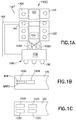
- the one or more load locks 102 A, 102 B may be arranged in a common horizontal plane in a side by side arrangement as can be seen in FIG. 1B .
- the one or more load locks may be arranged in a grid format such that at least two load locks 102 A, 102 B, 102 C, 102 D are arranged in rows (e.g. having spaced apart horizontal planes) and columns (e.g. having spaced apart vertical planes).
- the one or more load lock may be a single in-line load lock 102 A, 102 B as shown in FIGS. 1D and 1E .
- the at least one load lock 102 A, 102 B, 102 C, 102 D may be arranged in a stacked in-line arrangement as shown in FIGS. 1F and 1G . It should be understood that while load locks are illustrated on two lateral sides 100 S 1 , 100 S 2 of a transport chamber 125 in other aspects the one or more load lock may be arranged on a single lateral side or on one or more ends 100 E 1 , 100 E 2 of the transport chamber 125 . Each of the at least one load lock may also include one or more wafer/substrate resting planes WRP in which substrates are held on suitable supports within the respective load lock. In other aspects, the tool station may have any suitable configuration.
- each of the front end 101 , the at least one load lock 102 A, 102 B and back end 103 may be connected to a controller 110 which may be part of any suitable control architecture such as, for example, a clustered architecture control.
- the control system may be a closed loop controller having a master controller, cluster controllers and autonomous remote controllers such as those disclosed in U.S. Pat. No. 7,904,182 entitled “Scalable Motion Control System” issued on Mar. 8, 2011 the disclosure of which is incorporated herein by reference in its entirety. In other aspects, any suitable controller and/or control system may be utilized.
- the front end 101 generally includes load port modules 105 and a mini-environment 106 such as for example an equipment front end module (EFEM).
- the load port modules 105 may be box opener/loader to tool standard (BOLTS) interfaces that conform to SEMI standards E15.1, E47.1, E62, E19.5 or E1.9 for 300 mm load ports, front opening or bottom opening boxes/pods and cassettes.
- the load port modules may be configured as 200 mm wafer/substrate interfaces, 450 mm wafer/substrate interfaces or any other suitable substrate interfaces such as for example larger or smaller semiconductor wafers/substrates, flat panels for flat panel displays, solar panels, reticles or any other suitable object.
- the load port modules 105 may be configured to receive substrate carriers or cassettes C from an overhead transport system, automatic guided vehicles, person guided vehicles, rail guided vehicles or from any other suitable transport method.
- the load port modules 105 may interface with the mini-environment 106 through load ports 107 .
- the load ports 107 may allow the passage of substrates between the substrate cassettes and the mini-environment 106 .
- the mini-environment 106 generally includes any suitable transfer robot 108 which may incorporate one or more aspects of the disclosed embodiment described herein.
- the robot 108 may be a track mounted robot such as that described in, for example, U.S. Pat. No.
- the robot 108 may be substantially similar to that described herein with respect to the back end 103 .
- the mini-environment 106 may provide a controlled, clean zone for substrate transfer between multiple load port modules.
- the at least one vacuum load lock 102 A, 102 B may be located between and connected to the mini-environment 106 and the back end 103 .
- the load ports 105 may be coupled substantially directly to the at least one load lock 102 A, 102 B or the transport chamber 125 (see FIGS. 1H and 1I ) where the substrate carrier C is pumped down to a vacuum of the processing chamber 125 and substrates are transferred directly between the substrate carrier C and the load lock or processing chamber.
- the substrate carrier C may function as a load lock such that a processing vacuum of the transport chamber extends into the substrate carrier C.
- any suitable transfer apparatus may be provided within the load lock for transferring substrate to and from the substrate carrier C.
- vacuum as used herein may denote a high vacuum such as 10 ⁇ 5 Torr or below in which the substrates are processed.
- the at least one load lock 102 A, 102 B generally includes atmospheric and vacuum slot valves.
- the slot valves of the load locks 102 A, 102 B (as well as for the processing stations 130 ) may provide the environmental isolation employed to evacuate the load lock after loading a substrate from the atmospheric front end and to maintain the vacuum in the transport chamber when venting the lock with an inert gas such as nitrogen.
- the slot valves of the processing apparatus 100 may be located in the same plane, different vertically stacked planes or a combination of slot valves located in the same plane and slot valves located in different vertically stacked planes to accommodate transfer of substrates to and from at least the processing stations 130 and load locks 102 A, 102 B coupled to the transport chamber 125 .
- the at least one load lock 102 A, 102 B may also include an aligner for aligning a fiducial of the substrate to a desired position for processing or any other suitable substrate metrology equipment.
- the vacuum load lock may be located in any suitable location of the processing apparatus and have any suitable configuration.
- the vacuum back end 103 generally includes a transport chamber 125 , one or more processing station(s) 130 S, 130 T (generally referred to herein as processing station(s) 130 ) and any suitable transfer unit module or transport module 104 that includes one or more transfer robot 104 A, 104 B which may include one or more aspects of the disclosed embodiments described herein.
- the transport chamber 125 may have any suitable length L such as a length that complies with SEMI standard E72 guidelines. While two transfer robots 104 A, 104 B having at least one transfer arm are illustrated in FIG. 1 it should be understood that more or less than two transfer robots having any suitable number of transfer arms may be located within the transport chamber 125 .
- the transfer unit module 104 and the one or more transfer robot 104 A, 104 B will be described below and may be located within the transport chamber 125 to transport substrates between the load lock 102 A, 102 B (or between a cassette located at a load port) and the various processing stations 130 .
- the transfer unit module 104 may be removable from the transport chamber 125 as modular unit such that the transfer unit module 104 complies with SEMI standard E72 guidelines.
- the processing stations 130 may operate on the substrates through various deposition, etching, or other types of processes to form electrical circuitry or other desired structure on the substrates.
- Typical processes include but are not limited to thin film processes that use a vacuum such as plasma etch or other etching processes, chemical vapor deposition (CVD), plasma vapor deposition (PVD), implantation such as ion implantation, metrology, rapid thermal processing (RTP), dry strip atomic layer deposition (ALD), oxidation/diffusion, forming of nitrides, vacuum lithography, epitaxy (EPI), wire bonder and evaporation or other thin film processes that use vacuum pressures.
- the processing stations 130 are communicably connected to the transport chamber 125 in any suitable manner, such as through slot valves SV, to allow substrates to be passed from the transport chamber 125 to the processing stations 130 and vice versa.
- the slot valves SV of the transport chamber 125 may be arranged to allow for the connection of twin process stations 130 T (e.g. more than one substrate processing chamber located within a common housing), single process stations 130 S and/or stacked process modules/load locks (as will be described below).
- twin process stations 130 T e.g. more than one substrate processing chamber located within a common housing
- single process stations 130 S e.g. more than one substrate processing chamber located within a common housing
- stacked process modules/load locks as will be described below.
- the back end 103 may also include one or more slot valves SV to allow for the connection of a load lock 140 for transferring substrates from or to the transport chamber 125 .
- the inclusion of the load lock 140 in the back end 103 allows for substrates to enter the processing apparatus 100 through the front end 101 and exit the processing apparatus 100 through the back end.
- the load lock 140 may allow substrates to enter the processing apparatus through the back end 103 and exit through the front end 101 .
- substrates may enter and exit the processing apparatus from either or both of the front end or/and the back end (or at any point between ends of the transport chamber 125 as will be described below).
- FIG. 2 a processing apparatus 100 ′, substantially similar to processing apparatus 100 (e.g. except where noted) is illustrated.
- multiple transport chambers 125 A, 125 B may be coupled to each other to form the processing apparatus 100 ′ which has any suitable combined/assembled length such that each transport chamber module forming the processing apparatus 100 ′ has a length L (see FIG. 1 ) that complies with SEMI standard E72 guidelines.
- the transport chambers 125 A, 125 B are coupled to each other through at least one load lock 202 A, 202 B to allow module to module substrate handoff.
- each transport chamber 125 A, 125 B may allow each transport chamber 125 A, 125 B to have an internal environment that is different than the other transport chamber(s) 125 A, 125 B.
- the transport chambers 125 A, 125 B may have substantially the same internal atmosphere.
- each transport chamber includes load locks 102 A- 102 D for transferring substrates to and from the processing apparatus 100 ′ so that substrate may enter/exit the processing apparatus 100 ′ through either end 100 E 1 , 100 E 2 of the processing apparatus 100 ′.
- any suitable load lock (such as load locks 202 A, 202 B, 140 ) may be located between the ends 100 E 1 , 100 E 2 (see also FIGS.
- a substrate transport tunnel 183 (e.g. return tunnel) that is separate and distinct from the transport chamber 125 may communicably couple the mid-entry/exit point to, for example, a front end 101 or other suitable substrate loading station of the processing apparatus.
- the substrate transport tunnel 183 may provide substantially uninterrupted substrate passage between, for example, the mid entry/exit station and the front end or other suitable substrate holding station.
- the substrate transport tunnel 183 may be located in substantially the same horizontal plane as the transport chamber 125 while in other aspects the substrate transport tunnel 183 may be located in a plane that is vertically spaced from (e.g.
- the mid-entry/exit modules and substrate transport tunnels may be substantially similar to those described in U.S. Pat. No. 7,959,403 issued Jun. 14, 2011 the disclosure of which is incorporated herein by reference in its entirety.
- FIG. 2A another processing apparatus 100 ′′′ is illustrated in accordance with aspects of the disclosed embodiment.
- the transport chambers 125 A, 125 B may be communicably coupled so that a transfer unit module 104 of one transport chamber 125 A may substantially directly handoff substrates to a transfer unit module 104 of another transport chamber 125 B such as through a slot valve or other suitable opening connecting the transport chambers 125 A, 125 B.
- each transport chamber 125 A, 125 B are coupled to each other substantially directly through any suitable opening or slot valve SV but in other aspects any suitable load lock or other substrate holding station may be located between the transport chambers 125 A, 125 B.
- each transport chamber 125 may have an internal environment different from other transport chambers or one or more transport chambers may share an internal environment.
- FIGS. 3A and 3B a processing apparatus 100 ′′ substantially similar to processing apparatus 100 (e.g. except where noted) is illustrated in accordance with another aspect of the disclosed embodiment.
- the load locks 140 (or load ports for connecting substrate carriers substantially directly to the transport chamber) are located only on the lateral sides 100 S 1 , 100 S 2 of the transport chamber 125 .
- the load locks 140 (or load ports) may be located on the ends 100 E 1 , 100 E 2 and/or the lateral sides 100 S 1 , 100 S 2 as described above with respect to FIG. 1 .
- the process flow through the processing apparatus 100 , 100 ′, 100 ′′ described herein may be any suitable process flow such as, for example, illustrated in FIGS. 3A, and 3B .
- substrates may enter the transport chamber 125 through one of the load locks 140 A, 140 B.
- one load lock 140 A, 140 B may be an entry load lock and the other load lock 140 A, 140 B may be an exit load lock so that substrates enter the processing apparatus through one load lock and exit through the other load lock.
- the load locks 140 A, 140 B may be both entry and exit load locks so that substrates can enter or exit either load lock. As can be seen in FIGS.
- the transfer unit module 104 described herein may be configured to substantially simultaneously transfer substrates to opposing processing stations 130 (e.g. on either side 100 S 1 , 100 S 2 of the transport chamber 125 ) for processing and/or substantially simultaneously transfer substrates to side by side processing stations 130 (e.g. located on the same side 100 S 1 , 100 S 2 of the transport chamber 125 ) and/or provide a fast swapping of substrates at a single processing station (e.g. pick a substrate from the processing station and place another substrate to the processing station in rapid succession while a base of the transport robot remains substantially stationary).
- a single processing station e.g. pick a substrate from the processing station and place another substrate to the processing station in rapid succession while a base of the transport robot remains substantially stationary.
- the substrates may be processed through one or more processing stations 130 in any suitable order such that the substrate can be swapped at any suitable processing station 130 .
- the substrates may be processed in any suitable order that may be defined by a location of the entry and/or exit load lock 140 A, 140 B.
- the transfer unit module 104 may include a telescoping linear traversing mechanism or carriage 400 having a carriage frame 400 F to which the components of the telescoping linear traversing mechanism 400 are mounted.
- the telescoping linear traversing mechanism 400 may be a modular unit that allows the linear traversal aspect of the transfer unit module 104 to contract into a smaller package during installation, so as to comply with SEMI standard E72 guidelines as noted above, and provide any desired travel that allows the transfer arm(s) 450 , 451 or robot(s) of the transfer unit module 104 to access each process station 130 and load lock/load port coupled to the transport chamber 125 .
- the telescoping linear traversing mechanism 400 may include any suitable drive section which may include a Z-axis lift drive and one or more extension/retraction drives.
- the drive section of the telescoping linear traversing mechanism 400 may be substantially uncoupled from or not closely coupled to a drive section of the transfer arms (described below) carried by the telescoping linear traversing mechanism 400 which may allow for substantially independent kinematic operation of the telescoping linear traversing mechanism 400 and the transfer arm drives.
- the telescoping linear traversing mechanism 400 may be mounted to a lift (e.g.
- Z-axis lift drive 401 may move the telescoping linear traversing mechanism 400 (and the robot arms mounted thereto) as a unit in the direction of arrow 499 to any suitable desired height for allowing substrate transfer through the slot valves SV of the transport chamber 125 .
- the Z-axis lift drive 401 may be located in a fixed position (e.g. the drive may not move in X and y directions—see FIG. 1 ) at least partly within the transport chamber 125 (in other aspects the Z-axis drive may not be located within the transport chamber and or be movable in one or more of the X and Y directions).
- the Z-axis lift drive 401 may be any suitable drive including, but not limited to, ball-screw lift drives, scissor lift drives, hydraulic actuators, pneumatic actuators and magnetic actuators. As may be realized any suitable seal may be provided to isolate the Z-axis lift drive 401 from an internal environment of the transport chamber 125 .
- the transfer unit module 104 may not have any Z-axis movement capability.
- each transfer arm, or at least one of either transfer arm, of the transfer unit module 104 may have a respective Z-axis drive 401 ′ for independently moving a respective robot arm in the direction of arrow 499 independent of Z-axis movement of other transfer arms of the transfer unit module 104 .
- This independent and dedicated Z-axis drive(s) 401 ′ for at least one or for each transfer arm 450 , 451 may be provided in combination with the collective Z-axis drive 401 (or the collective Z-axis drive may not be provided).
- the telescoping linear traversing mechanism 400 may be centrally mounted within the transport chamber 125 such as along a transport chamber centerline CL ( FIG. 1 ) and be configured for bi-directional extension (e.g. capable of extension on either side of the transport chamber centerline CL) in the direction of arrow 199 for allowing the transfer arms of the transfer unit module 104 to access the processing stations 130 and load ports/load locks.
- the telescoping linear traversing mechanism 400 may be mounted adjacent an end 100 E 1 , 100 E 2 of the transport chamber 125 for extension along any suitable length of the transport chamber and for allowing transfer arm access to the processing stations 130 and load ports/load locks.
- the telescoping linear traversing mechanism 400 may be mounted at any suitable location of the transport chamber 125 .
- the telescoping linear traversing mechanism 400 (which may otherwise be referred to as a telescoping carriage mechanism) may include a base member 410 and at least one telescoping member or carriage 420 , 430 movably mounted to the base member 410 in series.
- the base may be fixedly connected to a wall of the transport chamber 125 at any suitable location, such through the Z-axis lift drive 401 .
- the base member 410 may be mounted to the Z-axis lift drive 401 in any suitable manner so as to be at least partly located within the internal environment of the transport chamber 125 .
- the base member 410 may include any suitable slide mechanism 410 T, such as rails or tracks, for movably mounting at least one telescoping member 420 , 430 to the base member 410 .
- telescoping member 420 includes any slide mechanism 420 T 1 that interfaces with slide mechanism 410 T so as to movably mount telescoping member 420 to the base member 410 .
- the interface between the slide mechanisms 410 T, 420 T 1 may be configured to allow reciprocating movement of the telescoping member 420 in the direction of arrow 199 on either side of base member centerline CL 1 relative to the base member 410 .
- the Z-axis drive unit is shown as being substantially located on the centerline CL in other aspects the Z-axis drive unit 401 may be offset from the centerline. It should also be understood that a centerline CL 1 of the base member 410 may be substantially coincident or offset from the centerline CL.
- the telescoping member 420 may also include slide mechanism 420 T 2 (which may be substantially similar to slide mechanism 410 T) for movably mounting telescoping member or robot support 430 to the telescoping member 420 .
- Telescoping member 430 may be a robot support on which one or more transfer arms 450 , 451 are located.
- the telescoping member 430 may include slide mechanism 430 T configured to interface with slide mechanism 420 T 2 and such that the interface is configured to allow reciprocating movement of the telescoping member 430 in the direction of arrow 199 on either side of telescoping member centerline CL 2 relative to the telescoping member 420 .
- Each of the base member 410 and telescoping members 420 , 430 may have any suitable respective length L 2 , L 3 , L 4 to allow traversal of the transfer arm(s) of the transfer unit module 104 between the ends 100 E 1 , 100 E 2 of the transport chamber 125 .
- telescoping linear traversing mechanism 400 is illustrated as having three members 410 , 420 , 430 in other aspects the telescoping linear traversing mechanism may have more or fewer members for providing a telescoping platform or robot support on which one or more transfer arms (and their respective drives) are mounted.
- each of the telescoping members may be uncoupled from movement of other ones of the telescoping members (and/or transfer arms) so that each telescoping member (and/or transfer arm) is independently reciprocally driven in the direction of arrow 199 by any suitable drive 470 in any suitable manner.
- the drive 470 may include one or more drive motors 471 , 471 ′, 471 ′′, 471 ′′′ for independently driving (independent movement of one or more of the transfer arms will be described in greater detail below with respect to FIGS.
- Each drive motor 471 , 471 ′, 471 ′′, 471 ′′′ may be coupled to its respective telescoping member 410 , 420 , 430 in any suitable manner such as that described below with respect to the drive motor 471 for telescoping member 420 .
- the drive motor 471 may be fixedly mounted to any suitable portion of base member 410 (or the telescoping member from which the driven telescoping member depends) for driving the driven telescoping member, which in this example, is telescoping member 420 .
- the drive motor 471 may be mounted to the driven telescoping member and the drive member 474 (described below) may be anchored to the base member 410 (or the telescoping member from which the driven telescoping member depends).
- the drive motor 471 may be any suitable drive motor (e.g.
- linear brushless motor linear stepper motor, linear variable reluctance motor, etc.
- suitable for use within a vacuum environment such as may be found within the transport chamber 125 .
- the motors may have a rotary configuration and suitable transmission.
- Any suitable drive pulley 472 may be mounted to an output of the drive motor 471 .
- Idler pulleys 473 A, 473 B may be mounted to or adjacent ends 420 E 1 , 420 E 2 (or mounted at any other suitable location) of telescoping member 420 .
- One or more suitable drive member 474 (such as e.g.
- cord, cable, band, wire, chain, belt, etc. may span between and interface with pulleys 473 A, 473 B such that the ends (or other suitable portion of the drive member 474 ) are wrapped around the drive pulley 472 in a counter-rotating manner so that as one end is wound around the drive pulley the other end is unwound from the drive pulley.
- a portion of the drive member 474 that spans between the pulleys 473 A, 473 B may be fixed to any suitable portion of the telescoping member 420 in any suitable manner, such as with any suitable mechanical or chemical fasteners 475 . It is noted that while a single drive member 474 is illustrated in other aspects more than one drive member may be used in a similar configuration as that described herein.
- a similar drive arrangement may be provided between telescoping members 420 , 430 for allowing movement of telescoping member 430 relative to telescoping member 420 such that a drive motor 471 is mounted to any suitable portion of the telescoping member 420 and pulleys 473 A, 473 B are mounted to any suitable portion of telescoping member 430 .
- the drive member 474 may be fixed to the telescoping member 430 in a manner similar to that described above such that as the drive pulley 472 rotates the telescoping member is reciprocated in the direction of arrow 199 depending on the direction of drive pulley rotation.
- extension and retraction of the telescoping linear traversing mechanism 400 is described as being performed with motors distributed on the base member and telescoping members, in other aspects the motors for extending and retracting the telescoping linear traversing mechanism 400 may be located at a common location such that suitable drive mechanisms/linkages couple the respective motors to a respective driven member of the telescoping linear traversing mechanism 400 for allowing extension and retraction of the telescoping linear traversing mechanism 400 .
- the movement of telescoping members 410 , 420 , 430 in the direction of arrow 199 may be linked together in any suitable manner such that one drive motor effects the telescopic extension/retraction of the telescoping members 410 , 420 , 430 in the direction of arrow 199 to either side of the centerline CL.
- any suitable pulley and drive member arrangement may couple the motion of one telescoping member to one or more of the other telescoping members for extending the telescoping linear traversing mechanism 400 .
- the transfer unit module 104 may include a telescoping linear traversing mechanism 400 that may substantially span from adjacent one lateral side 100 S 1 , 100 S 2 of the transport chamber to adjacent the other lateral side 100 S 1 , 100 S 2 of the transport chamber (e.g. the telescoping linear traversing mechanism 400 spans a width W of the transport chamber).
- the transfer unit module 104 may include more than one transfer unit module 104 ′, 104 ′′ each having a respective telescoping linear traversing mechanism 400 A, 400 B located laterally side by side within the transport chamber 125 where the transport arm(s) 450 , 451 ( FIG.
- each transfer unit module 104 ′, 104 ′′ has a reach such that each arm is capable of transferring substrates through slot valves SV located on either lateral side 100 S 1 , 100 S 2 of the (e.g. for accessing processing stations, load locks and/or load ports communicably connected thereto) as well as accessing substrate holding stations located on the ends 100 E 1 , 100 E 2 of the transport chamber 125 .
- the side by side telescoping linear traversing mechanisms 400 A, 400 B allow substantially independent travel of a respective robot support 430 ( FIG. 7 ) in the direction of arrow 199 along a length of the transport chamber 125 (e.g.
- the linear traversing mechanism 400 may be mounted to a linear track 493 in a manner similar to that described in U.S. Pat. Nos. 8,419,341, 6,002,840 and 7,648,327, previously incorporated by reference.
- the linear track 493 may include any suitable drive configured to move the linear traversing mechanism 400 along the length of the track.
- each of the telescoping linear traversing mechanisms 400 A, 400 B may have a respective Z-axis motor allowing substantially independent Z-axis movement of each telescoping linear traversing mechanisms 400 A, 400 B while in other aspects the telescoping linear traversing mechanisms 400 A, 400 B may be mounted to a common Z-axis drive such that the telescoping linear traversing mechanisms 400 A, 400 B are raised and lowered as a unit.
- the linear traversing mechanism 400 may be mounted on a Z-axis platform or drive in any suitable manner.
- a Z-axis track 493 Z, 493 Z′ may be mounted to the linear track 493 for movement along the linear track 493 .
- the Z-axis track 493 Z, 493 Z′ may include any suitable drive for driving a carriage 493 C, 493 C′ along the Z-axis track 493 Z where the linear traversing mechanism is mounted to the carriage 493 C, 493 C′ in any suitable manner.
- the Z-axis track may be configured for telescopic movement and include a telescopic drive mechanism 493 ZD ( FIG. 4J ) that may be substantially similar to that described above with respect to FIGS. 4B and 4C .
- the telescoping linear traversing mechanism 400 A, 400 B may include more than one telescoping mechanism such that one telescoping mechanism depends from another telescoping member.
- a telescoping Z-axis track (as noted above) may be mounted to carriage 430 or the telescoping arm (such as that illustrated in FIG. 4B ) may be mounted to the carriage 493 C, 493 C′ of a telescoping Z-axis track.
- robot drives 501 , 502 (which will be described below) may be placed laterally side by side on a common robot support 430 where each robot drive 501 , 502 is configured to drive one or more robot arms mounted thereto.
- the laterally side by side robot drives 501 , 502 may be fixed relative to one another on the robot support 430 while in other aspects one or more of the laterally side by side robot drives 501 , 502 may be movable in the direction of arrow 199 relative to another one of the laterally side by side robot drive 501 , 502 in a manner substantially similar to that described herein with respect to FIG. 7 and slide member 700 .
- each of the drives 501 , 502 may include a respective Z-axis drive configured to allow substantially independent Z-axis movement of one or more robot arm mounted thereto while in other aspects the drives 501 , 502 may be mounted to a common Z-axis drive such that the drives 501 , 502 are raised and lowered as a unit.
- the more than one telescoping linear traversing mechanism 400 may be arranged in a vertically opposing arrangement such that the transfer robots 104 of the more than one telescoping linear traversing mechanism 400 are vertically opposed to one another.
- a telescoping travel path of the transfer unit module 104 may cross an axis of entry/exit through a slot valve or other transport chamber opening through which a substrate holding station is communicably coupled to the transport chamber 125 .
- Positioning of the telescoping member for locating the transfer arms 450 , 451 within the transport chamber 125 may be performed in any suitable manner. In one aspect positioning of the telescoping member(s) may be performed with any suitable sensor/sensor arrangement. As may be realized, at least the position of the robot support (in this aspect telescoping member 430 ), on which the transfer arms 450 , 451 are located, is tracked in any suitable manner for locating the transfer arms 450 , 451 . In one aspect tracking the position of the telescoping member 430 may be performed using encoders of the drive motors 471 as each telescoping member 420 , 430 is extended/retracted. In another aspect (referring to FIG.
- one or more sensors 280 S may be placed along or at predetermined locations on one or more walls within the transport chamber 125 .
- the sensors 280 S may be any suitable sensors such as, for example, laser or beam sensors, capacitive sensors and/or inductive sensors.
- the sensors 280 S may be located within the transport chamber such that each sensor 280 S has a predetermined relationship with respect to one or more slot valves (and the processing stations communicably coupled to the slot valves).
- the sensors 280 S may be configured to detect or otherwise sense one or more targets 280 T located on the robot support (e.g. in this aspect telescoping member 430 ) where the targets 280 T have a predetermined spatial relationship with respect to the one or more transfer arm 450 , 451 .
- the sensors 280 S may send any suitable signals to any suitable controller, such as controller 110 , when the sensors 280 S detect targets 280 T.
- the signals may identify the location of the robot support 430 and, via the spatial relationship between the targets 280 T and the one or more transfer arm 450 , 451 , the location of the one or more transfer arm 450 , 451 .
- positioning of the telescoping member 430 may be performed mechanically with any suitable robot support locating features such as for example, pins, recesses, protrusions or any other suitable kinematic coupling configured to establish alignment (in the X, Y and Z planes) between telescoping member 430 and a predetermined processing station 130 and/or load lock/load port 140 , 105 .
- a locating feature 281 S may be mounted at any suitable location within transport chamber 125 such that a predetermined positional relationship is known between the locating feature 281 S and a corresponding processing station 130 and/or load lock/load port 140 , 105 .
- a mating feature 281 T (configured to kinematically mate with the locating feature) may be mounted to a predetermined location of the telescoping member 430 so as to have a predetermined relationship with the one or more transfer arm 450 , 451 mounted on the telescoping member 430 .
- the mating feature 281 T may engage and mate with a locating feature 281 S so as to locate the telescoping member 430 within the transport chamber 125 at a known position.
- the locating features 281 T may be retractable to allow the telescoping members 420 , 430 to pass by the locating features 281 T such that the controller 110 may effect deployment of the locating features 281 T corresponding to one or more predetermined substrate holding stations (e.g. 105 , 130 , 140 ) to/from which substrates are to be picked or placed as the telescoping member 430 advances towards the one or more predetermined substrate holding stations.
- the robot support may be movable in, for example, the Y directions (e.g. transverse to arrow 199 ) in any suitable manner for engaging a stationary (e.g. non-retractable) locating feature 281 T located adjacent a lateral side of the transport chamber 125 .
- the robot support (e.g. telescoping member 430 ) positioning may be substantially independent of the kinematics for transfer arm positioning (e.g. for picking and placing substrates to substrate holding stations).
- the location of the transfer arm end effector e.g. for holding the substrate
- Positioning of the telescoping member substantially independent of the kinematics associated with the extension and retraction of the transfer arm may also allow automatic substrate centering.
- one or more substrate centering sensors AWCS may be located at any suitable position(s) within and/or adjacent to the transport chamber 125 .
- one or more substrate centering sensors AWCS may be positioned on telescoping member 430 . As the transfer arm(s) extend past these sensors AWCS the sensors may detect a substrate held on the transfer arm and send signals corresponding to a position of the substrate to any suitable controller so that a position of the substrate may be automatically adjusted (e.g. automatic wafer centering) by the transfer arm for placing the substrate in a manner substantially similar to that described in one or more of, for example, U.S. provisional patent application No.
- At least one transfer robot 104 A, 104 B is located on a respective robot support (e.g. which in the examples illustrated herein is telescoping member 430 ) and is configured so that at least one transfer arm of the at least one transfer robot is rotatable relative to the carriage and robot support.
- two or more transfer robots 104 A, 104 B may be located on a common mobile base or robot support as illustrated in the Figs. It is noted that to allow access to side by side parallel processing stations (e.g. such as processing stations 130 T, 130 in FIG. 1 —see also FIGS. 2 and 3A-3B ) and/or interaction with end positioned wafer entry load locks (e.g.
- one or more robot drives 501 , 502 may be placed on the telescoping member 430 (e.g. each transfer arm 450 , 451 has a respective robot drive— FIG. 7 ).
- the robot drives 501 , 502 may be configured to couple with any suitable transfer arm 450 , 451 design configured for operation with a single drive spindle, coaxial drive spindle (e.g. two coaxially arranged drive shafts), tri-axial drive spindle (e.g. three coaxially arranged drive shafts) or any other suitable number of spindles (e.g. one or more drive shafts) arranged coaxially, side by side or a combination thereof.
- any arm linkage mechanism of which can be coupled with a series of spindle shafts in a coaxially configured manner capable of handling one or more substrates simultaneously or incrementally can be applied to this mechanism.
- Suitable examples of arm linkage mechanisms can be found in, for example, U.S. Pat. No. 7,578,649 issued Aug. 25, 2009, U.S. Pat. No. 5,794,487 issued Aug. 18, 1998, U.S. Pat. No. 7,946,800 issued May 24, 2011, U.S. Pat. No. 6,485,250 issued Nov. 26, 2002, U.S. Pat. No. 7,891,935 issued Feb. 22, 2011, U.S. Pat. No. 8,419,341 issued Apr. 16, 2013 and U.S. patent application Ser. No.
- the transfer arms 450 , 451 may be derived from a conventional SCARA (selective compliant articulated robot arm) type design, which includes an upper arm, a band-driven forearm and a band-constrained end-effector, or from a telescoping arm or any other suitable arm design. Suitable examples of transfer arms can be found in, for example, U.S. patent application Ser. No.
- the transfer arm 450 , 451 is described herein as having a general SCARA arm configuration having an upper arm UA, a forearm FA and an end effector or substrate holder EE (see FIG. 7 ).
- the SCARA arm(s) may have one link, two links, or more than three links and may have any suitable drive pulley arrangement such as a 2:1 shoulder pulley to elbow pulley arrangement and a 1:2 elbow pulley to wrist pulley arrangement.
- the transport arms may have any other desired arrangement such as a frog-leg arm 195 ( FIG. 1J ) configuration, a leap frog arm 193 ( FIG. 1L ) configuration, a bi-symmetric arm 194 ( FIG.
- one robot drive 501 , 502 may be positioned on the telescoping member 430 at a higher elevation than the other drive 501 , 502 as can be seen in FIG. 4A (e.g. may be located a predetermined height H 1 above the other drive(s)) which also places the transfer arms 450 , 451 (and their respective end effectors) at different elevations. Placing the robot drives 501 , 502 (and their respective arms 450 , 451 ) at different elevations may enable the transfer arms 450 , 451 to access, for example, load locks 102 A, 102 B positioned at an end 100 E 1 , 100 E 2 of the transport chamber 125 as shown in FIG. 5 .
- the robot drives 501 , 502 may be arranged longitudinally one behind the other along a longitudinal center line CLC of the telescoping member 430 .
- the drives 501 , 502 (and their respective transfer arms 450 , 451 ) may be located at the same height (so that the substrates carried by the arms are transferred in substantially the same plane).
- the motion of the transfer arms 450 , 451 may be controlled by, for example, controller 110 to allow one transport arm 450 , 451 to pass by the other transfer arm 450 , 451 to allow each arm to pick and place substrates from and to a common or different substrate holding locations (e.g.
- one transfer arm such as transfer arm 450
- arm 451 may be similarly moved to allow arm 450 access to a substrate holding location.
- the transfer arms 450 , 451 may be controlled by, for example, controller 110 so that one transfer arm transfers substrates at an end 100 E 1 of the transport chamber 125 while the other transfer arm transfers substrates at the other end 100 E 2 of the transport chamber 125 .
- transport arm 450 may not be capable of extending into load locks 102 A, 102 B.
- the controller 110 may be suitably programmed such that any substrate that is to be placed in the load locks 102 A, 102 B is removed from a substrate holding station (such as processing stations 130 S, 130 T) by transfer arm 451 (e.g. the transfer arm closest to the end 100 E 1 .
- transfer arm 451 e.g. the transfer arm closest to the end 100 E 1 .
- placement of substrates in substrate holding stations located at end 100 E 2 of the transport chamber 125 may be removed from the processing stations by transfer arm 450 (e.g. the transfer arm closest to end 100 E 2 ).
- each robot drive 501 , 502 may be fixedly mounted to the telescoping member 430 so as to be longitudinally and laterally (e.g. in the X and Y directions) stationary or fixed relative to the telescoping member 430 as illustrated in FIG. 6 .
- the spacing SPR between the robot drives 501 , 502 (a rotation axis of which may be coincident with an axis of extension and retraction of the respective transfer arm 450 , 451 ) may be substantially the same as a spacing SPHS between the processing stations 130 , load ports 105 and/or load locks 140 .
- the transfer arms 450 , 451 are to access load locks 102 A, 102 B (or similarly arranged load ports) located at an end of the transport chamber 125 as shown in FIGS. 1 and 5 it is noted that the length or reach of one of the arms 450 may be greater than the length or reach of the other arm 451 to allow the arm 450 to reach around arm 451 for accessing the load locks 102 A, 102 B (or similarly arranged load ports).
- the lengths of the arms may be accomplished by increasing the length of one or more arm links UA, FA, EE such that, in one aspect, the arm links all have a substantially similar length, while in other aspects the arm links have unequal lengths.
- the length or reach of the transfer arms 450 , 451 may be substantially similar where at least one of the robot drives 501 , 502 is movable relative to the other one of the robot drives 501 , 502 and to the telescoping member 430 .
- the lengths of the transfer arms 450 , 451 may be different where at least one of the robot drives 501 , 502 is movable relative to the other one of the robot drives 501 , 502 and to telescoping member 430 . Referring now to FIGS. 7 and 7B one of the robot drives, in this example robot drive 502 , is fixedly mounted to the telescoping member 430 .
- the telescoping member 430 may include a slide member 700 movably mounted to the telescoping member 430 in any suitable manner where the slide member is driven by drive motor 471 ′′ ( FIG. 4K ) so as to move in direction 199 (e.g. longitudinally along a length of the transport chamber 125 ) relative to the telescoping member 430 .
- the slide member 700 may also be configured to move transversely to direction 199 .
- the movable coupling between the slide member 700 and the telescoping member 430 may be substantially similar to that described above with respect to the telescoping members 430 , 420 and base member 410 .
- the other robot drive 501 may be fixedly mounted to the slide member 700 so that as the slide member 700 moves robot drive 501 moves relative to the robot drive 502 changing the spacing SPR ( FIG. 6 ) between the drives.
- both of the robot drives 501 , 502 (and hence the corresponding transfer arms 450 , 451 depending therefrom) may be independently movable (e.g. in the direction of arrow 199 A, 199 B) relative to the telescoping member 430 and to each other.
- robot drive 502 may also be mounted to the telescoping member 430 by a slide member 700 ′, which may be substantially similar to slide member 700 described above.
- the slide member 700 ′ may be driven by drive motor 471 ′′′ so as to move in direction 199 (e.g. longitudinally along a length of the transport chamber 125 ) relative to the telescoping member 430 .
- direction 199 e.g. longitudinally along a length of the transport chamber 125
- the independent linear movement of each robot drive 501 , 502 relative to the telescoping member 430 and to each other enables changing the position relative to the telescoping system and the spacing between the drives 501 , 502 (and their respective transfer arms 450 , 451 ).
- the independent linear movement of each of the robot drives 501 , 502 also enables the traversal of each of the respective transfer arms 450 , 451 in the direction of arrow 199 at different transport rates.
- the drives 471 , 471 ′, 471 ′′, 471 ′′′ may drive their respective telescoping members/robot drives in the same direction (such as for maximum linear traverse along the chamber, which may be referred to as coincident motion) or in opposing directions (so that at least one telescoping member or carriage or arm/drive of the telescoping system is moved in an opposite linear direction from another telescoping member or carriage or arm/drive, which may be referred to as crossing or opposing motion).
- the drive 471 ′′ may move the robot drive 501 in the direction of arrow 199 A while one or more of drives 471 , 471 ′, 471 ′′′ move their respective telescoping member/robot drive in the direction of arrow 199 B so that transfer arm 450 remains substantially stationary in the direction of arrow 199 while the transfer arm 451 moves in the direction of arrow 199 B towards the transfer arm 450 or vice versa.
- changing the spacing SP 1 between the drives with one or more of the slide members 700 , 700 ′ allows the pivot or shoulder axes of the transfer arms 450 , 451 to move closer together allowing the length or reach of the transfer arms 450 , 451 to be substantially the same or otherwise decrease a difference in reach or length between the transfer arms when compared to the robot drives having the fixed spacing SPR described above with respect to FIG. 6 .
- changing the spacing SP 1 between the drives with one or more of the slide members 700 , 700 ′ allows the pivot or shoulder axes of the transfer arms 450 , 451 to move closer together so that the spacing SP 1 between the transfer arms may be adjusted to substantially match the spacing SP 2 between any adjacent process modules 130 T (see FIG. 1 ).
- Moving the shoulder axes of the transfer arm arms closer together may also allow the arms to access a common substrate station and allow for the fast swapping of substrates substantially without movement of the telescoping member 430 .
- the slide member 700 may be cantilevered from the telescoping member 430 as shown in FIG. 7A so that as the slide member 700 moves in direction 199 a length LX of the telescoping member 430 changes which may allow for accessing load locks 102 A, 102 B (or similarly arranged load ports 105 ) at either end 100 E 1 , 100 E 2 of the transport chamber 125 .
- the transfer arms 450 , 451 may be independently linearly movable relative to each other (in a manner generally similar to that described above).
- a base member 410 ′ is mounted to the drive 401 .
- One or more telescoping members or carriages 420 ′, 420 ′′ are movably coupled or mounted to base member 410 ′ (each carriage may be independent of the other).
- the transfer arms 450 , 451 are mounted to respective arm drive telescoping members or carriages 430 ′, 430 ′′ which are movably coupled or mounted to a respective telescoping member 420 ′, 420 ′′.
- the telescoping members 420 ′, 420 ′′, 430 ′, 430 ′′ may be driven by a direct drive motor such as for example, a linear motor.
- a direct drive motor such as for example, a linear motor.
- any suitable linear motors 480 , 480 ′ may be mounted to the base member 410 ′ for driving a respective telescoping member 420 ′, 420 ′′ (e.g. the windings of the motor may be disposed on the base member and a movable platen or driven member may disposed on the telescoping member or vice versa).
- Any suitable linear motors 481 , 481 ′ may be mounted to a respective telescoping member 420 ′, 420 ′′ for driving a respective telescoping member 430 ′, 430 ′′ (e.g. the windings of the motor may be disposed on the telescoping member 420 ′, 420 ′′ and a movable platen or driven member may disposed on the telescoping member 430 ′, 430 ′′ or vice versa).
- rotary motors such as those described above with respect to FIG.
- any suitable encoders 483 may be provided for sensing or otherwise tracking a position of a respective one of the telescoping members 420 ′, 420 ′′, 430 ′, 430 ′′.
- the telescoping member 430 ′, 430 ′′ may include any suitable number of drives 484 for driving the arm link(s) and end effector(s) of the respective transfer arms 450 , 451 .
- the independent linear movement of each of the transfer arms 450 , 451 and the telescoping members 420 ′, 420 ′′ relative to each other and the base member 410 ′ allows movement of the transfer arms 450 , 451 in the direction of arrow 199 relative to the secondary link member in any ratio of movement.
- the linear telescoping system may have two or more independent linear telescoping sections each with one or more resident arms, and each independent linear telescoping section having (but not limited to) two or more linear degrees of freedom in the direction of arrow 199 .
- the arms resident on each independent linear telescoping section may have at least two degrees of freedom (e.g.
- the transfer arms 450 , 451 may have a common Z axis movement drive while in other aspects one or more of the transfer arms 410 , 451 may be independently movable in the Z direction.
- the base member 410 ′ could remain static as the robot arm 450 , 451 (coupled to a respective telescoping member 420 ′, 420 ′′) moves along the respective telescoping member 420 ′, 420 ′′ to an extent of travel within the respective telescoping member 420 ′, 420 ′′. This may allow for movement of the transfer arms 450 , 451 in the direction of arrow 199 without moving the respective telescoping member 420 ′, 420 ′′.
- the robot drive may be employed in any suitable environment such as a vacuum environment of the transport chamber 125 .
- the robot drive 800 may be substantially similar to drives 501 , 502 described above and include a drive housing 800 H having at least one drive shaft 810 , 811 at least partially disposed therein.
- the robot drive housing 800 H may be a sealed housing configured so that the electrically powered components of the robot drive (e.g. the stator, sensors, etc.) are isolated or otherwise sealed from the environment within the transport chamber 125 .
- the stators 800 S 1 , 800 S 2 may be located in one or more sealed chambers 820 .
- the sealed chambers may be formed from at least any suitable housing members 820 H (which may form at least part of the housing 800 H) and a barrier or seal 830 .
- the housing members 820 H may be integrally formed with housing 800 H or the housing members 820 H may be coupled to a frame for form the housing 800 H.
- any suitable seals 820 S may be provided between housing members 820 H and/or housing 800 H to seal the electrically powered components of the robot drive from an external environment in which the drive operates.
- the barrier 830 may be located between the stators 800 S 1 , 800 S 2 and their respective rotors 800 R 1 , 800 R 2 so that the rotors operate within the external environment and are driven by the stators through the barrier 830 (which may be disposed between the moving parts of the robot drive and/or sensors and the corresponding stationary parts of the robot drive and/or sensors).
- the drive 800 is a two axis drive but in other aspects the drive may have any suitable number of axes.
- the drive shafts 810 , 811 may be mechanically suspended or magnetically suspended within the housing 800 H in any suitable manner.
- the drive shafts 810 , 811 are suspended within the housing by any suitable bearings 800 B but in other aspects the drive shaft may be magnetically suspended (e.g. a self-bearing drive) in a manner substantially similar to that described in U.S. Pat. No. 8,283,813 entitled “Robot Drive with Magnetic Spindle Bearings” issued on Oct. 9, 2012, the disclosure of which is incorporated by reference herein in its entirety.
- Each drive 810 , 811 shaft of the drive 800 may be driven by a respective motor 800 R 1 , 800 R 2 where each motor includes a stator 800 S 1 , 800 S 2 and a rotor 800 R 1 , 800 R 2 .
- the drive motors described herein may be permanent magnet motors, variable reluctance motors (having at least one salient pole with corresponding coil units and at least one respective rotor having at least one salient pole of magnetic permeable material), or any other suitable drive motors.
- the stator(s) 800 S 1 , 800 S 2 may be fixed within the housing as noted above and the rotor(s) 800 R 1 , 800 R 2 may be fixed in any suitable manner to a respective drive shaft 810 , 811 .
- the stators 800 S 1 , 800 S 2 may be located in an environment that is sealed from an atmosphere in which the robot arm(s) 450 , 451 operate (the atmosphere in which the robot arm(s) operate is referred to herein as a “sealed” environment which may be a vacuum or any other suitable environment) through the employment of the isolation wall or barrier 830 while the rotors 800 R 1 , 800 R 2 are located within the sealed environment in a manner substantially similar to that described in U.S. Pat. No. 5,720,590 issued on Feb. 24, 1998, U.S. Pat. No. 5,899,658 issued on May 4, 1999 and U.S. Pat. No. 5,813,823 issued on Sep. 29, 1998, the disclosures of which are incorporated by reference herein in their entireties.
- the motors 800 M 1 , 800 M 2 are shown in a stacked arrangement (e.g. in line and arranged one above or one in front of the other).
- the motors 800 M 1 , 800 M 2 may have any suitable arrangement such as a side by side or concentric arrangement as shown in FIG. 9 .
- the motors may be low profile planar or “pancake” style robot drive configuration where the motors are concentrically nested within each other in a manner substantially similar to that described in U.S. Pat. No. 8,008,884 entitled “Substrate Processing Apparatus with Motors Integral to Chamber Walls” issued on Aug. 30, 2011 and U.S. Pat. No. 8,283,813 entitled “Robot Drive with Magnetic Spindle Bearings” issued on Oct. 9, 2012, the disclosures of which are incorporated by reference herein in their entireties.
- the drives described herein may carry any suitable type of transfer arm (as noted above) configured to transport, for example, semiconductor wafers, flat panels for flat panel displays, solar panels, reticles or any other suitable payload. It is also noted that the drives described herein may also carry any suitable number of transfer arms. It is noted (as seen in FIG. 1 ) that each drive may have the same or a different number of transfer arms mounted thereto. For example, in one aspect, the drive illustrated in FIG. 8 may be configured to drive a single transfer arm (see for example transfer robot 104 A in FIG.
- each of the one or more drives, such as drive 900 D, mounted to the telescoping member 430 may be configured to independently drive (e.g. in extension and rotation) or jointly drive (e.g. one or more of the rotation and extension are coupled) two or more transfer arms 904 A, 904 B in a manner substantially similar to that described in U.S. Pat. No. 7,891,935 issued on Feb. 22, 2011, the disclosure of which is incorporated by reference herein in its entirety.
- the controller 110 may include any suitable interlocks (mechanical interlocks may also be employed) configured to rotate each arm so that operation of one arm does not interfere with operation of the other arm when picking and placing substrates to and from substrate holding stations located at the lateral sides and/or ends of the transport chamber 125 .
- the term “four-axis” refers to the system of revolute joint/link pairs that allow the motion of the limbs of the arms in a plane described by polar R- ⁇ coordinates. The mechanism of the vertical displacement of the arm is not included in the term “four-axis.”
- the number of degrees of freedom does not take into account the entire robot's manipulator, but rather only the transfer arms.
- the transfer arms are independently rotatable about the revolute joints T 1 and T 6 , wherein rotation of an individual transfer arms is a change in the ⁇ coordinate of the end effector mounting flange, the last link of the manipulator.
- the rotation occurs about the common axis 22 .
- the end effector mounting flanges E 1 , E 2 are independently extendible and retractable via the linkage defined by the inner links L 1 , L 3 , the outer links L 2 , L 4 (e.g. upper arms), and the rotary joints T 1 through T 6 along a centerline drawn along the end effector and projected toward the common axis 22 .
- Two actuator assemblies are provided for each arm to effect these extension/retraction and rotation motions.
- the four actuators are housed within any suitable housing (such as housing 800 H described above), mounted to the telescoping member 430 and connected via co-axially located shafts 34 , 44 , 54 , 64 to the transfer arms 904 A, 904 B.
- Two actuators are connected to the housings of the inner links L 1 and L 3 , while the other two actuators are connected to pulleys located in the joints T 1 and T 6 of the inner links L 1 and L 3 .
- the action of the linkages and the actuator assemblies in particular when embodied as motors M 1 , M 2 , M 3 , M 4 , is discussed further below.
- motion of the end effector mounting flanges E 1 , E 2 is produced by manipulation of the inner and outer links incorporating a series of belts and pulleys.
- the inner link L 1 is connected to the telescoping member 430 via the shoulder rotary joint T 1 .
- the outer link L 2 is connected to the inner link L 1 via the elbow rotary joint T 2 .
- the end effector mounting flange E 1 is connected to the outer link L 2 via the wrist rotary joint T 3 .
- the links and joints of this part of the manipulator form a kinematic chain that is open at one end and connected to the telescoping member 430 at the other.
- the end effector which is not a part of the schematic and is not shown, is connected to the end effector mounting flange E 1 .
- a pulley d 1 is provided at the shoulder rotary joint T 1
- a pulley d 2 is provided at the elbow rotary joint T 2
- a belt t 1 extending along the inner link L 1 is connected to the pulleys d 1 and d 2 .
- the pulley d 2 while physically located in the inner link L 1 , is mounted to the link L 2 and, as a part of the elbow rotary joint T 2 , allows rotation of the link L 2 about the joint axis of the preceding link L 1 .
- a pulley d 3 is also provided at the elbow joint T 2
- a pulley d 4 is provided at the wrist rotary joint T 3 .
- the pulley d 3 while located physically in the link L 2 , is attached to the link L 1 and is a part of the axis about which the elbow joint T 2 of the link L 2 revolves.
- the pulley d 4 while physically located within the link L 2 , is attached to the end effector mounting flange E 1 and, as a part of the wrist joint T 3 , allows the rotation of the end effector mounting flange E 1 about the joint axis of the preceding link L 2 .
- a belt t 2 is connected to the pulleys d 3 and d 4 .
- the pulley d 3 fixed to the link L 1 at the axis about which the elbow joint T 2 of the link L 2 rotates, travels with the housing of the link L 1 when the shoulder joint T 1 of the link L 1 is rotated about the common axis 22 .
- the pulley d 2 is also constrained to move with the link L 1 , which causes the pulley d 2 to move in a fashion similar to the movement of a satellite gear of a planetary gear box.
- the pulley d 2 rotates around the common axis 22 of the shoulder joint T 1 , because it is attached to the distal axis of the inner link L 1 via the elbow joint T 2 .
- the pulley d 2 also rotates about the distal axis of the preceding link L 1 .
- the rotation occurs as a result of the pulley d 2 being connected to the pulley d 1 via a belt t 1 , such as a timing belt, chain, or cable.
- the ratio between the diameters of the pulleys d 1 and d 2 effects the relative angular displacement of the pulley d 2 , depending on the amount of angular displacement given to the actuator input connected to the link L 1 (e.g., motor M 1 ) and the actuator input connected to the pulley d 1 (e.g., motor M 2 ).
- the R- ⁇ coordinates of the proximal end of the subsequent link L 2 attached to the elbow joint T 2 and the orientation of the link L 2 around the T 2 joint axis of rotation are defined.
- R- ⁇ coordinates of the distal end of the link L 2 which contains the axis of rotation of the wrist joint T 3 , depend on the length of the link L 2 .
- the position in the R- ⁇ coordinate system of the proximal end of the end effector mounting flange, link E 1 , attached to the wrist joint T 3 and the orientation of E 1 around the T 3 joint axis of rotation depends on the following conditions: the angular input value to the link L 1 (via motor M 1 ), the angular input value to the pulley d 2 (via motor M 2 ), the length of the link L 1 , the pulley diameter ratio d 1 /d 2 , the length of the link L 2 , and the pulley diameter ratio d 3 /d 4 .
- the other transfer arm 904 A is similar.
- the inner link L 3 is connected to the telescoping member 430 via the shoulder rotary joint T 6 .
- the outer link L 4 is connected to the inner link L 3 via the elbow rotary joint T 4 .
- the end effector mounting flange E 1 is connected to the outer link L 4 via the wrist rotary joint T 5 .
- the links and joints of this part of the manipulator form a kinematic chain that is open at one end and connected to the telescoping member 430 at the other.
- the outer link L 4 is coupled to the end effector mounting flange E 2 via the wrist rotary joint T 5 .
- a pulley d 5 is provided at the shoulder rotary joint T 6
- a pulley d 6 is provided at the elbow rotary joint T 4
- a belt t 3 extending along the inner link L 3 is connected to the pulleys d 5 and d 6 .
- the pulley d 6 while physically located in the inner link L 3 , is a part of and mounted to the link L 4 and, as a part of the elbow joint T 4 , allows rotation of the link L 4 about the joint axis of the preceding link L 3 .
- a pulley d 7 is also provided at the elbow joint T 4
- a pulley d 8 is provided at the wrist rotary joint T 5 .
- the pulley d 7 while located physically in the link L 4 , is attached to the link L 3 and is a part of the axis about which the elbow joint T 4 of the link L 4 revolves.
- the pulley d 8 while physically located within the link L 4 , is attached to the end effector mounting flange E 2 and, as a part of the wrist joint T 5 , allows the rotation of the end effector mounting flange E 2 about the joint axis of the preceding link L 4 .
- a belt t 4 is connected to the pulleys d 7 and d 8 .
- the pulley d 7 fixed to the link L 3 at the axis about which the elbow joint T 4 of the link L 4 rotates, travels with the housing of the link L 3 when the shoulder joint T 6 of the link L 3 is rotated about the common axis 22 .
- the pulley d 6 is also constrained to move with the link L 3 , which causes the pulley d 6 to move in a fashion similar to the movement of a satellite gear of a planetary gear box.
- the pulley d 6 rotates around the common axis 22 of the shoulder joint T 6 , because it is attached to the distal axis of the inner link L 3 via the elbow joint T 4 .
- the elbow joint T 4 As a part of the elbow joint T 4 , it also rotates about the distal axis of the preceding link L 3 . The rotation occurs as a result of the pulley d 6 being connected to the pulley d 5 via a belt t 3 , such as a timing belt, chain, or cable works.
- a belt t 3 such as a timing belt, chain, or cable works.
- the ratio between the diameters of the pulleys d 5 and d 6 effects the relative angular displacement of the pulley d 6 , depending on the amount of angular displacement given to the actuator input connected to the link L 3 (e.g., motor M 3 ) and the actuator input connected to the pulley d 5 (e.g., motor M 4 ).
- the R- ⁇ coordinates of the proximal end of the subsequent link L 4 attached to the elbow joint T 4 and the orientation of the link L 4 around the T 4 joint axis of rotation are defined.
- R- ⁇ coordinates of the distal end of the link L 4 which contains the axis rotation of the wrist joint T 5 , depend on the length of the link L 4 .
- the position in the R- ⁇ coordinate system of the proximal end of the end effector mounting flange, link E 2 , attached to the wrist joint T 5 and the orientation of E 2 around the T 5 joint axis of rotation depends on the following conditions: the angular input value to the link L 3 (via motor M 3 ), the angular input value to the pulley d 5 (via motor M 4 ), the length of the link L 3 , the pulley diameter ratio d 5 /d 6 , the length of the link L 4 , and the pulley diameter ratio d 7 /d 8 .
- a motor M 1 is coupled via shaft 34 with the inner link L 1 .
- a motor M 2 is coupled via shaft 44 with the pulley d 1 .
- a motor M 3 is coupled via shaft 54 with the inner link L 3 .
- a motor M 4 is coupled via shaft 64 with the pulley d 5 .
- the motor M 1 includes a stator 30 and a rotor 32 concentrically surrounding the common axis 22 .
- the rotor is coupled to a hollow shaft 34 that extends upwardly to couple with the housing 35 of the inner link L 1 . In this way, the shaft rotates with the rotor.
- the motor M 2 includes a stator 40 and a rotor 42 , also concentrically surrounding the common axis 22 and located inwardly of the motor M 1 .
- the rotor 42 of the motor M 2 is coupled to a hollow shaft 44 that extends upwardly to couple with the pulley d 1 .
- the shaft is located concentrically inwardly of the shaft 34 of the motor M 1 and rotates with the rotor 42 .
- the motors M 3 and M 4 are located below the motors M 1 and M 2 .
- the motor M 3 includes a stator 50 and a rotor 52 concentrically surrounding the common axis 22 .
- the rotor 52 is coupled to a hollow shaft 54 that extends upwardly to couple with the housing 55 of the inner link L 3 .
- the shaft 54 is located concentrically inwardly of the shafts 34 , 44 of the motors M 1 and M 2 and rotates with the rotor 52 .
- the motor M 4 includes a stator 60 and a rotor 62 , also concentrically surrounding the common axis 22 and located outwardly of the motor M 3 .
- the rotor of the motor M 4 is coupled to a shaft 64 , which may or may not be hollow, that extends upwardly to couple with the pulley d 5 .
- the shaft 64 is located concentrically inwardly of the shafts 34 , 44 , 54 of the motors M 1 , M 2 , and M 3 and rotates with the rotor 62 .
- a hollow shaft is useful to contain power or signal cabling to the end effectors, if desired.
- a suitable housing such as housing 800 H, is provided surrounding the stators of the motors.
- the motors M 1 and M 2 are provided as one module 82
- the motors M 3 and M 4 are provided as a second module 84 .
- the motors are arranged in a back-to-back configuration, in which the end shafts of the motor modules are oriented in opposite directions when the motors are assembled into a two-module unit.
- Vacuum isolation barriers 86 are provided between the rotors 32 , 42 , 52 , 62 and stators 30 , 40 , 50 , 60 , so that the stators are in an atmospheric environment or any other suitable environment isolated from an environment in which the transfer arms 904 A, 904 B operate.
- FIG. 10 illustrates a three axis drive system 1000 D having three motors M 1 ′, M 2 ′, M 3 ′ coupled to respective drive shafts 1344 , 1334 , 1354 .
- the end effector mounting flanges E 1 , E 2 are oriented in the same direction.
- the links L 1 through L 4 , E 1 , E 2 , and the joints T 1 through T 6 are embodied with the same pulleys d 1 through d 8 and belts t 1 through t 4 as described above, and the same reference designations are, accordingly, used for these elements.
- the pulleys d 1 and d 5 are, however, coupled on a single shaft to a motor M 1 ′.
- rotation of the motor M 1 ′ results in rotation of both pulleys d 1 and d 5 simultaneously.
- a motor M 2 ′ is coupled with the inner link L 1
- a motor M 3 ′ is coupled with the inner link L 3 .
- the inner links L 1 and L 3 are independently actuatable to extend and retract the end effector mounting flanges E 1 and E 2 respectively.
- the ratio of the diameters of the pulleys d 1 :d 2 and d 5 :d 6 is 2:1.
- the ratio of the diameters of the pulleys d 3 :d 4 and d 7 :d 8 is 1:2.
- the pulleys may have any suitable drive ratios.
- the motor M 2 ′ connected to the inner link L 1 is actuated to rotate counterclockwise, while the motors M 1 ′ and M 3 ′ are maintained in a standfast mode. Retraction of the end effector mounting flange E 1 is caused by rotation of the motor M 2 ′ clockwise.
- the motor M 3 ′ connected to the inner link L 3 is actuated to rotate clockwise, while the motors M 1 ′ and M 2 ′ maintain a standfast mode.
- all three motors are actuated. Rotation of all three motors counterclockwise causes both arms and the end effectors to rotate counterclockwise. Similarly, rotation of all three motors clockwise causes both arms and the end effectors to rotate clockwise. Note that rotation of the motor M 1 ′ alone would also cause extension or retraction of the end effectors. Thus, to change the orientation of the end effectors without extension or retraction thereof requires actuation of all three motors.
- the motor M 1 ′ includes a stator 1330 and a rotor 1332 concentrically surrounding the central axis 1322 (substantially similar to axis 22 described above) of the drive shaft column.
- the rotor 1332 is coupled to a hollow shaft 1334 that extends upwardly to couple with the pulleys d 1 and d 5 .
- the motor M 2 ′ includes a stator 1340 and a rotor 1342 concentrically surrounding the central axis 1322 of the column and the motor M 1 ′.
- the rotor 1342 of the motor M 2 ′ is coupled to a hollow shaft 1344 located concentrically outwardly of the shaft 1334 of the motor M 1 ′ to couple with the inner link L 1 .
- the motor M 3 ′ is located below the motors M 1 ′ and M 2 ′ but in other aspects may be located above the motors M 1 ′, M 2 ′.
- the motor M 3 ′ includes a stator 1350 and a rotor 1352 concentrically surrounding the central axis 1322 of the column.
- the rotor 1352 is coupled to a hollow shaft 1354 that extends upwardly to couple with the inner link L 3 .
- the shaft 1354 is located concentrically inwardly of the shafts 1334 , 1344 of the motors M 1 ′ and M 2 ′.
- the end effector mounting flanges are oriented in the same direction.
- the end effector mounting flanges may also be oriented to face in the opposite directions or at an acute angle to relative to each other as described in U.S. Pat. No. 7,891,935 previously incorporated herein by reference.
- a three axis motor arrangement (which may be substantially similar to either motor arrangement illustrated in FIGS. 8 and 9 or a combination thereof) may be provided for driving two forearm links L 2 , L 4 mounted to a single upper arm link L 1 in any suitable manner (such as with the belt and pulley systems described above with respect to FIG. 9 ).
- a two axis motor arrangement (which may be substantially similar to either motor arrangement illustrated in FIGS. 8 and 9 or a combination thereof) may be provided for driving a dual opposing SCARA arm 1200 , 1201 arrangement where each arm 1200 , 1201 is driven in opposite directions in any suitable manner so that each arm is extended and retracted substantially simultaneously with the other arm (e.g. via a single drive axis).
- a first or common drive axis may be coupled to both forearms 1200 FA, 1201 FA (in any suitable manner such as by belts and pulleys) for effecting the opposite substantially simultaneous extension of the arms 1200 , 1201 while a second drive axis may be connected to the upper arms 1200 UA, 1201 UA in any suitable manner (e.g. such as directly to a drive shaft of the motor or through belts and pulleys) and used alone or in combination with the common drive axis to rotate the arms 1200 , 1201 as a unit to, e.g., transfer substrates from one lateral side of the transport chamber 125 to the other lateral side.
- the end effectors may be slaved to a respective upper arm so as to remain aligned with an axis of extension/retraction of the arm 1200 , 1201 .
- the forearms 1200 FA, 1201 FA may be offset (e.g. spaced apart) along the Z-axis (e.g. arranged at different heights) so that the arms 1200 , 1201 can be retracted without interfering with one another.
- additional drive axes may be added for driving the end effector(s) disposed on each arm 1200 , 1201 .
- arm 1200 may have more than one end effector 1200 EE arranged in a stacked configuration where each end effector 1200 EE is independently rotatable about a wrist axis WA of arm 1200 for allowing fast swapping of substrates.
- arm 1201 may have more than one end effector 1201 EE arranged in a stacked configuration where each end effector 1201 EE is independently rotatable about a wrist axis WA of arm 1201 for allowing fast swapping of substrates.
- each of the end effectors EEX may be arranged to hold substrates along a linear axis (see FIG. 12C ) such that the end effectors EEX for each arm 1200 , 1201 may be rotated by a common drive axis to effect the fast swapping of substrates with each arm 1200 , 1201 .
- FIG. 12B illustrates an arm arrangement similar to that described above however, in this aspect a tri-axial drive (which may be substantially similar to either motor arrangement illustrated in FIGS. 8 and 9 or a combination thereof) may be provided to drive a four arm 1200 , 1201 , 1200 A, 1201 A arrangement such that extension/retraction of arm 1200 may be linked with the extension/retraction of arm 1201 and the extension/retraction of arm 1200 A may be linked with the extension/retraction of arm 1201 A each in a manner substantially similar to that described above with respect to FIG. 12A .
- extension/retraction of arm 1200 may be linked with the extension/retraction of arm 1200 A and the extension/retraction of arm 1201 may be linked with the extension/retraction of arm 1201 A.
- forearm links 1200 FA, 1201 FA may be coupled to a first common drive axis such that the arms are extended/retracted substantially simultaneously in opposite directions (as described above such that the end effectors are slaved to follow an axis of extension/retraction of the respective arm).
- forearm links 1200 AFA, 1201 AFA may be coupled to a second common axis such that the arms are extended/retracted substantially simultaneously in opposite directions (as described above such that the end effectors are slaved to follow an axis of extension/retraction of the respective arm).
- a third drive axis may be coupled to the upper arms 1200 UA, 1200 AUA, 1201 UA, 1201 AUA in any suitable manner (such as described above) for rotating the arms 1200 , 1201 , 1200 A, 1201 A (in conjunction with rotation of the first and/or second drive axes) as a unit to, e.g., transfer substrates from one lateral side of the transport chamber 125 to the other lateral side.
- the arm link lengths may vary between arms 1200 , 1200 A, 1201 A, 1201 AFA so that each arm may operate substantially without interference from other ones of the arms.
- arm 1200 may have an upper arm with a length L 1 and a forearm with a length L 2 while arm 1200 A may have an upper arm with a length L 3 and a forearm with a length of L 4 .
- arm 1200 and 1200 A may retract without the elbows EB of the arms 1200 , 1200 A interfering with one another.
- arm 1201 may have an upper arm with a length L 1 and a forearm with a length L 2 while arm 1201 A may have an upper arm with a length L 3 and a forearm with a length of L 4 so that arms 1201 , 1201 A can be retracted without the elbows EB of the arms 1201 , 1201 A interfering with one another.
- L 1 may be less than L 3 (or vice versa) and L 2 may be less than L 4 (or vice versa).
- additional drive axes may be added for driving the end effector(s) disposed on each arm 1200 , 1201 , 1200 A, 1201 A.
- arms 1200 , 1201 , 1200 A, 1201 A may have more than one end effector 1200 EE arranged in a stacked configuration where each end effector 1200 EE is independently rotatable about a wrist axis WA of a respective arm 1200 , 1201 , 1200 A, 1201 A for allowing fast swapping of substrates.
- end effector EEX may be rotatably coupled to a wrist axis of a respective arm 1200 , 1201 , 1200 A, 1201 A such that the end effectors EEX for each arm pair 1200 , 1201 and 1200 A, 1201 A may be rotated by a common drive axis to effect the fast swapping of substrates with each arm 1200 , 1201 .
- a four axis drive may be employed where one drive axis is coupled to the upper arms 1200 UA, 1201 UA, 1200 AUA, 1201 AUA, one drive axis is coupled to forearms 1200 FA, 1201 FA, one drive axis is coupled to forearms 1200 AFA, 1201 AFA and a common drive axis is coupled to the end effectors 1200 EE, EEX for each arm 1200 , 1200 A, 1201 , 1201 A.
- one or more of the end effectors for one or more of the arms 1200 , 1201 , 1200 A, 1201 A may be rotatable independent of other ones of the end effectors of another of the other arms 1200 , 1201 , 1200 A, 1201 A.
- power and signal cables and/or cooling-vent lines may be introduced through suitably sealed openings 90 (see also FIG. 8 ) in the housing 800 H.
- power and control for the motors and sensors may be provided through inductive power couplings, charging stations or other suitable wireless communication devices.
- the motor control amplifiers or other suitable control electronics may be distributed to simplify the electrical connectivity system. For example, in one aspect FireWire or EtherCat based topologies could be employed.
- the slot valves SV and substrate holding stations may be arranged depending on the configuration of the one or more transfer robot 704 A, 704 B.
- the end effectors EE of the transfer robots 704 A, 704 B (this includes the case where the transfer robots include more than one transfer arm on a single spindle such as described above with respect to e.g. FIGS. 9 and 10 ) are located in substantially the same horizontal plane, and with substantially no independent Z-axis movement, the slot valves SV may be located in a common horizontal plane (see plane PL 1 in FIG. 4A ) so that each end effector can pass through each slot valve.
- the wrist of the transfer arms 450 , 451 may pass through the slot valves SV.
- suitable interlocks mechanical and/or through the controller, such as described above, may be employed to substantially prevent operation of one arm from interfering with the operation of the other arm.
- the end effectors EE may be placed on a common plane by inverting the position of the forearm FA and end effector EE.
- arm 451 includes upper arm UA, forearm FA and end effector EE.
- the end effector EE is located above (the terms above and below are used for exemplary purposes only and in other aspects any suitable spatial terms may be used) the forearm FA.
- the arm 450 includes upper arm UA, forearm FA 1 and end effector EE 1 .
- the end effector EE 1 is disposed below the forearm FA 1 so that the end effector EE 1 is substantially on the same horizontal plane as the end effector EE and is arranged in an opposing relationship with end effector EE 1 .
- the end effectors EE of the transfer robots 704 A, 704 B are located in different vertically stacked horizontal planes PL 3 , PL 4 , and with substantially no independent Z-axis movement, the slot valves SV may still be located in a common horizontal plane (see plane PL 1 in FIG. 4A ) so that each end effector can pass through each slot valve.
- the planes PL 3 and PL 4 may be arranged or otherwise vertically spaced such that the end effectors EE, EE 1 carrying substrates can pass through the slot valves located in plane PL 1 .
- the wrist of the arms 450 , 451 may not pass through the slot valve SV.
- suitable interlocks mechanical and/or through the controller, such as described above, may be employed to substantially prevent operation of one arm from interfering with the operation of the other arm.
- each of the transfer arms 450 , 451 may not be able to reach substrate holding stations (such as load locks 102 A- 102 D, 202 A, 202 B) located on the ends 100 E 1 , 100 E 2 ( FIGS. 1 and 2 ) of the transport chamber 125 .
- substrate holding stations such as load locks 102 A- 102 D, 202 A, 202 B located on the ends 100 E 1 , 100 E 2 ( FIGS. 1 and 2 ) of the transport chamber 125 .
- the location of the substrate holding stations may be limited to the lateral sides of the transport chamber 125 as shown in FIGS. 3A and 3B .
- the length of one or more of the transfer arms 450 , 451 and/or the width of the transport chamber 125 may be such that one arm is able to reach around the other arm for placing substrates into the substrate holding stations located at the ends of the transport chamber 125 .
- the end effectors EE, EE 1 of the arms 450 , 451 may be located on separate vertically stacked planes PL 1 , PL 2 such that the wrist of each arm 450 , 451 is able to pass through a slot valve.
- the slot valves may be located in planes PL 1 , PL 2 (see FIG. 4A ) such that the end effector arm 450 (located in plane PL 2 ) can access slot valves located in plane PL 2 and the end effector arm 451 (located in plane PL 1 ) can access slot valves located in plane PL 1 .
- tandem process module 130 T may have separate processing chambers corresponding to each of the planes PL 1 , PL 2 so that substrates in each of the separate processing chambers can be processed independent of a status of the other processing chamber in the tandem processing module.
- the telescoping linear traversing mechanism 400 may include a Z-axis lift drive 401 ( FIG. 4A ) which allows movement of the telescoping linear traversing mechanism 400 and the transfer arms carried thereon to move in the direction of arrow 499 .
- the end effectors EE EE 1 may be located in different planes PL 1 , PL 2 , PL 3 , PL 4 and still be capable of accessing slot valves SV located in a single horizontal plane.
- an end effector EE on one plane may be aligned with plane PL 2 with the Z-axis lift drive 401 and extended through the slot valve SV (on e.g.
- the end effector EE may be retracted from the slot valve SV and the Z-axis lift drive 401 may move the telescoping linear traversing mechanism 400 in the direction of arrow 499 to align the another end effector EE 1 with the slot valve SV on, e.g. plane PL 2 .
- the end effector EE 1 may then be extended through the slot valve SV for picking/placing a substrate.
- the interlocks mentioned above may be employed to prevent the operation of one arm from interfering with the operation of another arm during the pick/place operations.
- the telescoping linear traversing mechanism 400 may not have a Z-axis lift drive.
- each of the robot arm drives 501 , 502 , 800 , 900 D, 1000 D may include respective Z-axis lift drives, substantially similar to drive 401 , such that each arm can be independently moved in the direction of arrow 499 for aligning the end effectors with a plane of the slot valves (or where multiple arms are located on a common spindle the arms can be moved in the direction of arrow 499 as a unit).
- the atmospheric front end 101 may include a transport robot 108 having a telescoping linear traversing mechanism 400 (which includes one or more of the features described above).
- one or more transfer arms may be mounted on the linear traversing mechanism 400 for transferring substrate between the load lock 200 and the load ports 105 .
- the transport robot 108 may be mounted on a linear track 493 as described above with respect to FIGS. 4G-4J .
- the front end is communicably connected to a vacuum back end 103 that includes individual transfer chambers 125 I (each having a transfer arm therein) that are communicably coupled to one another to form a transport tunnel having any suitable length such as described in U.S. Pat. No. 7,959,403 issued Jun. 14, 2011 the disclosure of which was previously incorporated herein by reference in its entirety.
- the vacuum back end 103 may have any suitable configuration such as those described above.
- the semiconductor processing apparatus includes
- a frame forming a sealable chamber having a longitudinal axis and lateral sides astride the longitudinal axis, the sealable chamber being configured to hold a sealed environment therein,
- At least one transport module mounted to the sealable chamber and having a telescoping carriage being configured so that the telescoping carriage is linearly movable relative to another portion of the transport module where the telescoping carriage and the other portion define a telescoping motion along the longitudinal axis, and
- each of the at least one transfer robot having at least one transfer arm configured for holding a workpiece thereon.
- a telescoping travel path of the telescoping carriage crosses an axis of entry/exit through a transport chamber opening through which a substrate holding station is communicably coupled to the transport chamber.
- the at least one transport module is removable from the sealable chamber as a unit.
- the at least one transfer robot is configured so that the at least one transfer arm is rotatable relative to the telescoping carriage.
- the sealed environment is a vacuum environment and the at least one transfer robot includes a sealed drive section disposed within the vacuum environment.
- the transport module includes a base member to which the telescoping carriage is movably mounted, the base member being fixedly and stationarily mounted relative to the frame.
- the at least one transfer robot and telescoping carriage are configured so that positioning of the telescoping carriage within the sealable chamber is effected substantially independent of transfer arm positioning for picking and placing substrates.
- the semiconductor processing apparatus includes kinematic locating features configured to engage the telescoping carriage for positioning the telescoping carriage within the sealable chamber.
- the semiconductor processing apparatus includes a controller and one or more sensors connected to the controller, the one or more sensors being located and configured to sense the telescoping carriage within the sealable chamber and the controller being configured to determine a position of the telescoping carriage within the sealable chamber based on signals from the one or more sensors.
- the semiconductor processing apparatus includes a controller and one or more sensors connected to the controller, the one or more sensors being located and configured to sense a substrate within the sealable chamber that is carried by the at least one transfer robot and the controller being configured to effect automatic wafer centering during transport of the substrate by the at least one transfer robot.
- the telescoping carriage spans a width that extends from adjacent one lateral side of the sealable chamber to another lateral side of the sealable chamber.
- the at least one transport module includes two telescoping carriages arranged laterally side by side within the sealable chamber.
- the at least one transport module includes a multistage telescoping carriage having serially connected telescoping members and a drive system having drive motors distributed on respective telescoping members.
- the at least one transfer robot includes at least one SCARA arm, each of the at least one SCARA arm having one or more arm links.
- the at least one transfer robot includes two transfer robots each have a corresponding drive axis that are longitudinally arranged on the telescoping carriage.
- each of the two transfer robots includes a respective drive spindle where a transfer arm of a first one of the two transfer robots is mounted to a different drive spindle than a transfer arm of a second one of the two transfer robots.
- the sealable chamber includes slot valves where a longitudinal spacing between the two transfer robots is substantially equal to the longitudinal spacing between slot valves.
- the two transfer robots each have a corresponding drive axis that are longitudinally offset and spatially fixed relative to one another.
- the telescoping carriage includes a carriage frame and a robot support movably mounted to the carriage frame and one of the two transfer robots is mounted to the robot support so as to be longitudinally displaceable relative to the other one of the two transfer robots on the telescoping carriage.
- At least one of the two transfer robots includes multiple independently actuable end effectors configured for fast swapping substrates at a common substrate holding station communicably coupled to the sealable chamber.
- each of the two transfer robots includes at least one end effector, the at least one end effector of one of the two transfer robots being located in a different plane than the at least one end effector of the other of the two transfer robots.
- the at least one end effector of each of the two transfer robots are located one above the other in an opposing relationship.
- each of the two transfer robots includes at least one end effector, the at least one end effector of one of the two transfer robots being located in substantially the same plane as the at least one end effector of the other of the two transfer robots.
- the semiconductor processing apparatus includes a controller configured to provide interlocks such that operation of one of the two transfer arms does not interfere with operation of the other of the two transfer arms.
- At least one of the at least one transfer robot includes a Z-axis drive.
- each of the at least one transfer robot includes a Z-axis drive.
- the at least one transport module includes a common Z-axis drive.
- the at least one transport robot includes a drive section having a common drive spindle and multiple transport arms mounted to the common drive spindle.
- each of the multiple transport arms are independently operable.
- the multiple transport arms have at least one common drive axis.
- the sealable chamber includes slot valves forming sealable ports, the slot valves being arranged to communicably couple one or more of twin process modules and single process modules to the sealable chamber.
- the slot valves are arranged in one or more of a common horizontal plane, vertically spaced apart horizontal planes and a combination thereof.
- the slot valves are arranged to provide substrate entry at a longitudinal front of the sealable chamber and substrate exit at a longitudinal rear of the sealable chamber or substrate entry at a longitudinal rear of the sealable chamber and substrate exit at a longitudinal front of the sealable chamber.
- the slot valves are arranged to provide substrate entry or exit from the sealable chamber at a point disposed between longitudinal ends of the sealable chamber.
- the semiconductor processing apparatus includes an atmospheric module and a substrate transport tunnel that is separate and distinct from the sealable chamber, the substrate transport tunnel being communicably coupled to the sealable chamber to provide substrate passage from the sealable chamber to the atmospheric module through the substrate transport tunnel.
- the sealable chamber comprises at least two chamber modules communicably coupled to each other to allow substrate handoffs between the at least two chamber modules.
- the semiconductor processing apparatus includes
- a frame forming a sealable chamber having a longitudinal axis and lateral sides, the sealable chamber being configured to hold a sealed environment therein,
- At least one transport module mounted to the sealable chamber and having a telescoping carriage being configured so that the telescoping carriage is linearly movable relative to another portion of the transport module where the telescoping carriage and other portion define a telescoping motion along the longitudinal axis, and
- each of the two transfer robots having at least one transfer arm configured for holding a substrate thereon and a drive section carried by the telescoping carriage.
- the sealed environment is a vacuum environment and the drive section is a sealed drive section disposed within the vacuum environment.
- the transport module includes a base member to which the telescoping carriage is movably mounted, the base member being fixedly and stationarily mounted relative to the frame.
- the two transfer robots and the telescoping carriage are configured so that positioning of the telescoping carriage within the sealable chamber is effected substantially independent of transfer arm positioning for picking and placing substrates.
- the semiconductor processing apparatus includes kinematic locating features configured to engage the telescoping carriage for positioning the telescoping carriage within the sealable chamber.
- the semiconductor processing apparatus includes a controller and one or more sensors connected to the controller, the one or more sensors being located and configured to sense the telescoping carriage within the sealable chamber and the controller being configured to determine a position of the telescoping carriage within the sealable chamber based on signals from the one or more sensors.
- the semiconductor processing apparatus includes a controller and one or more sensors connected to the controller, the one or more sensors being located and configured to sense a substrate within the sealable chamber carried by each of the two transfer robots and the controller being configured to effect automatic wafer centering during transport of the substrate by each of the two transfer robots.
- the telescoping carriage spans a width that extends from adjacent one lateral side of the sealable chamber to another lateral side of the sealable chamber.
- the at least one transport module comprises two telescoping carriages arranged laterally side by side within the sealable chamber.
- the at least one transport module comprises a multistage telescoping carriage having serially connected telescoping members and a drive system having drive motors distributed on respective telescoping members.
- each of the two transfer robots comprises at least one SCARA arm, each of the at least one SCARA arm having one or more arm links.
- the two transfer robots each have a corresponding drive axis that are longitudinally offset on the telescoping carriage.
- each of the two transfer robots includes a respective drive spindle where a transfer arm of a first one of the two transfer robots is mounted to a different drive spindle than a transfer arm of a second one of the two transfer robots.
- the sealable chamber includes slot valves where a longitudinal spacing between the two transfer robots is substantially equal to the longitudinal spacing between slot valves.
- the two transfer robots each have a corresponding drive axis that are longitudinally offset and spatially fixed relative to one another.
- the telescoping carriage includes a carriage frame and a robot support movably mounted to the carriage frame and one of the two transfer robots is mounted to the robot support so as to be longitudinally displaceable relative to the other one of the two transfer robots on the telescoping carriage.
- At least one of the two transfer robots includes multiple independently actuable end effectors configured for fast swapping substrates at a common substrate holding station communicably coupled to the sealable chamber.
- each of the two transfer robots includes at least one end effector, the at least one end effector of one of the two transfer robots being located in a different plane than the at least one end effector of the other of the two transfer robots.
- the at least one end effector of each of the two transfer robots are located one above the other in an opposing relationship.
- each of the two transfer robots includes at least one end effector, the at least one end effector of one of the two transfer robots being located in substantially the same plane as the at least one end effector of the other of the two transfer robots.
- the semiconductor processing apparatus includes a controller configured to provide interlocks such that operation of one of the two transfer arms does not interfere with operation of the other of the two transfer arms.
- each of the two transfer robots includes a Z-axis drive.
- the at least one transport module includes a common Z-axis drive.
- each of the two transport robots includes a drive section having a common drive spindle and multiple transport arms mounted to the common drive spindle.
- each of the multiple transport arms are independently operable.
- the multiple transport arms have at least one common drive axis.
- the sealable chamber includes slot valves forming sealable ports, the slot valves being arranged to communicably couple one or more of twin process modules and single process modules to the sealable chamber.
- the slot valves are arranged in one or more of a common horizontal plane, vertically spaced apart horizontal planes and a combination thereof.
- the slot valves are arranged to provide substrate entry at a longitudinal front of the sealable chamber and substrate exit at a longitudinal rear of the sealable chamber or substrate entry at a longitudinal rear of the sealable chamber and substrate exit at a longitudinal front of the sealable chamber.
- the slot valves are arranged to provide substrate entry or exit from the sealable chamber at a point disposed between longitudinal ends of the sealable chamber.
- the semiconductor processing apparatus includes an atmospheric module and a substrate transport tunnel that is separate and distinct from the sealable chamber, the substrate transport tunnel being communicably coupled to the sealable chamber to provide substrate passage from the sealable chamber to the atmospheric module through the substrate transport tunnel.
- the sealable chamber comprises at least two chamber modules communicably coupled to each other to allow substrate handoffs between the at least two chamber modules.
- the semiconductor processing apparatus includes
- a frame forming a sealable chamber having a longitudinal axis and lateral sides, the sealable chamber being configured to hold a vacuum environment therein,
- At least one transport module fixedly mounted to the sealable chamber and having a telescoping carriage being configured so that the telescoping carriage is linearly movable relative to another portion of the transport module where the telescoping carriage and other portion define a telescoping motion along the longitudinal axis, and
- each of the at least one transfer robot having at least one transfer arm configured for holding a substrate thereon and a sealed drive section disposed within the vacuum where the sealed drive section includes power, data communication and cooling connections.
- the semiconductor processing apparatus includes
- a frame forming a chamber having a longitudinal axis, lateral sides astride the longitudinal axis and at least one load port, the chamber being configured to hold a controlled environment therein,
- a telescoping carriage disposed at least partly within the chamber and being configured so that the telescoping carriage is linearly movable relative to another portion of the chamber where the telescoping carriage and the other portion define a telescoping motion along the longitudinal axis, and
- each of the at least one transfer robot having at least one transfer arm configured for holding a substrate thereon.
- the semiconductor processing apparatus further includes a Z-axis drive connected to the telescoping carriage and being configured to move the telescoping carriage in a direction substantially perpendicular to a direction of extension and retraction of the telescoping carriage.
- the semiconductor processing apparatus further includes a Z-axis drive mounted to the telescoping carriage and being configured to move the at least one transfer robot in a direction substantially perpendicular to a direction of extension and retraction of the telescoping carriage.
Priority Applications (1)
| Application Number | Priority Date | Filing Date | Title |
|---|---|---|---|
| US15/103,268 US10777438B2 (en) | 2013-10-18 | 2014-10-16 | Processing apparatus |
Applications Claiming Priority (4)
| Application Number | Priority Date | Filing Date | Title |
|---|---|---|---|
| US201361892849P | 2013-10-18 | 2013-10-18 | |
| US201361904908P | 2013-11-15 | 2013-11-15 | |
| PCT/US2014/060893 WO2015057959A1 (fr) | 2013-10-18 | 2014-10-16 | Appareil de traitement |
| US15/103,268 US10777438B2 (en) | 2013-10-18 | 2014-10-16 | Processing apparatus |
Publications (2)
| Publication Number | Publication Date |
|---|---|
| US20160293467A1 US20160293467A1 (en) | 2016-10-06 |
| US10777438B2 true US10777438B2 (en) | 2020-09-15 |
Family
ID=52828696
Family Applications (1)
| Application Number | Title | Priority Date | Filing Date |
|---|---|---|---|
| US15/103,268 Active 2036-02-15 US10777438B2 (en) | 2013-10-18 | 2014-10-16 | Processing apparatus |
Country Status (5)
| Country | Link |
|---|---|
| US (1) | US10777438B2 (fr) |
| JP (1) | JP6594304B2 (fr) |
| KR (1) | KR102316440B1 (fr) |
| CN (1) | CN105814677B (fr) |
| WO (1) | WO2015057959A1 (fr) |
Cited By (1)
| Publication number | Priority date | Publication date | Assignee | Title |
|---|---|---|---|---|
| US11670534B2 (en) | 2017-07-11 | 2023-06-06 | Brooks Automation Us, Llc | Transport apparatus and adapter pendant |
Families Citing this family (45)
| Publication number | Priority date | Publication date | Assignee | Title |
|---|---|---|---|---|
| US10256142B2 (en) | 2009-08-04 | 2019-04-09 | Novellus Systems, Inc. | Tungsten feature fill with nucleation inhibition |
| US11437269B2 (en) | 2012-03-27 | 2022-09-06 | Novellus Systems, Inc. | Tungsten feature fill with nucleation inhibition |
| US10381266B2 (en) | 2012-03-27 | 2019-08-13 | Novellus Systems, Inc. | Tungsten feature fill with nucleation inhibition |
| KR102064627B1 (ko) | 2012-03-27 | 2020-01-09 | 노벨러스 시스템즈, 인코포레이티드 | 텅스텐 피처 충진 |
| KR102316440B1 (ko) * | 2013-10-18 | 2021-10-22 | 브룩스 오토메이션 인코퍼레이티드 | 공정 장치 |
| US9997405B2 (en) | 2014-09-30 | 2018-06-12 | Lam Research Corporation | Feature fill with nucleation inhibition |
| WO2016069731A1 (fr) * | 2014-10-28 | 2016-05-06 | Festo Corporation | Extrémité universelle d'outil formant bras robotique |
| US9953984B2 (en) | 2015-02-11 | 2018-04-24 | Lam Research Corporation | Tungsten for wordline applications |
| US10170320B2 (en) | 2015-05-18 | 2019-01-01 | Lam Research Corporation | Feature fill with multi-stage nucleation inhibition |
| US9978605B2 (en) | 2015-05-27 | 2018-05-22 | Lam Research Corporation | Method of forming low resistivity fluorine free tungsten film without nucleation |
| US9972504B2 (en) | 2015-08-07 | 2018-05-15 | Lam Research Corporation | Atomic layer etching of tungsten for enhanced tungsten deposition fill |
| US9978610B2 (en) | 2015-08-21 | 2018-05-22 | Lam Research Corporation | Pulsing RF power in etch process to enhance tungsten gapfill performance |
| US9799544B2 (en) | 2015-10-23 | 2017-10-24 | Applied Materials, Inc. | Robot assemblies, substrate processing apparatus, and methods for transporting substrates in electronic device manufacturing |
| JP6663774B2 (ja) * | 2016-03-30 | 2020-03-13 | 東京エレクトロン株式会社 | 基板搬送方法及び基板処理システム |
| US10573522B2 (en) | 2016-08-16 | 2020-02-25 | Lam Research Corporation | Method for preventing line bending during metal fill process |
| US10566211B2 (en) | 2016-08-30 | 2020-02-18 | Lam Research Corporation | Continuous and pulsed RF plasma for etching metals |
| KR20210027503A (ko) | 2016-10-18 | 2021-03-10 | 베이징 이타운 세미컨덕터 테크놀로지 컴퍼니 리미티드 | 워크피스 처리를 위한 시스템 및 방법 |
| US11482434B2 (en) | 2016-10-18 | 2022-10-25 | Belting E-Town Semiconductor Technology Co., Ltd | Systems and methods for workpiece processing |
| CN106671090B (zh) * | 2016-11-15 | 2023-09-05 | 宁波中科莱恩机器人有限公司 | 双夹具型二次元模内机器人 |
| US10211099B2 (en) | 2016-12-19 | 2019-02-19 | Lam Research Corporation | Chamber conditioning for remote plasma process |
| DE102017100507B4 (de) * | 2017-01-12 | 2021-11-25 | Ald Vacuum Technologies Gmbh | Vorrichtung und Verfahren zur Beschichtung von Werkstücken |
| EP3596752A4 (fr) * | 2017-03-15 | 2021-01-06 | LAM Research Corporation | Architecture de plate-forme à encombrement réduit avec module linéaire de transfert sous vide |
| CN110494257B (zh) | 2017-04-04 | 2020-12-18 | 牧今科技 | 控制装置、拾取系统、物流系统、程序、控制方法以及生产方法 |
| CN110520259B (zh) | 2017-04-04 | 2021-09-21 | 牧今科技 | 控制装置、拾取系统、物流系统、存储介质以及控制方法 |
| CN110621451B (zh) | 2017-04-04 | 2021-07-06 | 牧今科技 | 信息处理装置、拾取系统、物流系统、程序以及信息处理方法 |
| DE112017007397B4 (de) * | 2017-04-04 | 2021-09-30 | Mujin, Inc. | Steuervorrichtung, Greifsystem, Verteilersystem, Programm, Steuerverfahren und Herstellungsverfahren |
| WO2018185852A1 (fr) | 2017-04-04 | 2018-10-11 | 株式会社Mujin | Dispositif de commande, système de prélèvement, système de distribution, programme, procédé de commande et procédé de production |
| CN107009354B (zh) * | 2017-04-24 | 2020-05-12 | 上海宇航系统工程研究所 | 用于板块拼接的2sps+rrprr机器人抓取机构 |
| US11348795B2 (en) | 2017-08-14 | 2022-05-31 | Lam Research Corporation | Metal fill process for three-dimensional vertical NAND wordline |
| US11020852B2 (en) * | 2017-10-05 | 2021-06-01 | Brooks Automation, Inc. | Substrate transport apparatus with independent accessory feedthrough |
| JP7295359B2 (ja) * | 2018-03-20 | 2023-06-21 | 東京エレクトロン株式会社 | 統合的な計測を伴う基板処理ツール並びに使用方法 |
| KR20200140391A (ko) | 2018-05-03 | 2020-12-15 | 램 리써치 코포레이션 | 3d nand 구조체들에 텅스텐 및 다른 금속들을 증착하는 방법 |
| US10943805B2 (en) | 2018-05-18 | 2021-03-09 | Applied Materials, Inc. | Multi-blade robot apparatus, electronic device manufacturing apparatus, and methods adapted to transport multiple substrates in electronic device manufacturing |
| CN112840447A (zh) * | 2018-10-04 | 2021-05-25 | 应用材料公司 | 运输系统 |
| JP7008609B2 (ja) * | 2018-10-18 | 2022-01-25 | 東京エレクトロン株式会社 | 基板処理装置、及び搬送位置補正方法 |
| CN113166929A (zh) | 2018-12-05 | 2021-07-23 | 朗姆研究公司 | 无空隙低应力填充 |
| WO2020123987A1 (fr) | 2018-12-14 | 2020-06-18 | Lam Research Corporation | Dépôt de couche atomique sur des structures non-et 3d |
| CN112470249B (zh) | 2019-05-14 | 2022-05-27 | 玛特森技术公司 | 具有聚焦环调整组件的等离子处理设备 |
| JP2021176168A (ja) * | 2020-05-01 | 2021-11-04 | 東京エレクトロン株式会社 | 処理システム |
| US11521870B2 (en) | 2020-07-08 | 2022-12-06 | Applied Materials, Inc. | Annealing chamber |
| US11358809B1 (en) * | 2021-03-01 | 2022-06-14 | Applied Materials, Inc. | Vacuum robot apparatus for variable pitch access |
| JPWO2022201369A1 (fr) * | 2021-03-24 | 2022-09-29 | ||
| US20220372621A1 (en) * | 2021-05-18 | 2022-11-24 | Mellanox Technologies, Ltd. | Cvd system with substrate carrier and associated mechanisms for moving substrate therethrough |
| KR102307687B1 (ko) * | 2021-06-25 | 2021-10-05 | (주) 티로보틱스 | 기판 이송 로봇을 진공 챔버 내에서 주행하기 위한 주행 로봇 |
| WO2023169658A1 (fr) * | 2022-03-08 | 2023-09-14 | Applied Materials Italia S.R.L. | Ligne de traitement pour traiter un substrat utilisé pour la fabrication d'une cellule solaire et procédé de fonctionnement d'une ligne de traitement pour traiter un substrat utilisé pour la fabrication d'une cellule solaire |
Citations (20)
| Publication number | Priority date | Publication date | Assignee | Title |
|---|---|---|---|---|
| JPH10335413A (ja) | 1997-05-29 | 1998-12-18 | Dainippon Screen Mfg Co Ltd | 基板処理装置 |
| US20010000048A1 (en) | 1990-08-29 | 2001-03-22 | Shigekazu Kato | Vacuum processing apparatus and operating method therefor |
| US20010024611A1 (en) | 1997-12-15 | 2001-09-27 | Woodruff Daniel J. | Integrated tools with transfer devices for handling microelectronic workpieces |
| US20010043860A1 (en) | 1997-06-17 | 2001-11-22 | Wolfgang Volle | Reactor for the processing of wafers, with a protection device |
| JP2004090186A (ja) | 2002-09-02 | 2004-03-25 | Aitec Corp | クリーン搬送ロボット |
| JP2004106105A (ja) | 2002-09-18 | 2004-04-08 | Seiko Instruments Inc | 搬送ロボット |
| JP2004265947A (ja) | 2003-02-24 | 2004-09-24 | Tokyo Electron Ltd | 搬送装置及び真空処理装置並びに常圧搬送装置 |
| JP2004349503A (ja) | 2003-05-22 | 2004-12-09 | Tokyo Electron Ltd | 被処理体の処理システム及び処理方法 |
| JP2005012185A (ja) | 2003-05-29 | 2005-01-13 | Tokyo Electron Ltd | 基板搬送装置および基板搬送方法ならびに真空処理装置 |
| JP2005317656A (ja) | 2004-04-27 | 2005-11-10 | Tokyo Electron Ltd | 真空処理装置 |
| US20060156979A1 (en) | 2004-11-22 | 2006-07-20 | Applied Materials, Inc. | Substrate processing apparatus using a batch processing chamber |
| US20060285945A1 (en) * | 2002-07-22 | 2006-12-21 | Christopher Hofmeister | Substrate processing apparatus |
| JP2007012720A (ja) | 2005-06-28 | 2007-01-18 | Tokyo Electron Ltd | 基板処理装置,搬送装置,搬送装置の制御方法 |
| JP2011199121A (ja) | 2010-03-23 | 2011-10-06 | Ulvac Japan Ltd | 搬送装置 |
| US20110280693A1 (en) | 2002-07-22 | 2011-11-17 | Brooks Automation, Inc. | Substrate processing apparatus |
| US8328495B2 (en) | 2005-11-07 | 2012-12-11 | Brooks Automation, Inc. | Reduced capacity carrier, transport, load port, buffer system |
| US20140271083A1 (en) * | 2011-10-26 | 2014-09-18 | Brooks Automation, Inc. | Semiconductor wafer handling and transport |
| US20150010379A1 (en) * | 2013-07-08 | 2015-01-08 | Brooks Automation, Inc. | Process apparatus with on-the-fly substrate centering |
| US20150206782A1 (en) * | 2013-12-17 | 2015-07-23 | Brooks Automation, Inc. | Substrate transport apparatus |
| US20160293467A1 (en) * | 2013-10-18 | 2016-10-06 | Brooks Automation, Inc. | Processing apparatus |
-
2014
- 2014-10-16 KR KR1020167013021A patent/KR102316440B1/ko active IP Right Grant
- 2014-10-16 CN CN201480069864.7A patent/CN105814677B/zh active Active
- 2014-10-16 JP JP2016523293A patent/JP6594304B2/ja active Active
- 2014-10-16 WO PCT/US2014/060893 patent/WO2015057959A1/fr active Application Filing
- 2014-10-16 US US15/103,268 patent/US10777438B2/en active Active
Patent Citations (22)
| Publication number | Priority date | Publication date | Assignee | Title |
|---|---|---|---|---|
| US20010000048A1 (en) | 1990-08-29 | 2001-03-22 | Shigekazu Kato | Vacuum processing apparatus and operating method therefor |
| JPH10335413A (ja) | 1997-05-29 | 1998-12-18 | Dainippon Screen Mfg Co Ltd | 基板処理装置 |
| US20010043860A1 (en) | 1997-06-17 | 2001-11-22 | Wolfgang Volle | Reactor for the processing of wafers, with a protection device |
| US20010024611A1 (en) | 1997-12-15 | 2001-09-27 | Woodruff Daniel J. | Integrated tools with transfer devices for handling microelectronic workpieces |
| US20060285945A1 (en) * | 2002-07-22 | 2006-12-21 | Christopher Hofmeister | Substrate processing apparatus |
| US20110280693A1 (en) | 2002-07-22 | 2011-11-17 | Brooks Automation, Inc. | Substrate processing apparatus |
| JP2004090186A (ja) | 2002-09-02 | 2004-03-25 | Aitec Corp | クリーン搬送ロボット |
| JP2004106105A (ja) | 2002-09-18 | 2004-04-08 | Seiko Instruments Inc | 搬送ロボット |
| JP2004265947A (ja) | 2003-02-24 | 2004-09-24 | Tokyo Electron Ltd | 搬送装置及び真空処理装置並びに常圧搬送装置 |
| US20060182529A1 (en) | 2003-02-24 | 2006-08-17 | Tokyo Electron Limited | Transfer device and semiconductor processing system |
| US20050005849A1 (en) | 2003-05-22 | 2005-01-13 | Noboru Masuoka | Semiconductor processing system |
| JP2004349503A (ja) | 2003-05-22 | 2004-12-09 | Tokyo Electron Ltd | 被処理体の処理システム及び処理方法 |
| JP2005012185A (ja) | 2003-05-29 | 2005-01-13 | Tokyo Electron Ltd | 基板搬送装置および基板搬送方法ならびに真空処理装置 |
| JP2005317656A (ja) | 2004-04-27 | 2005-11-10 | Tokyo Electron Ltd | 真空処理装置 |
| US20060156979A1 (en) | 2004-11-22 | 2006-07-20 | Applied Materials, Inc. | Substrate processing apparatus using a batch processing chamber |
| JP2007012720A (ja) | 2005-06-28 | 2007-01-18 | Tokyo Electron Ltd | 基板処理装置,搬送装置,搬送装置の制御方法 |
| US8328495B2 (en) | 2005-11-07 | 2012-12-11 | Brooks Automation, Inc. | Reduced capacity carrier, transport, load port, buffer system |
| JP2011199121A (ja) | 2010-03-23 | 2011-10-06 | Ulvac Japan Ltd | 搬送装置 |
| US20140271083A1 (en) * | 2011-10-26 | 2014-09-18 | Brooks Automation, Inc. | Semiconductor wafer handling and transport |
| US20150010379A1 (en) * | 2013-07-08 | 2015-01-08 | Brooks Automation, Inc. | Process apparatus with on-the-fly substrate centering |
| US20160293467A1 (en) * | 2013-10-18 | 2016-10-06 | Brooks Automation, Inc. | Processing apparatus |
| US20150206782A1 (en) * | 2013-12-17 | 2015-07-23 | Brooks Automation, Inc. | Substrate transport apparatus |
Non-Patent Citations (1)
| Title |
|---|
| International Search Report, International Application No. PCT/US2014/060893, dated Jan. 8, 2015. |
Cited By (1)
| Publication number | Priority date | Publication date | Assignee | Title |
|---|---|---|---|---|
| US11670534B2 (en) | 2017-07-11 | 2023-06-06 | Brooks Automation Us, Llc | Transport apparatus and adapter pendant |
Also Published As
| Publication number | Publication date |
|---|---|
| US20160293467A1 (en) | 2016-10-06 |
| JP2016540374A (ja) | 2016-12-22 |
| CN105814677B (zh) | 2019-06-18 |
| KR102316440B1 (ko) | 2021-10-22 |
| CN105814677A (zh) | 2016-07-27 |
| WO2015057959A1 (fr) | 2015-04-23 |
| JP6594304B2 (ja) | 2019-10-23 |
| KR20160072217A (ko) | 2016-06-22 |
Similar Documents
| Publication | Publication Date | Title |
|---|---|---|
| US10777438B2 (en) | Processing apparatus | |
| JP7292249B2 (ja) | 基板処理装置 | |
| US10134621B2 (en) | Substrate transport apparatus | |
| KR102359364B1 (ko) | 기판 프로세싱 장치 | |
| US20220266460A1 (en) | Substrate transport apparatus | |
| US11569111B2 (en) | Substrate processing apparatus | |
| US11894252B2 (en) | Substrate transport apparatus | |
| US20230271792A1 (en) | Substrate processing apparatus | |
| TWI700765B (zh) | 以轉移設備轉移工件的方法 |
Legal Events
| Date | Code | Title | Description |
|---|---|---|---|
| AS | Assignment |
Owner name: BROOKS AUTOMATION, INC., MASSACHUSETTS Free format text: ASSIGNMENT OF ASSIGNORS INTEREST;ASSIGNORS:CAVENEY, ROBERT T.;GILCHRIST, ULYSSES;REEL/FRAME:038871/0402 Effective date: 20160608 |
|
| AS | Assignment |
Owner name: MORGAN STANLEY SENIOR FUNDING, INC., MARYLAND Free format text: SECURITY INTEREST;ASSIGNORS:BROOKS AUTOMATION, INC.;BIOSTORAGE TECHNOLOGIES, INC.;REEL/FRAME:044142/0258 Effective date: 20171004 |
|
| STPP | Information on status: patent application and granting procedure in general |
Free format text: RESPONSE TO NON-FINAL OFFICE ACTION ENTERED AND FORWARDED TO EXAMINER |
|
| STPP | Information on status: patent application and granting procedure in general |
Free format text: FINAL REJECTION MAILED |
|
| STPP | Information on status: patent application and granting procedure in general |
Free format text: RESPONSE AFTER FINAL ACTION FORWARDED TO EXAMINER |
|
| STPP | Information on status: patent application and granting procedure in general |
Free format text: ADVISORY ACTION MAILED |
|
| STPP | Information on status: patent application and granting procedure in general |
Free format text: NON FINAL ACTION MAILED |
|
| STPP | Information on status: patent application and granting procedure in general |
Free format text: RESPONSE TO NON-FINAL OFFICE ACTION ENTERED AND FORWARDED TO EXAMINER |
|
| STPP | Information on status: patent application and granting procedure in general |
Free format text: NOTICE OF ALLOWANCE MAILED -- APPLICATION RECEIVED IN OFFICE OF PUBLICATIONS |
|
| STPP | Information on status: patent application and granting procedure in general |
Free format text: PUBLICATIONS -- ISSUE FEE PAYMENT VERIFIED |
|
| STCF | Information on status: patent grant |
Free format text: PATENTED CASE |
|
| AS | Assignment |
Owner name: BROOKS AUTOMATION US, LLC, MASSACHUSETTS Free format text: ASSIGNMENT OF ASSIGNORS INTEREST;ASSIGNOR:BROOKS AUTOMATION HOLDING, LLC;REEL/FRAME:058482/0001 Effective date: 20211001 Owner name: BROOKS AUTOMATION HOLDING, LLC, MASSACHUSETTS Free format text: ASSIGNMENT OF ASSIGNORS INTEREST;ASSIGNOR:BROOKS AUTOMATION,INC;REEL/FRAME:058481/0740 Effective date: 20211001 |
|
| AS | Assignment |
Owner name: GOLDMAN SACHS BANK USA, NEW YORK Free format text: SECOND LIEN PATENT SECURITY AGREEMENT;ASSIGNOR:BROOKS AUTOMATION US, LLC;REEL/FRAME:058945/0748 Effective date: 20220201 Owner name: BARCLAYS BANK PLC, UNITED KINGDOM Free format text: FIRST LIEN PATENT SECURITY AGREEMENT;ASSIGNOR:BROOKS AUTOMATION US, LLC;REEL/FRAME:058950/0146 Effective date: 20220201 |
|
| MAFP | Maintenance fee payment |
Free format text: PAYMENT OF MAINTENANCE FEE, 4TH YEAR, LARGE ENTITY (ORIGINAL EVENT CODE: M1551); ENTITY STATUS OF PATENT OWNER: LARGE ENTITY Year of fee payment: 4 |