US10317838B2 - Toner cartridge - Google Patents
Toner cartridge Download PDFInfo
- Publication number
- US10317838B2 US10317838B2 US16/107,292 US201816107292A US10317838B2 US 10317838 B2 US10317838 B2 US 10317838B2 US 201816107292 A US201816107292 A US 201816107292A US 10317838 B2 US10317838 B2 US 10317838B2
- Authority
- US
- United States
- Prior art keywords
- toner cartridge
- driving
- slider
- receiving member
- force receiving
- Prior art date
- Legal status (The legal status is an assumption and is not a legal conclusion. Google has not performed a legal analysis and makes no representation as to the accuracy of the status listed.)
- Active
Links
Images


Classifications
-
- G—PHYSICS
- G03—PHOTOGRAPHY; CINEMATOGRAPHY; ANALOGOUS TECHNIQUES USING WAVES OTHER THAN OPTICAL WAVES; ELECTROGRAPHY; HOLOGRAPHY
- G03G—ELECTROGRAPHY; ELECTROPHOTOGRAPHY; MAGNETOGRAPHY
- G03G21/00—Arrangements not provided for by groups G03G13/00 - G03G19/00, e.g. cleaning, elimination of residual charge
- G03G21/16—Mechanical means for facilitating the maintenance of the apparatus, e.g. modular arrangements
- G03G21/18—Mechanical means for facilitating the maintenance of the apparatus, e.g. modular arrangements using a processing cartridge, whereby the process cartridge comprises at least two image processing means in a single unit
- G03G21/1839—Means for handling the process cartridge in the apparatus body
- G03G21/1857—Means for handling the process cartridge in the apparatus body for transmitting mechanical drive power to the process cartridge, drive mechanisms, gears, couplings, braking mechanisms
-
- G—PHYSICS
- G03—PHOTOGRAPHY; CINEMATOGRAPHY; ANALOGOUS TECHNIQUES USING WAVES OTHER THAN OPTICAL WAVES; ELECTROGRAPHY; HOLOGRAPHY
- G03G—ELECTROGRAPHY; ELECTROPHOTOGRAPHY; MAGNETOGRAPHY
- G03G21/00—Arrangements not provided for by groups G03G13/00 - G03G19/00, e.g. cleaning, elimination of residual charge
- G03G21/16—Mechanical means for facilitating the maintenance of the apparatus, e.g. modular arrangements
- G03G21/1642—Mechanical means for facilitating the maintenance of the apparatus, e.g. modular arrangements for connecting the different parts of the apparatus
- G03G21/1647—Mechanical connection means
-
- G—PHYSICS
- G03—PHOTOGRAPHY; CINEMATOGRAPHY; ANALOGOUS TECHNIQUES USING WAVES OTHER THAN OPTICAL WAVES; ELECTROGRAPHY; HOLOGRAPHY
- G03G—ELECTROGRAPHY; ELECTROPHOTOGRAPHY; MAGNETOGRAPHY
- G03G15/00—Apparatus for electrographic processes using a charge pattern
- G03G15/06—Apparatus for electrographic processes using a charge pattern for developing
- G03G15/08—Apparatus for electrographic processes using a charge pattern for developing using a solid developer, e.g. powder developer
- G03G15/0822—Arrangements for preparing, mixing, supplying or dispensing developer
- G03G15/0865—Arrangements for supplying new developer
-
- G—PHYSICS
- G03—PHOTOGRAPHY; CINEMATOGRAPHY; ANALOGOUS TECHNIQUES USING WAVES OTHER THAN OPTICAL WAVES; ELECTROGRAPHY; HOLOGRAPHY
- G03G—ELECTROGRAPHY; ELECTROPHOTOGRAPHY; MAGNETOGRAPHY
- G03G21/00—Arrangements not provided for by groups G03G13/00 - G03G19/00, e.g. cleaning, elimination of residual charge
- G03G21/16—Mechanical means for facilitating the maintenance of the apparatus, e.g. modular arrangements
- G03G21/1661—Mechanical means for facilitating the maintenance of the apparatus, e.g. modular arrangements means for handling parts of the apparatus in the apparatus
- G03G21/1676—Mechanical means for facilitating the maintenance of the apparatus, e.g. modular arrangements means for handling parts of the apparatus in the apparatus for the developer unit
-
- G—PHYSICS
- G03—PHOTOGRAPHY; CINEMATOGRAPHY; ANALOGOUS TECHNIQUES USING WAVES OTHER THAN OPTICAL WAVES; ELECTROGRAPHY; HOLOGRAPHY
- G03G—ELECTROGRAPHY; ELECTROPHOTOGRAPHY; MAGNETOGRAPHY
- G03G21/00—Arrangements not provided for by groups G03G13/00 - G03G19/00, e.g. cleaning, elimination of residual charge
- G03G21/16—Mechanical means for facilitating the maintenance of the apparatus, e.g. modular arrangements
- G03G21/18—Mechanical means for facilitating the maintenance of the apparatus, e.g. modular arrangements using a processing cartridge, whereby the process cartridge comprises at least two image processing means in a single unit
- G03G21/1803—Arrangements or disposition of the complete process cartridge or parts thereof
-
- G—PHYSICS
- G03—PHOTOGRAPHY; CINEMATOGRAPHY; ANALOGOUS TECHNIQUES USING WAVES OTHER THAN OPTICAL WAVES; ELECTROGRAPHY; HOLOGRAPHY
- G03G—ELECTROGRAPHY; ELECTROPHOTOGRAPHY; MAGNETOGRAPHY
- G03G21/00—Arrangements not provided for by groups G03G13/00 - G03G19/00, e.g. cleaning, elimination of residual charge
- G03G21/16—Mechanical means for facilitating the maintenance of the apparatus, e.g. modular arrangements
- G03G21/18—Mechanical means for facilitating the maintenance of the apparatus, e.g. modular arrangements using a processing cartridge, whereby the process cartridge comprises at least two image processing means in a single unit
- G03G21/1839—Means for handling the process cartridge in the apparatus body
- G03G21/1842—Means for handling the process cartridge in the apparatus body for guiding and mounting the process cartridge, positioning, alignment, locks
-
- G—PHYSICS
- G03—PHOTOGRAPHY; CINEMATOGRAPHY; ANALOGOUS TECHNIQUES USING WAVES OTHER THAN OPTICAL WAVES; ELECTROGRAPHY; HOLOGRAPHY
- G03G—ELECTROGRAPHY; ELECTROPHOTOGRAPHY; MAGNETOGRAPHY
- G03G21/00—Arrangements not provided for by groups G03G13/00 - G03G19/00, e.g. cleaning, elimination of residual charge
- G03G21/16—Mechanical means for facilitating the maintenance of the apparatus, e.g. modular arrangements
- G03G21/18—Mechanical means for facilitating the maintenance of the apparatus, e.g. modular arrangements using a processing cartridge, whereby the process cartridge comprises at least two image processing means in a single unit
- G03G21/1839—Means for handling the process cartridge in the apparatus body
- G03G21/1857—Means for handling the process cartridge in the apparatus body for transmitting mechanical drive power to the process cartridge, drive mechanisms, gears, couplings, braking mechanisms
- G03G21/186—Axial couplings
-
- G—PHYSICS
- G03—PHOTOGRAPHY; CINEMATOGRAPHY; ANALOGOUS TECHNIQUES USING WAVES OTHER THAN OPTICAL WAVES; ELECTROGRAPHY; HOLOGRAPHY
- G03G—ELECTROGRAPHY; ELECTROPHOTOGRAPHY; MAGNETOGRAPHY
- G03G21/00—Arrangements not provided for by groups G03G13/00 - G03G19/00, e.g. cleaning, elimination of residual charge
- G03G21/16—Mechanical means for facilitating the maintenance of the apparatus, e.g. modular arrangements
- G03G21/18—Mechanical means for facilitating the maintenance of the apparatus, e.g. modular arrangements using a processing cartridge, whereby the process cartridge comprises at least two image processing means in a single unit
- G03G21/1839—Means for handling the process cartridge in the apparatus body
- G03G21/1842—Means for handling the process cartridge in the apparatus body for guiding and mounting the process cartridge, positioning, alignment, locks
- G03G21/1853—Means for handling the process cartridge in the apparatus body for guiding and mounting the process cartridge, positioning, alignment, locks the process cartridge being mounted perpendicular to the axis of the photosensitive member
Definitions
- the present disclosure relates to the field of electronic imaging technology, and in particular to a toner cartridge.
- a toner cartridge is often removably mounted in an electronic imaging device.
- the electronic imaging device may include a drive unit to output a rotation driving force.
- the toner cartridge may usually include a drive assembly for receiving a rotation-force, a developing unit, a toner, a toner control unit and a frame that contains these units.
- the toner cartridge may also include a photosensitive unit, a charging unit, a cleaning unit and a stirring unit, etc.
- the drive assembly of the toner cartridge may be disposed at one side of the toner cartridge along an axial direction of the developing unit or the photosensitive unit. Through the drive assembly, the toner cartridge can be engaged with the drive unit of the electronic imaging device to transmit the rotation driving force into the toner cartridge.
- a rotation unit (including the developing unit, the photosensitive unit, and the stirring unit, etc.) of the toner cartridge is driven to rotate and the developing operation of the electronic imaging device can be executed.
- the electronic image device Before the electronic image device can execute the developing operation (i.e., generally called “printing”), a user needs to mount the toner cartridge into the electronic imaging device.
- the drive assembly of the toner cartridge can be in contact and engaged with the drive unit of the electronic imaging device.
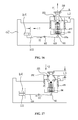
- a toner cartridge C may be mounted in an electronic imaging device (not shown) along X1 direction (the X1 direction is approximately perpendicular to the axial direction of the developing unit).
- Guide rails (F 11 , F 21 ) on left and right inner side panels of the electronic imaging device may be configured to support and guide the toner cartridge C to enter the electronic imaging device.
- a drive assembly 100 disposed at one side of the toner cartridge C can also be moved along the X1 direction to be in contact and engaged with a drive unit 900 of the electronic imaging device.
- the drive unit 900 is relatively fixed in the electronic imaging device and is only rotatable along the axis of the drive unit 900 . As the drive assembly 100 moves along the X1 direction to engage with the drive unit 900 , it may be possible that the rotation-driving-force receiving assembly 110 of the drive assembly 100 structurally interferes with the drive unit 900 .
- the rotation-driving-force receiving assembly 110 when the rotation-driving-force receiving assembly 110 is structurally interfering with the drive unit 900 , with pressure from the drive unit 900 , the rotation-driving-force receiving assembly 110 can be contracted inward in the axial direction of the rotation-driving-force receiving assembly 110 , so that the structural interference may be avoided.
- the rotation-driving-force receiving assembly 110 is further moved till approximately coaxial with the drive unit 900 , the structural interference between the rotation-driving-force receiving member 110 and the drive unit 900 may be avoided. Because of an elastic force of a spring disposed in the drive assembly 100 , the rotation-driving-force receiving assembly 110 can protrude to be in contact and engaged with the drive unit 900 .
- the electronic imaging device After the toner cartridge is mounted in the electronic imaging device (not shown), to ensure the electronic imaging device can function well, it is usually necessary to trigger an inspection device to inspect whether the toner cartridge C is mounted correctly. However, there is no simple and effective approach to trigger the inspection device.
- the present disclosure provides a toner cartridge and an electronic imaging device to solve technical problems of inspecting whether a matching toner cartridge is correctly mounted into an electronic imaging device, when the toner cartridge is mounted into the electronic imaging device.
- a technical solution according to the present disclosure is to provide a toner cartridge.
- the toner cartridge can be removably mounted in an electronic imaging device.
- the electronic imaging device may include a rotatable toner cartridge guide rail, and the toner cartridge can be mounted at the toner cartridge guide rail.
- a locating column may be disposed at one side of the toner cartridge, and the locating column can be supported by the toner cartridge guide rail. The locating column can be moved by an external force to rotate the toner cartridge guide rail.
- the electronic imaging device may also include an inspection device, which includes a trigger switch. When the toner cartridge is rotated because of the external force exerting on the locating column, the toner cartridge guide rail may touch the trigger switch and turn on the trigger switch.
- a side panel may be disposed at one side of the toner cartridge, and the locating column can be slid relative to the side panel.
- a slider may be disposed on the side panel, and the locating column may be disposed on the slider. Under the external force, the slider can drive the locating column to slide relative to the side panel.
- the slider may include a protrusion, and a chute may be disposed on the side panel. Through the protrusion, the slider can be slid on the chute of the side panel.
- the toner cartridge may further include a developing unit. Compared to the location of a slider slid by the external force, the slider may be located closer to the developing unit before the external force is applied for sliding the slider.
- an elastic resetting part may be further disposed between the slider and the side panel.
- the resetting part is configured to reset the slider when no external force exerting on the slider.
- the slider may further include a cartridge action part.
- the cartridge action part can be moved by an external force to cause the slider to drive the locating column to move.
- the cartridge action part may be disposed on the slider and protrude downward.
- the cartridge action part may have a protruding rod-shaped or hook-shaped structure.
- the cartridge action part and the slider may be integrally or separately configured.
- the electronic imaging device may include a pulling part, and the pulling part may be configured to drag the cartridge action part to move.
- a driving-force receiving member may be disposed at one side of the toner cartridge and configured to receive a rotation driving force from the drive unit of the electronic imaging device.
- the driving-force receiving unit and the locating column may be disposed at the same side of the toner cartridge.
- the toner cartridge may further include a flange.
- the flange may be configured receive the rotation driving force from the driving-force receiving member, and the driving-force receiving member can be extended and contracted relative to the flange.
- a claw may be disposed at an upper end of the driving-force receiving member, and the claw may be tilted or swung relative to the driving-force receiving member.
- the toner cartridge may further include a control mechanism, and the control mechanism may be configured to control the driving-force receiving member to extend and contract.
- the cartridge action part when subjected to a force, may be configured to push the control mechanism, so that the control mechanism can control the driving-force receiving member to extend and contract.
- the toner cartridge may include a developing chamber, and the side panel is fixed to one side of the developing chamber.
- the developing chamber and the side panel may not be rotatable along with a rotation of the toner cartridge guide rails.
- the technical solutions provided by the embodiments of the present application can achieve a beneficial effect: using the above technical solutions, whether the toner cartridge is correctly mounted can be determined by a conduction state of the inspection device.
- FIG. 1 is a schematic diagram of a toner cartridge mounted in an electronic imaging device.
- FIG. 2 is a schematic diagram of a drive assembly of a toner cartridge being engaged with a drive unit of an electronic imaging device.
- FIG. 3 is a schematic structural diagram of an toner cartridge and drive assembly according to a first exemplary embodiment of the present disclosure.
- FIG. 4 is a schematic structural diagram of another toner cartridge and drive assembly according to a first exemplary embodiment of the present disclosure.
- FIG. 5 is a schematic structural diagram of a pressing element of a drive assembly according to a first exemplary embodiment of the present disclosure.
- FIG. 6 is a schematic structural diagram of a slider of the drive assembly according to a first exemplary embodiment of the present disclosure.
- FIG. 7 a and FIG. 7 b illustrate a schematic structural diagram of an end cap of a toner cartridge according to a first exemplary embodiment of the present disclosure.
- FIG. 8 is a schematic structural diagram of a flange of a drive assembly according to a first exemplary embodiment of the present disclosure.
- FIG. 9 , FIG. 10 and FIG. 11 are schematic diagrams of a displacement operation of a driving-force receiving member according to a first exemplary embodiment of the present disclosure.
- FIG. 12 and FIG. 13 are schematic diagrams of extending and contracting operations of a driving-force receiving member according to a first exemplary embodiment of the present disclosure.
- FIG. 13 a is a schematic side view of a toner cartridge according to a first exemplary embodiment of the present disclosure.
- FIG. 14 is a schematic structural diagram of a toner cartridge and a photosensitive assembly according to a first exemplary embodiment of the present disclosure.
- FIG. 15 , FIG. 16 and FIG. 17 are schematic diagrams of structure and operation process of a control mechanism using Control Mode 1 according to a first exemplary embodiment of the present disclosure.
- FIG. 18 , FIG. 19 , FIG. 20 and FIG. 21 are schematic diagrams of structure and operation process of a control mechanism using Control Mode 2 according to a first exemplary embodiment of the present disclosure.
- FIG. 22 , FIG. 23 , FIG. 24 , FIG. 25 and FIG. 26 are schematic diagrams of structure and operation process of a control mechanism using Control Mode 3 according to a first exemplary embodiment of the present disclosure.
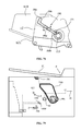
- FIG. 27 is a schematic diagram of an internal structure of an electronic imaging device according to a first exemplary embodiment of the present disclosure.
- FIG. 28 is a schematic diagram of a displacement operation of a toner cartridge guide rail of an electronic imaging device according to a first exemplary embodiment of the present disclosure.
- FIG. 29 and FIG. 30 are schematic diagrams of a toner cartridge and a photosensitive assembly that are mounted in an electronic imaging device according to a first exemplary embodiment of the present disclosure.
- FIG. 31 is a schematic diagram of extending and contracting operations of a drive unit of an electronic imaging device according to a first exemplary embodiment of the present disclosure.
- FIG. 32 and FIG. 33 are schematic structural diagrams of front ends of a drive assembly and a toner cartridge guide rail according to a first exemplary embodiment of the present disclosure.
- FIG. 34 is a schematic diagram of a driving-force receiving member being pressed to contract inward according to a first exemplary embodiment of the present disclosure.
- FIG. 35 is a schematic diagram of a toner cartridge and a photosensitive assembly in an electronic imaging device according to a first exemplary embodiment of the present disclosure.
- FIG. 36 is a schematic diagram of a driving-force receiving member being in contact and engaged with a drive unit according to a first exemplary embodiment of the present disclosure.
- FIG. 37 is a schematic diagram of a toner cartridge cooperated with a photosensitive assembly during the developing operation process according to a first exemplary embodiment of the present disclosure.
- FIG. 38 and FIG. 39 are schematic diagrams of a pulling part dragging a control action part to cause a driving-force receiving member to contract inward according to a first exemplary embodiment of the present disclosure.
- FIG. 40 a and FIG. 40 b are schematic diagrams of a pulling part dragging a powder acting member to make a toner cartridge move according to a first exemplary embodiment of the present disclosure.
- FIG. 41 is a schematic diagram of a photosensitive unit separating from a developing unit according to a first exemplary embodiment of the present disclosure.
- FIG. 41 and FIG. 42 are schematic diagrams of a photosensitive unit separating from a developing unit according to a first exemplary embodiment of the present disclosure.
- FIG. 43 and FIG. 44 are schematic diagrams of a driving-force receiving member contracting inward because of a rear end of the toner cartridge guide rail according to a first exemplary embodiment of the present disclosure.
- FIG. 45 is a schematic structural diagram of a toner cartridge and a photosensitive assembly according to a second exemplary embodiment of the present disclosure.
- FIG. 46 and FIG. 47 are schematic diagrams of a toner cartridge separating from a photosensitive assembly according to a second exemplary embodiment of the present disclosure.
- FIG. 48 is a schematic structural diagram of a driving-force receiving member according to a third exemplary embodiment of the present disclosure.
- FIG. 49 is a schematic diagram of a driving-force receiving member being in contact and engaged with a drive unit according to a third exemplary embodiment of the present disclosure.
- FIG. 50 is a schematic diagram of a claw of a driving-force receiving member being pressed to swing according to a third exemplary embodiment of the present disclosure.
- FIG. 51 is a schematic diagram of a driving-force receiving member being engaged with a drive unit to receive driving force according to a third exemplary embodiment of the present disclosure.
- FIG. 52 is a schematic diagram of a claw of a driving-force receiving member being pressed to swing according to a third exemplary embodiment of the present disclosure.
- FIG. 53 is a schematic structural diagram of a resetting part of a driving-force receiving member according to a forth exemplary embodiment of the present disclosure.
- FIG. 54 a and FIG. 54 b are schematic structural diagrams of a resetting part according to a forth exemplary embodiment of the present disclosure.
- FIG. 55 is a schematic diagram of a driving-force receiving member after being reset position but before being engaged with the drive unit according to a forth exemplary embodiment of the present disclosure.
- FIG. 56 is a schematic diagram of a driving-force receiving member abutting against and interfering with the drive unit according to a forth exemplary embodiment of the present disclosure.
- FIG. 57 is a schematic structural diagram of a toner cartridge and a cartridge action part according to a fifth exemplary embodiment of the present disclosure.
- FIG. 58 is a schematic structural diagram of a driving-force receiving member and a control mechanism according to a fifth exemplary embodiment of the present disclosure.
- FIG. 59 is a schematic structural diagram of a toner cartridge according to a sixth exemplary embodiment of the present disclosure.
- FIG. 60 and FIG. 61 are schematic structural diagrams of a side panel and a slider of a toner cartridge according to a sixth exemplary embodiment of the present disclosure.
- FIG. 62 and FIG. 63 are schematic diagrams of a displacement operation of a slider according to a sixth exemplary embodiment of the present disclosure.
- FIG. 64 and FIG. 65 are schematic diagrams of a toner cartridge being mounted in an electronic imaging device according to a sixth exemplary embodiment of the present disclosure.
- FIG. 66 is a schematic diagram of a slider being dragged by a pulling part according to a sixth exemplary embodiment of the present disclosure.
- FIG. 67 is a schematic structural diagram of a developing unit according to a sixth exemplary embodiment of the present disclosure.
- FIG. 68 is a schematic structural diagram of a toner cartridge being integrally configured with a photosensitive assembly according to a sixth exemplary embodiment of the present disclosure.
- FIG. 69 and FIG. 70 are schematic diagrams of operations of a toner cartridge and a photosensitive assembly according to a sixth exemplary embodiment of the present disclosure.
- FIG. 70 a 1 , FIG. 70 a 2 , and FIG. 70 a 3 are schematic structural diagrams of a toner cartridge according to a seventh exemplary embodiment of the present disclosure.
- FIG. 70 b is a schematic structural diagram of a slider of a toner cartridge according to a seventh exemplary embodiment of the present disclosure.
- FIG. 70 c is a schematic structural diagram of a control mechanism of a toner cartridge according to a seventh exemplary embodiment of the present disclosure.
- FIG. 70 d 1 , FIG. 70 d 2 and FIG. 70 d 3 are schematic diagrams of a first position of a toner cartridge according to a seventh exemplary embodiment of the present disclosure.
- FIG. 70 e 1 and FIG. 70 e 2 are schematic diagrams of a second position of a toner cartridge according to a seventh exemplary embodiment of the present disclosure.
- FIG. 70 f 1 , FIG. 70 f 2 , FIG. 70 f 3 and FIG. 70 f 4 are schematic diagrams of a third position of a toner cartridge according to a seventh exemplary embodiment of the present disclosure.
- FIG. 71 is a schematic structural diagram of a toner cartridge being integrally configured with a photosensitive assembly according to an eighth exemplary embodiment of the present disclosure.
- FIG. 72 is a schematic mounting diagram of a toner cartridge being integrally configured with a photosensitive assembly according to second, sixth and eighth exemplary embodiments of the present disclosure.
- FIG. 73 and FIG. 74 are schematic structural diagrams of a guide surface of a toner cartridge according to first to eighth exemplary embodiments of the present disclosure.
- FIG. 75 is a schematic diagram of a toner cartridge guide rail of an electronic imaging device according to first to eighth exemplary embodiments of the present disclosure.
- FIG. 76 is a schematic structural diagram of a force transmission element of a toner cartridge according to first to eighth exemplary embodiments of the present disclosure.
- FIG. 77 a , FIG. 77 b , FIG. 77 c , and FIG. 77 d are schematic diagrams of the operation of a force transmission element of a toner cartridge according to first to eighth exemplary embodiments of the present disclosure.
- FIG. 78 is a schematic diagram of another structure of a force transmission element of a toner cartridge according to first to eighth exemplary embodiments of the present disclosure.
- FIG. 79 is a schematic diagram of an internal structure of an electronic imaging device according to a ninth exemplary embodiment of the present disclosure.
- FIG. 80 a , FIG. 80 b and FIG. 81 are schematic structural diagrams of a slider of a toner cartridge according to a ninth exemplary embodiment of the present disclosure.
- FIG. 82 a , FIG. 82 b and FIG. 82 c are schematic diagrams of the operation of a slider of a toner cartridge according to a ninth exemplary embodiment of the present disclosure.
- FIG. 83 , FIG. 84 a and FIG. 84 b are schematic diagrams of the structure and operation of slider of a toner cartridge according to a ninth exemplary embodiment of the present disclosure.
- FIG. 85 is a schematic structural diagram of a slider of a toner cartridge according to a ninth exemplary embodiment of the present disclosure.
- the present disclosure relates to the field of electronic imaging technology, and more particularly, to a toner cartridge.
- the toner cartridge can be removably mounted in an electronic imaging device via a rotatable toner cartridge guide rail configured in the electronic imaging device.
- a locating column may be disposed at one side of the toner cartridge.
- the locating column can be supported by the toner cartridge guide rail and rotate the toner cartridge guide rail when the locating column is moved by an external force.
- the toner cartridge may also include an inspection device, which may have a trigger switch and be disposed in the electronic imaging device. When the toner cartridge guide rail is rotated in response to the external force on the locating column, the toner cartridge guide rail may touch the trigger switch and turn on the trigger switch.
- an axial direction of a toner cartridge b may be the same as an axial direction of a developing unit 30 or a photosensitive unit 10 of the photosensitive assembly a.
- a mounting direction of the toner cartridge b in an electronic imaging device may be substantially perpendicular to an axial direction of the toner cartridge b.
- an unmounting (or removal or taking out) direction of the toner cartridge b from the electronic imaging device may be opposite to the mounting direction of the toner cartridge b.
- FIG. 3 is a schematic structural diagram of a toner cartridge b.
- the toner cartridge b may include a developing chamber b 100 and side panels b 1 and b 2 disposed at both sides of the developing chamber b 100 .
- the developing chamber b 100 may accommodate a drive assembly 200 , which may be configured to be engaged with the drive unit 900 of the electronic imaging device and receive the rotation driving force.
- the drive assembly 200 may be mounted on the side panel b 2 .
- a photosensitive assembly a may be configured to cooperate with the toner cartridge b to execute a developing operation.
- the photosensitive assembly a may include a photosensitive chamber a 100 and a driving element a 110 that is disposed at a side of the photosensitive chamber a 100 .
- the driving element a 100 may be engaged with another drive unit 900 a of the electronic imaging device, receive the rotation driving force and send the rotation driving force to a photosensitive unit 10 of the photosensitive chamber a 100 .
- the driving element a 110 may be in an outward convex triangular structure.
- the drive assembly 200 may be disposed in the side panel b 2 of the developing chamber b 100 .
- the drive assembly 200 may include a driving-force receiving member 210 , a flange 270 , a pressing element 220 , a slider 230 , an elastic element 250 , and a connecting part 260 .
- the driving-force receiving member 210 may include a connecting member 216 , a claw 211 , and a notch 215 .
- a slot and a limiting surface may be disposed at the center of the connecting member 216 .
- the claw 211 may be disposed at one side of the connecting member 216 and configured to abut against and engage with a drive column 910 of the drive unit 900 .
- the notch 215 may be disposed at the other side of the connecting member 216 .
- the pressing element may have a hollow frame structure.
- a sliding surface 224 may be disposed at a side surface of the pressing element 220
- a pressure receiving element 221 may be disposed at an upper end of the pressing element 220 and the pressure receiving element 221 may include a curved or an inclined surface.
- the pressing element 220 may also include a pair of sliding blocks 223 .
- the slider 230 may have a trapezoidal structure with a narrower upper width. The upper surface of the slider 230 may abut against the limiting surface of the driving-force receiving member 210 .
- Inclined sliding surfaces 231 may be disposed on side surfaces of the slider 230 and chutes 232 may be disposed on the two opposite side surfaces of the slider 230 .
- the slider 230 may also include a through hole 236 .
- a through port 299 may be disposed at the center of an end cap 290 .
- An inclined sliding surface 291 and a vertical sliding surface 294 may be disposed inward around the port 299 . Because of the inclined configuration of the inclined sliding surface 29 , the through port 299 of the end cap 290 may have a structure with a smaller outer width (i.e., an inner width W 2 may be larger than an outer width W 1 , as shown in FIG. 7 ).
- the flange 270 may be a cylindrical structure and include a cavity 272 .
- a gear surface 271 may be disposed on the surface of the flange 270 and configured to transmit the driving force.
- a bottom surface 275 may be disposed at the bottom of the cavity 272 , and the cavity 272 may also include a pair of limiting chutes 273 .
- Each of the limiting chutes 273 may be constructed by two protrusions and include a chute 273 a .
- the connecting part 260 may have a centrally projecting crank-shaped structure.
- assembly relationships between the above-described parts/components may be as following.
- the pressing element 220 can be translationally sliding matched with the chute 232 that may be disposed on two side surfaces of the slider 230 .
- the driving-force receiving member 210 can pass the through hole 236 of the slider 230 and the pressing element 220 , and the limiting surface of the driving-force receiving member 210 can abut against the top surface of the slider 230 .
- a buckle 219 can be engaged with the slot of the driving-force receiving member 210 that protrudes form the slider 230 , so that the driving-force receiving member 210 can be axially fixed on the slider 230 .
- the connecting part 260 can pass the notch 215 that is disposed at one side of the connecting member 216 , and the middle protrusion of the connecting part 260 can be placed (or in some cases inserted) in the notch 215 .
- the elastic element 250 can be placed in the cavity 272 of the flange 270 .
- Two ends of the connecting part 260 can be placed in the limiting chute 273 that is included by the flange 270 .
- One end of the elastic element 250 can abut against the bottom surface 275 of the cavity 272 , and the other end can abut against two ends of the connecting part 260 .
- the above parts/components can be assembled and integrally mounted on the side panel b 2 of the toner cartridge b.
- the flange 270 can transmit the driving force to a gear 35 and drive the developing unit 30 to operation.
- the end cap 290 can cover on the slider 230 , and the driving-force receiving member 210 can protrude outward from a through port 299 of the end cap 290 .
- the inclined sliding surface 231 of the slider 230 can abut against the inclined sliding surface 291 that is included in the end cap 290 .
- the sliding surface 224 of the pressing element 220 can be vertically sliding matched with the sliding surface 294 of the end cap 290 .
- the end cap 290 can be mounted on the side panel b 2 of the toner cartridge b by threading, glutting or wielding, etc.
- one end of the elastic element 250 may abut against the connecting part 260 and two ends of the connecting part 260 can be placed (in some cases inserted) in the limiting chute 273 , so that the connecting part 260 can be elastically movable along the limiting chute 273 , and the driving-force receiving member 210 that is connected to the connecting part 260 may also be extended and contracted elastically relative to the flange 270 .
- the slider 230 may be connected to the driving-force receiving member 210
- the pressing element 220 may be connected to the slider 230 , therefore, the slider 230 and the pressing element 220 can also be moved along with the movement of the driving-force receiving member 210 .
- the driving-force receiving member 210 can be axially extended and contracted by the elastic force along a direction Y (the direction Y may be approximately coaxial or coincident with the axial direction of the developing unit 30 or the photosensitive unit 10 , and approximately perpendicular to the direction X).
- the driving-force receiving member 210 disposed in the drive assembly 200 can implement the following operation process (to facilitate understanding the operation process of the driving-force receiving member 210 in the flange 270 , some parts of the drive assembly 200 are not shown).
- the driving-force receiving member 210 Under the elastic force of the elastic element 250 , the driving-force receiving member 210 can be axially extended and contracted along the direction Y.
- the driving-force receiving member 210 As shown in FIG. 9 , which is viewed from a lengthwise direction of the connecting part 260 , the driving-force receiving member 210 can be assembled and matched with the connecting part 260 through the notch 215 .
- the driving-force receiving member 210 can be slidable along the lengthwise direction of the connecting part 260 , i.e., in the flange 270 , the driving-force receiving member 210 can achieve a parallel displacement of certain distance relative to the rotation axis of the flange 270 .
- the connecting part 260 has a centrally protruding crank-shaped structure, and two ends of the connecting part 260 can be placed (in some cases inserted) in the chute 273 .
- the driving-force receiving member 210 can be engaged with the connecting part 260 through the notch 215 and swing left and right through the centrally protruding crank-shaped structure of the connecting part 260 , i.e., in the flange 270 , the driving-force receiving member 210 can achieve a parallel displacement of certain distance relative to the rotation axis of the flange 270 .
- the driving-force receiving member 210 can be kept protruding outward by the elastic force of the elastic element 250 , and the pressure receiving element 221 of the pressing element 220 can also protrude outward relative to the outer surface of the end cap 290 .
- the driving-force receiving member 210 is in an initial position.
- the pressure receiving element 221 is pressed by an external force F 1
- the pressing element 220 can be pressed to move downward to drive the slider 230 .
- the slider 230 can drive the driving-force receiving member 210 to move downward along the direction Y and compress the elastic element 250 .
- the driving-force receiving member 210 is in a contracting position.
- a height H 1 from the top of the driving-force receiving member 210 in the initial position to the outer surface of the end cap 290 is greater than a height H 2 from the top of the driving-force receiving member 210 in the contracting position to the outer surface of the end cap 290 .
- FIG. 13 shows a side view of the toner cartridge b.
- a rotation axis of a toner feed unit 40 may be disposed within the contour projection range of the flange 270 , or the metal shaft 45 of the toner feed unit 40 maybe at least partially overlap with the flange 270 .
- a control member of the drive unit 200 may include a set of parts that enable the driving-force receiving member 210 to extend and contract relative to the flange 270 .
- the control member of the drive unit 200 or the set of parts may include the pressing element 220 , the slider 230 , and the elastic element 250 .
- FIG. 14 shows a side view of the toner cartridge b.
- a cartridge action part b 4 may be disposed at the bottom of the developing chamber b 100 of the toner cartridge b.
- the cartridge action part b 4 may have a rod-shaped or a hook-shaped structure projecting downward and outward.
- the cartridge action part b 4 can be connected to the developing chamber b 100 , or the side panel (b 1 or b 2 ) of the developing chamber b 100 .
- a control mechanism 600 can be disposed in the side panel b 2 of the toner cartridge b, and the control mechanism 600 may include a traction element 610 and a control action part 620 .
- the traction element 610 may be a traction cord.
- the control action part 620 may have a rod-shaped or a hook-shaped structure protruding downward and outward.
- One end of the traction element 610 can pass through a bottom hole 275 a of the flange 270 and be connected to the bottom of the driving-force receiving member 210 .
- the other end of the traction element 610 can be connected to the control action part 620 .
- the control action part 620 can be displaced by the driving-force receiving member 210 further than the cartridge action part b 4 in a X1 direction.
- the distance between the front end of the control action part 620 and the front end of the cartridge action part b 4 may be L 1 .
- the control action part can be moved by the external force F 2 in a X2 direction (opposite to the X1 direction), and through the traction 610 , drag the driving-force receiving member 210 to contract inward relative to the flange 270 .
- the control action part 620 is moved by the external force to be flush with the cartridge action part b 4 , the pressure receiving element 221 of the pressing element 220 may not protrude out of the outer surface of the end cap 290 .
- the elastic force provided by the compressed elastic element 250 can cause the driving-force receiving member 210 to protrude outward, and through the traction element 610 , drag the control action part 620 to the position before the external force is applied on the control action part. That is, the distance between the front end of the control action part 620 and the front end of the cartridge action part b 4 may be L 1 .
- the function of the control mechanism 600 can cause the driving-force receiving member 210 to be in an initial position.
- the driving-force receiving member 210 may be in a contracting position.
- a distance L 2 from the top of the claws 211 of a driving-force receiving member 210 in the initial position to the surface of the end cap 290 may be greater than a distance L 3 from the top of the claw 211 of a driving-force receiving member 210 in the contracting position to the surface of the end cap 290 .
- the control mechanism 600 may also include a revolving flange 611 that can make the traction element 610 to change direction.
- the control mechanism 600 may include a control action part 620 and a connecting member 630 .
- the control action part 620 and the connecting member 630 may be rotatably connected.
- the connecting member 630 may have an elongated rod-shaped structure.
- the front end of the connecting member 630 may have a fork-shaped structure and include an inclined surface 631 .
- the control mechanism 600 may further include a resetting part 810 (a rubber band or a tension spring). One end of the resetting part 810 may be connected to the control action part 620 , and the other end of the resetting part 810 may be connected to the side panel b 2 or the developing chamber b 100 .
- the connecting member 216 of the driving-force receiving member 210 may further include an elongated rod passing through the flange 270 .
- a distal end of the elongate rod may include a disc, and an inclined surface 216 a may be disposed on the disc.
- the control action part 620 and the connecting member 630 can be moved forward in the X1 direction by the elastic traction action of the resetting part 810 , and the inclined surface 631 of the connecting member 630 may not abut against the inclined surface 216 a at the distal end of the driving-force receiving member 210 .
- Control Mode 1 of the control mechanism 600 can be achieved by Control Mode 2.
- the control mechanism 600 may include a control action part 620 , a connecting member 621 , a positioning ring 640 , and a guide sleeve 650 .
- the front end of the connecting member 621 may include a connecting column 622 .
- the outer annular surface of the positioning ring 640 may include a matching hole 642 and the bottom of the positioning ring 640 may include an inclined surface 641 .
- the guide sleeve 650 may include an inclined surface 651 , a limiting hole 652 and a through hole 655 may be disposed at the center of the guide sleeve 650 .
- the control mechanism 600 and the driving-force receiving member 210 may be connected in the following manner.
- the positioning ring 640 can be placed on the guide sleeve 650 ; the inclined surface 641 may abut against and be matched with the inclined surface 651 ; an extended elongated rod body of the connecting member 216 can pass through the positioning ring 640 and the through hole 655 of the guide sleeve 650 ; a protrusion 216 b disposed at a distal end of elongated rod body can abut against the bottom of the guide sleeve 650 ; the connecting column 622 at the front end of the connecting member 621 can be rotatably connected to and matched with the matching hole 642 of the positioning ring 640 ; and the control mechanism may also include a resetting part 810 .
- the control action part 620 and the connecting member 621 can be moved forward in the X1 direction by the elastic traction of the resetting part 810 ; the inclined panel of the positioning ring 640 may not abut against the inclined surface 651 of the guide sleeve 650 ; and the positioning ring 640 may be matching attached to the guide sleeve 650 .
- the driving-force receiving member 210 is in the initial position.
- the connecting column 622 at the front end of the connecting member 621 can drag the matching hole 642 to rotate the positioning ring 640 .
- the inclined surface 641 may abut against the inclined surface 651 , so that the guide sleeve 650 may be moved downward and separated from the positioning ring 640 . Because the limiting hole 652 of the guide sleeve 650 is relatively positioned by the side panel b 2 or a protrusion b 2 a of the developing chamber b 100 , the guide sleeve 650 can be moved only along the axial direction but cannot be rotated relative to the axial direction.
- Control Mode 3 the same functions and effects of Control Mode 1/Control Mode 2 of the control mechanism 600 can be achieved by Control Mode 3.
- the cartridge action part b 4 and the control mechanism 600 are viewed from one side of the toner cartridge b or in the axial direction of the driving-force receiving member 210 .
- the cartridge action part b 4 and the control mechanism 600 may be disposed as one in front of another.
- the control mechanism 600 may be closer to the driving-force receiving member 210
- the cartridge action part b 4 may be closer to the rear end of the developing chamber b 100 .
- an electronic imaging device P may include a cover P 1 , a driving motor M 1 , a toner cartridge guide rail F 100 , a photosensitive assembly guide rail F 200 , a drive unit 900 , a drive unit 900 a , a pulling part F 300 , and a traction element F 120 (a rubber band or a tension spring).
- the drive unit 900 and the drive unit 900 a can be driven to rotate by the driving motor M 1 .
- the toner cartridge guide rail F 100 can be rotated around a rotation point F 101 relative to the photosensitive assembly guide rail F 200 .
- One end of the traction element F 120 may be connected to the front end of the toner cartridge guide rail F 100 , and the other end of the traction element F 120 may be fixedly connected in the electronic imaging device P.
- the front end of the toner cartridge guide rail F 100 may also include an elastically extendable stopper F 110 .
- the pulling part F 300 which may be disposed below the cartridge guide rail F 100 , can be driven to move certain front-and-rear displacement or certain rotation displacement by the driving motor M 1 or other driving mechanisms.
- the pulling part F 300 may have a hook-shaped structure.
- the toner cartridge guide rail F 100 when a force is exerting on the toner cartridge guide rail 100 , the toner cartridge guide rail F 100 can achieve certain amount of rotation relative to the rotation point F 101 and may be in a displacement position. Once the force is removed from the toner cartridge guide rail F 100 , the toner cartridge guide rail F 100 can be dragged by the pulling part F 120 to return to the initial position before the rotation.
- the electronic imaging device P may also include a front frame F 400 with an inclined surface.
- the front frame F 400 may be disposed at one side of the toner cartridge guide rail F 100
- the photosensitive assembly F 200 may be disposed at the other side of the toner cartridge guide rail F 100 .
- the electronic imaging device P may further include an inspection device PD 1 and a trigger switch SW 1 for enabling the inspection device PD 1 to perform an inspection operation.
- the toner cartridge guide rail F 100 may include a pushing block F 103 , and optionally, the pushing block F 103 can be disposed at a side where the driving assembly of the electronic imaging device P is located (e.g. the side of the guide rail F 11 close to the drive unit 900 , referring to the structure of the guide rail shown in FIG. 1 ).
- the pushing block F 103 of the toner cartridge guide rail F 100 can be rotated along with the rotation of the toner cartridge guide F 100 to touch the trigger switch SW 1 . So as that the inspection device PD 1 may start inspecting and generate a signal that the trigger switch SW 1 is turned on.
- the pushing block F 103 may no longer touch the trigger switch SW 1 . So as that the SW 1 may be turned off, and the inspection device PD 1 may generate a signal that the trigger switch SW 1 is turned off.
- the electronic imaging device P can determine whether a toner cartridge mounted by a user matches the electronic imaging device P. For example, if the toner cartridge mounted by the user matches the electronic imaging device P, the generated inspection signal can be “ON-OFF” or “ON-OFF-ON-OFF”. If the toner cartridge mounted by the user and the electronic imaging device P can complete an inspection process to generate the above inspection signal, the electronic imaging device P can automatically determine that a matching toner cartridge is mounted by the user, and the electronic imaging device P may display that the inspection process is completed so that the user can perform normal developing operation (printing). If the inspection process cannot be completed, for example, only “ON” or “OFF” signal is generated, the electronic imaging device P may display that the inspection process is not completed, and the normal developing operation (printing) cannot be performed.
- the pulling part F 300 of the electronic imaging device P acts on the cartridge action part b 4 , the pulling part F 300 may need to be moved forward to the front of the cartridge action part b 4 and moved backward to act on the cartridge action part b 4 . Therefore, there may be several displacement modes of the pulling piece F 300 as following.
- the photosensitive assembly a and the toner cartridge b can be mounted in the electronic imaging device P.
- the drive unit 900 a may be contracted inward along the rotation axis of the drive unit 900 a . Therefore, during the mounting processing of the photosensitive assembly a into the electronic imaging device P along the photosensitive assembly guide rail F 200 , the driving element a 110 of the photosensitive assembly a may not structurally interfere with the drive unit 900 a.
- the drive unit 900 which is engaged with the driving-force receiving member 210 , can only be rotated along the rotation axis of the electronic imaging device P in the electronic imaging device P, but cannot be contracted and extended axially as the drive unit 900 a . Therefore, when the toner cartridge b is mounted into the electronic imaging device P, it may be necessary to prevent the driving-force receiving member 210 from structurally interfering with the drive unit 900 .
- the toner cartridge b can be mounted into the electronic imaging device P along the toner cartridge guide rail F 100 in the mounting direction, i.e., the X1 direction.
- the pressing element member 221 of the drive assembly 200 may abut against and press the front end of the toner cartridge guide rail F 100 , so that the whole pressing element 220 can be moved downward relative to the end cap 290 .
- the pressing element 220 moving downward can push the slider 230 to move downward, and the slider 230 moving downward can push the driving-force receiving member 210 to contract inward relative to the flange 270 .
- the driving-force receiving member 210 when the driving-force receiving member 210 is in the contraction position, during the mounting process of the toner cartridge b, the driving-force receiving member 210 may not structurally interfere with the drive unit 900 , and there may be a gap H 3 between the top of the driving-force receiving member 210 and the bottom of the drive unit 900 .
- the driving-force receiving member 210 When the toner cartridge b is correctly mounted into the electronic imaging device P along the toner cartridge guide rail F 100 , the driving-force receiving member 210 may be approximately coaxial with the drive unit 900 .
- the pressure receiving element 221 may be moved to the rear end F 100 b of the toner cartridge guide rail F 100 and no longer under pressure. As shown in FIG. 35 and FIG.
- the connecting part 260 may be pushed by the elastic force released from the elastic element 250 , and the driving-force receiving member 210 may be pushed by the connecting part 260 to protrude outward to engage with the drive unit 900 .
- the driving-force receiving member 210 protrudes outward, the slider 230 and pressing element 220 that are engaged with the driving-force receiving member 210 may also be slid outward to the position before the slider 230 and the pressing element 220 are pressed.
- the drive unit 900 a may protrude out along the rotation axis of the drive unit 900 a and may be in contact and engaged with the driving element a 110 of the photosensitive assembly a.
- the driving motor M 1 can drive the drive unit 900 and the drive unit 900 a to rotate.
- the driving-force receiving member 210 can receive the rotation driving force from the drive unit 900 and transmit the rotation driving force to the flange 270 .
- the flange 270 can transmit the driving force to the gear 35 for driving the operation of developing unit 30 .
- the drive unit 900 a may drive the driving element a 110 to rotate for driving the photosensitive unit 10 to operate.
- the toner cartridge b and the photosensitive assembly a can be supported and positioned by the toner cartridge guide rail F 100 and the photosensitive assembly guide rail F 200 , respectively.
- a locating column b 21 disposed at the front end of the side panel b 2 first may abut against the stopper F 110 and press down on the stopper F 110 , so that the mounting process of the toner cartridge b along the toner cartridge guide rail F 100 can be continued.
- the locating column b 21 may be moved to the front end of the toner cartridge guide rail F 100 and no longer press the stopper F 110 .
- the stopper F 110 may be moved upward by the elastic force and retuned to a position where the stopper F 110 is not pressed, as shown in FIG. 35 .
- the stopper may have certain elastic force to prevent the backward movement of the locating column b 21 , so that the entire toner cartridge b can be positioned on the toner cartridge guide rail F 100 to prevent the developing quality being affected by the shaking of the toner cartridge b during the developing operation.
- FIG. 37 schematically shows the photosensitive unit 10 is rotated and engaged with the developing unit 30 to perform developing operation, i.e., the toner being transmitted from the developing chamber b 100 and printed on a paper S through the photosensitive unit 10 and the developing unit 30 .
- the driving motor M 1 may simultaneously drive both of the drive unit 900 and driving nit 900 a to rotate.
- the photosensitive unit 10 may need to be separated from the developing unit 30 by a certain distance, preventing the toner from being transmitted to the photosensitive unit 10 when the developing operation is not performed, therefor, the toner can be prevented from being wasted.
- the locations of the drive unit 900 and the drive unit 900 a of the electronic imaging device P may be relatively fixed (i.e., a planar movement cannot be performed). Therefore, to separate the photosensitive unit 10 from the developing unit 30 , it may be necessary to at least separate drive unit 900 from the driving-force receiving member 210 that is engaged with the drive unit 900 .
- the pulling part F 300 that is disposed below the toner cartridge guide rail F 100 can be triggered to be moved.
- the cartridge action part b 4 may be disposed in front of the control mechanism 600 .
- the pulling part F 300 when the pulling part F 300 is moved backward (i.e., moved toward the rear end of the developing chamber b 100 of the toner cartridge b), the pulling part F 300 with a hook-shaped structure may act on the control mechanism 600 .
- the pulling part F 300 may drag control action part 620 of the control mechanism 600 , so that the driving-force receiving member 210 may be contracted inward relative to the flange 270 to be separated from the drive unit 900 .
- the process of the driving-force receiving member 210 being controlled by the control mechanism 600 to contract can refer to the structure and process of the Control Mode 1/Control Mode 2/Control Mode 3 of the control mechanism 600 , and is not elaborated herein.
- the pulling part F 300 which is dragging (hooked on) the control action part 620 may still need to be further moved backward to act on the cartridge action part b 4 .
- the pulling part F 300 can also simultaneously drag (hook on) the cartridge action part b 4 and the control mechanism 600 .
- the toner cartridge b is relatively positioned on the toner cartridge guide rail F 100 .
- the pulling part F 300 drags the cartridge action part b 4 to move the toner cartridge b because the toner cartridge b has been relatively positioned on the toner cartridge guide rail F 100 . Therefore, when the toner cartridge b is dragged, the toner cartridge b can be rotated along with the toner cartridge guide rail F 100 around the rotation point F 101 of the toner cartridge guide rail F 100 . In this case, the driving-force receiving member 210 and the drive unit 900 can be separated. Therefore, during the rotation process of the toner cartridge b and the toner cartridge guide rail F 100 , the driving-force receiving member 210 may not structurally interfere with the relatively fixed drive unit 900 .
- the locating column b 21 of the toner cartridge b can also be stopped by the elastic stopper F 110 , so that the entire toner cartridge b can be positioned on the toner cartridge guide rail F 100 . Therefore, during the rotation process of the toner cartridge b and the toner cartridge guide rail F 100 , the toner cartridge b is not easily to be shaken due to being detached from the toner cartridge guide rail F 100 under an action of a pulling force.
- FIG. 41 schematically shows the photosensitive unit 10 being separated from the developing unit 30 with a gap G between each other, after the cartridge action part b 4 and the control mechanism 600 are dragged by the pulling part F 300 .
- the driving motor M 1 may continue to drive the drive unit 900 and the drive unit 900 a to rotate for a certain time, and the drive unit 900 a may continue to drive the driving element a 110 to rotate, while the drive unit 900 may be disengaged with the driving-force receiving member 210 . Therefore, the driving-force receiving member 210 may not drive the developing unit to operate, so that when the developing operation is not performed, the toner can be prevented from wasting. Further, the separation of the photosensitive unit 10 from the developing unit 30 can prevent the contact abrasion that occurs when the developing operation is not performed.
- the toner cartridge b can be rotated, so that the toner cartridge guide rail F 100 can be rotated clockwise relative to the photosensitive assembly guide rail F 200 , and the signal that the trigger switch SW 1 is turned on can be generated.
- the pulling part F 300 may need to be moved in the opposite direction to return to the position before displacement. That is, the pulling part F 300 may need to be moved away from the rear end of the developing chamber b 100 , and at this time, and the pulling part F 300 may not act on the cartridge action part b 4 .
- the traction element F 120 at the front end of the toner cartridge guide rail F 100 may generate a traction force to drag the toner cartridge guide rail F 100 to move toward the photosensitive assembly guide rail F 200 and return to the initial position before rotation.
- the toner cartridge b that is supported and positioned by the toner cartridge guide rail F 100 may also be moved toward the photosensitive assembly a that is supported and positioned by the photosensitive assembly guide rail F 200 , and the photosensitive unit 10 may be reconnected to the developing unit 30 .
- the pulling part F 300 is further moved in the opposite direction till the pulling part F 300 does not act on the control mechanism action part 620 of the control mechanism 600 , the elastic force released by the elastic element 250 of the flange 270 can cause the driving-force receiving member 210 to protrude outward and engage with the drive unit 900 again.
- each part may return to the position before the pulling part F 300 is triggered to act, and the developing operation in the electronic imaging device P can be resumed.
- the toner cartridge guide rail F 100 and the toner cartridge b may be rotated together as a whole. Therefore, when the pulling part F 300 is acting on the toner cartridge b, the toner cartridge b may not move relative to the toner cartridge guide rail F 100 , and the pressure receiving element 221 may not be abutted against and pressed downward by the rear end F 100 b of the toner cartridge guide rail F 100 .
- the axial contraction of the driving-force receiving member 210 may be controlled by the control mechanism 600 under the action of the pulling part F 300 .
- the contraction movement of the driving-force receiving member 210 may not be affected due to the pressure receiving element 221 being abutted against and pressed by the rear end F 100 b of the toner cartridge guide rail F 100 . Therefore, it may not be affected that the driving-force receiving member 210 engaging with and disengaging from the drive unit 900 .
- the toner cartridge guide rail F 100 may be rotated counterclockwise relative to the photosensitive assembly guide rail F 200 by the traction element F 120 , and the signal that the trigger switch is turned off may be generated.
- the process of removing the toner cartridge b from the electronic imaging device P can refer to the process of mounting the toner cartridge b into the electronic imaging device P, and can be an opposite operation of mounting the toner cartridge b into the electronic imaging device P.
- the toner cartridge b can be removed from the electronic imaging device P along the toner cartridge guide rail F 100 in the X2 direction that is opposite to mounting direction.
- the pressure receiving element 221 of the drive assembly 200 may abut against the rear end F 100 b of the toner cartridge guide rail F 100 , as the toner cartridge b is moved along the unmounting direction.
- the rear end F 100 b may press the pressure receiving element 221 to move downward in the Y2 direction and drive the driving-force receiving member 210 to contract inward, so that the driving-force receiving member 210 can be disengaged with the drive unit 900 . Therefore, when the toner cartridge b is removed from the electronic imaging device P, a structural interference due to the driving-force receiving member 210 tightly engaged with the drive unit 900 may not occur, so that it is not difficult to unmount the toner cartridge b. When the toner cartridge b is completely removed from the electronic imaging device P, the front end F 100 a of the toner cartridge guide rail F 100 may not press the pressure receiving element 221 of the drive assembly 200 . Therefore, because of the elastic force of the elastic element 250 , the pressure receiving element 221 and the driving-force receiving member 210 can protrude outward and return to the initial position before being pressed.
- the driving-force receiving member 210 can be contracted inward because of the rear end of the toner cartridge guide rail according to Exemplary Embodiment I of the present disclosure.
- the drive unit 900 may still be tightly engaged with the driving-force receiving member 210 . Therefore, the driving-force receiving member 210 may be difficult to be moved along the unmounting direction, while the flange 270 and the end cap 290 can be moved relative to the driving-force receiving member 210 .
- the inclined sliding surface 291 of the driving-force receiving member 210 can generate the compression force F 2 and press on the inclined sliding surface 231 of the slider 230 to drive the slider 230 to contract inward.
- the driving-force receiving member 210 that is fixed relative to the slider 230 can also be moved downward as the slider 230 is contracted.
- the pressing element 220 may also be pressed by the slider 230 to contract inward. Because of the sliding surface 294 of the end cap 290 , the sliding surface 224 of the pressing element 220 can be slid inward and kept vertical.
- the slider 230 and the driving-force receiving member 210 can be fixed and cooperate to keep the driving-force receiving member 210 vertical when the driving-force receiving member 210 is contracted inward. While moved, the rotation axis of driving-force receiving member 210 may be approximately coaxial or parallel to the rotation axis of the flange 270 .
- the driving-force receiving member 210 can contract inward relative to the end cap 290 and disengage with the drive unit 900
- the pressing element 221 of drive assembly 220 may be pressed by the rear end F 100 b of the toner cartridge guide rail F 100 so that the driving-force receiving member 210 can be contracted inward axially.
- the inclined sliding surface 291 of the end cap 290 may press on the inclined sliding surface 231 of slider 230 , so that the driving-force receiving member 210 can be contracted inward axially. Because of the above two contraction movement, it may be easier for the driving-force receiving member 210 to achieve axially disengagement after the driving-force receiving member 210 is tightly engaged with the drive unit 900 , which can prevent the structurally interference when the driving-force receiving member 210 is disengaged from the drive unit 900 .
- the drive unit 900 may be contracted inward along the rotation axial direction thereof to be disengaged from the drive unit 900 a of the photosensitive unit a, so that the photosensitive assembly a can be easily removed from the photosensitive assembly guide rail F 200 .
- the cartridge action part b 4 of the toner cartridge b and the control mechanism 600 may be disposed as one in front of another, therefore, during the photosensitive unit 10 being separated from the developing unit 30 , the pulling part F 300 may first act on the control mechanism 600 , so that the driving-force receiving member 210 can be contracted inward and separated from the drive unit 900 . Then the pulling part F 300 may act on the cartridge action part b 4 , so that the toner cartridge b can be rotationally separated from the photosensitive assembly a. There may be a certain timing difference between the pulling part F 300 acting on the control mechanism and the pulling part F 300 acting on the cartridge action part b 4 . When the pulling part F 300 stops acting and returns to the initial position, the pulling part F 300 may first stop acting on the cartridge action part b 4 and then stop acting on the control mechanism 600 .
- the toner cartridge b and the photosensitive assembly a described in exemplary Embodiment I are mutually independent, whereas, the toner cartridge b can also be connected to the photosensitive assembly a.
- a connecting arm b 3 a with a hole b 3 may be disposed on each of the side panel b 1 and b 2 of two sides of the toner cartridge b.
- the connecting arm b 3 a may include a locating column b 22 .
- the connecting arm b 3 a on the side panels b 1 and b 2 can extend into the two side ends of photosensitive chamber a 100 of the photosensitive assembly a.
- the top end of the elastic element a 4 may abut against the inner wall of photosensitive chamber a 100 and the bottom end of the elastic element a 4 may be inserted on the locating column b 22 .
- the toner cartridge b can be connected to the photosensitive assembly a.
- the toner cartridge b can achieve a certain amount of swinging relative to the photosensitive assembly a.
- the process of the photosensitive unit 10 being separated from and in contact with the developing unit 30 is similar to that described in Exemplary Embodiment I.
- the toner cartridge b and the photosensitive assembly a are mounted into the electronic imaging device P, under the action of the pulling part F 300 on the control mechanism 600 and the cartridge action part p 4 , the toner cartridge b can be rotated around the rotation point (the position of hole b 3 /connecting part a 3 b 22 ) relative to the photosensitive assembly, so that the photosensitive unit 10 can be separated from the developing unit 30 .
- the toner cartridge b can be rotated by the elastic force released from the elastic element a 4 , and the photosensitive unit 10 can be in contact with the developing unit 30 again.
- the connecting structure of the toner cartridge b and the photosensitive assembly a according to Exemplary Embodiment II can be used as an alternative to the structure of the rotatable toner cartridge guide rail F 100 of the electronic imaging device P described in Exemplary Embodiment I.
- the structure of some parts not shown according to Exemplary Embodiment II can refer to structure of the parts according to Exemplary Embodiment I and is not elaborated here.
- the driving-force receiving member 210 can be extended and contracted along the rotation axis thereof relative to the flange 270 or the end cap 290 to be engaged with and disengaged from the drive unit 900 .
- the matching mechanism can also be substituted by the following structure of the driving-force receiving member 210 to achieve a similar function and application.
- the claw 211 disposed at the upper end of the driving-force receiving member 210 can be tilted or swung relative to the driving-force receiving member 210 , i.e., the center line of the claw 211 may be tilted to a certain angle relative to the rotation axis of the driving-force receiving member 210 .
- the tilted angle can be between 5° and 65°.
- the outer surface of the claw 211 may include a smooth curved transition.
- the claw 211 may also include an elastic member 810 (a rubber band or a tension spring). One end of the elastic element 810 may be connected to the claw 211 , and the other end may be connected to the driving-force receiving member 210 .
- an outward inclined surface 212 may be disposed outward, and an inward inclined surface 213 may be disposed inward.
- the outward inclined surface 212 and the inward inclined surface 213 can be constructed by a certain curved surface and an arc surface.
- FIG. 49 and FIG. 50 schematically show a contacting engagement of the drive assembly 200 of the toner cartridge b with the drive unit 900 .
- the semicircular structure of a bottom 912 of the drive unit 900 can directly press on the swingable claw 211 or the outward inclined surface 212 , and the claw 211 can incline inward and/or generate a downward compression force F 2 to drive the driving-force receiving member 210 to contract inward along the Y2 direction, avoiding rigid structural interference with the drive unit 900 .
- the drive assembly 200 is continuously moved till the driving-force receiving member 210 is coaxial with the drive unit 900 , as shown in FIG.
- the bottom end 912 of the drive unit 900 may not abut against the claw 211 or the outward inclined surface 212 .
- the elastic force released by the elastic element 250 can push the driving receiving force 210 to protrude outward along the Y1 direction, and to be in contact and engaged with the drive unit 900 to receive the driving force.
- the claw 211 can abut against a drive column 910 , which may cause that the driving-force receiving member 210 is not completed engaging with the drive unit 900 .
- the drive column 910 may be rotated to avoid the claw 211 . Therefore, when the interference disappears, the driving-force receiving member 210 can continue to protrude outward to complete engagement with the drive unit 900 .
- the drive unit 900 may be relatively stationary.
- the claw 211 and the inward inclined surface 213 may be abutted against and pressed by a semicircular structure at the bottom of the drive unit 900 , so that the claw 211 can inward tilted and/or generate downward compression force F 2 , causing the entire driving-force receiving member 210 to contract inward along the Y2 direction to avoid the rigid structural interference with the drive unit 900 .
- the driving-force receiving member 210 may be returned to the initial position by the elastic force of the elastic element 250 and the claw 211 may be returned to an upright state before the compression by the elastic force of the elastic element 810 .
- the toner cartridge b can be mounted into and removed from the electronic imaging device P.
- the photosensitive unit 10 can be disengaged from and engaged with the developing unit 30 of the toner cartridge b in the electronic imaging device P.
- the driving-force receiving member 210 can realize the operation of engagement with and disengagement form the drive unit 900 . According to Exemplary Embodiment III, it may not be necessary to add the control mechanism 600 or drive assembly 200 described in the Exemplary Embodiment I/Exemplary Embodiment II to the toner cartridge b.
- the connecting member 216 of the driving-force receiving member 210 may further include a resetting part 216 c .
- the resetting member 216 c may include an elliptical structure or a non-circular cross-section (shown as cross-section B-B).
- the end cap 290 or the side panel b 2 may include a resetting part 291 , and the resetting part 291 may be an elastic metal ring, a rubber band, a torsion spring and a magnet, as shown in FIG. 54 a and FIG. 54 b.
- the resetting mechanism composed by the resetting part 291 and the resetting member 216 c of the driving-force receiving member 210 can reposition the claw 211 of the driving-force receiving member 210 .
- the resetting member 216 c can be applied with an elastic force by the resetting part 291 to rotate, and the rotating resetting member 216 c can drive the claw 211 to rotate.
- the claw 211 of the driving-force receiving member 210 can realize that one claw 211 a is higher than the other claw 211 b relative to the mounting direction X.
- the distance H 4 between the two claws may be greater than the outer cylindrical width H 5 of the drive unit 900 .
- the claw 211 according to Exemplary Embodiment IV cannot be swung or tilted relative to the driving-force receiving member 210 , because the distance between the claw 211 a and the claw 211 b can accommodate the outer cylindrical width of the drive unit 900 , when the driving-force receiving member 210 is engaging with the drive unit 900 , the outward inclined surface 212 of the driving-force receiving member 210 can be abutted against and pressed by bottom 912 with the semicircular structure of the drive unit 900 to contract inward relative to the flange 270 , so that the interference with the drive unit 900 can be avoided (referring to FIG. 50 ).
- the claw 211 may not abut against the drive column 910 of the drive unit 900 , therefore the
- the structure according to Exemplary Embodiment IV can be used in combination with the structure of the toner cartridge b according to Exemplary Embodiment I/Exemplary Embodiment II/Exemplary Embodiment III.
- the function achieved by the pulling part F 300 acting on the control action part 620 and the cartridge action part b 4 can also be achieved by directly using the cartridge action part b 4 . That is, the driving-force receiving member 210 can be controlled by the control mechanism 600 so that the driving-force receiving member 210 can be extended and contracted relative to the flange 270 .
- the toner cartridge b in the electronic imaging device P can be rotated relative to the photosensitive assembly a, so that the developing unit 30 can be separated from the photosensitive unit 10 .
- a barrier wall b 2 b rather than the cartridge action part b 4 disposed on the side panel according to the present exemplary embodiment.
- the barrier wall b 2 b may be disposed on the movement track of the control action part 620 and can abut against the control action part 620 . Therefore, the control action part 620 can achieve all functions of the cartridge action part b 4 according to Exemplary Embodiment I to Exemplary Embodiment V.
- the pulling part F 300 may first act on the control mechanism 600 .
- the pulling part F 300 may drag the control action part 620 of the control mechanism 600 , so that the driving-force receiving member 210 can be extended and contracted relative to the flange 270 to be separated from the drive unit 900 .
- the control action part 620 can be dragged by the pulling part F 300 to move along a designated path and be contact with the barrier wall b 2 b of the side panel b 2 .
- the control action part 620 can abut against the barrier wall b 2 b , so that the pulling force of pulling part F 300 can be converted to a pushing force on the barrier wall b 2 b , and the pushing force can push the side panel b 2 , causing the toner cartridge b to rotate relative to the photosensitive assembly a and being separated from the photosensitive assembly a, as shown in FIG. 41 .
- the control action part 620 may first retract the pushing force on the barrier wall b 2 b , as the pulling direction F 300 is moved in the opposite direction. As the toner cartridge b is rotated, the developing unit 30 can contact the photosensitive unit 10 again. Then the pulling part F 300 may further move backward, so that the pulling part F 300 cannot act (hook) on the control action part 620 of the control mechanism 600 . Because of the elastic force released by the elastic element 250 , the driving-force receiving member 210 can protrude out and reengage with the drive unit 900 .
- the function of the above embodiments can also be achieved by the control action part 620 in contact with the barrier wall b 2 b . That is, when the pulling part F 300 is triggered to act on the control action part 620 , the driving-force receiving member 210 can be first inward contracted. Then the toner cartridge b may be rotated relative to the photosensitive assembly a, so that the photosensitive unit 10 can be separated from the developing unit 30 . When the pulling part F 300 retracts action, the above action of the above parts can be repeated reversely.
- a buffer layer such as a sponge, a felt or a short spring, may be disposed on a contacting surface between the control action part 620 and the barrier wall b 2 b , so that there can be a buffer when the control action part 620 is in contact with the barrier wall b 2 b.
- the main difference from the above Exemplary Embodiment I to Exemplary Embodiment V, is the configuration of the cartridge action part b 4 .
- the structure of the drive assembly 200 may refer to the structure of the drive assembly described in Exemplary Embodiment I to Exemplary Embodiment V and is not be elaborated here.
- sliders b 1 c and b 2 c may be disposed at the outer side of the side panels b 1 and b 2 , respectively.
- the side panels b 1 and b 2 may disposed at sides of the developing chamber b 100 of the toner cartridge b.
- a protrusion b 2 c 1 may be disposed at the inner side of the slider b 2 c
- a chute b 2 d 1 may be disposed on the surface of the side panel b 2 .
- the slider b 2 c can be slid on the side panel b 2 along a direction that is perpendicular to the axial direction of the developing unit 30 .
- a cartridge action part b 4 may be disposed at the bottom of the slider b 2 c
- a locating column b 21 may be disposed on the side surface of the slider b 2 c .
- the slider b 1 c on the other side panel b 1 may also have basically the same structure and the function of the b 2 c .
- a positioning element b 120 may be disposed on the surface (upper) of the developing chamber b 100 .
- the positioning element b 120 may be outward convex cantilever, and a locating column b 121 may be disposed at the front end of the positioning element b 120 .
- the rear end of the developing chamber b 100 may include a pushing element b 110 that protrudes toward the chamber back of the developing chamber b 100 .
- the pushing element b 110 may be an elastic protrusion, e.g. a material with certain elastic amount, including elastic sponges, springs, plastic blocks, and magnets, etc.
- the slider b 2 c can be slid in the X2 direction relative to the side panel b 2 and the developing chamber b 100 (i.e., can be moved toward the rear end of the developing chamber b 100 ), and simultaneously, drive the cartridge action part b 4 and the locating column b 21 of the slider b 2 c to move.
- a resetting part 810 may also be disposed between the slider b 1 c and the side panels b 1 , and between the slider b 2 c and the side panel b 2 , so that when no external force is exerting on the sliders b 1 c , b 2 c , the slider b 1 c and b 2 c can be located at the front end of the toner cartridge b. That is, compared to the sliders b 1 c and b 2 c that are slid by an external force, when the sliders b 1 c and b 2 c can be located closer to the developing unit 30 before the external force is applied.
- the side panels b 1 and b 2 may be stationary relative to the developing chamber b 100 and the driving-force receiving member 210 .
- the positioning element b 120 of the toner cartridge b may be relatively positioned on the photosensitive assembly guide rail F 200 .
- the two locating columns b 121 of the positioning element b 120 can sandwich the upper frame structure of the photosensitive assembly guide rail F 200 , so that the developing chamber b 100 and the side panels b 1 and b 2 at both sides can be relatively fixed by positioning and fixing the positioning element b 120 .
- the pushing element b 110 at the rear end of the toner cartridge b may abut against the front frame structure F 400 of the electronic imaging device P.
- the developing chamber b 100 and the side panels b 1 and b 2 can be moved in the direction toward the photosensitive assembly a, and the developing unit 30 of the developing chamber b 100 can be kept in contact with the photosensitive unit 10 .
- the slider b 2 c of the side panel b 2 can be supported at the toner cartridge guide rail F 100 by the locating column b 21 . Because of the above positioning, the toner cartridge b can perform developing operation in a relatively stationary status, as shown in FIG. 65 .
- the inspection operation can be performed by the inspection device PD 1 of the electronic imaging device P.
- the pulling part F 200 When the pulling part F 200 is triggered to move, the pulling part F 300 can drag (hook on) the cartridge action part b 4 of the slider b 2 c .
- the slider b 2 c can be moved backward in the X2 direction along with the movement of the pulling part F 300 .
- the backward displacement of the slider b 2 c can also drive the toner cartridge guide rail F 100 to rotate.
- the pushing block F 103 of toner cartridge guide rail F 100 can touch the trigger switch SW 1 , so that the trigger switch can be turned on.
- the toner cartridge guide rail F 100 When the force of the pulling part F 300 is retracted, the toner cartridge guide rail F 100 can be returned to the initial position before the rotation, and the trigger switch SW 1 can be turned off.
- the slider b 2 c according to Exemplary Embodiment VI can be slidably moved on the side panel b 2 , and the developing cartridge b 100 and the side panels b 1 , b 2 can be relatively positioned or abutted against by the positioning element b 120 and/or the pushing element b 110 .
- the developing chamber b 100 can be kept in contact with the photosensitive unit 10 , and the driving-force receiving member 210 of the side panel b 2 may not be separated from but may be kept engaged with the drive unit 900 , and can drive the developing unit 30 to rotate constantly.
- the developing unit 30 may include a cylinder 32 , and the cylinder 32 may include a magnetic core 22 .
- An elastic layer 31 having certain amount of elastic compression may be disposed at the outer layer of the cylinder 32 where the cylinder 32 is in contact with the photosensitive unit 10 .
- the elastic layer 31 may be coated with a developing coating. The presence of the elastic layer 31 can prevent the rigid contact between the developing unit 30 and the photosensitive unit 10 during continuous contact rotation, reducing the long-term contact abrasion therebetween, and extending the service lifetime of the development unit 30 and the photosensitive unit 10 .
- the developing unit 30 with an elastic layer 31 according to Exemplary Embodiment VI can also be applied to the toner cartridge b described in Exemplary Embodiment I to Exemplary Embodiment V to increase the service lifetime of the developing unit 30 .
- the toner cartridge b and the photosensitive assembly a may also be configured as a mutually connected structure, so that the developing chamber b 100 of the toner cartridge b and the side panels b 1 and b 2 on both sides can be relatively positioned in the electronic imaging device P, i.e., these parts can be positioned by interconnecting with the photosensitive assembly a, and the auxiliary positioning of the positioning element b 120 or the pushing element b 110 may not be required. As shown in FIG.
- the toner cartridge b may be coupled with the photosensitive assembly a via the connecting arm b 3 a of the side panels b 1 and b 2 , and the connecting part a 3 can pass through the positioning hole on both sides of the photosensitive chamber a 100 and the hole b 3 of the developing chamber b 100 to connect the toner cartridge b with the photosensitive assembly a as an integral structure.
- An elastic element a 4 may be disposed between the toner cartridge b and the photosensitive assembly a.
- the toner cartridge b can be relatively fixed and positioned in the electronic imaging device P by interconnecting with the photosensitive assembly a.
- the slider b 2 c can be slidably moved relative to the toner cartridge b and the photosensitive assembly a.
- the slider b 2 c can also abut against the elastic element a 4 between the toner cartridge b and the photosensitive assembly a to generate a downward compression force F 3 , which can act on the toner cartridge b.
- the toner cartridge b can apply the downward compression force F 3 on the developing unit 30 , so that the developing unit 30 can be in contact with the photosensitive unit 10 . Therefore, through the connection between the developing unit 30 and the photosensitive unit 10 , the toner cartridge b can perform the developing operation after being relatively positioned by connecting to the photosensitive assembly a.
- the main difference from the Exemplary Embodiment I to Exemplary Embodiment VI is about the structure and function of the cartridge action part b 4 .
- the cartridge action part b 4 can not only move the locating column b 21 relative to the side panel b 2 or the developing chamber b 100 , but also control the axial extension and contraction of the driving-force receiving member 210 .
- one side of the developing chamber b 100 of the toner cartridge b may include a side panel b 2 , a base plate b 2 e matching with the side panel b 2 , a side panel cover b 24 , a control mechanism 600 , a slider b 2 c , and a cartridge action part b 4 , a driving-force receiving member 210 , a slider 230 , a flange 270 , a driving force transmission element 274 , and a pressing element b 2 f .
- the side panel b 2 may include a first chute b 2 d 1 , a second chute b 2 d 2 and a through hole b 25 .
- the base plate b 2 e may include a chute b 2 e 1 , a limiting element b 2 e 2 and a positioning hole.
- the control mechanism 600 may have a rod-shaped structure, the front end may have a fork-shaped structure with an inclined surface 631 at the inner side, and the rear end may include a protrusion 632 , as shown in FIG. 70C .
- the slider 230 may include an inclined surface 231 .
- the slider b 2 c may include a protrusion b 2 c 1 facing inward, a sliding block b 2 c 4 facing outward, and a chute b 2 c 2 .
- the front end of the slider b 2 c may include a connecting hole b 2 c 3 , and the side surface of the slider b 2 c may include a locating column b 21 , as shown in FIG. 70 b .
- the lower part (facing downward) of the cartridge action part b 4 may include a hook-shaped structure, and the upper part may include a sliding block b 42 and a protrusion b 41 .
- the shapes of the protrusion b 41 , the chute b 2 e 1 , the sliding block b 42 , the sliding block b 2 c 4 , the chute b 2 c 2 , the first chute b 2 d 1 , and the second chute b 2 d 2 may have a certain degree of curvature.
- the assembly relationship between the parts described above may be as following.
- the connecting member of the driving-force receiving member 210 may pass through the slider 230 and is placed in the through hole b 25 .
- the connecting member may be relatively fixed and connected to the driving force transmission element 274 disposed behind the side panel b 2 .
- the entire driving force transmission element 274 may be disposed in the flange 270 .
- the flange 270 may include an elastic element, which may be disposed between the driving force transmission element 274 and the base plate b 2 e .
- the protrusion b 2 c 1 of the slider b 2 c may be slidably disposed at in first chute of the side panel b 2 .
- the sliding block may be also slidably disposed at the second chute b 2 d 2 of the side panel b 2 .
- One end of a resetting part 810 may be connected to the connecting hole b 2 c 3 at the front end of the slider b 2 c , and the other end of the resetting part 810 may be sleeved with a protrusion (not shown) at the inner side of the side panel b 2 .
- the sliding block b 42 of the cartridge action part b 4 can be slidably disposed in the chute b 2 e 1 of the base plate b 2 e .
- the protrusion b 41 can be slidably disposed in the chute b 2 c 2 of the slider b 2 c .
- a width L 4 of the protrusion b 41 may be smaller than a width L 5 of the chute b 2 c 2 .
- the pressing element b 2 f can be slidably disposed at the limiting element b 2 e 2 of the base plate b 2 e .
- An elastic element 250 may be disposed between the pressing element b 2 f and a barrier wall of the base plate b 2 e .
- the control mechanism 600 may be disposed on the recess at the outside of the side panel b 2 , and the elastic element 250 may be disposed between the control mechanism 600 and the barrier wall of the side panel b 2 .
- the fork-shaped structure at the front of the control mechanism 600 may include the connecting member of the driving-force receiving member 210 .
- the inclined surface 231 may abut against the inclined surface 631 .
- the side panel b 2 can be fixedly cover the base plate b 2 e , and the side panel cover b 24 can be fixed to the side panel b 2 and covers the control mechanism 600 .
- the locating column b 21 and the driving-force receiving member 210 can achieve the following movement process, i.e., the following displacements can be achieved.
- the control mechanism 600 can be moved backward by the elastic force of the elastic element 250 .
- the elastic force of the elastic element 250 of the control mechanism 600 may be greater than the elastic force of the elastic element that provides the axial elastic force to the driving-force receiving member 210 .
- the inclined surface 631 at the inner side of the frond end of the control mechanism 600 can press the inclined surface 231 of the slider 230 downward, so that the driving-force receiving member 210 can be kept contracted inward relative to the flange 270 and may not be engaged with the drive unit 900 .
- the resetting part 810 may also drag the cartridge action part b 4 in the initial position. Because the protrusion b 41 is in the chute b 2 c 2 , the slider b 2 c may also be in the initial state/position under the traction force of the resetting part 810 .
- the protrusion 632 at the rear end of the control mechanism 600 can abut against the protrusion 641 at the front end of the cartridge action part b 4 to limit the position of the protrusion 641 , and as a result, the protrusion b 41 can be placed at the rear end of the chute b 2 c 2 .
- the protrusion b 2 c 1 of the slider b 2 c can be slid in the first chute b 2 d 1 of the side panel b 2 , i.e., driven by the cartridge action part b 4 , the entire slider b 2 c can be slidably displaced relative to the side panel b 2 . It is possible to achieve a similar function to the function according to Exemplary Embodiment VI by the following movements.
- the cartridge action part b 4 can be dragged by the pulling part F 300 , so that the slider b 2 c can be slid backward relative to the side panel b 2 .
- the locating column b 21 can be slid together with the slider b 2 c to drive the toner cartridge guide rail F 100 to rotate.
- the trigger switch SW 1 can be touched by the pushing block F 103 of the toner cartridge guide rail F 100 , and the trigger switch SW 1 can be turned on, referring to FIG. 66 .
- the driving-force receiving member 210 may be kept inward contracted relative to the flange 270 , and not engaged with the drive unit 900 .
- the cartridge action part b 4 can be driven by the traction force of the resetting part 810 to bring the slider b 2 c together to return to the initial position/first position.
- the protrusion b 41 can be slid in the chute b 2 c 2 , and in the initial/first position, the protrusion b 41 can be positioned at the rear end of the chute b 2 c 2 .
- the protrusion at the rear end of the pulling part F 300 can abut against the rear end of the hook-shaped structure of the cartridge action part b 4 .
- the cartridge action part b 4 may be pushed by the pulling part to move forward.
- the pushing force can exert on the protrusion b 41 to push the protrusion 632 at the rear end of the control mechanism 600 , so that the entire control mechanism 600 can be moved forward.
- the inclined surface 631 at the front end of the control mechanism 600 may not press the inclined surface 231 downward, and the driving-force receiving member 210 can be pushed by the elastic force released by the elastic element of the flange 270 to protrude outward and engage with the drive unit 900 .
- the cartridge action part b 4 After the cartridge action part b 4 is pushed forward for a certain distance, the cartridge action part b 4 can abut against the pressing element b 2 f and transmit the pushing force to the toner cartridge b through the elastic element 250 of the pushing element b 2 f . Therefore, under the action of the pushing force of the pulling part F 300 , the developing unit 30 of the toner cartridge b can be more closely in contact with the developing unit 10 , i.e., the developing unit 10 can be pushed by the pulling part F 300 to be in contact with the developing unit 10 .
- the cartridge action part b 4 , the slider b 2 c , and the locating column b 21 at the backward displaced position/second position may be further away from the driving-force receiving member 210 or the photosensitive unit 10 . That is the cartridge action part b 4 , the slider b 2 c , and the locating column b 21 may be moved away from the driving-force receiving member 210 or the photosensitive unit 10 by the backward movement of the pulling part F 300 .
- the driving-force receiving member 210 may protrude outward relative to the flange 270 ; while in the backward displaced position/second position or the initial position/first position, the driving-force receiving member 210 can be kept retracted inward relative to the flange 270 .
- the rear end (i.e., the part that is abutted against by the protrusion of the rear end of the pulling part F 300 ) of the hook-shaped body of the cartridge action part b 4 may also include an elastic buffer element b 43 (obtained by pasting or second injection molding).
- the buffer element b 43 can be an elastic sponge or an elastic rubber and have certain buffering and over-limiting function.
- the buffer element b 43 when the rear end of cartridge action part b 4 is pushed by the pulling part F 300 , the cartridge action part b 4 can be prevented from damage or inaccurate positioning that may be caused by that the pulling part F 300 and the cartridge action part b 4 are compressed by each other or the pushing range of the pulling part F 300 exceeds the limit.
- the claw 211 of the driving-force receiving member 210 may also be capable of tilting or swinging relative to the driving-force receiving member 210 as shown in FIG. 48 to FIG. 52 .
- a gear 15 may be disposed at one side of the photosensitive unit 10 , and the gear 15 of the photosensitive unit 10 can be matched and engage with the gear 35 of the developing unit 30 .
- the configuration of the drive assembly 200 can be omitted.
- the driving element a 100 of the photosensitive assembly a can be driven by the drive unit 900 a
- the driving element a 110 may transmit the driving force for rotation to the gear 35 through the gear 15
- the developing unit 30 can be moved by the gear 35 . Therefore, the photosensitive unit 10 and the developing unit 30 can be driven together to perform developing operation.
- the toner cartridge b according to Exemplary Embodiment VIII may also include the slider b 2 c described in Exemplary Embodiment VI.
- the pulling potion F 300 can act on the slider b 2 c to rotate the toner cartridge guide rail F 100 , so that the inspection process of the inspection device PD 1 in the electronic imaging device P can still be implemented.
- the implementation process can refer to the above embodiments and is not elaborated here.
- a guide rail identification block F 250 may be disposed between the top of the toner cartridge guide F 100 and the top of the photosensitive module guideway F 200 .
- the guide rail identification block F 250 may be configured to block the erroneous mounting of the toner cartridge b and the photosensitive assembly a and prevent a user from mistakenly mounting the toner cartridge b into the photosensitive assembly guide rail F 200 or mounting the photosensitive assembly a into the toner cartridge guide rail F 100 , thereby preventing both guide rails from structural damage.
- the guide rail identification block F 250 may be integrally fixed with the photosensitive assembly guide rail F 200 , and can be disposed at both sides or one side of the photosensitive assembly guide rail F 200 . Therefore, as shown in FIG.
- a notch a 101 may be needed to be disposed at the side of the photosensitive assembly a or the toner cartridge. If viewed from the top of the toner cartridge b, the notch a 101 may be disposed between the photosensitive chamber a 100 and the developing chamber b 100 (i.e., between the rotation axis of the photosensitive unit 10 and the rotation axis of the developing unit 30 ), and on the side surface of the toner cartridge b.
- the notch a 101 can pass through the guide rail identification block F 250 at the top of the photosensitive assembly guide rail F 200 without being blocked, so that the toner cartridge b and the photosensitive assembly a can be mounted into the electronic imaging device P.
- guide surfaces b 1 x and b 2 x can be disposed on the side panels b 1 and b 2 of the two sides of the toner cartridge b or disposed at the outer side of the slider b 1 c and b 2 c of the side panels b 1 and b 2 , respectively.
- the guide surfaces b 1 x , b 2 x may be inclined or arcuate surfaces.
- the guide surface b 2 x may be disposed at the rear end of the side panel b 2 or the slider b 2 c , i.e., disposed near the rear end of the toner cartridge.
- the guide surface b 1 x may be disposed at the front end of the side panel b 1 or the slider b 1 c , i.e., disposed near the rotation axis of the developing unit 30 .
- the grabbing element b 120 of the toner cartridge b may be disposed on one side of the toner cartridge b that is away from the driving-force receiving member 210 .
- the toner cartridge b can be unmounted (removed) from the electronic imaging device P through the configuration of the guide surfaces b 1 x and b 2 x and the auxiliary configuration of the grabbing element b 120 . Even if there is some structural interference between the drive unit 900 and the driving-force receiving member 210 , the toner cartridge b can still be removed by tilting the toner cartridge b, and the drive unit 900 can be completely disengaged from the driving-force receiving member 210 .
- the rotation axis of the driving-force receiving member 210 or the developing unit 30 can be tilted relative to the rotation axis of the drive unit 900 / 900 a.
- the pressing element 221 of the drive assembly 100 may be pressed downward and the extension and the contraction of the driving-force receiving member 210 can be controlled by cooperation with a force transmission element 280 .
- the inner side of the toner cartridge guide rail F 100 may include a protrusion F 102 .
- the protrusion F 102 may include a rotation point F 101 of the toner cartridge guide rail F 100 .
- a rear inclined surface F 102 b may be disposed at the back side below the protrusion F 102 , while a front inclined surface F 102 a may also be disposed at the front side.
- the front inclined surface F 102 a and the rear inclined surface F 102 b may be mirror-image configured relative to the center line of the protrusion F 102 .
- the force transmission element 280 may be disposed on the side panel b 2 and include a pressure receiving part 281 and a pushing element 282 (pushing rod).
- the bottom of the pressure receiving part 281 may include an buckle 281 d , and the pressure member 281 may pass through the buckle 281 d and can be inserted into the chute b 23 at the surface of the side panel b 2 so that the pressure receiving part 281 can slide along the chute b 23 .
- the front inclined surface 281 b and the rear inclined surface 281 a may be disposed above the pressure receiving part 281 and a down inclined surface 281 c may be disposed below the pressure receiving part 281 .
- One end (the rear end) of the pushing element 282 may include a rear inclined surface 282 c that abuts against the down inclined surface 281 c
- the other end (the front end) may include a front inclined surface 282 b that abuts against the pressing element 221 .
- the bottom of the pushing element 282 may also include an undercut that is matched with the chute of the side panel b 2 (not shown, referring to the chute b 23 and the buckle 281 d ).
- the front inclined surface 281 b of the pressure receiving part 281 may first abut against the rear inclined surface F 102 b of the protrusion F 102 to generate a downward pressing force F, which can press the pressure receiving part 281 to move downward.
- the down inclined surface 281 c of the pressure receiving part 281 may also cooperate with and abut against the rear inclined surface 282 c of the pushing element 282 , so that the pushing element 282 can be moved forward.
- the front inclined surface may press the pressing element 221 , so that the driving-force receiving member 210 can be contracted inward and prevented from structurally interfering with the drive unit 900 (referring to FIG. 34 ).
- the pressure receiving part 281 can pass over the protrusion F 102 as the toner cartridge b is mounted, and the front inclined surface 282 b may not be pressed.
- the driving-force receiving member 210 can protrude outward and engage with the drive unit 900 , and the pressure receiving part 281 and the pushing element 282 can also be pushed by the elastic force to return to the position before being pressed.
- the rear inclined surface 281 a of the pressure receiving part 281 can abut against with the front inclined surface F 102 a of the protrusion F 102 , and the driving-force receiving member 210 can be contracted inward and disengaged form the drive unit 900 .
- the pressure receiving part 281 and the pushing element 282 of the force transmission element 280 can be substituted by a rotatable swinging rod. The swinging rod can be pressed to rotate around the rotation point 281 p thereof.
- the front inclined surface 281 b and the rear inclined surface 281 a of one end (rear end) of the swinging rod, and front inclined surface 282 b of the pressing element 221 at the other end (front end) of the swinging rod can refer to the above configuration and are not elaborated here. That is, when the force transmission element 280 is pressed to transmit the downward pressing force F, the action of the force transmission element can be a rotation movement or a translational movement.
- the trigger switch SW 1 can be touched by the pushing block F 103 of the toner cartridge guide rail F 100 (of the inspection mechanism of the electronic imaging device), so that the inspection device PD 1 can perform inspection operation and generate the signal that the trigger switch SW 1 is turned on.
- inspection mechanism according to Exemplary Embodiment IX is to inspect the toner cartridge b that is mounted in the electronic imaging device P through emitting and detecting of a detection light.
- the inner surface of the electronic imaging device P may include a light-emitting element LS 101 (e.g. a light emitting part of a light emitting diode (LED)), a light-receiving element LS 102 and an inspection device PD 2 .
- the inspection device may be configured to determine the detection light emitted from the light emitting element LS 101 is received by the light receiving element LS 102 and then generate a signal about the inspection is completed.
- the toner cartridge b and the photosensitive assembly a may be integrally configured or independent form each other.
- the toner cartridge b and the photosensitive assembly a may be integrally disposed according to Exemplary Embodiment IX.
- the slider b 1 c of the side panel b 1 may include a translucent element b 1 a .
- the translucent element b 1 a can be moved along with the sliding of the slider b 1 c .
- One end (an upper end) of the translucent element b 1 a may include a light-incident surface b 1 a 1
- the other end (a lower end) may include a light-emitting surface b 1 a 2 .
- the translucent element may also include two inclined and opposite light-reflecting surfaces b 1 a 3 and b 1 a 4 , as shown in FIG. 81 .
- the inspection device PD 2 can start the inspection of mounted toner cartridge b.
- the light-emitting element LS 101 of the electronic imaging device P can correspond to the light incident surface b 1 a 1 of the translucent element b 1 a
- the light-receiving element LS 102 can correspond to the light-emitting surface b 1 a 2 .
- the detection light may be reflected by the light-reflecting surface b 1 a 3 and guided to the opposite light-reflecting surface b 1 a 4 .
- the detection light may be guided by the light-reflecting surface b 1 a 4 to transmit out through a light-emitting surface b 1 a 2 .
- the detection light can be detected by the light-receiving element LS 102 .
- the guiding path of the detection light in the translucent element b 1 a may be a “U” type, and a received-signal can be generated by the inspection device PD 2 .
- the pulling part F 300 drags the cartridge action part b 4 to cause the slider b 1 c to undergo a sliding displacement, as shown in FIG. 82 b and FIG. 82 c , after the slider b 1 c is displaced, the light-emitting element LS 101 cannot correspond to the light-incident surface b 1 a 1 of the translucent element b 1 a . Therefore, the detection light emitted by the light-emitting element LS 101 cannot illuminate on the light-incident surface b 1 a 1 , so that the light-receiving element LS 102 cannot receive the detection light and the inspection device PD 2 may generate an unreceived-signal.
- the electronic imaging device P can inspect whether the toner cartridge mounted by the user matches the electronic imaging device P. For example, if a signal generated is “received-unreceived” or “received-unreceived-received-unreceived”, the electronic imaging device P can automatically determine a matching toner cartridge is mounted by the user, the electronic imaging device P may display that the inspection procedure is completed, and the user can perform normal developing operation (printing).
- the translucent element b 1 a may also be disposed on the side panel b 1 , and the slider b 1 c that can be slid relative to side panel b 1 may include a through hole b 1 b that can correspond to the translucent element b 1 a .
- the pulling part F 300 does not drag the cartridge action part b 4 to cause the slider b 1 c to undergo a sliding displacement, the light-incident surface b 1 a 1 and the light-emitting surface b 1 a 2 of the translucent element b 1 a can be exposed through the through hole b 1 b .
- the detection light emitted by the light-emitting element LS 101 can be reflected and guided by the translucent element b 1 a to the light-receiving element LS 102 and the inspection can be completed.
- the slider b 1 c is moved by a force, at lease a part of the light-incident surface b 1 a 1 and/or the light-emitting surface b 1 a 2 can be covered and blocked by the base plate of the sider b 1 c .
- the detection light emitted from the light-emitting element LS 101 cannot illuminate on the light-incident surface b 1 a 1 , and the light-receiving element LS 102 cannot receive the detection light. Therefore, the Control Mode 2 of the translucent element can also achieve the same inspection function and the same defection effect as the Control Mode 1 of the translucent element.
- the quantity of translucent element b 1 a may also be two (the quantity of the through hole b 1 b is two), and correspondingly, the electronic imaging device P may also include two sets of the light-emitting elements LS 101 and the light-receiving elements LS 102 .
- the inspection method according to Exemplary Embodiment IX may also be the following.
- a chip 830 may be disposed on the slider b 1 c , and correspondingly a contact unit (not shown) configured to be in contact with the chap 830 and obtain the chip information may be disposed at the electronic imaging device P.
- the slider b 1 c can be slid back and forth, so that connection between the chip 830 and the contact unit can be turned on and off, and the above similar inspection process can be completed.
Landscapes
- Physics & Mathematics (AREA)
- General Physics & Mathematics (AREA)
- Engineering & Computer Science (AREA)
- Computer Vision & Pattern Recognition (AREA)
- Electrophotography Configuration And Component (AREA)
- Dry Development In Electrophotography (AREA)
- Studio Devices (AREA)
Applications Claiming Priority (28)
| Application Number | Priority Date | Filing Date | Title |
|---|---|---|---|
| CN201621073963 | 2016-09-21 | ||
| CN201621073963.5 | 2016-09-21 | ||
| CN201621073963 | 2016-09-21 | ||
| CN201621093845 | 2016-09-28 | ||
| CN201621093845 | 2016-09-28 | ||
| CN201621093845.0 | 2016-09-28 | ||
| CN201621107854 | 2016-09-30 | ||
| CN201621106874 | 2016-09-30 | ||
| CN201621106874 | 2016-09-30 | ||
| CN201621107854.0 | 2016-09-30 | ||
| CN201621106874.6 | 2016-09-30 | ||
| CN201621107854 | 2016-09-30 | ||
| CN201621118266 | 2016-10-12 | ||
| CN201621118266.7 | 2016-10-12 | ||
| CN201621118266 | 2016-10-12 | ||
| CN201621135967 | 2016-10-18 | ||
| CN201621135967 | 2016-10-18 | ||
| CN201621135967.1 | 2016-10-18 | ||
| CN201621194630 | 2016-10-27 | ||
| CN201621194630 | 2016-10-27 | ||
| CN201621194630.8 | 2016-10-27 | ||
| CN201621262010.3 | 2016-11-11 | ||
| CN201621262010 | 2016-11-11 | ||
| CN201621262010 | 2016-11-11 | ||
| CN201611146239.5A CN106597825B (zh) | 2016-09-21 | 2016-12-13 | 一种处理盒 |
| CN201611146239 | 2016-12-13 | ||
| CN201611146239.5 | 2016-12-13 | ||
| PCT/CN2017/094513 WO2018054161A1 (zh) | 2016-09-21 | 2017-07-26 | 一种处理盒 |
Related Parent Applications (1)
| Application Number | Title | Priority Date | Filing Date |
|---|---|---|---|
| PCT/CN2017/094513 Continuation WO2018054161A1 (zh) | 2016-09-21 | 2017-07-26 | 一种处理盒 |
Publications (2)
| Publication Number | Publication Date |
|---|---|
| US20180356763A1 US20180356763A1 (en) | 2018-12-13 |
| US10317838B2 true US10317838B2 (en) | 2019-06-11 |
Family
ID=60063616
Family Applications (1)
| Application Number | Title | Priority Date | Filing Date |
|---|---|---|---|
| US16/107,292 Active US10317838B2 (en) | 2016-09-21 | 2018-08-21 | Toner cartridge |
Country Status (8)
| Country | Link |
|---|---|
| US (1) | US10317838B2 (zh) |
| EP (1) | EP3489759B1 (zh) |
| JP (1) | JP7018438B2 (zh) |
| CN (3) | CN108255040B (zh) |
| DE (1) | DE202017007473U1 (zh) |
| ES (1) | ES2899955T3 (zh) |
| PL (1) | PL3489759T3 (zh) |
| WO (1) | WO2018054161A1 (zh) |
Families Citing this family (16)
| Publication number | Priority date | Publication date | Assignee | Title |
|---|---|---|---|---|
| CN108255040B (zh) | 2016-09-21 | 2020-11-27 | 纳思达股份有限公司 | 一种处理盒 |
| CN206505261U (zh) | 2016-10-06 | 2017-09-19 | 江西亿铂电子科技有限公司 | 一种控制机构以及显影盒 |
| CN108333904A (zh) * | 2017-01-17 | 2018-07-27 | 纳思达股份有限公司 | 处理盒、电子成像装置及检测方法 |
| CN108333903B (zh) * | 2017-01-18 | 2022-03-18 | 纳思达股份有限公司 | 检测装置、检测方法及电子成像装置 |
| JP6809337B2 (ja) * | 2017-03-30 | 2021-01-06 | ブラザー工業株式会社 | 現像カートリッジ |
| CN106919032B (zh) * | 2017-05-10 | 2023-06-13 | 珠海纳思达信息技术有限公司 | 处理盒 |
| JP6948588B2 (ja) * | 2017-05-11 | 2021-10-13 | 株式会社リコー | 駆動伝達装置および画像形成装置 |
| JP2019095706A (ja) * | 2017-11-27 | 2019-06-20 | コニカミノルタ株式会社 | トナー補給装置および画像形成装置 |
| JP7366599B2 (ja) | 2018-06-25 | 2023-10-23 | キヤノン株式会社 | カートリッジ |
| WO2020192552A1 (zh) | 2019-03-22 | 2020-10-01 | 纳思达股份有限公司 | 处理盒及处理盒的安装方法 |
| KR20200093230A (ko) * | 2019-01-28 | 2020-08-05 | 휴렛-팩커드 디벨롭먼트 컴퍼니, 엘.피. | 현상 카트리지를 장착 또는 분리 가능하게 지지하는 지지 어셈블리 |
| US10809661B1 (en) * | 2019-06-03 | 2020-10-20 | Lexmark International, Inc. | Toner cartridge having positioning features including guides extending outward from sides of the toner cartridge and an engagement member on a rear of the toner cartridge |
| CN110355302A (zh) * | 2019-08-13 | 2019-10-22 | 格力电器(郑州)有限公司 | 一种防压机构 |
| CN113156789A (zh) * | 2021-03-11 | 2021-07-23 | 珠海天威飞马打印耗材有限公司 | 驱动力传递组件、旋转件、碳粉盒及电子成像设备 |
| WO2023070566A1 (zh) * | 2021-10-29 | 2023-05-04 | 广东德昌电机有限公司 | 分配泵及包括该分配泵的清洗装置 |
| CN116755310A (zh) * | 2022-10-18 | 2023-09-15 | 珠海联合天润打印耗材有限公司 | 联轴器、旋转件和处理盒 |
Citations (21)
| Publication number | Priority date | Publication date | Assignee | Title |
|---|---|---|---|---|
| US5073799A (en) * | 1988-09-02 | 1991-12-17 | Canon Kabushiki Kaisha | Image forming apparatus which alters stand-by temperature of the fixing device according to toner color |
| US5365315A (en) * | 1993-07-29 | 1994-11-15 | Lexmark International, Inc. | Imaging device with cartridge and lid interaction |
| US5436704A (en) * | 1993-05-31 | 1995-07-25 | Samsung Electronics Co., Ltd. | Device for sensing the amount of residual toner of developing apparatus |
| CN1383039A (zh) | 2001-03-16 | 2002-12-04 | 佳能株式会社 | 电子照相成像设备 |
| US20020181969A1 (en) * | 2001-03-16 | 2002-12-05 | Canon Kabushiki Kaisha | Process cartridge mounting and demounting mechanism, process cartridge and electrophotographic image forming apparatus |
| US20030113144A1 (en) * | 2001-06-05 | 2003-06-19 | Minolta Co., Ltd. | Non-fixing type image receiving sheet, method and device for cleaning convexity of non-fixing type image receiving sheet, convexity-cleaning unit, and method and apparatus for forming toner image on image receiving sheet |
| JP2004038194A (ja) | 2003-08-11 | 2004-02-05 | Kyocera Corp | 画像形成装置 |
| US7092657B2 (en) | 2003-08-29 | 2006-08-15 | Canon Kabushiki Kaisha | Electrophotographic image forming apparatus, and process cartridge |
| CN1831679A (zh) | 2005-01-28 | 2006-09-13 | 兄弟工业株式会社 | 处理盒,显影剂盒,和成像装置 |
| US7133626B2 (en) * | 2003-08-08 | 2006-11-07 | Canon Kabushiki Kaisha | Image forming apparatus |
| CN101226359A (zh) | 2007-01-15 | 2008-07-23 | 三星电子株式会社 | 成像装置 |
| CN201527543U (zh) | 2009-09-30 | 2010-07-14 | 珠海纳思达企业管理有限公司 | 一种图像形成装置的处理盒安装机构 |
| CN102193374A (zh) | 2010-03-08 | 2011-09-21 | 兄弟工业株式会社 | 图像形成设备 |
| US20120275824A1 (en) * | 2010-01-28 | 2012-11-01 | Weidong Gu | Process cartridge |
| US20130051851A1 (en) | 2011-08-30 | 2013-02-28 | Brother Kogyo Kabushiki Kaisha | Process Cartridge |
| US8731435B2 (en) * | 2011-11-26 | 2014-05-20 | Jiangxi Yibo E-Tech Co., Ltd. | Process cartridge for an imaging device |
| CN205301817U (zh) | 2016-01-04 | 2016-06-08 | 株式会社理光 | 异常告知机构以及图像形成装置 |
| CN105807595A (zh) | 2016-04-13 | 2016-07-27 | 珠海市润鑫打印耗材有限公司 | 处理盒的旋转定位组件及处理盒 |
| CN105824222A (zh) | 2015-01-22 | 2016-08-03 | 佳能株式会社 | 成像装置 |
| US9411303B1 (en) | 2015-04-10 | 2016-08-09 | Lexmark International, Inc. | Positioning stop assembly for a replaceable unit of an electrophotographic image forming device |
| CN106597825A (zh) | 2016-09-21 | 2017-04-26 | 珠海艾派克科技股份有限公司 | 一种处理盒 |
Family Cites Families (19)
| Publication number | Priority date | Publication date | Assignee | Title |
|---|---|---|---|---|
| JP3466831B2 (ja) * | 1996-08-29 | 2003-11-17 | キヤノン株式会社 | プロセスカートリッジ及び電子写真画像形成装置 |
| JPH11167333A (ja) * | 1997-12-02 | 1999-06-22 | Canon Inc | 電子写真画像形成装置 |
| JPH11249455A (ja) * | 1998-03-05 | 1999-09-17 | Canon Inc | 画像形成装置 |
| JP2002023476A (ja) * | 2000-07-07 | 2002-01-23 | Canon Inc | 現像カートリッジ及びプロセスカートリッジ及び電子写真画像形成装置 |
| JP3840063B2 (ja) * | 2001-04-27 | 2006-11-01 | キヤノン株式会社 | プロセスカートリッジ |
| US7457570B2 (en) * | 2004-08-06 | 2008-11-25 | Ricoh Company, Ltd. | Image forming apparatus including a magnetic brush developing system using a two-component developer comprising toner and carrier |
| JP2007114718A (ja) * | 2005-09-26 | 2007-05-10 | Brother Ind Ltd | 画像形成装置、プロセスカートリッジ、及び現像カートリッジ |
| CN101694567B (zh) * | 2009-09-30 | 2012-07-25 | 珠海赛纳打印科技股份有限公司 | 一种图像形成装置的处理盒安装机构 |
| WO2011074707A1 (ja) * | 2009-12-16 | 2011-06-23 | キヤノン株式会社 | プロセスカートリッジ、感光ドラムユニット、現像ユニット、及び、電子写真画像形成装置 |
| CN201845176U (zh) * | 2010-09-06 | 2011-05-25 | 珠海赛纳打印科技股份有限公司 | 处理盒及图像形成装置 |
| CN110376861B (zh) * | 2012-06-15 | 2022-10-18 | 佳能株式会社 | 盒 |
| JP6011085B2 (ja) * | 2012-07-09 | 2016-10-19 | ブラザー工業株式会社 | カートリッジ |
| CN103376696B (zh) * | 2013-07-25 | 2015-10-21 | 珠海天威飞马打印耗材有限公司 | 扭矩传输装置、激光打印机用处理盒 |
| CN204116810U (zh) * | 2014-09-17 | 2015-01-21 | 珠海天威飞马打印耗材有限公司 | 驱动组件和处理盒 |
| CN105700305B (zh) * | 2014-11-13 | 2021-07-23 | 纳思达股份有限公司 | 一种处理盒用驱动组件、感光鼓单元、处理盒及图像形成装置 |
| JP6611571B2 (ja) * | 2014-11-28 | 2019-11-27 | キヤノン株式会社 | カートリッジ、カートリッジを構成する部材、および画像形成装置 |
| KR20160074232A (ko) * | 2014-12-18 | 2016-06-28 | 삼성전자주식회사 | 현상 카트리지 및 이를 채용한 화상형성장치 |
| JP2016148783A (ja) * | 2015-02-12 | 2016-08-18 | 三菱化学株式会社 | 軸部材、端部部材、感光体ドラムユニット、現像ローラユニット、プロセスカートリッジ |
| JP6800639B2 (ja) * | 2016-07-22 | 2020-12-16 | キヤノン株式会社 | 画像形成装置 |
-
2016
- 2016-12-13 CN CN201810113639.9A patent/CN108255040B/zh active Active
- 2016-12-13 CN CN201621368113.8U patent/CN206573863U/zh not_active Withdrawn - After Issue
- 2016-12-13 CN CN201611146239.5A patent/CN106597825B/zh active Active
-
2017
- 2017-07-26 EP EP17852231.4A patent/EP3489759B1/en active Active
- 2017-07-26 PL PL17852231T patent/PL3489759T3/pl unknown
- 2017-07-26 DE DE202017007473.7U patent/DE202017007473U1/de active Active
- 2017-07-26 WO PCT/CN2017/094513 patent/WO2018054161A1/zh unknown
- 2017-07-26 JP JP2019515349A patent/JP7018438B2/ja active Active
- 2017-07-26 ES ES17852231T patent/ES2899955T3/es active Active
-
2018
- 2018-08-21 US US16/107,292 patent/US10317838B2/en active Active
Patent Citations (22)
| Publication number | Priority date | Publication date | Assignee | Title |
|---|---|---|---|---|
| US5073799A (en) * | 1988-09-02 | 1991-12-17 | Canon Kabushiki Kaisha | Image forming apparatus which alters stand-by temperature of the fixing device according to toner color |
| US5436704A (en) * | 1993-05-31 | 1995-07-25 | Samsung Electronics Co., Ltd. | Device for sensing the amount of residual toner of developing apparatus |
| US5365315A (en) * | 1993-07-29 | 1994-11-15 | Lexmark International, Inc. | Imaging device with cartridge and lid interaction |
| CN1383039A (zh) | 2001-03-16 | 2002-12-04 | 佳能株式会社 | 电子照相成像设备 |
| US20020181969A1 (en) * | 2001-03-16 | 2002-12-05 | Canon Kabushiki Kaisha | Process cartridge mounting and demounting mechanism, process cartridge and electrophotographic image forming apparatus |
| US20030113144A1 (en) * | 2001-06-05 | 2003-06-19 | Minolta Co., Ltd. | Non-fixing type image receiving sheet, method and device for cleaning convexity of non-fixing type image receiving sheet, convexity-cleaning unit, and method and apparatus for forming toner image on image receiving sheet |
| US7133626B2 (en) * | 2003-08-08 | 2006-11-07 | Canon Kabushiki Kaisha | Image forming apparatus |
| JP2004038194A (ja) | 2003-08-11 | 2004-02-05 | Kyocera Corp | 画像形成装置 |
| US7092657B2 (en) | 2003-08-29 | 2006-08-15 | Canon Kabushiki Kaisha | Electrophotographic image forming apparatus, and process cartridge |
| CN1831679A (zh) | 2005-01-28 | 2006-09-13 | 兄弟工业株式会社 | 处理盒,显影剂盒,和成像装置 |
| CN101226359A (zh) | 2007-01-15 | 2008-07-23 | 三星电子株式会社 | 成像装置 |
| CN201527543U (zh) | 2009-09-30 | 2010-07-14 | 珠海纳思达企业管理有限公司 | 一种图像形成装置的处理盒安装机构 |
| US20120275824A1 (en) * | 2010-01-28 | 2012-11-01 | Weidong Gu | Process cartridge |
| CN102193374A (zh) | 2010-03-08 | 2011-09-21 | 兄弟工业株式会社 | 图像形成设备 |
| US20130051851A1 (en) | 2011-08-30 | 2013-02-28 | Brother Kogyo Kabushiki Kaisha | Process Cartridge |
| US8731435B2 (en) * | 2011-11-26 | 2014-05-20 | Jiangxi Yibo E-Tech Co., Ltd. | Process cartridge for an imaging device |
| CN105824222A (zh) | 2015-01-22 | 2016-08-03 | 佳能株式会社 | 成像装置 |
| US9411303B1 (en) | 2015-04-10 | 2016-08-09 | Lexmark International, Inc. | Positioning stop assembly for a replaceable unit of an electrophotographic image forming device |
| CN205301817U (zh) | 2016-01-04 | 2016-06-08 | 株式会社理光 | 异常告知机构以及图像形成装置 |
| CN105807595A (zh) | 2016-04-13 | 2016-07-27 | 珠海市润鑫打印耗材有限公司 | 处理盒的旋转定位组件及处理盒 |
| CN106597825A (zh) | 2016-09-21 | 2017-04-26 | 珠海艾派克科技股份有限公司 | 一种处理盒 |
| CN206573863U (zh) | 2016-09-21 | 2017-10-20 | 纳思达股份有限公司 | 一种处理盒 |
Non-Patent Citations (1)
| Title |
|---|
| The World Intellectual Property Organization (WIPO) International Search Report for PCT/CN2017/094513 dated Nov. 1, 2017 6 Pages. |
Also Published As
| Publication number | Publication date |
|---|---|
| CN106597825B (zh) | 2018-05-22 |
| EP3489759A1 (en) | 2019-05-29 |
| JP2019530004A (ja) | 2019-10-17 |
| EP3489759B1 (en) | 2021-11-03 |
| ES2899955T3 (es) | 2022-03-15 |
| CN206573863U (zh) | 2017-10-20 |
| CN106597825A (zh) | 2017-04-26 |
| DE202017007473U1 (de) | 2021-11-05 |
| PL3489759T3 (pl) | 2022-02-07 |
| EP3489759A4 (en) | 2020-07-29 |
| JP7018438B2 (ja) | 2022-02-10 |
| CN108255040A (zh) | 2018-07-06 |
| WO2018054161A1 (zh) | 2018-03-29 |
| US20180356763A1 (en) | 2018-12-13 |
| CN108255040B (zh) | 2020-11-27 |
Similar Documents
| Publication | Publication Date | Title |
|---|---|---|
| US10317838B2 (en) | Toner cartridge | |
| KR102112767B1 (ko) | 위치 결정 조립체 및 처리 카트리지 | |
| US20180074456A1 (en) | Process cartridge and photosensitive drum driving component | |
| KR101833375B1 (ko) | 현상카트리지 및 이를 포함하는 화상형성장치 | |
| CN105511246B (zh) | 处理盒 | |
| US10739722B2 (en) | Control mechanism and process cartridge | |
| CN212569435U (zh) | 一种处理盒 | |
| US10338513B1 (en) | Process cartridge | |
| CN101738703B (zh) | 变焦镜头 | |
| US7976229B2 (en) | Lens barrier device, lens barrel, and imaging device | |
| CN107942638B (zh) | 一种处理盒 | |
| JP2005056541A (ja) | 光学式ディスク・ドライブ用ローディング・アンローディング・モジュール | |
| CN107621768B (zh) | 处理盒及驱动组件 | |
| US20180095381A1 (en) | Toner cartridge with a toner switch assembly | |
| KR100210336B1 (ko) | 회전 헤드 테이프 기록 및 재생장치 | |
| CN114935885A (zh) | 处理盒 | |
| EP1793383B1 (en) | Electronic apparatus and image capturing apparatus | |
| CN220543259U (zh) | 一种显影装置、鼓组件、存储介质复位装置及图像形成装置 | |
| CN219872140U (zh) | 处理盒和成像设备 | |
| WO2022037532A1 (zh) | 处理盒 | |
| CN213830341U (zh) | 一种便于除尘防磨损触摸一体机 | |
| CN220603853U (zh) | 一种处理盒 | |
| CN216248773U (zh) | 一种显影盒 | |
| CN210488238U (zh) | 处理盒 | |
| CN220526194U (zh) | 一种处理盒 |
Legal Events
| Date | Code | Title | Description |
|---|---|---|---|
| AS | Assignment |
Owner name: NINESTAR CORPORATION, CHINA Free format text: ASSIGNMENT OF ASSIGNORS INTEREST;ASSIGNORS:DING, GEMING;LUO, QIN;MA, HAILONG;AND OTHERS;REEL/FRAME:046651/0259 Effective date: 20180806 |
|
| FEPP | Fee payment procedure |
Free format text: ENTITY STATUS SET TO UNDISCOUNTED (ORIGINAL EVENT CODE: BIG.); ENTITY STATUS OF PATENT OWNER: LARGE ENTITY |
|
| STPP | Information on status: patent application and granting procedure in general |
Free format text: NOTICE OF ALLOWANCE MAILED -- APPLICATION RECEIVED IN OFFICE OF PUBLICATIONS |
|
| STPP | Information on status: patent application and granting procedure in general |
Free format text: PUBLICATIONS -- ISSUE FEE PAYMENT RECEIVED |
|
| STCF | Information on status: patent grant |
Free format text: PATENTED CASE |
|
| MAFP | Maintenance fee payment |
Free format text: PAYMENT OF MAINTENANCE FEE, 4TH YEAR, LARGE ENTITY (ORIGINAL EVENT CODE: M1551); ENTITY STATUS OF PATENT OWNER: LARGE ENTITY Year of fee payment: 4 |