US10086600B2 - Screen printing apparatus and screen printing method - Google Patents
Screen printing apparatus and screen printing method Download PDFInfo
- Publication number
- US10086600B2 US10086600B2 US15/643,220 US201715643220A US10086600B2 US 10086600 B2 US10086600 B2 US 10086600B2 US 201715643220 A US201715643220 A US 201715643220A US 10086600 B2 US10086600 B2 US 10086600B2
- Authority
- US
- United States
- Prior art keywords
- mask
- frame component
- detecting unit
- shutter
- screen printing
- Prior art date
- Legal status (The legal status is an assumption and is not a legal conclusion. Google has not performed a legal analysis and makes no representation as to the accuracy of the status listed.)
- Active
Links
Images


Classifications
-
- B—PERFORMING OPERATIONS; TRANSPORTING
- B41—PRINTING; LINING MACHINES; TYPEWRITERS; STAMPS
- B41F—PRINTING MACHINES OR PRESSES
- B41F15/00—Screen printers
- B41F15/14—Details
- B41F15/34—Screens, Frames; Holders therefor
-
- B—PERFORMING OPERATIONS; TRANSPORTING
- B41—PRINTING; LINING MACHINES; TYPEWRITERS; STAMPS
- B41F—PRINTING MACHINES OR PRESSES
- B41F15/00—Screen printers
- B41F15/08—Machines
-
- B—PERFORMING OPERATIONS; TRANSPORTING
- B41—PRINTING; LINING MACHINES; TYPEWRITERS; STAMPS
- B41F—PRINTING MACHINES OR PRESSES
- B41F15/00—Screen printers
- B41F15/08—Machines
- B41F15/0881—Machines for printing on polyhedral articles
-
- B—PERFORMING OPERATIONS; TRANSPORTING
- B41—PRINTING; LINING MACHINES; TYPEWRITERS; STAMPS
- B41F—PRINTING MACHINES OR PRESSES
- B41F15/00—Screen printers
- B41F15/08—Machines
- B41F15/12—Machines with auxiliary equipment, e.g. for drying printed articles
-
- B—PERFORMING OPERATIONS; TRANSPORTING
- B41—PRINTING; LINING MACHINES; TYPEWRITERS; STAMPS
- B41F—PRINTING MACHINES OR PRESSES
- B41F15/00—Screen printers
- B41F15/14—Details
-
- B—PERFORMING OPERATIONS; TRANSPORTING
- B41—PRINTING; LINING MACHINES; TYPEWRITERS; STAMPS
- B41F—PRINTING MACHINES OR PRESSES
- B41F15/00—Screen printers
- B41F15/14—Details
- B41F15/34—Screens, Frames; Holders therefor
- B41F15/36—Screens, Frames; Holders therefor flat
-
- B—PERFORMING OPERATIONS; TRANSPORTING
- B41—PRINTING; LINING MACHINES; TYPEWRITERS; STAMPS
- B41F—PRINTING MACHINES OR PRESSES
- B41F33/00—Indicating, counting, warning, control or safety devices
-
- B—PERFORMING OPERATIONS; TRANSPORTING
- B41—PRINTING; LINING MACHINES; TYPEWRITERS; STAMPS
- B41F—PRINTING MACHINES OR PRESSES
- B41F33/00—Indicating, counting, warning, control or safety devices
- B41F33/16—Programming systems for automatic control of sequence of operations
Definitions
- the present disclosure relates to a screen printing apparatus that prints paste onto a substrate using a mask having holes.
- a screen printing apparatus prints paste onto a substrate by bringing a mask having holes into contact with the substrate and filling the holes with paste using a print head. Different masks are prepared for different types of substrates to be manufactured. When a set-up change is made—that is to say, when the type of substrate to be manufactured is changed—the mask in the screen printing apparatus is exchanged for a different mask that corresponds to the next type of substrate to be manufactured.
- a screen printing apparatus is known that automatically exchanges the masks (for example, see Japanese Patent No. 2861332).
- the screen printing apparatus includes a stocker that stores a plurality of masks, and automatically exchanges masks upon a set-up change by removing the mask corresponding to the next type of substrate to be manufactured from the stocker via a conveyer belt and catching a slider on the frame of the removed mask and moving the slider to set the next mask to be used at a predetermined position.
- the screen printing apparatus is capable of storing a plurality of masks
- the screen printing apparatus is complicated and large as a result of including a stocker and an apparatus for removing the masks from the stocker.
- a screen printing apparatus that can merely store the next mask to be used.
- an insertion opening for inserting masks is provided in a cover on one end of the screen printing apparatus, and the next mask is inserted through the insertion opening and kept in standby until it is time to exchange the masks.
- it is necessary to suspend the printing before inserting the next mask into the insertion opening, which is problematic in that it reduces productivity.
- the present disclosure has an object to provide a screen printing apparatus and screen printing method that enables productive and safe exchanging of masks.
- a screen printing apparatus moves a mask, inserted through an insertion opening, to a printing position at which paste is printed onto a substrate via a mask moving mechanism.
- the screen printing apparatus includes: a first detecting unit configured to detect presence or absence of a front frame component of the mask and a back frame component of the mask at a first detection position on a path along which the mask inserted through the insertion opening is moved to the printing position; a second detecting unit configured to detect presence or absence of the front frame component and the back frame component of the mask at a second detection position closer to the printing position than the first detection position is; and a print suspension controller that suspends printing when a detection result of the second detecting unit is presence while a detection result of the first detecting unit is presence.
- a screen printing method is a method of moving a mask, inserted through an insertion opening, to a printing position at which paste is printed onto a substrate via a mask moving mechanism.
- the method includes: a first detection step for detecting presence or absence of a front frame component of the mask and a back frame component of the mask at a first detection position on a path along which the mask inserted through the insertion opening is moved to the printing position; a second detection step for detecting presence or absence of the front frame component and the back frame component of the mask at a second detection position closer to the printing position than the first detection position is; and a print suspension control step for suspending printing when a detection result is presence in the second detection step while a detection result is presence in the first detection step.
- masks can be productively and a safely exchanged.
- FIG. 1 is a side view illustrating the structure of a screen printing apparatus according to one embodiment of the present disclosure
- FIG. 2 is a plan view illustrating the structure of a screen printing apparatus according to one embodiment of the present disclosure
- FIG. 3 is a perspective view illustrating the exterior of a screen printing apparatus according to one embodiment of the present disclosure
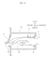
- FIG. 4 is for illustrating mask positions and a mask moving mechanism in a screen printing apparatus according to one embodiment of the present disclosure
- FIG. 5A is for illustrating a mask exchange step in a screen printing apparatus according to one embodiment of the present disclosure
- FIG. 5B is for illustrating a mask exchange step in a screen printing apparatus according to one embodiment of the present disclosure
- FIG. 5C is for illustrating a mask exchange step in a screen printing apparatus according to one embodiment of the present disclosure
- FIG. 5D is for illustrating a mask exchange step in a screen printing apparatus according to one embodiment of the present disclosure
- FIG. 5E is for illustrating a mask exchange step in a screen printing apparatus according to one embodiment of the present disclosure
- FIG. 6A is for illustrating an insertion detector included in a screen printing apparatus according to one embodiment of the present disclosure
- FIG. 6B is for illustrating an insertion detector included in a screen printing apparatus according to one embodiment of the present disclosure
- FIG. 7A is for illustrating a step of inserting a mask through an insertion opening into a screen printing apparatus according to one embodiment of the present disclosure
- FIG. 7B is for illustrating a step of inserting a mask through an insertion opening into a screen printing apparatus according to one embodiment of the present disclosure
- FIG. 8A is for illustrating a step of inserting a mask through an insertion opening into a screen printing apparatus according to one embodiment of the present disclosure
- FIG. 8B is for illustrating a step of inserting a mask through an insertion opening into a screen printing apparatus according to one embodiment of the present disclosure
- FIG. 9A is for illustrating a step of inserting a mask through an insertion opening into a screen printing apparatus according to one embodiment of the present disclosure
- FIG. 9B is for illustrating a step of inserting a mask through an insertion opening into a screen printing apparatus according to one embodiment of the present disclosure
- FIG. 10 is for illustrating detection of insertion of a foreign object by an insertion detector included in a screen printing apparatus according to one embodiment of the present disclosure
- FIG. 11A is for illustrating components of an insertion detector included in a screen printing apparatus according to one embodiment of the present disclosure
- FIG. 11B is for illustrating components of an insertion detector included in a screen printing apparatus according to one embodiment of the present disclosure
- FIG. 12 is a block diagram illustrating a control system of a screen printing apparatus according to one embodiment of the present disclosure.
- FIG. 13 is a flow chart illustrating a sequence of control steps performed when an object is inserted through an insertion opening into a screen printing apparatus according to one embodiment of the present disclosure.
- a line along which the substrate is transported is defined as the X line (extending left and right in FIG. 2 )
- a line along which the mask is transported is defined as the Y line (extending left and right in FIG. 1 and up and down in FIG.
- forward refers to the direction in which the mask travels, and corresponds to the negative direction along the Y axis.
- Rearward refers to the direction opposite the direction in which the mask travels, and corresponds to the positive direction along the Y axis.
- Left refers to left from the front looking rearward, and corresponds to the negative direction along the X axis.
- Light refers to right from the perspective of the direction in which the mask travels, and corresponds to the positive direction along the X axis.
- screen printing apparatus 1 is an apparatus that prints paste, such as solder paste, onto substrate 4 through mask M including frame 3 and screen 2 which has holes 2 h and is stretched across frame 3 .
- Screen printing apparatus 1 includes substrate retaining and moving unit 5 , squeegee unit 6 , camera unit 7 , and a paste feed apparatus (not illustrated in the drawings).
- front frame component 3 F the component of frame 3 in the front along the Y line
- back frame component 3 B the component of frame 3 on the right along the X line
- right frame component 3 R the component of frame 3 on the left along the X line
- left frame component 3 L the component of frame 3 on the left along the X line
- Substrate retaining and moving unit 5 is disposed above base 8 , and retains and moves substrate 4 .
- Right frame component 3 R and left frame component 3 L are supported from below by pair of mask guides 9 that extend parallel to the Y line, and mask M is held horizontally at a predetermined position in screen printing apparatus 1
- Mask M is used for printing paste onto substrate 4 retained by substrate retaining and moving unit 5 .
- Mask M is retained at printing position Pp at which paste is printed on substrate 4 above substrate retaining and moving unit 5 .
- Squeegee unit 6 is disposed above mask M.
- Camera unit 7 is disposed below mask M.
- the paste feed apparatus is integral with squeegee unit 6 , and feeds paste onto screen 2 of mask M retained at printing position Pp.
- substrate retaining and moving unit 5 includes, on base 8 , in order from the bottom to the top, XY ⁇ moving mechanism 11 , base table 12 , first elevation table 13 , and second elevation table 14 .
- Base table 12 moves in a horizontal plane and rotates ⁇ degrees about the Z axis via XY ⁇ moving mechanism 11 .
- First elevation table 13 moves up and down relative to base table 12 via first elevation table elevation motor 13 m .
- Second elevation table 14 moves up and down relative to first elevation table 13 via second elevation table elevation motor 14 m.
- Pair of conveyor support components 15 that extend upward through second elevation table 14 are provided above first elevation table 13 .
- Pair of conveyor support components 15 support pair of transport conveyors 16 that extend parallel to the X line and are aligned along the Y line.
- Pair of transport conveyors 16 support two ends of substrate 4 from below and transport substrate 4 along the X line.
- Lower support component 17 is provided on the top surface of second elevation table 14 .
- a pair of clamp components (clamps 18 ) are provided above pair of transport conveyors 16 , extend parallel to the X line, and are aligned along the Y line. Pair of clamps 18 open and close along the Y line via actuation by clamp actuating cylinder 18 s , and sandwich and retain (clamp) two ends of substrate 4 supported by lower support component 17 .
- holes 2 h that correspond to electrodes 4 a of substrate 4 are formed in screen 2 of mask M.
- a group of mask marks 2 m are marked on screen 2 .
- the group of mask marks 2 corresponds to a group of substrate marks 4 m marked at diagonally opposing positions on substrate 4 .
- squeegee unit 6 includes two squeegees 22 aligned along the Y line below squeegee base 21 extending parallel to the X line.
- Squeegee base 21 is moved along the Y line by squeegee unit moving mechanism 23 .
- the two squeegees 22 are moved up and down individually relative to squeegee base 21 by squeegee elevation cylinder 24 disposed on squeegee base 21 .
- camera unit 7 includes upward imaging camera 31 pointed upward so as to have an upward imaging field of view, and downward imaging camera 32 pointed downward so as to have a downward imaging field of view.
- Camera unit 7 is moved in the horizontal plane by camera unit moving mechanism 33 .
- Horizontal positioning of substrate 4 relative to mask M at printing position Pp is performed by inserting camera unit 7 between substrate 4 and mask M, imaging mask marks 2 m using upward imaging camera 31 , imaging substrate marks 4 m using downward imaging camera 32 , and performing the positioning based on the imaging results.
- FIG. 2 rearward of printing position Pp along the Y line is waiting position Pw at which a replacement mask M to be inserted through insertion opening 41 provided in the rear surface of screen printing apparatus 1 is kept on standby. Forward of the printing position Pp along the Y line is exit position Pe for moving the used mask M and removing the used mask M from the apparatus.
- Pair of mask guides 9 extend parallel to the Y line, and include waiting position Pw, printing position Pp, and exit position Pe.
- Mask M inserted through insertion opening 41 moves forward along the Y line, on pair of mask guides 9 , from waiting position Pw to printing position Pp and then to exit position Pe.
- Insertion detector 40 (to be described later) is provided protruding rearward from side wall 1 b on the rear side of enclosure 1 a . Insertion opening 41 into which a replacement mask M is inserted is formed on the rear surface of insertion detector 40 . Entrance and exit openings 42 through which substrate 4 is transported onto and off of pair of transport conveyors 16 are formed on left and right side walls 1 c and 1 d of enclosure 1 a.
- mask moving mechanism 50 included in screen printing apparatus 1 When changing the type of substrate 4 to be printed with paste, mask M is exchanged with mask M corresponding to the new substrate 4 . This is also known as making set-up change. In screen printing apparatus 1 according to this embodiment, mask moving mechanism 50 automatically exchanges masks M upon a set-up change.
- Mask moving mechanism 50 includes, at the lower end thereof, abutting component 51 that abuts frame 3 of mask M and moves mask M.
- Mask moving mechanism 50 includes cylinder 52 that raises and lowers abutting component 51 (arrow a).
- Mask moving mechanism 50 further includes an anteroposterior movement mechanism (omitted from the drawings) that moves abutting component 51 and cylinder 52 forward and backward along the Y line (arrow b). Note that the anteroposterior movement mechanism may also function as squeegee unit moving mechanism 23 that moves squeegee base 21 forward and backward along the Y line.
- Mask moving mechanism 50 is controlled by exchange processing unit 63 (see FIG. 12 ) included in control apparatus 60 .
- mask M that is inserted through insertion opening 41 and positioned at waiting position Pw is automatically moved to printing position Pp by mask moving mechanism 50 controlled by exchange processing unit 63 .
- mask M positioned at printing position Pp is automatically moved to exit position Pe by mask moving mechanism 50 controlled by exchange processing unit 63 .
- Mask M moved to exit position Pe is removed after the operator upwardly opens (arrow c) cover 1 e located on the top-front portion of enclosure 1 a covering and protecting mask M.
- exchange processing unit 63 Upon making a set-up change, the exchanging of masks M is automatically performed under control by exchange processing unit 63 .
- used mask M( 1 ) is positioned at printing position Pp
- replacement mask M( 2 ) is positioned at waiting position Pw.
- exchange processing unit 63 first positions abutting component 51 of mask moving mechanism 50 behind front frame component 3 F of replacement mask M( 2 ), and lowers (arrow d 1 ) abutting component 51 to a predetermined height at which abutting component 51 will catch on front frame component 3 F.
- exchange processing unit 63 then moves abutting component 51 forward (arrow d 2 ). With this, front frame component 3 F of replacement mask M( 2 ) pushes back frame component 3 B of used mask M( 1 ) whereby used mask M( 1 ) and replacement mask M( 2 ) move forward along pair of mask guides 9 .
- exchange processing unit 63 then raises abutting component 51 to a predetermined height at which abutting component 51 will not catch on frame 3 , and moves abutting component 51 behind back frame component 3 B of replacement mask M( 2 ) while maintaining this height (arrow d 3 ).
- exchange processing unit 63 then lowers abutting component 51 to a height at which abutting component 51 will catch on back frame component 3 B, and moves abutting component 51 forward (arrow d 4 ) until used mask M( 1 ) is positioned at exit position Pe. In this state, replacement mask M( 2 ) is positioned forward of printing position Pp.
- exchange processing unit 63 then raises abutting component 51 to a height at which abutting component 51 will not catch on frame 3 , and moves abutting component 51 in front of back frame component 3 B of replacement mask M( 2 ) while maintaining this height.
- Exchange processing unit 63 then lowers abutting component 51 to a height at which abutting component 51 will catch on back frame component 3 B, and moves abutting component 51 rearward (arrow d 5 ) until replacement mask M( 2 ) reaches printing position Pp. This completes the moving of used mask M( 1 ) to exit position Pe and the moving of replacement mask M( 2 ) to printing position Pp.
- FIG. 6A illustrates a cross section of insertion detector 40 taken at line EE in FIG. 2 .
- FIG. 6B is a simplified illustration of insertion detector 40 when viewed from the back of screen printing apparatus 1 , i.e., when viewed from the insertion opening 41 side.
- insertion opening 41 having width W 1 and height H 1 is formed in the rear surface of chassis 40 a of insertion detector 40 .
- Width W 1 and height H 1 are set so as to be larger than the width and height of mask M, respectively, when mask M is laid horizontally flat. With this, while laid horizontally flat, mask M can be inserted into screen printing apparatus 1 through insertion opening 41 and positioned at waiting position Pw via insertion detector 40 .
- first shutter 43 is provided at insertion opening 41 .
- the top portion of first shutter 43 is connected to chassis 40 a of insertion detector 40 by first hinge 44 , which allows first shutter 43 to swing (arrow f 1 ) inward into (toward the front of) screen printing apparatus 1 .
- First shutter 43 covers insertion opening 41 while suspended vertically when no force is applied (the closed state illustrated by the solid lines in FIG. 6A ).
- first shutter 43 swings inward (forward) and upward (to the open state illustrated by the dashed lines in FIG. 6A ).
- first shutter 43 swings forward so as to change from a closed state to an open state (see FIG. 7B ).
- First sensor 45 such as a proximity sensor that detects the opening and closing of first shutter 43 , is disposed on the bottom end portion of first shutter 43 and across from the bottom end portion of first shutter 43 on chassis 40 a of insertion detector 40 .
- the detection result from first sensor 45 is transmitted to control apparatus 60 (see FIG. 12 ).
- first sensor 45 is not limited to the example illustrated in FIG. 6A ; first sensor 45 may be any device capable of detecting whether first shutter 43 is in an open state or in a closed state.
- first shutter 43 that swings forward when pushed by the front component of frame 3 (front frame component 3 F) of mask M when mask M is inserted, and first sensor 45 that detects first shutter 43 swinging forward are provided at insertion opening 41 (first detection position) through which mask M is inserted to waiting position Pw, and are a first detecting unit for detecting the presence or absence of the front component of frame 3 (front frame component 3 F) of mask M, which is inserted through insertion opening 41 , at the first detection position.
- the first detecting unit merely detects, at the first detection position, front frame component 3 F (back frame component 3 B) of mask M inserted through insertion opening 41 .
- the first detecting unit may be configured as a height sensor that detects the height of front frame component 3 F (back frame component 3 B).
- lower gap 41 a having height 112 is present between the bottom of first shutter 43 and chassis 40 a of insertion detector 40 .
- Height H 2 is set to a value greater than the thickness of screen 2 of mask M.
- Right gap 41 b having width W 2 is present between the right side of first shutter 43 and chassis 40 a of insertion detector 40
- left gap 41 c having width W 3 is present between the left side of first shutter 43 and chassis 40 a of insertion detector 40 .
- Width W 2 is set to a value greater than the width of right frame component 3 R of mask M
- width W 3 is set to a value greater than the width of left frame component 3 L of mask M.
- the size and shape of first shutter 43 are set such that height 112 , width W 2 , and width W 3 fulfill the above conditions.
- first shutter 43 is closed and does not interfere with screen 2 , right frame component 3 R, or left frame component 3 L of mask M.
- first shutter 43 is of a size and a shape that does not interfere with left or right frame components 3 (right frame component 3 R or left frame component 3 L) or screen 2 of mask M when mask M is inserted.
- the first detecting unit detects objects greater than or equal to a predetermined height at the first detection position.
- the predetermined height is less than the height of frame 3 and greater than the height of screen 2 .
- the first detection position is not limited to the position of insertion opening 41 .
- the first detection position may be a position on the path between insertion opening 41 and printing position Pp along which mask M moves, and may be a position located closer to insertion opening 41 than a second detection position is (i.e., farther from printing position Pp; the second detection position will be described later).
- the first detection position is a position that front frame component 3 F and back frame component 3 B pass and right frame component 3 R or left frame component 3 L do not pass.
- middle opening 46 having width W 1 and height H 1 is formed at a position distance D away from insertion opening 41 toward the inside (front) of screen printing apparatus 1 .
- Second shutter 47 is provided at middle opening 46 .
- the top portion of second shutter 47 is connected to chassis 40 a of insertion detector 40 by second hinge 48 , which allows second shutter 47 to swing (arrow f 2 ) inward into (toward the front of) screen printing apparatus 1 , similar to first shutter 43 .
- Second sensor 49 such as a proximity sensor that detects the opening and closing of second shutter 47 , similar to first sensor 45 , is positioned at the bottom end portion of second shutter 47 and at a position on chassis 40 a of insertion detector 40 that is across from the bottom end portion of second shutter 47 . The detection result from second sensor 49 is transmitted to control apparatus 60 (see FIG. 12 ).
- second shutter 47 that swings forward when pushed by the front component of frame 3 (front frame component 3 F) of mask M when mask M is inserted, and second sensor 49 that detects second shutter 47 swinging forward are provided on the printing position Pp side (i.e., in front) of the first detecting unit (first shutter 43 and first sensor 45 ) (i.e., provided at the second detection position), and are a second detecting unit for detecting the presence or absence of the front component of frame 3 (front frame component 3 F) of mask M, which is inserted through insertion opening 41 and pushed inward, at the second detection position.
- lower gap 46 a is present between the bottom of second shutter 47 and chassis 40 a of insertion detector 40 , so as to prevent second shutter 47 and screen 2 of mask M from interfering with each other.
- right gap 46 b and left gap 46 c are present between the right and left sides, respectively, of second shutter 47 and chassis 40 a of insertion detector 40 , so as to prevent second shutter 47 and right frame component 3 R and left frame component 3 L of mask M from interfering with each other.
- second shutter 47 is of a size and shape that does not interfere with left or right frame components 3 (right frame component 3 R or left frame component 3 L) or screen 2 of mask M when mask M is inserted.
- the second detecting unit detects objects greater than or equal to a predetermined height at second detection position.
- the second detection position is a position on the path between insertion opening 41 and printing position Pp along which mask M moves, and is positioned farther from insertion opening 41 than the first detection position is (i.e., closer to printing position Pp).
- the second detection position is a position that front frame component 3 F and back frame component 3 B pass and right frame component 3 R or left frame component 3 L do not pass.
- first hinge 44 and second hinge 48 are structured so as to not allow first shutter 43 and second shutter 47 to swing rearward (outward).
- first hinge 44 is a first rear stop that inhibits first shutter 43 from swinging rearward
- second hinge 48 is a second rear stop that inhibits second shutter 47 from swinging rearward.
- the first detecting unit includes a first rear stop that inhibits first shutter 43 from swinging rearward
- the second detecting unit second includes a second rear stop that inhibits second shutter 47 from swinging rearward.
- a stop or stops other than first hinge 44 and second hinge 48 that restrict the rearward (outward) swinging of first shutter 43 and second shutter 47 may be provided as the first rear stop and/or the second rear stop.
- mask insertion steps for inserting replacement mask M through insertion opening 41 will be described with reference to FIG. 7A through FIG. 9B .
- the mask insertion steps are performed by an operator before a set-up change.
- the mask insertion steps need not be synchronized with the set-up change; printing may be performed continuously at the same time as the mask insertion steps are being performed.
- first sensor 45 and second sensor 49 are monitored by print suspension controller 62 (see FIG. 12 ) included in control apparatus 60 .
- print suspension controller 62 see FIG. 12
- the monitoring determines whether that something is mask M or a foreign object other than mask M.
- the monitoring will be described along with the mask insertion steps.
- FIG. 7A an operator is moving mask M forward from the rear, toward insertion opening 41 of insertion detector 40 (arrow g 1 ).
- first sensor 45 detects a closed first shutter 43
- second sensor 49 detects a closed second shutter 47 .
- FIG. 7B an operator moves mask M farther forward (inward) (arrow g 2 ) whereby first shutter 43 is lifted upward and forward (arrow g 3 ) by the front surface of front frame component 3 F of mask M.
- first sensor 45 detects an open first shutter 43 .
- FIG. 8A an operator moves mask M farther forward (arrow g 4 ) such that front frame component 3 F passes the first detecting unit (first shutter 43 ) and first shutter 43 closes (arrow g 5 ). As a result, first sensor 45 detects a closed first shutter 43 .
- FIG. 8B an operator moves mask M farther forward (arrow g 6 ) whereby second shutter 47 is lifted upward and forward (arrow g 7 ) by the front surface of front frame component 3 F of mask M. As a result, second sensor 49 detects an open second shutter 47 .
- FIG. 9A an operator moves mask M farther forward (arrow g 8 ) such that front frame component 3 F passes the second detecting unit (second shutter 47 ) and second shutter 47 closes (arrow g 9 ).
- second sensor 49 detects a closed second shutter 47 .
- FIG. 9B an operator moves mask M farther forward (arrow g 10 ) whereby first shutter 43 is lifted upward and forward (arrow g 11 ) by the front surface of back frame component 3 B of mask M.
- first sensor 45 detects an open first shutter 43 .
- first sensor 45 detects a closed state.
- second sensor 49 detects an open state.
- second sensor 49 detects a closed state.
- print suspension controller 62 determines that some object has been inserted through insertion opening 41 . Subsequently, when there is a change in states from the first detecting unit detecting a closed state (see FIG. 8A ; second detecting unit is detecting a closed state) to only the second detecting unit detecting an open state (see FIG. 8B ; first detecting unit is detecting a closed state), print suspension controller 62 determines that the inserted object is mask M. In this case, print suspension controller 62 does not suspend but rather continues the printing.
- first shutter 43 opens whereby first sensor 45 detects an open first shutter 43 .
- second sensor 49 detects an open second shutter 47 .
- print suspension controller 62 determines that a foreign object—which is an object other than mask M, such as hand Ha of an operator—has been inserted into the apparatus through insertion opening 41 . In this case, print suspension controller 62 suspends the printing.
- insertion detector 140 and insertion opening 141 are exemplified as corresponding to insertion detector 40 and insertion opening 41 , respectively, and in FIG. 11B , insertion detector 40 and insertion opening 41 are exemplified as corresponding to insertion detector 240 and insertion opening 241 , respectively.
- FIG. 11A illustrates an example in which inserted front frame component 3 F is simultaneously detected as present by the first detecting unit and the second detecting unit due to distance D 1 being too short, whereby the insertion of mask M is erroneously determined to be an insertion of a foreign object.
- distance D between the first detecting unit (first shutter 143 ) and the second detecting unit (second shutter 147 ) needs to be set so as to prevent the front component of frame 3 (front frame component 3 F) or the back component of frame 3 (back frame component 3 B) of mask M located between the first detecting unit and the second detecting unit from being simultaneously detected by the first detecting unit (first sensor 145 ) and the second detecting unit (second sensor 149 ).
- FIG. 11B illustrates an example in which distance D 2 is set such that back frame component 3 B reaches the first detecting unit while the second detecting unit is detecting front frame component 3 F.
- the first detecting unit and the second detecting unit simultaneously detect open states, the insertion of mask M is erroneously detected as insertion of a foreign object.
- distance D between the first detecting unit (first shutter 243 ) and the second detecting unit (second shutter 247 ) needs to be set so as to prevent the front component of frame 3 (front frame component 3 F) and the back component of frame 3 (back frame component 3 B) of mask M located between the first detecting unit and the second detecting unit from being simultaneously detected by the first detecting unit (first sensor 245 ) and the second detecting unit (second sensor 249 ).
- Screen printing apparatus 1 includes control apparatus 60 .
- Control apparatus 60 controls the transporting of substrate 4 along the X line by transport conveyers 16 included in substrate retaining and moving unit 5 and the raising and lowering of lower support component 17 by second elevation table elevation motor 14 m .
- Control apparatus 60 additionally controls the clamping of substrates via clamp 18 by clamp actuating cylinder 18 s , the moving of substrate 4 in a horizontal plane by XY ⁇ moving mechanism 11 , and the raising and lowering of first elevation table 13 by first elevation table elevation motor 13 m.
- Control apparatus 60 additionally controls the moving of squeegee unit 6 along the Y line by squeegee unit moving mechanism 23 and the raising and lowering of squeegees 22 by squeegee elevation cylinder 24 .
- Control apparatus 60 additionally controls the moving of camera unit 7 in a horizontal plane by camera unit moving mechanism 33 , the imaging by upward imaging camera 31 and downward imaging camera 32 included in camera unit 7 .
- Control apparatus 60 includes, as internal processing units, image recognition unit 61 , print suspension controller 62 , and exchange processing unit 63 .
- Image recognition unit 61 performs image recognition on image data obtained by imaging by upward imaging camera 31 and downward imaging camera 32 and input into control apparatus 60 .
- Print suspension controller 62 monitors detection signals indicating open and closed states from first sensor 45 and second sensor 49 , and monitors the insertion of mask M or a foreign object other than mask M through insertion opening 41 . When first sensor 45 and second sensor 49 simultaneously detect open states, print suspension controller 62 determines that a foreign object has been inserted and suspends printing.
- print suspension controller 62 performs monitoring including determining whether something has been inserted through insertion opening 41 from the detection results from first sensor 45 and second sensor 49 , and when print suspension controller 62 determines that something has been inserted, determining whether that thing is mask M or a foreign object that is not mask M.
- Print suspension controller 62 suspends printing when print suspension controller 62 detects an insertion of a foreign object—that is to say, when the second detecting unit (second shutter 47 and second sensor 49 ) detects an insertion while the first detecting unit (first shutter 43 and first sensor 45 ) is detecting an insertion.
- Print suspension controller 62 performs the detection of the presence or absence of front frame component 3 F or back frame component 3 B of mask M at first detection position positioned at insertion opening 41 (first detection step; step ST 1 ).
- first detection position is not limited to the position of insertion opening 41 .
- the first detection position may be a position on the path between insertion opening 41 and printing position Pp along which mask M moves, and may be a position located closer to insertion opening 41 than the second detection position is (i.e., farther from printing position Pp).
- Print suspension controller 62 then performs the detection of the presence or absence of the front frame component ( 3 F) or the back frame component ( 3 B) of mask M at the second detection position which is farther from insertion opening 41 than the first detection position is (i.e., is closer to printing position Pp) (second detection step; step ST 2 ). Print suspension controller 62 suspends printing when a detection result is presence in the second detection step while a detection result is presence in the first detection step (step ST 3 ).
- Exchange processing unit 63 performs the exchanging of masks M by causing mask moving mechanism 50 to move used mask M positioned at printing position Pp to exit position Pe, and move replacement mask M on standby at waiting position Pw to printing position Pp.
- a predetermined input related to the screen printing process performed by screen printing apparatus 1 is made on input unit 64 that connects to control apparatus 60 .
- Screen printing apparatus 1 includes a first detecting unit that is provided at insertion opening 41 through which mask M is inserted and detects the front component of frame 3 (front frame component 3 F) of mask M inserted through insertion opening 41 , and a second detecting unit that is provided in front of the first detecting unit and detects the front component of frame 3 of mask M inserted through insertion opening 41 and pushed inside.
- first detecting unit that is provided at insertion opening 41 through which mask M is inserted and detects the front component of frame 3 (front frame component 3 F) of mask M inserted through insertion opening 41
- a second detecting unit that is provided in front of the first detecting unit and detects the front component of frame 3 of mask M inserted through insertion opening 41 and pushed inside.
- a screen printing apparatus is effective in that masks can be productively and safely exchanged, and is applicable in fields in which components are mounted on substrates.
Landscapes
- Engineering & Computer Science (AREA)
- Mechanical Engineering (AREA)
- Screen Printers (AREA)
- Electric Connection Of Electric Components To Printed Circuits (AREA)
- Printing Methods (AREA)
Applications Claiming Priority (2)
| Application Number | Priority Date | Filing Date | Title |
|---|---|---|---|
| JP2016-174221 | 2016-09-07 | ||
| JP2016174221A JP6467595B2 (ja) | 2016-09-07 | 2016-09-07 | スクリーン印刷装置 |
Publications (2)
| Publication Number | Publication Date |
|---|---|
| US20180065357A1 US20180065357A1 (en) | 2018-03-08 |
| US10086600B2 true US10086600B2 (en) | 2018-10-02 |
Family
ID=61282378
Family Applications (1)
| Application Number | Title | Priority Date | Filing Date |
|---|---|---|---|
| US15/643,220 Active US10086600B2 (en) | 2016-09-07 | 2017-07-06 | Screen printing apparatus and screen printing method |
Country Status (3)
| Country | Link |
|---|---|
| US (1) | US10086600B2 (ja) |
| JP (1) | JP6467595B2 (ja) |
| CN (1) | CN107791663B (ja) |
Cited By (1)
| Publication number | Priority date | Publication date | Assignee | Title |
|---|---|---|---|---|
| US20180229495A1 (en) * | 2017-02-14 | 2018-08-16 | Panasonic Intellectual Property Management Co., Ltd. | Screen printing apparatus and screen printing method |
Families Citing this family (6)
| Publication number | Priority date | Publication date | Assignee | Title |
|---|---|---|---|---|
| CN109982854B (zh) * | 2016-12-05 | 2021-09-21 | 株式会社富士 | 印刷装置 |
| US11203198B2 (en) * | 2016-12-05 | 2021-12-21 | Fuji Corporation | Printing apparatus and accommodation apparatus |
| JP6976905B2 (ja) * | 2018-06-05 | 2021-12-08 | ヤマハ発動機株式会社 | 印刷装置および印刷装置の印刷方法 |
| CN112004681B (zh) * | 2018-06-05 | 2022-01-04 | 雅马哈发动机株式会社 | 印刷装置 |
| EP4329452A4 (en) | 2021-04-23 | 2024-05-29 | Fuji Corp | MOUNTING SYSTEM |
| CN115447262B (zh) * | 2022-10-17 | 2023-10-27 | 杭州临安柏盛印刷技术有限公司 | 一种丝网印刷装置以及丝网印刷方法 |
Citations (7)
| Publication number | Priority date | Publication date | Assignee | Title |
|---|---|---|---|---|
| JP2861332B2 (ja) | 1990-08-28 | 1999-02-24 | 松下電器産業株式会社 | スクリーン印刷装置 |
| US5906158A (en) * | 1996-10-31 | 1999-05-25 | Sakurai Graphic Systems Corporation | Screen printing apparatus and method |
| US5970867A (en) * | 1996-07-26 | 1999-10-26 | Aisa S.P.A. | Machine for the silk-screen printing of sheets, equipped with apparatus for adjusting the relative position of the sheet and the printing screen |
| US20130192481A1 (en) * | 2010-10-19 | 2013-08-01 | Panasonic Corporation | Screen printing device and screen printing method |
| US20140116275A1 (en) * | 2012-11-01 | 2014-05-01 | Casey E. Walker | Reduction of print head temperature by disrupting air from heated webs of print media |
| US9044929B2 (en) * | 2011-05-13 | 2015-06-02 | Yamaha Hatsudoki Kabushiki Kaisha | Printing apparatus |
| US9398696B2 (en) * | 2011-05-31 | 2016-07-19 | Yamaha Hatsudoki Kabushiki Kaisha | Screen printing machine |
Family Cites Families (10)
| Publication number | Priority date | Publication date | Assignee | Title |
|---|---|---|---|---|
| JP2666368B2 (ja) * | 1988-05-25 | 1997-10-22 | 松下電器産業株式会社 | スクリーン印刷機 |
| JPH0643662A (ja) * | 1991-04-18 | 1994-02-18 | Pilot Corp:The | 電子回路用基板に対する露光方法と、その装置 |
| JPH06164125A (ja) * | 1992-11-19 | 1994-06-10 | Fujitsu Ltd | 不活性ガス雰囲気半田付け機のシャッタ |
| JPH09300582A (ja) * | 1996-05-15 | 1997-11-25 | Matsushita Electric Ind Co Ltd | スクリーン交換方法 |
| JP4508085B2 (ja) * | 2005-11-11 | 2010-07-21 | パナソニック株式会社 | 電子部品の実装用装置 |
| US8733245B2 (en) * | 2010-02-09 | 2014-05-27 | Samsung Techwin Co., Ltd. | Screen printer |
| JP4889133B1 (ja) * | 2011-05-10 | 2012-03-07 | 智雄 松下 | スクリーンマスクのプリセット装置およびスクリーン印刷方法 |
| JP2013141752A (ja) * | 2012-01-10 | 2013-07-22 | Panasonic Corp | スクリーン印刷装置およびスクリーン印刷方法 |
| JP6337538B2 (ja) * | 2014-03-18 | 2018-06-06 | セイコーエプソン株式会社 | 画像記録装置、キャリブレーション方法および画像記録方法 |
| CN104553235B (zh) * | 2015-01-12 | 2016-06-15 | 深圳清溢光电股份有限公司 | 贴膜机 |
-
2016
- 2016-09-07 JP JP2016174221A patent/JP6467595B2/ja active Active
-
2017
- 2017-07-06 US US15/643,220 patent/US10086600B2/en active Active
- 2017-07-18 CN CN201710588173.3A patent/CN107791663B/zh active Active
Patent Citations (7)
| Publication number | Priority date | Publication date | Assignee | Title |
|---|---|---|---|---|
| JP2861332B2 (ja) | 1990-08-28 | 1999-02-24 | 松下電器産業株式会社 | スクリーン印刷装置 |
| US5970867A (en) * | 1996-07-26 | 1999-10-26 | Aisa S.P.A. | Machine for the silk-screen printing of sheets, equipped with apparatus for adjusting the relative position of the sheet and the printing screen |
| US5906158A (en) * | 1996-10-31 | 1999-05-25 | Sakurai Graphic Systems Corporation | Screen printing apparatus and method |
| US20130192481A1 (en) * | 2010-10-19 | 2013-08-01 | Panasonic Corporation | Screen printing device and screen printing method |
| US9044929B2 (en) * | 2011-05-13 | 2015-06-02 | Yamaha Hatsudoki Kabushiki Kaisha | Printing apparatus |
| US9398696B2 (en) * | 2011-05-31 | 2016-07-19 | Yamaha Hatsudoki Kabushiki Kaisha | Screen printing machine |
| US20140116275A1 (en) * | 2012-11-01 | 2014-05-01 | Casey E. Walker | Reduction of print head temperature by disrupting air from heated webs of print media |
Cited By (2)
| Publication number | Priority date | Publication date | Assignee | Title |
|---|---|---|---|---|
| US20180229495A1 (en) * | 2017-02-14 | 2018-08-16 | Panasonic Intellectual Property Management Co., Ltd. | Screen printing apparatus and screen printing method |
| US10688779B2 (en) * | 2017-02-14 | 2020-06-23 | Panasonic Intellectual Property Management Co., Ltd. | Screen printing apparatus and screen printing method |
Also Published As
| Publication number | Publication date |
|---|---|
| CN107791663A (zh) | 2018-03-13 |
| US20180065357A1 (en) | 2018-03-08 |
| JP2018039173A (ja) | 2018-03-15 |
| JP6467595B2 (ja) | 2019-02-13 |
| CN107791663B (zh) | 2021-05-14 |
Similar Documents
| Publication | Publication Date | Title |
|---|---|---|
| US10086600B2 (en) | Screen printing apparatus and screen printing method | |
| KR102383305B1 (ko) | 수납 장치 및 인쇄 시스템 | |
| JP4831061B2 (ja) | 電子部品実装用装置および電子部品実装用装置の非常停止方法 | |
| JP4968282B2 (ja) | 部品実装装置 | |
| CN107432111A (zh) | 元件供给装置 | |
| JP7022887B2 (ja) | 部品実装装置、ノズル交換台設置方法及びノズル交換台取出し方法 | |
| JP6590709B2 (ja) | 部品実装装置および部品実装方法 | |
| JP2009295758A (ja) | 電子部品実装装置 | |
| CN106471878A (zh) | 检测装置 | |
| JP6596649B2 (ja) | トレイフィーダ及び部品実装装置 | |
| JP2015173192A (ja) | 部品実装装置における吸着ノズルの交換方法、部品実装装置及び吸着ノズル供給ユニット | |
| JP5309964B2 (ja) | 電子部品実装ライン及び電子部品実装ラインによる作業方法 | |
| JP6603616B2 (ja) | 部品実装装置、部品実装システム、段取支援方法および段取支援プログラム | |
| CN108136595B (zh) | 元件供给系统及分散元件的拾取装置 | |
| JP2010278269A (ja) | 支持ピンの移載方法 | |
| JP6678295B2 (ja) | 部品供給装置 | |
| JPWO2018193559A1 (ja) | ノズル保持機構および部品実装装置 | |
| JP5096420B2 (ja) | プリント基板の支持装置 | |
| JP6840223B2 (ja) | 部品実装装置および基板の保持方法 | |
| JP5058126B2 (ja) | 電子部品装着装置 | |
| JP6661405B2 (ja) | 部品実装装置および部品実装方法 | |
| JP2010109193A (ja) | 電子部品装着装置 | |
| JP2018041880A (ja) | 部品供給装置 | |
| JP5658707B2 (ja) | 電子部品装着装置 | |
| JP5214516B2 (ja) | 支持ピン移載装置 |
Legal Events
| Date | Code | Title | Description |
|---|---|---|---|
| AS | Assignment |
Owner name: PANASONIC INTELLECTUAL PROPERTY MANAGEMENT CO., LT Free format text: ASSIGNMENT OF ASSIGNORS INTEREST;ASSIGNORS:MANTANI, MASAYUKI;SAKAUE, TAKAAKI;SIGNING DATES FROM 20170605 TO 20170606;REEL/FRAME:043598/0431 |
|
| STCF | Information on status: patent grant |
Free format text: PATENTED CASE |
|
| MAFP | Maintenance fee payment |
Free format text: PAYMENT OF MAINTENANCE FEE, 4TH YEAR, LARGE ENTITY (ORIGINAL EVENT CODE: M1551); ENTITY STATUS OF PATENT OWNER: LARGE ENTITY Year of fee payment: 4 |