US10083783B2 - Rare earth based magnet - Google Patents
Rare earth based magnet Download PDFInfo
- Publication number
- US10083783B2 US10083783B2 US14/579,315 US201414579315A US10083783B2 US 10083783 B2 US10083783 B2 US 10083783B2 US 201414579315 A US201414579315 A US 201414579315A US 10083783 B2 US10083783 B2 US 10083783B2
- Authority
- US
- United States
- Prior art keywords
- rare earth
- crystal boundary
- atomic
- boundary phases
- phases
- Prior art date
- Legal status (The legal status is an assumption and is not a legal conclusion. Google has not performed a legal analysis and makes no representation as to the accuracy of the status listed.)
- Active, expires
Links
Images


Classifications
-
- H—ELECTRICITY
- H01—ELECTRIC ELEMENTS
- H01F—MAGNETS; INDUCTANCES; TRANSFORMERS; SELECTION OF MATERIALS FOR THEIR MAGNETIC PROPERTIES
- H01F1/00—Magnets or magnetic bodies characterised by the magnetic materials therefor; Selection of materials for their magnetic properties
- H01F1/01—Magnets or magnetic bodies characterised by the magnetic materials therefor; Selection of materials for their magnetic properties of inorganic materials
- H01F1/03—Magnets or magnetic bodies characterised by the magnetic materials therefor; Selection of materials for their magnetic properties of inorganic materials characterised by their coercivity
- H01F1/032—Magnets or magnetic bodies characterised by the magnetic materials therefor; Selection of materials for their magnetic properties of inorganic materials characterised by their coercivity of hard-magnetic materials
- H01F1/04—Magnets or magnetic bodies characterised by the magnetic materials therefor; Selection of materials for their magnetic properties of inorganic materials characterised by their coercivity of hard-magnetic materials metals or alloys
- H01F1/047—Alloys characterised by their composition
- H01F1/053—Alloys characterised by their composition containing rare earth metals
- H01F1/055—Alloys characterised by their composition containing rare earth metals and magnetic transition metals, e.g. SmCo5
- H01F1/057—Alloys characterised by their composition containing rare earth metals and magnetic transition metals, e.g. SmCo5 and IIIa elements, e.g. Nd2Fe14B
- H01F1/0571—Alloys characterised by their composition containing rare earth metals and magnetic transition metals, e.g. SmCo5 and IIIa elements, e.g. Nd2Fe14B in the form of particles, e.g. rapid quenched powders or ribbon flakes
- H01F1/0575—Alloys characterised by their composition containing rare earth metals and magnetic transition metals, e.g. SmCo5 and IIIa elements, e.g. Nd2Fe14B in the form of particles, e.g. rapid quenched powders or ribbon flakes pressed, sintered or bonded together
- H01F1/0577—Alloys characterised by their composition containing rare earth metals and magnetic transition metals, e.g. SmCo5 and IIIa elements, e.g. Nd2Fe14B in the form of particles, e.g. rapid quenched powders or ribbon flakes pressed, sintered or bonded together sintered
Definitions
- the present invention relates to a rare earth based magnet, especially a rare earth based magnet in which the microstructure of the R-T-B based sintered magnet is controlled.
- the R-T-B based sintered magnet (R represents a rare earth element, T represents at least one iron family element with Fe as essential, and B represents boron) represented by the Nd—Fe—B based sintered magnet has a high saturation magnetic flux density.
- R represents a rare earth element
- T represents at least one iron family element with Fe as essential
- B represents boron
- Nd—Fe—B based sintered magnet has a high saturation magnetic flux density.
- part of Nd in the Nd 2 Fe 14 B compound (which is the main phase) is replaced with the heavy rare earth element(s) such as Dy or Tb.
- the magneto crystalline anisotropy constant can be improved by replacing part of Nd with the heavy rare earth element(s).
- the coercivity of the Nd—Fe—B based sintered magnet at room temperature can be improved sufficiently.
- the addition of Cu or the like will also elevate the coercivity at room temperature (Patent Document 1).
- the addition of Cu will render Cu form, for example, the Nd—Cu liquid phase in the crystal boundary so that the crystal boundary will become smooth. In this way, the reverse magnetic domains can be prevented from generating.
- Patent Documents 2, 3 and 4 have disclosed a technology that the crystal boundary phase (which is the microstructure of the rare earth based magnet) is controlled to improve the coercivity.
- the crystal boundary phases refer to the crystal boundary phases surrounded by three or more main phase crystal grains and are also called the triple junction points.
- a technology has been disclosed for forming two kinds of triple junction points with different Dy concentrations. That is, it has been disclosed that crystal boundary phases (triple junction points) are formed with part areas having a high concentration of Dy and the total concentration of Dy unchanged so that a high resistance with respect to the reversal of the magnetic domain can be maintained.
- the Patent Document 3 has disclosed a technology that three kinds of crystal boundary phases (triple junction points) (the first one, second one and third one) are formed with different total atomic concentrations of rare earth elements, wherein the atomic concentration of rare earth elements in the third crystal boundary phase is lower than that in other two crystal boundary phases, and the atomic concentration of Fe in the third crystal boundary phase is higher than that in other two crystal boundary phases. In this way, a third crystal boundary phase with a high Fe concentration can be formed in the crystal boundary phases, resulting in the improvement of coercivity.
- Patent Document 4 has disclosed an R-T-B based rare earth based sintered magnet which is formed by a sintered body, and the sintered body consists of main phases (which mainly contains R 2 T 14 B) and crystal boundary phases with more R than the main phases.
- the crystal boundary phases contain phases with the total atomic concentration of rare earth elements being 70 atomic % or more and phases with the total atomic concentration of rare earth elements being 25 to 35 atomic %.
- the phases with the total atomic concentration of rare earth elements being 25 to 35 atomic % are referred to as the transition metal-rich phases, and the atomic concentration of Fe in these phases are preferably 50 to 70 atomic %. In this respect, coercivity is improved.
- Patent Document 1 JP2002-327255
- Patent Document 2 JP2012-15168
- Patent Document 3 JP2012-15169
- Patent Document 4 International Publication Pamphlet No. 2013/008756
- the value of coercivity at room temperature is one of the effective indexes.
- part of R in the R 2 T 14 B compound i.e., the main phase
- a heavy rare earth element such as Tb or Dy
- the coercivity at room temperature is evidently improved. It is an easy way to improve the coercivity, but the source of the heavy rare earth elements such as Dy and Tb may be problematic because the places of origin and outputs are limited.
- the decrease of residual flux density is unavoidable due to for example the antiferromagnetic coupling of Nd and Dy.
- the addition of Cu as described above and the like are also effective to improve the coercivity.
- the demagnetization at a high temperature is expected to be further inhibited.
- the crystal boundary phases which are the microstructure if the coercivity of the rare earth based magnets (i.e., the R-T-B based sintered magnets) is to be improved.
- the crystal boundary phases there are the so-called two-grain boundary phases formed between two adjacent main phase crystal grains and the so-called triple junction points surrounded by three or more main phase crystal grains.
- the triple junction point is simply referred to as the crystal boundary phase hereinafter in this specification.
- the coercivity at room temperature is highly improved with the replacement of heavy rare earth elements such as Dy and Tb but the magneto crystalline anisotropy constant (the main factor for the coercivity) dramatically changes as the temperature varies. That is, when the temperature becomes high in the environment where rare earth based magnets are used, the coercivity dramatically decreases.
- the inventors have found that it is important to control the microstructure as shown below to obtain a rare earth based magnet with demagnetization at a high temperature being inhibited. If the coercivity can be improved by controlling the microstructure of the sintered magnets, the obtained rare earth based magnet will have excellent temperature stability.
- the coercivity of the rare earth based magnet is to be improved, it is important to cut off the magnetic coupling among R 2 T 14 B crystal grains (which are the main phases). If the major crystal grains can be magnetically isolated, the adjacent crystal grains will not be affected even if reverse magnetic domains are generated in some certain crystal grains. In this respect, the coercivity can be improved.
- the coercivity is improved by forming several kinds of crystal boundary phases (triple junction points) with different constitutions. However, it is not clear what kind of structure of the crystal boundary phases (triple junction points) will result in sufficient magnetic isolation among main phase crystal grains. Especially in the technologies disclosed in Patent Documents 3 and 4, crystal boundary phases with a lot of Fe atoms are formed. With only such a structure, the magnetic coupling among main phase crystal grains may not be sufficiently inhibited.
- the inventors of the present invention believe that it is important to control the crystal boundary phases (triple junction points) during the formation of the two-grain boundary phases with good effect on cutting off the magnetic coupling between adjacent crystal grains.
- kinds of conventional rare earth based magnets have been studied. For example, if nonmagnetic two-grain boundary phases can be formed with a relatively high concentration of the rare earth element R by increasing the ratio of R (which is a constituent of the magnet), sufficient effect on cutting off the magnetic coupling can be expected.
- the present invention aims to significantly inhibit the demagnetization rate at a high temperature in the R-T-B based sintered magnet (i.e., the rare earth based magnet).
- the inventors of the present invention have studied the structure of the main phase crystal grains and triple junction points in the sintered body of the rare earth based magnets, wherein the triple junction points may form two-grain boundary phases which cut off the magnetic coupling between adjacent main phase crystal grains. As a result, the following invention has been completed.
- the rare earth based magnet of the present invention is a sintered magnet containing R 2 T 14 B crystal grains (which are the main phases), two-grain boundary phases between two R 2 T 14 B crystal grains, and triple junction points.
- the crystal boundary phase When the microstructure of the sintered body is observed at any section, the phase surrounded by three or more main phase crystal grains is referred to as the crystal boundary phase.
- the crystal boundary phase containing at least R-T-M with R, T and M respectively accounting for 20 to 40 atomic %, 60 to 75 atomic % and 1 to 10 atomic % is referred to as the first crystal boundary phase
- the crystal boundary phase containing at least R-T-M with R, T and M respectively accounting for 50 to 70 atomic %, 10 to 30 atomic % and 1 to 20 atomic % is referred to as the second crystal boundary phase.
- the sintered body contains at least these two kinds of crystal boundary phases. With such a composition, the absolute value of the demagnetization rate at a high temperature is inhibited to a level of 4% or less.
- M represents at least one selected from the group consisting of Al, Ge, Si, Sn and Ga.
- the ratio of the area of the first crystal boundary phase to the area of the second crystal boundary phase is 0.5 or more at the sections. With such a ratio, the absolute value of the demagnetization rate at a high temperature can be inhibited to a level of 3% or less.
- the first and second crystal boundary phases will not become ferromagnetic compounds even if T is contained therein.
- the T atom such as the Fe atom unevenly distributed in the conventional R—Cu two-grain boundary phases is consumed in the forms of the first and second crystal boundary phases.
- the concentration of iron family element(s) in the phases can be lowered extremely, and the two-grain boundary phase becomes a non-ferromagnetic phase.
- the second crystal boundary phase takes up and consumes less T atoms such as Fe atoms than the first crystal boundary phase as it has a lower concentration of T than the first crystal boundary phase.
- the concentration of T in the two-grain boundary phases can be effectively decreased by properly forming the first crystal boundary phases which take up and consume more T atoms.
- M is contained in the sintered body.
- the first crystal boundary phases and the second crystal boundary phases containing R-T-M can be formed in the sintered body by adding the rare earth element R and iron family element T (which are the constituents of the main phase crystal grains) and element M (which forms the ternary eutectic point with R and T).
- R and T which are the constituents of the main phase crystal grains
- element M which forms the ternary eutectic point with R and T.
- the concentration of T in the two-grain boundary phases can be lowered.
- the addition of M promotes the generation of the R-T-M-containing crystal boundary phase, and the element T present in the two-grain boundary phases is consumed during the generation of the crystal boundary phase, which may be the reason why the concentration of T is decreased in the two-grain boundary phases.
- the crystal boundary phases containing R-T-M are considered as compounds, and these crystal boundary phases become non-ferromagnetic crystal boundary phases although Fe is contained.
- the crystal boundary phases consisting of R-T-M based compounds are analyzed via the electron microscopy and the electron holography, it can be known that the crystal boundary phases become non-ferromagnetic phases which are presumed to be antiferromagnetic or ferrimagnetic with a quite low magnetization value although Fe is contained therein.
- the iron family element T is contained as a constituent of the compound and non-ferromagnetic crystal boundary phases are formed even if the iron family elements such as Fe and Co are contained, it is believed that the nucleation of the reverse magnetic domains can be prevented.
- the element M which promotes the reaction together with R and T (which two elements constitute the main phase crystal grains mentioned above)
- Al, Ga, Si, Ge, Sn and the like can be used as the element M which promotes the reaction together with R and T.
- a rare earth based magnet with a small demagnetization rate at a high temperature can be provided as well as a rare earth based magnet applicable to motors used under high temperature environments.
- FIG. 1 is an electron micrograph showing the crystal boundary phases of the rare earth based magnet of Example 4 according to an embodiment of the present invention.
- FIG. 2 is an electron micrograph showing the crystal boundary phases of the rare earth based magnet of Comparative Example 2 of the present embodiment.
- FIGS. 3A and 3B are graphs showing the two-grain boundary phase of the rare earth based magnet in Comparative Example 2 of the present embodiment.
- FIGS. 4A and 4B are graphs showing the two-grain boundary phase of the rare earth based magnet according to the present embodiment of the present invention.
- the rare earth based magnet of the present invention is a sintered magnet comprising main phase crystal grains of R 2 T 14 B, two-grain boundary phases and crystal boundary phases (triple junction points), wherein R contains one or more rare earth elements, T contains one or more iron family elements with Fe as essential, and B represents boron.
- R contains one or more rare earth elements
- T contains one or more iron family elements with Fe as essential
- B represents boron.
- various well known additive elements are added and inevitable impurities are contained.
- FIG. 1 is an electron micrograph showing the structure at a section of the rare earth based magnet in an embodiment of the present invention.
- the rare earth based magnet of the present embodiment comprises the main phase crystal grains 1 (which are mainly composed of R 2 T 14 B), the two-grain boundary phases 2 formed between two adjacent main phase crystal grains 1, and the crystal boundary phases 3 surrounded by three or more main phase crystal grains.
- the rare earth based magnet contains at least these two kinds of crystal boundary phases.
- the rare earth element R can be any one of the light rare earth element, the heavy rare earth element or their combination.
- Nd or Pr or their combination is preferable.
- the other elements are as mentioned above. The preferable range for the combination of Nd and Pr will be described below.
- the rare earth based magnet of the present embodiment may contain a trace of additive elements.
- additive element well known additive elements can be used.
- the additive elements are preferably those having a eutectic composition with R, wherein R is the constituent of the main phase crystal grains of R 2 T 14 B.
- the additive element is preferred to be Cu.
- other elements can also be used. The proper range for Cu to be added will be described below.
- the rare earth based magnet of the present embodiment may further contain Al, Ga, Si, Ge, Sn and the like as the element M which promotes the reaction in the powder metallurgical processes of the main phase crystal grains.
- the appropriate amount of M to be added will be described below. With the addition of M in the rare earth based magnet, reactions happen in the surface layer of the main phase crystal grains. Thus, the distortions and defects will be eliminated while the generation of the crystal boundary phases containing R-T-M will be promoted via the reaction between the element T existing in the two-grain boundary phases and the element M. As a result, the concentration of T is decreased in the two-grain boundary phases.
- the amount of each element relative to the total mass is as follows.
- R contained in the rare earth based magnet of the present embodiment will be more specifically described.
- R must contain either one of Nd and Pr.
- the sum of Nd and Pr may accounts for 80 to 100 atomic % or 95 to 100 atomic %. If the ratio is within such a range, good residual flux density and coercivity can be further obtained.
- the heavy rare earth element such as Dy, Tb or the like can be contained as R.
- the sum of the heavy rare earth elements accounts for 1.0 mass % or less, and preferably 0.5 mass % or less, and more preferably 0.1 mass % or less.
- the rare earth based magnet of the present embodiment even if the amount of the heavy rare earth elements is decreased, a high coercivity can still be obtained and the demagnetization rate at a high temperature can still be inhibited by rendering the amount and atomic ratio of other elements meet certain requirements.
- the amount of B is 0.7 to 0.95 mass %.
- the reaction at the surface of the main phase crystal grains will easily occur during the powder metallurgical processes in combination with the additive elements through the amount of B being less than the stoichiometric ratio of basic component R 2 T 14 B.
- the rare earth based magnet of the present embodiment further contains a trace of additive elements.
- additive elements well known additive elements can be used.
- the additive element is preferably those having a eutectic point with the element R (which is the constituent of the main phase crystal grains of R 2 T 14 B) in the phase diagram.
- Cu or the like is preferred as the additive element.
- other elements can be used.
- the amount of added Cu is 0.01 to 1.5 mass % based on the whole. If the added amount is within this range, Cu will almost unevenly distribute only in the two-grain boundary phases and the crystal boundary phases (i.e., the triple junction points).
- the element M is preferably added which will have a eutectic point in the R-T-M ternary system.
- an element M it can be Al, Ga, Si, Ge, Sn or the like.
- the amount of M is 0.03 to 1.5 mass %.
- the element T in the basic component of R 2 T 14 B has Fe as essential and may also contain other iron family elements.
- Co is preferred as the iron family element.
- the amount of Co is preferably ranges from a level above 0 mass % to a level that is under 3.0 mass %. If Co is contained in the rare earth based magnet, the curie temperature will be elevated and the corrosion resistance will be improved too. The amount of Co may also be 0.3 to 2.5 mass %.
- the rare earth based magnet of the present embodiment may also contain C as additional elements, and the amount of C is 0.05 to 0.3 mass %. If less C is contained, the coercivity will become insufficient. If more C is contained, the ratio of the value of the magnetic field (Hk) to the coercivity, i.e., the squareness ratio (Hk/coercivity) will become insufficient, where the magnetic field (Hk) is the field when the magnetization becomes 90% of the residual flux density. In order to obtain better coercivity and squareness ratio, the amount of C may also be 0.1 to 0.25 mass %.
- the rare earth based magnet of the present embodiment may also contain O as additional elements, and 0.03 to 0.4 mass % of O can be contained. If less O is contained, the corrosion resistance of the sintered magnet will not be sufficient. If more O is contained, the liquid phase will not be sufficiently formed in the sintered magnet and the coercivity will decrease. In order to obtain better corrosion resistance and coercivity, the amount of O can be 0.05 to 0.3 mass % or 0.05 to 0.25 mass %.
- the amount of N is preferably 0.15 mass % or less. If more N is contained, the coercivity tends to be insufficient.
- the sintered magnet of the present embodiment when the amount of each element falls within the ranges mentioned above and the numbers of C, O and N atoms are respectively referred to as [C], [0] and [N], [0]/([C]+[N]) ⁇ 0.60.
- the absolute value of demagnetization rate at a high temperature can be inhibited to a low level.
- the numbers of Nd, Pr, B, C and M atoms satisfy the correlations below.
- the numbers of Nd, Pr, B, C and M atoms are respectively referred to as [Nd], [Pr], [B], [C] and [M]
- a high coercivity can be maintained.
- the rare earth based magnet of the present embodiment can be prepared by a common powder metallurgical method which comprises a preparation process for preparing the alloy raw materials, a pulverization process in which fine powers are obtained by pulverizing alloy raw materials, a molding process in which the fine powders are molded to make a molded body, a sintering process in which the molded body is fired to get a sintered body, and a heat treating process in which an aging treatment is applied to the sintered body.
- the preparation process is a process in which alloy raw materials having elements contained in the rare earth based magnet of the present embodiment are prepared.
- starting metals with specified elements are prepared for the strip casting method and the like.
- the alloy raw materials are prepared.
- the starting metals can be for example the rare earth based metal or the rare earth based alloy, the pure iron, the ferro-boron, or the alloys thereof. These starting metals are used to prepare alloy raw materials from which rare earth based magnets with a desired composition can be obtained.
- fine powder raw materials are obtained by pulverizing the alloy raw materials obtained from the preparation process.
- This process is preferably performed in two stages, i.e., the coarse pulverization process and fine pulverization process. Also, this process can be done in one stage.
- the coarse pulverization process for example, the stamp mill, the jaw crusher, the braun mill and the like can be used under an inert atmosphere.
- the hydrogen decrepitation can be performed in which pulverization is performed after the hydrogen is adsorbed.
- the alloy raw materials are pulverized until a particle size of several hundreds of micrometers to several millimeters is achieved.
- the coarse powders obtained in the coarse pulverization process are finely pulverized to prepare fine powders with an average particle size of about several micrometers.
- the average particle size of the fine powders can be set depending on the growth of the sintered crystal grains.
- the fine pulverization can be performed by using for example a jet mill.
- the molding process is a process in which the fine powder raw materials are molded in a magnetic field to make a molded body. Specifically, after the fine powder raw materials are filled in a mold disposed in an electromagnet, the molding is performed by orientating the crystallographic axis of the fine powder raw materials by applying a magnetic field via the electromagnet, while pressurizing the fine powder raw materials.
- the molding process in the magnetic field can be performed in a magnetic field of for example 1000 to 1600 kA/m under a pressure of about 30 to 300 MPa.
- the sintering process is a process in which the molded body is fired to obtain a sintered body. After molded in a magnetic field, the molded body can be fired under vacuum or an inert atmosphere to get a sintered body.
- the firing conditions are properly set based on the composition of the molded body, the pulverization method for getting the fine powders, the grain size or the like. For example, this process may be performed for about 1 to 10 hours at a temperature of 1000° C. to 1100° C.
- the heat treating process provides an aging treatment to the sintered body. After this process, the structure of the crystal boundary phases among adjacent main phase crystal grains of R 2 T 14 B is determined. However, the microstructures are determined by not only this process but also the conditions of the sintering process as well as the state of the fine powders. Thus, the correlation between the conditions of the heat treatment and the microstructure of the sintered bodies should be considered while the temperature, duration and the cooling rate in the heat treatment should be set.
- the heat treatment may be performed at a temperature of 400° C. to 900° C. Alternatively, this process can be performed in several stages. For example, a heat treatment around 850° C. is done followed by a heat treatment at about 550° C.
- the microstructure may also be changed by the cooling rate of the cooling process in the heat treatment, and the cooling rate is preferably 100° C./min or more and especially preferably 300° C./min or more.
- the cooling rate is larger than that in conventional processes, the uneven distribution of phases with ferromagnetism can be effectively inhibited in the crystal boundary phases.
- the structure of the crystal boundary phase can be controlled by variously setting the composition of the alloy raw materials and the conditions for the sintering process and the heat treatment.
- an example of the heat treating process has been described as a method for controlling the structure of the crystal boundary phases.
- the structure of the crystal boundary phase may also be controlled according to the constituents listed in Table 1 and table 2.
- the rare earth based magnet of the present embodiment can be obtained by the method mentioned above.
- the preparation method of the rare earth based magnets is not limited thereto and can be appropriately changed.
- the shape of the sample to be evaluated is not particularly restricted and can be one with a permeance coefficient of 2 which is commonly used.
- the residual magnetic flux of the sample is measured at room temperature (25° C.) and is set as B0.
- the residual magnetic flux can be measured by for example a fluxmeter.
- the sample is exposed to a high temperature of 140° C. for 2 hours and then cooled back to the room temperature. Once upon the temperature of the sample is back to the room temperature, the residual magnetic flux is measured again and set as B1.
- the microstructure of the rare earth based magnet of the present embodiment can be evaluated via EPMA (wavelength dispersive typed energy spectroscopy).
- EPMA wavelength dispersive typed energy spectroscopy
- An observation is provided to the polished section of the sample whose demagnetization rate at a high temperature has been evaluated. Photos are taken for the sample with a magnification that about 200 main phase grains can be seen at the polished section. Also, the magnification can be determined based on the size or the distribution state of each crystal boundary phase.
- the polished section can be in parallel to the orientation axis or be orthogonal to the orientation axis or can form any degree with the orientation axis.
- the section is subjected to a plane analysis via EPMA.
- each crystal boundary phase contained in the visual field of the plane analysis is subjected to the point analysis via EPMA.
- the composition is determined quantitatively and the areas for the first crystal boundary phases and the areas for the second crystal boundary phases are specified.
- the area ratios of the first crystal boundary phases and the second boundary phases in the visual field are calculated.
- the area ratio here refers to the ratio of the area of either the first or the second crystal boundary phases to the area of visual field.
- a series of measures are provided to multiple (>3) sections of the magnet sample, and the area ratios of the first crystal boundary phases and the second crystal boundary phases to the whole of the analyzed visual field are calculated as the representative value for each phase.
- the average of the composition of the first crystal boundary phases is obtained as the representative value for the first crystal boundary phases in this sample.
- the average of the composition of the second crystal boundary phases is obtained as the representative value for the second boundary phases in this sample.
- each alloy raw materials were prepared, wherein the compositions for the sintered magnets of Examples 1 to 31 and Comparative Examples 1 to 3 shown in Tables 1 and 2 can be obtained from these alloy raw materials.
- the amounts of T, R, Cu and M were measured by the X-Ray fluorescence spectrometry and that of B was measured by the ICP atomic emission spectroscopy.
- the amount of 0 can be measured by an inert gas fusion-nondispersive infrared absorption method, and that of C can be measured by a combustion in oxygen flow-infrared absorption method.
- the amount can be measured by the inert gas fusion-thermal conductivity method.
- the number of atoms of each element was determined based on the amount obtained via these methods.
- the hydrogen decrepitation process was performed with hydrogen releasing at 600° C. under Ar atmosphere for 1 hour. Then, the resultant pulverized substances were cooled to room temperature under Ar atmosphere.
- Oleic amides as the pulverization agent were added to the pulverized substances and then mixed. Thereafter, a jet mill was used to perform the fine pulverization so that powder raw materials were obtained with an average particle size of 3 to 4 ⁇ m.
- the resultant powder raw materials were molded under a low-oxygen atmosphere at a magnetic field for orientation of 1200 kA/m with a molding pressure of 120 MPa. In this respect, a molded body was obtained.
- the molded body was fired under vacuum at 1030 to 1050° C. for 2 to 4 hours. Then, the molded body was quickly cooled to obtain a sintered body.
- the obtained sintered body was subjected to a heat treatment with two stages. The first stage (the heat treatment at 900° C.) (aging 1) was performed for 1 hour. As for the heat treatment of the second stage (aging 2), the temperature, duration and cooling rate were changed to prepare multiple samples with different growth states of the crystal boundary phases. Further, as mentioned above, the growth states of the crystal boundary phases would change depending on the composition of the alloy raw materials and the conditions of the firing process.
- Table 2 also showed the representative value of the area ratio for the first crystal boundary phases and the representative value of the area ratio for the second crystal boundary phases.
- Example 5 32.0 32.0 0.0 0.0 0.83 0.1 0.2 0.5 0.0 0.0 0.0 bal. 0.04 0.14 0.09
- Example 6 32.0 32.0 0.0 0.0 0.83 0.1 0.2 0.5 0.0 0.0 0.0 bal. 0.05 0.13 0.08
- Example 7 32.0 32.0 0.0 0.0 0.83 0.1 0.2 0.5 0.0 0.0 0.0 bal. 0.04 0.13 0.07
- Example 8 32.0 32.0 0.0 0.0 0.83 0.1 0.2 0.5 0.0 0.0 0.0 bal. 0.04 0.14 0.06
- Example 9 32.0 32.0 0.0 0.0 0.83 0.1 0.2 0.0 0.0 0.0 bal. 0.04 0.10 0.09
- Example 10 32.0 32.0 0.0 0.0 0.83 0.1 0.2 0.0 0.0 0.3 0.0 bal. 0.04 0.10 0.09
- Example 10 32.0 32.0 0.0 0.0 0.83 0.1 0.2 0.0 0.0 0.3 0.0 bal.
- Example 11 32.0 32.0 0.0 0.0 0.83 0.1 0.2 0.0 0.0 0.0 0.3 bal. 0.05 0.11 0.09
- Example 12 32.0 32.0 0.0 0.0 0.83 0.1 0.5 0.0 0.0 0.0 0.0 bal. 0.04 0.12 0.09
- Example 13 31.5 31.5 0.0 0.0 0.87 0.1 0.2 0.3 0.0 0.0 0.0 bal. 0.04 0.10 0.08
- Example 14 31.5 31.5 0.0 0.0 0.92 0.1 0.2 0.2 0.0 0.0 bal. 0.04 0.09 0.09
- Example 15 31.5 31.5 0.0 0.0 0.91 0.1 0.2 0.2 0.0 0.0 0.0 bal. 0.05 0.09 0.09
- Example 16 32.0 25.0 7.0 0.0 0.83 0.1 0.2 0.5 0.0 0.0 0.0 bal.
- Example 17 32.0 31.0 0.0 1.0 0.83 0.1 0.2 0.5 0.0 0.0 0.0 bal. 0.04 0.09 0.06
- Example 18 33.0 33.0 0.0 0.0 0.70 0.7 0.2 1.3 0.0 0.0 0.0 bal. 0.04 0.15 0.06
- Comparative Example 1 30.0 30.0 0.0 0.0 1.00 0.5 0.2 0.0 0.0 0.0 bal. 0.04 0.09 0.12
- Comparative Example 2 30.5 22.0 6.5 2.0 1.00 0.5 0.2 0.0 0.0 0.0 0.0 0.0 bal. 0.04 0.10 0.11 Comparative Example 3 32.0 32.0 0.0 0.0 0.93 0.1 0.2 0.3 0.0 0.0 0.0 bal.
- Example 1 1030 4 900 1 500 20 600 13.3 26.0 ⁇ 0.2
- Example 2 1030 4 900 1 500 1 600 13.3 25.0 ⁇ 0.2
- Example 3 1030 4 900 1 500 20 300 13.5 24.0 ⁇ 0.3
- Example 4 1030 4 900 1 500 1 300 13.5 23.0 ⁇ 0.3
- Example 5 1030 4 900 1 500 20 600 13.7 23.0 ⁇ 0.3
- Example 6 1030 4 900 1 500 10 600 13.7 22.5 ⁇ 0.4
- Example 7 1030 4 900 1 500 5 600 13.7 22.0 ⁇ 0.4
- Example 8 1030 4 900 1 500 1 600 13.7 21.7 ⁇ 0.3
- Example 9 1030 4 900 1 500 1 100 13.7 19.5 ⁇ 0.9
- Example 10 1030 4 900 1 500 1 100 13.7 19.2 ⁇ 1.0
- Example 11 1030 4 900 1 500 1 100 13.7 19.4 ⁇ 0.8
- Example 12 1030 4 900 1 500 1 100 13.6 19.8 ⁇ 0.7
- Example 13 1030 4 900 1 500 1 300 1
- Example 1 ⁇ 30.5 61.8 4.9 ⁇ 62.1 17.6 8.9
- Example 2 ⁇ 29.8 59.1 4.9 ⁇ 66.3 16.9 8.4
- Example 3 ⁇ 27.7 63.3 4.4 ⁇ 63.0 19.9 7.9
- Example 4 ⁇ 27.3 61.1 5.3 ⁇ 58.3 20.3 12.3
- Example 5 ⁇ 30.7 58.3 4.3 ⁇ 59.3 23.5
- Example 6 ⁇ 31.1 62.9 4.3 ⁇ 54.9 22.0 10.3
- Example 7 ⁇ 27.4 59.1 4.8 ⁇ 63.0 21.3 9.1
- Example 8 ⁇ 24.7 65.6 3.1 ⁇ 59.0 21.9 3.2
- Example 9 ⁇ 32.4 60.3 3.9 ⁇ 58.0 20.3 7.3
- Example 10 ⁇ 26.4 61.3 2.9 ⁇ 62.1 22.1 6.9
- Example 11 ⁇ 29.3 58.1 3.3 ⁇ 59.9 21.4 5.8
- Example 12 ⁇ 28.3 57.3 3.9 ⁇
- the value of saturation magnetization of the R-T-M based compound was determined to be 5% or less of that of Nd 2 Fe 14 B compound after the analysis of magnetic flux distribution based on the electron holography, suggesting that the R-T-M based compound was not a phase exhibiting ferromagnetism.
- the inhibitory effect on the demagnetization rate at a high temperature was achieved by containing both the first crystal boundary phases and the second crystal boundary phases in Examples 1 to 31.
- Example 24 32.0 25.0 7.0 0.0 0.87 0.1 0.2 0.6 0.0 0.0 0.0 bal. 0.04 0.12 0.08
- Example 25 32.0 25.0 7.0 0.0 0.87 0.1 0.2 0.6 0.0 0.0 bal. 0.04 0.10 0.07
- Example 26 30.5 23.0 7.5 0.0 0.90 0.1 0.2 0.2 0.0 0.0 bal. 0.06 0.12 0.09
- Example 27 32.0 26.0 6.0 0.0 0.86 0.2 0.1 0.5 0.0 0.0 0.0 bal. 0.04 0.12 0.09
- Example 28 31.5 25.0 6.5 0.0 0.85 0.3 0.2 0.6 0.0 0.0 0.0 bal.
- Example 29 32.0 32.0 0.0 0.0 0.87 0.1 0.2 0.6 0.0 0.0 0.0 bal. 0.04 0.12 0.11
- Example 30 32.0 32.0 0.0 0.0 0.87 0.1 0.2 0.6 0.0 0.0 bal. 0.05 0.10 0.10
- Example 31 32.0 32.0 0.0 0.0 0.87 0.1 0.2 0.6 0.0 0.0 bal. 0.05 0.10 0.11
- Firing Aging Aging process 2 Magnetic properties process process 1 Cooling Demagnetization Temp Time Temp Time Temp Time rate Br Hcj rate at high temp. Sample No. ° C. hr ° C. hr ° C.
- Example 19 1030 4 900 1 500 5 550 13.1 18.0 ⁇ 1.2
- Example 20 1030 4 900 1 500 1 550 13.3 21.3 ⁇ 0.4
- Example 21 1030 4 900 1 500 0.5 550 13.4 19.1 ⁇ 0.9
- Example 22 1030 4 900 1 500 0.2 550 13.5 16.3 ⁇ 1.2
- Example 23 1030 4 900 1 650 0.2 600 13.4 18.2 ⁇ 1.3
- Example 24 1030 4 900 1 650 0.5 600 13.4 19.3 ⁇ 0.8
- Example 25 1030 4 900 1 650 1 600 13.1 20.3 ⁇ 0.8
- Example 26 1030 4 900 1 500 1 100 13.9 16.8 ⁇ 1.1
- Example 27 1040 3 900 1 500 1 300 13.8 19.1 ⁇ 0.9
- Example 29 1030 4 900 1 Without aging process 2 13.5 11.0 ⁇ 3.3
- Example 30 1030 4 900 1 800 0.2 300 12.3 12.5 ⁇ 3.2
- Example 19 6.0 2.1 2.9
- Example 20 4.8 2.4 2.0
- Example 21 2.2 2.9
- Example 22 1.6 2.7 0.6
- Example 23 2.1 2.9 0.7
- Example 24 3.4 2.8 1.2
- Example 25 5.8 1.9 3.1
- Example 26 0.7 0.2 3.5
- Example 27 4.4 1.7 2.6
- Example 28 6.1 1.8 3.4
- Example 29 0.6 3.1 0.2
- Example 30 0.8 2.5 0.3
- Example 31 1.0 2.8 0.4
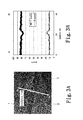
- FIG. 3A was the HRTEM image showing the two-grain boundary phases in Comparative Example 2 (which was the prior art).
- FIG. 3B showed the concentration distributions of Fe (T) and Nd (R) determined by the line analysis via STEM-EDS between A and B, wherein the analysis line A-B crossed the two-grain boundary phase 2 shown in FIG. 3A . It can be predicted from the element analysis via STEM-EDS that the two-grain boundary phase of Comparative Example 2 contained 75 at. % or more of Fe atoms and was ferromagnetic.
- FIG. 4A was the HRTEM image showing the two-grain boundary phases in Example 26 of the present invention.
- FIG. 4B showed the concentration distributions of Fe (T) and Nd (R) determined by the line analysis via STEM-EDS between A and B, wherein the analysis line A-B crossed the two-grain boundary phase 2 shown in FIG. 4A . It can be predicted from the element analysis via STEM-EDS that the two-grain boundary phase was formed in Example 26 with the concentration of Fe being lower than 10 at. %. Further, it is presumed that such a two-grain boundary phase was non-ferromagnetic.
- the crystal boundary phases contained the first crystal boundary phases and the second crystal boundary phases which two had different R-T-M ratios
- a two-grain boundary phase was formed with its concentration of the iron family elements being lower than that in the prior art.
- magnetic isolation among main phase crystal grains was improved, and an inhibitory effect on the demagnetization rate at a high temperature was produced.
- the two-grain boundary phase with lowered concentration of the iron family elements was also seen in Examples 1 to 31 in which the first crystal boundary phases and the second crystal boundary phases with different R-T-M ratios were contained.
- the sintered magnet contained the R-T-M based compound mentioned above and the numbers of 0, C and N atoms contained in the sintered magnet satisfied the following specific correlations. That was, when the numbers of O, C and N atoms were referred to as [O], [C] and [N] respectively, [O]/([C]+[N]) ⁇ 0.60. Thus, as [O]/([C]+[N]) ⁇ 0.60, the demagnetization rate D at a high temperature can be effectively inhibited.
- the R-T-M based crystal compound having R, T and M formed non-ferromagnetic crystal boundary phases in the sintered body by containing the rare earth element R, iron family element T and M (which formed the ternary eutectic point with R and T) in the crystal boundary phases which were subjected to a proper aging treatment and satisfy the correlations mentioned above.
- the concentration of T in the two-grain boundary phases can be lowered so that the two-grain boundary phases became non-ferromagnetic crystal boundary phases.
- the effect of cutting off the magnetic coupling among adjacent R 2 T 14 B main phase crystal grains can be improved so that the demagnetization rate at a high temperature was inhibited to a low level.
- a rare earth based magnet can be provided which can be used at a high temperature environment.
Applications Claiming Priority (2)
| Application Number | Priority Date | Filing Date | Title |
|---|---|---|---|
| JP2013263368A JP6142794B2 (ja) | 2013-12-20 | 2013-12-20 | 希土類磁石 |
| JP2013-263368 | 2013-12-20 |
Publications (2)
| Publication Number | Publication Date |
|---|---|
| US20150179319A1 US20150179319A1 (en) | 2015-06-25 |
| US10083783B2 true US10083783B2 (en) | 2018-09-25 |
Family
ID=53275519
Family Applications (1)
| Application Number | Title | Priority Date | Filing Date |
|---|---|---|---|
| US14/579,315 Active 2036-10-18 US10083783B2 (en) | 2013-12-20 | 2014-12-22 | Rare earth based magnet |
Country Status (4)
| Country | Link |
|---|---|
| US (1) | US10083783B2 (de) |
| JP (1) | JP6142794B2 (de) |
| CN (1) | CN104733146B (de) |
| DE (1) | DE102014118984B4 (de) |
Cited By (1)
| Publication number | Priority date | Publication date | Assignee | Title |
|---|---|---|---|---|
| US20170250014A1 (en) * | 2016-02-29 | 2017-08-31 | Tdk Corporation | Rare earth permanent magnet |
Families Citing this family (9)
| Publication number | Priority date | Publication date | Assignee | Title |
|---|---|---|---|---|
| JP6142792B2 (ja) * | 2013-12-20 | 2017-06-07 | Tdk株式会社 | 希土類磁石 |
| JP6142793B2 (ja) * | 2013-12-20 | 2017-06-07 | Tdk株式会社 | 希土類磁石 |
| JP6474043B2 (ja) * | 2015-08-26 | 2019-02-27 | 日立金属株式会社 | R−t−b系焼結磁石 |
| US10529473B2 (en) * | 2016-03-28 | 2020-01-07 | Tdk Corporation | R-T-B based permanent magnet |
| JP6702215B2 (ja) * | 2017-02-02 | 2020-05-27 | 日立金属株式会社 | R−t−b系焼結磁石 |
| JP2018153008A (ja) * | 2017-03-13 | 2018-09-27 | Tdk株式会社 | モータ |
| CN108878090B (zh) * | 2018-06-25 | 2020-05-12 | 天津三环乐喜新材料有限公司 | 一种无重稀土的钕铁硼烧结磁体及其制备方法 |
| JP7091562B2 (ja) * | 2018-12-29 | 2022-06-27 | 三環瓦克華(北京)磁性器件有限公司 | 希土類磁石、希土類スパッタリング磁石、希土類拡散磁石及びその製造方法 |
| JP7196708B2 (ja) * | 2019-03-18 | 2022-12-27 | Tdk株式会社 | R‐t‐b系永久磁石 |
Citations (13)
| Publication number | Priority date | Publication date | Assignee | Title |
|---|---|---|---|---|
| JP2002327255A (ja) | 2001-03-01 | 2002-11-15 | Tdk Corp | 焼結磁石 |
| JP2003031409A (ja) | 2001-07-18 | 2003-01-31 | Hitachi Metals Ltd | 耐食性に優れた希土類焼結磁石 |
| JP2011216678A (ja) | 2010-03-31 | 2011-10-27 | Nitto Denko Corp | R−t−b系希土類永久磁石 |
| WO2012002060A1 (ja) * | 2010-06-29 | 2012-01-05 | 昭和電工株式会社 | R-t-b系希土類永久磁石、モーター、自動車、発電機、風力発電装置 |
| JP2012015168A (ja) | 2010-06-29 | 2012-01-19 | Showa Denko Kk | R−t−b系希土類永久磁石、モーター、自動車、発電機、風力発電装置 |
| US20120024429A1 (en) | 2010-07-27 | 2012-02-02 | Tdk Corporation | Rare earth sintered magnet |
| US20120235778A1 (en) | 2011-03-18 | 2012-09-20 | Tdk Corporation | R-t-b rare earth sintered magnet |
| JP2012212808A (ja) | 2011-03-31 | 2012-11-01 | Tdk Corp | 希土類焼結磁石の製造方法 |
| WO2013008756A1 (ja) | 2011-07-08 | 2013-01-17 | 昭和電工株式会社 | R-t-b系希土類焼結磁石用合金、r-t-b系希土類焼結磁石用合金の製造方法、r-t-b系希土類焼結磁石用合金材料、r-t-b系希土類焼結磁石、r-t-b系希土類焼結磁石の製造方法およびモーター |
| JP2013013870A (ja) | 2011-07-06 | 2013-01-24 | Isomura Hosui Kiko Co Ltd | 凝集剤注入方法及び注入装置 |
| JP2013045844A (ja) | 2011-08-23 | 2013-03-04 | Toyota Motor Corp | 希土類磁石の製造方法、及び希土類磁石 |
| US20150179317A1 (en) * | 2013-12-20 | 2015-06-25 | Tdk Corporation | Rare earth based magnet |
| US20150179318A1 (en) * | 2013-12-20 | 2015-06-25 | Tdk Corporation | Rare earth based magnet |
Family Cites Families (8)
| Publication number | Priority date | Publication date | Assignee | Title |
|---|---|---|---|---|
| EP1073069A1 (de) * | 1993-11-02 | 2001-01-31 | TDK Corporation | Herstellung eines Dauermagnets |
| EP1059645B1 (de) * | 1999-06-08 | 2006-06-14 | Shin-Etsu Chemical Co., Ltd. | Dünnes Band einer dauermagnetischen Legierung auf Seltenerdbasis |
| JP4254121B2 (ja) * | 2002-04-03 | 2009-04-15 | 日立金属株式会社 | 希土類焼結磁石およびその製造方法 |
| JP4840606B2 (ja) * | 2006-11-17 | 2011-12-21 | 信越化学工業株式会社 | 希土類永久磁石の製造方法 |
| JP5218368B2 (ja) * | 2009-10-10 | 2013-06-26 | 株式会社豊田中央研究所 | 希土類磁石材およびその製造方法 |
| JP5870522B2 (ja) * | 2010-07-14 | 2016-03-01 | トヨタ自動車株式会社 | 永久磁石の製造方法 |
| JP6089535B2 (ja) * | 2011-10-28 | 2017-03-08 | Tdk株式会社 | R−t−b系焼結磁石 |
| JP5338956B2 (ja) * | 2011-11-29 | 2013-11-13 | Tdk株式会社 | 希土類焼結磁石 |
-
2013
- 2013-12-20 JP JP2013263368A patent/JP6142794B2/ja active Active
-
2014
- 2014-12-18 DE DE102014118984.1A patent/DE102014118984B4/de active Active
- 2014-12-19 CN CN201410799883.7A patent/CN104733146B/zh active Active
- 2014-12-22 US US14/579,315 patent/US10083783B2/en active Active
Patent Citations (18)
| Publication number | Priority date | Publication date | Assignee | Title |
|---|---|---|---|---|
| JP2002327255A (ja) | 2001-03-01 | 2002-11-15 | Tdk Corp | 焼結磁石 |
| JP2003031409A (ja) | 2001-07-18 | 2003-01-31 | Hitachi Metals Ltd | 耐食性に優れた希土類焼結磁石 |
| JP2011216678A (ja) | 2010-03-31 | 2011-10-27 | Nitto Denko Corp | R−t−b系希土類永久磁石 |
| WO2012002060A1 (ja) * | 2010-06-29 | 2012-01-05 | 昭和電工株式会社 | R-t-b系希土類永久磁石、モーター、自動車、発電機、風力発電装置 |
| JP2012015168A (ja) | 2010-06-29 | 2012-01-19 | Showa Denko Kk | R−t−b系希土類永久磁石、モーター、自動車、発電機、風力発電装置 |
| JP2012015169A (ja) | 2010-06-29 | 2012-01-19 | Showa Denko Kk | R−t−b系希土類永久磁石、モーター、自動車、発電機、風力発電装置 |
| US20130092868A1 (en) * | 2010-06-29 | 2013-04-18 | Showa Denko K.K. | R-t-b-based rare earth permanent magnet, motor, automobile, power generator, and wind power-generating apparatus |
| US20120024429A1 (en) | 2010-07-27 | 2012-02-02 | Tdk Corporation | Rare earth sintered magnet |
| JP2012199270A (ja) | 2011-03-18 | 2012-10-18 | Tdk Corp | R−t−b系希土類焼結磁石 |
| US20120235778A1 (en) | 2011-03-18 | 2012-09-20 | Tdk Corporation | R-t-b rare earth sintered magnet |
| JP2012212808A (ja) | 2011-03-31 | 2012-11-01 | Tdk Corp | 希土類焼結磁石の製造方法 |
| JP2013013870A (ja) | 2011-07-06 | 2013-01-24 | Isomura Hosui Kiko Co Ltd | 凝集剤注入方法及び注入装置 |
| WO2013008756A1 (ja) | 2011-07-08 | 2013-01-17 | 昭和電工株式会社 | R-t-b系希土類焼結磁石用合金、r-t-b系希土類焼結磁石用合金の製造方法、r-t-b系希土類焼結磁石用合金材料、r-t-b系希土類焼結磁石、r-t-b系希土類焼結磁石の製造方法およびモーター |
| US20140132377A1 (en) | 2011-07-08 | 2014-05-15 | Showa Denko K.K. | Alloy for r-t-b-based rare earth sintered magnet, process of producing alloy for r-t-b-based rare earth sintered magnet, alloy material for r-t-b-based rare earth sintered magnet, r-t-b-based rare earth sintered magnet, process of producing r-t-b-based rare earth sintered magnet, and motor |
| JP2013045844A (ja) | 2011-08-23 | 2013-03-04 | Toyota Motor Corp | 希土類磁石の製造方法、及び希土類磁石 |
| US20140191833A1 (en) | 2011-08-23 | 2014-07-10 | Noritsugu Sakuma | Method for producing rare earth magnets, and rare earth magnets |
| US20150179317A1 (en) * | 2013-12-20 | 2015-06-25 | Tdk Corporation | Rare earth based magnet |
| US20150179318A1 (en) * | 2013-12-20 | 2015-06-25 | Tdk Corporation | Rare earth based magnet |
Cited By (2)
| Publication number | Priority date | Publication date | Assignee | Title |
|---|---|---|---|---|
| US20170250014A1 (en) * | 2016-02-29 | 2017-08-31 | Tdk Corporation | Rare earth permanent magnet |
| US10453595B2 (en) * | 2016-02-29 | 2019-10-22 | Tdk Corporation | Rare earth permanent magnet |
Also Published As
| Publication number | Publication date |
|---|---|
| DE102014118984B4 (de) | 2018-08-30 |
| JP6142794B2 (ja) | 2017-06-07 |
| CN104733146B (zh) | 2017-06-23 |
| CN104733146A (zh) | 2015-06-24 |
| JP2015119132A (ja) | 2015-06-25 |
| DE102014118984A1 (de) | 2015-06-25 |
| US20150179319A1 (en) | 2015-06-25 |
Similar Documents
| Publication | Publication Date | Title |
|---|---|---|
| US10083783B2 (en) | Rare earth based magnet | |
| US10096412B2 (en) | Rare earth based magnet | |
| US10256016B2 (en) | Rare earth based magnet | |
| US7740715B2 (en) | R-T-B based sintered magnet | |
| JP4831253B2 (ja) | R−T−Cu−Mn−B系焼結磁石 | |
| US10923256B2 (en) | R-T-B-based sintered magnet and method for producing same | |
| US20130068992A1 (en) | Method for producing rare earth permanent magnets, and rare earth permanent magnets | |
| CN104395971A (zh) | 烧结磁铁 | |
| JP2016152246A (ja) | 希土類系永久磁石 | |
| JP2016154219A (ja) | 希土類系永久磁石 | |
| US10090087B2 (en) | Rare earth based magnet | |
| JP2019036707A (ja) | R−t−b系焼結永久磁石 | |
| Xu et al. | Influence of Ti addition on microstructure and magnetic properties of a heavy-rare-earth-free Nd-Fe-B sintered magnet | |
| US10109402B2 (en) | Rare earth based magnet | |
| US10020099B2 (en) | Rare earth based magnet | |
| US9548149B2 (en) | Rare earth based magnet | |
| JP2015122395A (ja) | R−t−b系焼結磁石の製造方法 | |
| JP2007294917A (ja) | R−t−b系焼結磁石及びr−t−b系焼結磁石の製造方法 | |
| JP6511844B2 (ja) | R−t−b系焼結磁石 | |
| US10546672B2 (en) | Rare earth based magnet | |
| JPS6247455A (ja) | 高性能永久磁石材料 | |
| Lee et al. | Coercivity Enhancement of Nd-Fe-B Powders via Grain Boundary Diffusion with a Tb/Cu Mixture | |
| JPH06256913A (ja) | 永久磁石材料 |
Legal Events
| Date | Code | Title | Description |
|---|---|---|---|
| AS | Assignment |
Owner name: TDK CORPORATION, JAPAN Free format text: ASSIGNMENT OF ASSIGNORS INTEREST;ASSIGNORS:FUJIKAWA, YOSHINORI;NAGAMINE, YUKI;OKAWA, WAKAKO;AND OTHERS;SIGNING DATES FROM 20140703 TO 20140710;REEL/FRAME:034569/0557 |
|
| STCF | Information on status: patent grant |
Free format text: PATENTED CASE |
|
| MAFP | Maintenance fee payment |
Free format text: PAYMENT OF MAINTENANCE FEE, 4TH YEAR, LARGE ENTITY (ORIGINAL EVENT CODE: M1551); ENTITY STATUS OF PATENT OWNER: LARGE ENTITY Year of fee payment: 4 |