KR20110104084A - Immersion lithography fluid control system - Google Patents
Immersion lithography fluid control system Download PDFInfo
- Publication number
- KR20110104084A KR20110104084A KR1020117018017A KR20117018017A KR20110104084A KR 20110104084 A KR20110104084 A KR 20110104084A KR 1020117018017 A KR1020117018017 A KR 1020117018017A KR 20117018017 A KR20117018017 A KR 20117018017A KR 20110104084 A KR20110104084 A KR 20110104084A
- Authority
- KR
- South Korea
- Prior art keywords
- compressed gas
- fluid
- exposure area
- nozzles
- workpiece
- Prior art date
Links
Images


Classifications
-
- G—PHYSICS
- G03—PHOTOGRAPHY; CINEMATOGRAPHY; ANALOGOUS TECHNIQUES USING WAVES OTHER THAN OPTICAL WAVES; ELECTROGRAPHY; HOLOGRAPHY
- G03F—PHOTOMECHANICAL PRODUCTION OF TEXTURED OR PATTERNED SURFACES, e.g. FOR PRINTING, FOR PROCESSING OF SEMICONDUCTOR DEVICES; MATERIALS THEREFOR; ORIGINALS THEREFOR; APPARATUS SPECIALLY ADAPTED THEREFOR
- G03F7/00—Photomechanical, e.g. photolithographic, production of textured or patterned surfaces, e.g. printing surfaces; Materials therefor, e.g. comprising photoresists; Apparatus specially adapted therefor
- G03F7/70—Microphotolithographic exposure; Apparatus therefor
- G03F7/70216—Mask projection systems
- G03F7/70341—Details of immersion lithography aspects, e.g. exposure media or control of immersion liquid supply
-
- G—PHYSICS
- G03—PHOTOGRAPHY; CINEMATOGRAPHY; ANALOGOUS TECHNIQUES USING WAVES OTHER THAN OPTICAL WAVES; ELECTROGRAPHY; HOLOGRAPHY
- G03B—APPARATUS OR ARRANGEMENTS FOR TAKING PHOTOGRAPHS OR FOR PROJECTING OR VIEWING THEM; APPARATUS OR ARRANGEMENTS EMPLOYING ANALOGOUS TECHNIQUES USING WAVES OTHER THAN OPTICAL WAVES; ACCESSORIES THEREFOR
- G03B27/00—Photographic printing apparatus
- G03B27/32—Projection printing apparatus, e.g. enlarger, copying camera
- G03B27/52—Details
- G03B27/522—Projection optics
-
- G—PHYSICS
- G03—PHOTOGRAPHY; CINEMATOGRAPHY; ANALOGOUS TECHNIQUES USING WAVES OTHER THAN OPTICAL WAVES; ELECTROGRAPHY; HOLOGRAPHY
- G03F—PHOTOMECHANICAL PRODUCTION OF TEXTURED OR PATTERNED SURFACES, e.g. FOR PRINTING, FOR PROCESSING OF SEMICONDUCTOR DEVICES; MATERIALS THEREFOR; ORIGINALS THEREFOR; APPARATUS SPECIALLY ADAPTED THEREFOR
- G03F7/00—Photomechanical, e.g. photolithographic, production of textured or patterned surfaces, e.g. printing surfaces; Materials therefor, e.g. comprising photoresists; Apparatus specially adapted therefor
- G03F7/20—Exposure; Apparatus therefor
- G03F7/2041—Exposure; Apparatus therefor in the presence of a fluid, e.g. immersion; using fluid cooling means
-
- G—PHYSICS
- G03—PHOTOGRAPHY; CINEMATOGRAPHY; ANALOGOUS TECHNIQUES USING WAVES OTHER THAN OPTICAL WAVES; ELECTROGRAPHY; HOLOGRAPHY
- G03F—PHOTOMECHANICAL PRODUCTION OF TEXTURED OR PATTERNED SURFACES, e.g. FOR PRINTING, FOR PROCESSING OF SEMICONDUCTOR DEVICES; MATERIALS THEREFOR; ORIGINALS THEREFOR; APPARATUS SPECIALLY ADAPTED THEREFOR
- G03F7/00—Photomechanical, e.g. photolithographic, production of textured or patterned surfaces, e.g. printing surfaces; Materials therefor, e.g. comprising photoresists; Apparatus specially adapted therefor
- G03F7/70—Microphotolithographic exposure; Apparatus therefor
- G03F7/708—Construction of apparatus, e.g. environment aspects, hygiene aspects or materials
- G03F7/70808—Construction details, e.g. housing, load-lock, seals or windows for passing light in or out of apparatus
-
- H—ELECTRICITY
- H01—ELECTRIC ELEMENTS
- H01L—SEMICONDUCTOR DEVICES NOT COVERED BY CLASS H10
- H01L21/00—Processes or apparatus adapted for the manufacture or treatment of semiconductor or solid state devices or of parts thereof
- H01L21/02—Manufacture or treatment of semiconductor devices or of parts thereof
- H01L21/027—Making masks on semiconductor bodies for further photolithographic processing not provided for in group H01L21/18 or H01L21/34
- H01L21/0271—Making masks on semiconductor bodies for further photolithographic processing not provided for in group H01L21/18 or H01L21/34 comprising organic layers
- H01L21/0273—Making masks on semiconductor bodies for further photolithographic processing not provided for in group H01L21/18 or H01L21/34 comprising organic layers characterised by the treatment of photoresist layers
Abstract
액침 리소그래피용 유체 제어 시스템이 렌즈와 같은 광학 부재, 그 사이에 갭을 갖는 광학 부재의 반대편에 배치된 표면을 갖는 반도체 웨이퍼와 같은 피가공물, 갭 내의 특정한 노광 영역에 물과 같은 액침액를 제공하기 위한 유체 공급 장치, 및 이 액침 리소그래피 동작이 실행되는 동안 적어도 액침액이 노광 영역과 그 부근에서 유지되도록 유체에 대한 힘을 활성화하는 유체 제어 장치로 형성된다. 압축 가스는 그 위치를 유지하도록 유체상에 유체역학적 힘을 인가하기 위해 야기될 수 있다.Fluid control systems for immersion lithography provide workpieces, such as semiconductor wafers, having an optical member such as a lens, a surface disposed opposite the optical member having a gap therebetween, and for providing an immersion liquid such as water to a particular exposure area within the gap. A fluid supply device, and a fluid control device that activates a force on the fluid such that at least the immersion liquid is maintained in and near the exposure area while the immersion lithography operation is performed. Compressed gas may be caused to apply hydrodynamic forces on the fluid to maintain its position.
Description
본 출원은 2003년 4월 9일자로 출원된 미국 가출원 제 60/462,142호에 대한 우선권을 주장하며, 이는 전부 참조로 포함된다.This application claims priority to US Provisional Application No. 60 / 462,142, filed April 9, 2003, which is incorporated by reference in its entirety.
본 발명은 WO99/49504 에 개시된 바와 같이 웨이퍼와 같은 피가공물 (workpiece) 과 그 피가공물상에 레티클의 이미지를 투영하기 위한 광학 시스템의 렌즈와 같은 최종 스테이지 광학 부재 사이의 공간으로 공급된 유체 재료를 갖는 액침 리소그래피 시스템에 관한 것이다. 공급된 유체 재료는 순수한 물일 수 있고, 그 존재에 의해 광학 시스템의 성능과 노광 품질을 향상시킬 수 있다.The invention relates to a fluid material supplied into a space between a workpiece such as a wafer and a final stage optical member such as a lens of an optical system for projecting an image of a reticle onto the workpiece as disclosed in WO99 / 49504. To an immersion lithography system. The supplied fluid material may be pure water, and its presence may improve the performance and exposure quality of the optical system.
피가공물과 최종 스테이지 광학 부재 사이의 공간에 그렇게 공급된 유체 재료는 광학 시스템으로부터의 방사 에너지로 인하여 온도를 상승시키려는 경향이 있으므로 이에 의해 그 굴절 계수를 변경시킬 수 있다. 또한, 연장된 시간 기간에 유체 재료가 광학 부재와 피가공물과 접촉하는 상태로 있다면, 이는 오염되기 쉬우며, 또한 이것은 그 굴절 계수에 영향을 준다. 또한, 유체 재료는 피가공물이 최종 스테이지 광학 부재에 대하여 이동되기 때문에 피가공물과 최종 스테이지 광학 부재 사이의 공간 밖으로 누출되는 경향이 있다. 이러한 이유들로, 액침 리소그래피 시스템에는 리소그래피 유체를 계속 보충하기 위한 효율적인 유체 제어 시스템이 제공되어야만 한다.The fluid material so supplied to the space between the workpiece and the final stage optical member tends to raise the temperature due to the radiant energy from the optical system, thereby changing its refractive index. In addition, if the fluid material remains in contact with the optical member and the workpiece in an extended period of time, it is susceptible to contamination, which also affects its refractive index. In addition, the fluid material tends to leak out of the space between the workpiece and the final stage optical member because the workpiece is moved relative to the final stage optical member. For these reasons, the immersion lithography system must be provided with an efficient fluid control system for continuously replenishing the lithographic fluid.
액침 리소그래피 장치를 위한 유체 제어 시스템과 관련된 문제는 최종 스테이지 광학 부재와 피가공물 사이의 공간을 채우는 유체 재료를 어떻게 제어하거나 또는 포함하느냐에 있다.A problem associated with a fluid control system for an immersion lithography apparatus is how to control or include the fluid material that fills the space between the final stage optical member and the workpiece.
본 발명에 따른 유체 제어 시스템은 액침 리소그래피 장치에 사용되며, 광학 부재, 그 사이에 갭을 갖는 이 광학 부재와 반대편에 배치된 표면을 갖는 피가공물, 갭 내의 특정한 노광 영역에 유체를 제공하기 위한 유체 공급 장치로서, 노광 영역내와 그 부근에 유체를 유지하여 의도된 제한 영역으로부터 떨어져 이동하는 것을 방지하는 즉, 노광 영역 외부의 특정한 주변 영역으로 들어가는 것을 방지하도록 갭으로 공급되는 유체에 대한 힘을 활성화하도록 구성된 유체 제어 장치로서 널리 지칭될 수 있는 상기 유체 공급장치를 포함한다.The fluid control system according to the present invention is used in an immersion lithography apparatus, and includes an optical member, a workpiece having a surface disposed opposite the optical member having a gap therebetween, and a fluid for providing a fluid to a specific exposure area within the gap. As a supply device, a force is applied to a fluid supplied into a gap to hold fluid in and near the exposure area to prevent movement away from the intended restricted area, i.e., to prevent entry into a specific peripheral area outside the exposure area. And a fluid supply device, which may be widely referred to as a fluid control device, configured to.
위에서, 유체에 공급되는 힘은 활성화될 수 있는 종류의 힘으로서 설명되어 있다. 이것은 힘 자체가 제어가능한 형태의 것이며 한정된 벽 (wall) 과 같은 고정된 오브젝트로부터의 반응력을 배제한다는 것을 의미한다. 액침 유체에 대한 힘을 활성화하는 복수의 예들이 고려된다. 일 예는 노광 영역내와 그 부근에서 유체를 포함하도록 즉, 유체가 흘러나오는 것을 원하지 않는 주변 영역에 유체가 들어가는 것을 방지하도록 유체역학적 힘이 배열되어 압축 가스 소스로부터의 가스 흐름을 활성화하는 것이다.In the above, the force supplied to the fluid is described as a kind of force that can be activated. This means that the force itself is in a controllable form and excludes the reaction force from a fixed object such as a confined wall. A plurality of examples of activating a force on the immersion fluid are contemplated. One example is that hydrodynamic forces are arranged to activate the gas flow from the compressed gas source to include the fluid in and near the exposure area, i.e., to prevent the fluid from entering the peripheral area where fluid is not desired to flow out.
또 다른 예는 액침액이 자기적으로 반응하는 물질인 경우에 정자기력을 활성화하는 것이다. 강자성 물질의 분말이 유체의 자기 특성을 향상시키기 위해 부가될 수도 있다.Another example is to activate the static magnetic force when the immersion liquid is a magnetically reacting substance. Powders of ferromagnetic materials may be added to improve the magnetic properties of the fluid.
또 다른 예는 액침액으로서 유동 (rheological) 유체를 사용하는 것이다. 전기유동 유체의 경우에, 적절한 세기의 정전기장이 유체의 점도를 증가시켜 실질적으로 유체를 응고시키기 위하여 적절히 배치된 캐패시터 전극 쌍에 의해 활성화될 수도 있다. 자기유동 유체의 경우, 적절한 세기의 자기장은 포함된 액침액을 유지하도록 적절히 배치된 코일들에 의해 활성화될 수도 있다.Another example is to use a rheological fluid as the immersion liquid. In the case of an electrofluid fluid, an electrostatic field of appropriate strength may be activated by a pair of capacitor electrodes arranged appropriately to increase the viscosity of the fluid and substantially solidify the fluid. In the case of a magnetorheological fluid, a magnetic field of appropriate intensity may be activated by coils properly arranged to retain the immersion liquid contained therein.
본 발명에 따르면, 유체가 흘러나오는 것을 원하지 않는 주변 영역에 유체가 들어가는 것을 방지할 수 있다.According to the present invention, it is possible to prevent the fluid from entering the peripheral region where the fluid is not desired to flow out.
다른 목적들과 그 이점들을 갖는 본 발명은 첨부된 도면들과 함께 이하의 상세한 설명부를 참조함으로써 가장 잘 이해될 수 있다.
도 1 은 본 발명의 방법들과 시스템들이 적용될 수 있는 액침 리소그래피 장치의 개략 단면도이다.
도 2 는 반도체 장치들이 본 발명에 따라 도 1 에 나타낸 장치를 사용하여 제조되는 예시적인 공정을 나타내는 흐름도이다.
도 3 은 본 발명에 따른 반도체 장치들을 제조하는 경우에 도 2 에 나타낸 웨이퍼 처리 단계의 흐름도이다.
도 4 는 본 발명을 구현하는 유체 제어 시스템을 포함하는 도 1 에 나타낸 구조의 일반적인 액침 리소그래피 장치의 일부에 대한 개략적인 종단면도이다.
도 5 는 도 4 에 나타낸 유체 제어 시스템을 포함하는 액침 리소그래피 장치의 일부에 대한 개략적인 측면도이다.
도 6 은 배기 메니폴드를 포함하는 액침 리소그래피 장치의 바람직한 실시형태의 일부에 대한 개략적인 측면도이다.
도 7 은 본 발명의 제 2 실시형태에 따른 또 다른 유체 제어 시스템을 포함하는 도 1 에 나타낸 구조의 일반적인 액침 리소그래피 장치의 일부에 대한 개략적인 종단면도이다.
도 8 은 본 발명의 제 3 실시형태에 따른 유체 제어 시스템을 포함하는 액침 리소그래피 장치의 일부에 대한 개략적인 측면도이다.
도 9 는 본 발명의 제 3 실시형태에 따른 또 다른 유체 제어 시스템을 포함하는 액침 리소그래피 장치의 일부에 대한 개략적인 측면도이다.
여기서는 전반적으로, 유사하거나 등가인 구성요소들은 상이한 도면들에서 동일한 부호 또는 번호로 표시될 수 있으며 설명의 간결성을 위해 반복적으로 설명되지 않을 수 있다.DETAILED DESCRIPTION The present invention having other objects and advantages can be best understood by reference to the following detailed description in conjunction with the accompanying drawings.
1 is a schematic cross-sectional view of an immersion lithographic apparatus to which the methods and systems of the present invention may be applied.
2 is a flow diagram illustrating an exemplary process in which semiconductor devices are fabricated using the device shown in FIG. 1 in accordance with the present invention.
3 is a flowchart of the wafer processing step shown in FIG. 2 in the case of manufacturing the semiconductor devices according to the present invention.
4 is a schematic longitudinal cross-sectional view of a portion of a general immersion lithographic apparatus of the structure shown in FIG. 1 including a fluid control system embodying the present invention.
FIG. 5 is a schematic side view of a portion of an immersion lithographic apparatus including the fluid control system shown in FIG. 4.
6 is a schematic side view of a portion of a preferred embodiment of an immersion lithographic apparatus including an exhaust manifold.
FIG. 7 is a schematic longitudinal cross-sectional view of a portion of a general immersion lithographic apparatus of the structure shown in FIG. 1 including yet another fluid control system according to a second embodiment of the present invention.
8 is a schematic side view of a portion of an immersion lithographic apparatus including a fluid control system according to a third embodiment of the present invention.
9 is a schematic side view of a portion of an immersion lithographic apparatus including another fluid control system according to a third embodiment of the present invention.
Overall, like or equivalent components may be denoted by the same reference numerals or numbers in different drawings and may not be repeatedly described for the sake of brevity of description.
도 1 은 본 발명의 유체 제어 시스템을 포함할 수도 있는 액침 리소그래피 장치 (100) 를 나타낸다.1 shows an immersion
도 1 에 나타낸 바와 같이, 액침 리소그래피 장치 (100) 는 KrF 엑시머 레이저 유닛과 같은 광원, 옵티컬 인테그레이터 (호모지나이저) 및 렌즈을 포함하고, 레티클 (R) 상의 패턴에 입사되도록 248nm 파장을 갖는 펄스화된 자외선광 (IL) 을 방출하는 기능을 하는 조명 광학 유닛 (1) 을 포함한다. 레티클 (R) 상의 패턴은 텔레센트릭 (telecentric) 광 투영 유닛 (PL) 을 통해 특정한 배율 (예를 들어 1/4 또는 1/5) 로 포토레지스트를 사용하여 코팅된 웨이퍼 (W) 상에 투영된다. 펄스화된 광 (IL) 은 택일적으로 파장 193nm 의 ArF 엑시머 레이저 광, 파장 157 nm 의 F2 레이저 광, 또는 파장 365nm 의 수은 램프의 i-선이 될 수 있다. 이어서, 도 1 에 나타낸 바와 같은 X, Y, Z 축들을 갖는 좌표 시스템이 리소그래피 장치 (100) 의 구조 및 기능들을 설명함에 있어 방향들을 설명하는데 참조된다. 명세서 및 설명서의 편의를 위해, 광 투영 유닛 (PL) 은 웨이퍼 (W) 반대편에 배치된 그 최종 스테이지 광학 소자 (4) (렌즈 등) 와 그 구성요소들의 나머지를 포함하는 원통형 하우징 (3) 만으로 도 1 에 예시된다.As shown in FIG. 1, the
레티클 (R) 은 X 방향, Y 방향 및 Z 축 주위의 회전 방향으로 레티클 (R) 을 이동시키기 위한 메커니즘을 포함하는 레티클 스테이지 (RST) 로 지지된다. 레티클 스테이지 (RST) 상의 레티클 (R) 의 2 차원적 위치 및 배향은 실시간으로 레이저 간섭계 (미도시) 에 의해 검출되고, 레티클 (R) 의 위치결정은 이렇게 행해진 검출에 기초하여 주 제어 유닛 (14) 에 의해 수행된다.The reticle R is supported by a reticle stage RST comprising a mechanism for moving the reticle R in the X, Y and rotational directions around the Z axis. The two-dimensional position and orientation of the reticle R on the reticle stage RST is detected by a laser interferometer (not shown) in real time, and the positioning of the reticle R is based on the detection thus made. Is performed by
웨이퍼 (W) 는 웨이퍼 (W) 의 경사각과 포커싱 위치 (Z축을 따름) 를 제어하기 위한 Z 스테이지 (9) 상의 웨이퍼 홀더 (미도시) 에 의해 지지된다. Z 스테이지 (9) 는 광 투영 유닛 (PL) 의 이미지-형성 표면과 실질적으로 평행한 XY 평면으로 이동하도록 구성된 XY 스테이지 (10) 에 부착된다. XY 스테이지 (10) 는 베이스 (11) 상에 설정된다. 따라서, Z 스테이지 (9) 는 오토-포커싱 및 오토-레벨링 방법에 의해 웨이퍼 (W) 의 경사각과 포커싱 위치 (Z축을 따름) 를 조정함으로써 광 투영 유닛 (PL) 의 이미지 표면과 웨이퍼 표면을 매칭하는 기능을 하며, XY 스테이지 (10) 는 X 방향과 Y 방향으로 웨이퍼 (W) 의 위치를 조정하는 기능을 한다.The wafer W is supported by a wafer holder (not shown) on the
Z 스테이지 (9)(또한 이하에서는 웨이퍼 (W)) 의 2차원적 위치 및 배향은 Z 스테이지 (9) 에 부착된 이동 거울 (12) 에 대하여 또 다른 레이저 간섭계 (13) 에 의해 실시간으로 모니터링된다. 이 모니터링의 결과에 기초한 제어 데이터는 수신된 제어 데이터에 따라 주 제어 유닛 (14) 으로부터 Z 스테이지 (9) 와 XY 스테이지 (10) 의 움직임을 제어하도록 구성된 스테이지 구동 유닛 (15) 으로 송신된다. 노광시에, 투영광은 스텝-앤드-리피트 루틴 또는 스텝-앤드-스캔 루틴으로 레티클 (R) 상의 패턴에 따라 웨이퍼 (W) (이하 피가공물 (W) 로 지칭함) 상의 서로 상이한 노광 위치들 중 하나의 위치에서 다른 위치로 순차적으로 이동하도록 구성되어 있다.The two-dimensional position and orientation of the Z stage 9 (also hereafter the wafer W) is monitored in real time by another
도 1 을 참조하여 설명되는 리소그래피 장치 (100) 는 액침 리소그래피 장치이므로 적어도 레티클 (R) 의 패턴 이미지가 피가공물 (W) 상에 투영되는 동안에 피가공물 (W) 의 표면과 광 투영 유닛 (PL) 의 최종 스테이지 광학 소자 (4) 의 하부 표면 사이의 공간 ("갭") 을 채우는 물과 같은 특정한 종류의 유체 (또는 "액침액") 를 가지도록 구성된다.Since the
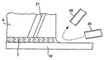
광 투영 유닛 (PL) 의 최종 스테이지 광학 소자 (4) 는 원통형 하우징 (3) 에 탈착가능하게 부착될 수도 있으며, 하우징 (3) 이 통상적으로 금속 재료를 포함하고 부식될 수 있기 때문에 액체 (7) 가 최종 스테이지 광학 소자 (4) 만 접촉하고 원통형 하우징 (3) 은 접촉하지 않도록 설계된다.The final stage optical element 4 of the light projection unit PL may be detachably attached to the
액체 (7) 는 온도 조절된 조건하에서 피가공물 (W) 위의 공간에 탱크, 압력 펌프, 및 온도 조절기 (개별적으로 도시하지 않음) 를 포함할 수도 있는 액체 공급 유닛 (5) 으로부터 공급되고, 액체 회수 유닛 (6) 에 의해 수집된다. 액체 (7) 의 온도는 리소그래피 장치 (100) 자체가 배치되는 챔버 내부의 온도와 대략적으로 동일하게 되도록 조절된다. 도면부호 21 은 액체 (7) 가 액체 공급 유닛 (5) 으로부터 공급되는 공급 노즐을 나타낸다. 도면부호 23 은 액체 (7) 가 회수 유닛 (6) 으로 수집되는 회수 노즐들을 나타낸다. 그러나, 도 1 을 참조하여 상술한 구조는 본 발명의 유체 제어 시스템을 적용할 수 있는 액침 리소그래피 장치의 범위를 제한하는 것으로 의도되지는 않는다. 즉, 본 발명의 유체 제어 시스템을 많은 다른 종류들의 액침 리소그래피 장치에 적용할 수 있다는 것은 말할 필요도 없다. 특히, 광 투영 유닛 (PL) 주위의 공급 및 회수 노즐들 (21 및 23) 의 개수와 배열은 액침액 (7) 의 매끄러운 흐름과 빠른 회수를 확립하기 위하여 다양한 방식들로 설계될 수도 있음을 상기해야 한다.The
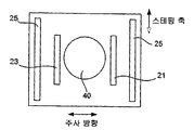
도 4 와 도 5 는 일반적으로 도 1 에 나타낸 바와 같이 구성된 액침 리소그래피 장치에 포함되는 것으로, 액체 (7) 를 제어하기 위한 고압 가스를 사용하는 것을 특징으로 하는 본 발명의 일 실시형태에 따른 유체 제어 시스템을 나타낸다. 도 4 와 도 5 에서, 도면부호 40 은 조명기 광학 유닛 (1) 으로부터의 광 (IL) 이 입사되는 조명 필드를 포함하는 영역 (이하 노광 영역이라 지칭함) 을 나타내므로 이것은 노광 공정 동안 액체 (7) 가 현재 상태를 유지해야 하는 영역이다. 이를 위하여, 압축 가스 소스 (미도시) 에 접속된 가스 배출구 (25) 는 액체 (7) 가 제한되도록 의도되는 노광 영역 (40) 을 포함하는 영역의 반대측 상에 제공된다. 도 5 에서, 도면부호 45 는 액체 (7) 가 들어가지 않도록 제어되는 "주변 영역" 으로 지칭될 수 있는 것을 나타낸다. 즉, 액체 (7) 는 피가공물을 주사함에 따라 최종 스테이지 광학 소자 (4) 에 대하여 이동하도록 강요될 수 있지만, 가스 배출구들 (25) 로부터의 압축 가스는 특정한 주변 영역 (45) 에 도달할 만큼 노광 영역 (40) 으로부터 떨어져 이동하지 않도록 액체 (7) 를 충분히 제한한 상태로 유지하는 기능을 한다. 따라서, 본 발명의 관점으로부터, 주변 영역 (45) 으로 여기에 특정된 영역은 액체 (7) 가 노광 영역 (40) 으로부터 떨어져 이동하도록 허용된 최대 거리를 규정하는 것으로 간주될 수 있다.4 and 5 are generally included in an immersion lithography apparatus constructed as shown in FIG. 1, in which a fluid control according to an embodiment of the present invention is characterized by the use of a high pressure gas for controlling the
가스 배출구들 (25) 의 물리적 정렬에 엄격한 조건은 없다. 압축 가스는 개별적인 노즐들 밖으로 흐를 수도 있거나 또는 액체 (7) 상에 균일한 유체역학적 힘을 인가하기 위해 더 많은 균일한 압력 파면 (wavefront) 을 형성하도록 압축 가스가 1 차원적으로 연장된 삽입 그루브 (groove) 들을 통해 균일하게 방출될 수 있도록 도 4 에 나타낸 바와 같이 공급 및 회수 노즐들 (21,23) 외부에 노광 영역 (40) 의 반대측상에 그루브들이 형성될 수 있다. 일 실시형태에서, 가스 배출구 (25) 들은 예시한 바와 같이 주사 방향들로 제공될 수도 있다. 다른 실시형태에서, 가스 배출구들은 또한 스테핑 (stepping) 축 방향 (미도시) 으로 제공될 수도 있다.There are no stringent conditions on the physical alignment of the
또 다른 실시형태에서, 가스 배출구들은 노광 영역 (40) 이 가스 배출구들로 둘러싸이도록 주사 방향 및 스테핑 방향으로 제공될 수도 있다. 이 경우, 가스 압력은 주사 방향들로 제공된 가스 배출구들과 스테핑 방향들로 제공된 가스 배출구들 사이에서 서로 다르게 될 수도 있다. 예를 들어, 주사 방향들로 제공된 배출구들의 가스 압력은 피가공물 (W) (XY 스테이지 (10)) 이 주사 방향으로 이동되는 동안 더 강해질 수도 있고, 스테핑 방향들로 제공된 배출구들의 가스 압력은 피가공물 (W) (XY 스테이지 (10)) 이 스테핑 방향으로 이동되는 동안 더 강해질 수도 있다. 또한, 다른 실시형태에서, 가스 배출구들은 노광 영역 (40) 이 가스 배출구들로 둘러싸이도록 제공될 수도 있다. 이 경우, 가스 압력들은 가스 배출구들의 위치에 기초하여 서로 다르게 될 수도 있거나 및/또는 피가공물 (W) (XY 스테이지 (10)) 의 움직임 (이동 속도와 이동 방향 등) 에 따라 변화될 수도 있다.In yet another embodiment, the gas outlets may be provided in the scanning direction and the stepping direction such that the
배출구들 (25) 밖으로의 가스 흐름에 의해 야기될 수도 있는 혼란을 최소화하기 위하여, 가스 공급 튜브들 또는 파이프들 (또는 "공급 메니폴드") 이 액체 공급 노즐 시스템의 나머지에 부착될 필요가 없을지라도 이 노즐들 또는 배출 그루브 (25) 들을 도 5 에 개략적으로 나타낸 바와 같이 피가공물 (W) 의 표면에 대하여 대각선으로 또는 비스듬히 배열하는 것이 바람직하다. 일반적으로, 액체 공급 및 회수는 양호한 밸런스가 존재하게 되도록 설계된다. 너무 많은 액체가 공급되면, 시스템에서 누출이 발생한다. 너무 많은 회수동작이 이용되면, 갭이 건조되거나 거품이 갭내로 들어올 수 있다.In order to minimize the confusion that may be caused by the gas flow out of the
공급되는 가스 압력은 시스템 구성에 의존한다. 그러나, 액침 액체를 제한하기 위해서는, 가스/액체 인터페이스에서 대략 15 내지 25m/sec의 속도를 가져야 한다. 하나의 특정 실시형태에서는, 20m/sec 로 규정되었다. 노즐 구성과 같은 인자들의 관점에서의 수용가능한 범위는 2-200m/sec 로 넓게 될 수도 있다.The gas pressure supplied depends on the system configuration. However, in order to limit the immersion liquid, it must have a speed of approximately 15 to 25 m / sec at the gas / liquid interface. In one specific embodiment, it is defined as 20 m / sec. The acceptable range in terms of factors such as nozzle configuration may be widened to 2-200 m / sec.
또한, 필요한 흐름 속도 (가스 압력) 는 피가공물 (W) 의 표면과 액체 (7) 간의 접촉각도 뿐만 아니라 스테이지 주사 속도에 의존한다. 스테이지 주사 속도는 10 mm/sec로부터 1000 mm/sec로 변화될 수 있고 또는 이보다 더 큰 것도 가능하다. 액체 (7) 와 피가공물 (W) 상의 저항 재료 사이의 접촉 각도는 저항 재료에 의존하고, 또한 그것이 어떻게 처리되었는냐에 의존한다. 어떠한 상부 코팅이 없는 표준 ArF 저항은 통상적으로 75°의 접촉각을 가질 것이다. 상부코팅을 추가하는 것은 110°또는 그 보다 크게 접촉각도를 증가시킬 수 있다. KrF 를 이용하면 접촉 각도는 대략 60°이다. 장래의 기술에 대해서, 접촉 각도는 변화될 것이다. 일반적으로, 접촉 각도를 높일수록, 낮은 압력이 필요하고 그 반대의 경우도 마찬가지이다. 또한, 노즐 설계와 주사 속도와 같은 다른 인자들도 필요한 압력에 영향을 줄 것이다.The required flow rate (gas pressure) also depends on the stage scan rate as well as the contact angle between the surface of the workpiece W and the
도 6 은 점 화살표로 개략적으로 표시되는 가스 흐름을 추가적으로 제어하도록 공급 메니폴드 (25) 에 부가하여 공급 가스를 제거하기 위한 배기 메니폴드 (26) 를 갖는 것을 특징으로 하는 본 발명의 실시형태를 나타낸다. 또한, 이는 액체 (7) 에 직접 노광된 가스를 제거함으로써 주사기 챔버의 습기를 감소시키는 특징도 가진다.FIG. 6 shows an embodiment of the invention characterized in that it has an
가스는 공기일 필요는 없다. 질소 등과 같은 어떤 유사한 가스가 사용될 수 있다. 또한, 공기보다도 물을 더 잘 흡수하는 가스는 물 수용의 관점에서 이점이 될 것이다.The gas need not be air. Any similar gas can be used, such as nitrogen. In addition, gases that absorb water better than air will be advantageous in terms of water acceptance.
일반적으로, 액침액 수용은 웨이퍼 스테이지의 이동이 이 방향으로 더 크게 됨에 따라 주사 방향에서는 더 곤란해진다. 공기 공급 및 배기 메니폴드는 스테핑 방향으로 부가될 수도 있거나 또는 대안적으로 공급구 또는 배출구에만 부가될 수 있다. 또한, 본 발명은 미국 특허 제 6,262,796호와 제 6,341,007호에 개시되는 트윈 스테이지 타입 (Twin-Stage-Type) 리소그래피 시스템에 적용될 수 도 있다.In general, immersion liquid reception becomes more difficult in the scanning direction as the movement of the wafer stage becomes larger in this direction. Air supply and exhaust manifolds may be added in the stepping direction or alternatively only at the supply or outlet. The present invention may also be applied to the Twin-Stage-Type lithography system disclosed in US Pat. Nos. 6,262,796 and 6,341,007.
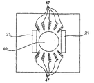
도 7 은 상술한 바와 같이 액체 (7) 를 노광 영역 (40) 의 내부와 바로이웃 부근에 포함시키고 그 액체 (7) 가 주변 영역 (45) 에 도달하는 것을 방지함으로써 액체 (7) 를 제어하는 정자기력 (magnetostatic force) 을 사용하는 것을 특징으로 하는 본 발명의 제 2 실시형태를 나타낸다. 통상적으로, 물은 액침 리소그래피에서 액침액으로 사용되고, 물은 자기적으로 반응하는 액체로 알려져 있으며 반자성체이다. 따라서, 자기력은 액체 (7) 가 한정되는 영역에 걸쳐서 적절한 자기장을 제공함으로써 이와 같은 유체 재료상에 인가될 수 있다. 도 7 은 자기장 발생기로서 함께 기능하는 복수의 전자기 코일들 (47) 이 노광 영역 (40) 주위에 배열되고 자기장은 액체 (7) 의 흐름을 제어하도록 발생되는 예를 나타낸다. 설명의 편의를 위해, 이 코일 (47) 들을 통하여 전류를 통과시키기 위한 회로는 생략된다.FIG. 7 shows the control of the
물과 같은 액침액의 자기적으로 응답하는 특징을 강화하기 위하여, Ni, Fe, Co 와 같은 강자성 물질의 분말이 액체 (7) 의 투명성 및 다른 광학 특성들에 불리하게 영향을 미치지 않을 정도로 액체 (7) 에 부가될 수도 있다.In order to reinforce the magnetically responsive nature of immersion liquids such as water, liquids such as powders of ferromagnetic materials such as Ni, Fe, Co do not adversely affect the transparency and other optical properties of
제 3 실시형태에 따른 본 발명은 최종 스테이지 광학 소자 (4) 와 피가공물 (W) 사이에 액침액으로서 전기유동적 유체 (ERF) 또는 자기유동적 유체 (MRF) 등과 같은 유동 유체를 사용하는 것을 특징으로 한다. ERF는 정상 상태하에서 매우 낮은 점도 (말하자면, 10Pa-s 보다 작음) 지만 전기장내에 있을 때 매우 높은 점도의 특성을 가지는 것을 특징으로 한다. MRF 는 정상 상태하에서 유사하게 매우 낮은 점도의 특성을 갖지만, 자기장내에 있을 때는 매우 높은 점도를 갖는 것을 특징으로 한다. 상기에서, “매우 높은 점도”라는 표현은 이 유체들이 더 측정할 수 없는 점도를 갖는 소위 빙엄 고체 (Bingham solid) 가 된다는 것을 의미한다.The present invention according to the third embodiment is characterized in that a flow fluid such as an electrofluidic fluid (ERF) or a magnetofluidic fluid (MRF) or the like is used as the immersion liquid between the final stage optical element 4 and the workpiece W. do. ERF is characterized by a very low viscosity under normal conditions (ie less than 10 Pa-s) but very high viscosity when in an electric field. MRF is similarly characterized by very low viscosity under steady state but very high viscosity when in a magnetic field. In the above, the expression “very high viscosity” means that these fluids become so-called Bingham solids with a viscosity that cannot be measured further.
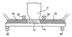
도 8 은 ERF (70) 를 사용하고, 이 예에서 정전기장의 발생기인 필드 발생기로서 종종 광범위하게 여기서 참조되는 것의 예로서 캐패시터 전극 (50) 들을 갖는 것을 특징으로 하는 액침 리소그래피를 위한 본 발명의 제 3 실시형태에 따른 유체 제어 시스템을 나타낸다. 캐패시터 전극 (50) 들은 도 8 에 나타낸 바와 같이 배치되어 있고, ERF (70) 를 노광 영역 (40) 에서 액체 상태로 유지하지만 액체 상태의 ERF (70) 가 노광 영역 (40) 의 중심이 되는 영역내에 포함되고 주변 영역에 들어가는 것을 방지하도록 주변 영역에서 도면 부호 71 로 표시된 바와 같이 응고시키도록 충분히 강한 것으로 고려되는 노광 영역 (40) 을 둘러싸는 영역에서 일반적으로 통상 이용가능한 ERF 종류를 응고시키도록 충분히 강한 것으로 고려되는 3-4kV/mm의 정전기장을 발생하도록 전압원 (52) 에 접속되어 있다.8 uses the
도 9 는 MRF (75) 를 사용하고, 피가공물 (W) 의 표면에 걸쳐서 약 0.1-0.8 테슬러의 정전기장을 발생하기 위한 코일 (60) 과 같은 자기장 발생기를 가지며, 코일들 (60,62) 이 스위칭 온 될 때 이에 의해 발생된 자기장들이 노광 영역 (40) 의 내부와 노광 영역의 부근에서 서로 효과적으로 상쇄되도록 노광 영역 (40) 의 내부와 노광 영역에 대하여 코일 (60) 에 의해 발생된 자기장에 동일한 자기장으로서 이것에 반대로 배향하는 자기장을 발생하도록 도 9 에 나타낸 바와 같이 배치된 또 다른 필드 발생기 (여기서는 반대 필드 발생기 (62) 라 지칭한다) 를 갖는 것을 특징으로 하는 액침 리소그래피를 위한 본 발명의 제 3 실시형태에 따른 또 다른 유체 제어 시스템을 나타낸다. 그 결과, 노광 영역 (40) 의 내부와 그 부근에서 MRF (75) 의 일부는 액체 상태로 남지만, 액체 상태의 MRF (75) 가 노광 영역 (40) 의 중심에 있는 영역내에 포함되고 이것이 주변 영역에 들어가는 것을 방지하도록 코일 (60) 에 의해 발생된 자기장으로 인해 주변 영역에서 도면부호 76 으로 표시된 바와 같이 MFR (75) 은 응고된다. 9 uses a
피가공물 (W) 이 광 투영 유닛 (PL) 하에서 주사될 때, 광 투영 유닛 (PL) 에 고정되는 반대 상쇄 필드의 위치는 피가공물 (W) 의 표면을 따라 이동한다. 반대 필드 발생기 (62) 에 의해 제공된 반대 필드는 유체 (75) 가 노광 영역 (40) 내부와 그 부근에서 액체 상태로 남아있도록 피가공물 (W) 의 표면상의 유체를 응고해제 (desolidify) 하거나 재응고 (resolidify) 하도록 기능한다.When the workpiece W is scanned under the light projection unit PL, the position of the opposite offset field fixed to the light projection unit PL moves along the surface of the workpiece W. FIG. The counter field provided by the
본 발명이 제한된 수의 실시형태들을 참조하여 상술하였을 지라도, 이들 실시형태들과 예시된 예들이 본 발명의 범위를 제한하도록 의도되지 않음은 말할 필요도 없다. 많은 변경과 변형이 본 발명의 범위내에서 가능하다. 예를 들어, 도 7 에서의 전자석 (47) 은 예시된 바와 같이 배열될 필요는 없다. 그러므로, 액침액의 종류과 그 흐름 속도에 따라, 더 많은 적절한 배열이 당업자에 의해 선택될 수도 있다.Although the present invention has been described above with reference to a limited number of embodiments, it goes without saying that these embodiments and the illustrated examples are not intended to limit the scope of the present invention. Many modifications and variations are possible within the scope of the invention. For example, the
다음으로, 도 2 는 본 발명을 구현하는 유체 제어 시스템을 포함하는 액침 리소그래피 장치를 사용하여 반도체 장치를 제작하기 위한 공정을 설명하기 위해 참조된다. 단계 301 에서, 장치의 기능과 성능 특성이 설계된다. 다음으로, 단계 302 에서, 패턴을 갖는 마스크 (레티클) 이 이전 설계 단계에 따라 설계되고, 대응하는 단계 303 에서, 웨이퍼가 실리콘 재료로 제조된다. 단계 302 에서 설계된 마스크 패턴은 상술한 시스템들과 같은 포토리소그래피 시스템에 의해 단계 304 에서 단계 303 으로터의 웨이퍼상에서 노광된다. 단계 305 에서, 반도체 장치가 조립되고 (다이싱 처리, 본딩 처리, 패키징 처리를 포함), 그 후 최종적으로 장치는 단계 306 에서 검사된다.Next, FIG. 2 is referred to to explain a process for fabricating a semiconductor device using an immersion lithography apparatus that includes a fluid control system embodying the present invention. In
도 3 은 반도체 장치들을 제작하는 경우의 상술한 단계의 상세한 흐름도 일례를 예시한다. 단계 311 (산화 단계) 에서, 웨이퍼 표면이 산화된다. 단계 312 (CVD 단계) 에서, 절연막이 웨이퍼상에 형성된다. 단계 313 (전극 형성 단계) 에서, 전극들이 증착에 의해 웨이퍼상에 형성된다. 단계 314 (이온 주입 단계) 에서, 이온들이 웨이퍼에 주입된다. 전술한 단계들 (311-314) 은 웨이퍼 처리 동안 웨이퍼들을 위한 전처리 단계들을 형성하고, 처리 조건들에 따라 각 단계에서 선택이 이루어진다.3 illustrates an example of a detailed flowchart of the above-described steps when fabricating semiconductor devices. In step 311 (oxidation step), the wafer surface is oxidized. In step 312 (CVD step), an insulating film is formed on the wafer. In step 313 (electrode formation step), electrodes are formed on the wafer by vapor deposition. In step 314 (ion implantation step), ions are implanted into the wafer. The above described steps 311-314 form pretreatment steps for wafers during wafer processing, and selection is made at each step according to the processing conditions.
각각의 웨이퍼 처리 단계에서, 상술한 처리 단계들이 완료될 때, 다음의 후처리 단계들이 실행된다. 전처리 동안, 처음에, 단계 315 (포토레지스트 형성 단계) 에서, 포토레지스트가 웨이퍼에 적용된다. 다음으로, 단계 316 (노광 단계) 에서, 상술한 노광 장치가 웨이퍼에 마스크 (레티클) 의 회로 패턴을 전사하는데 사용된다. 그 후, 단계 317 (현상 단계) 에서, 노광된 웨이퍼가 현상되고, 단계 318 (에칭 단계) 에서, 나머지 포토레지스트 (노광된 물질 표면) 이외의 부분들이 에칭에 의해 제거된다. 단계 319 (포토레지스트 제거 단계) 에서, 에칭 이후에 남아있는 불필요한 포토레지스트가 제거된다. 다수의 회로 패턴들이 이들 전처리 및 후처리 단계들을 반복함으로써 형성된다.In each wafer processing step, when the above processing steps are completed, the following post processing steps are executed. During pretreatment, initially, at step 315 (photoresist forming step), photoresist is applied to the wafer. Next, in step 316 (exposure step), the above-described exposure apparatus is used to transfer the circuit pattern of the mask (reticle) onto the wafer. Then, in step 317 (development step), the exposed wafer is developed, and in step 318 (etch step), portions other than the remaining photoresist (exposed material surface) are removed by etching. In step 319 (photoresist removal step), unnecessary photoresist remaining after etching is removed. Multiple circuit patterns are formed by repeating these pretreatment and posttreatment steps.
본 발명의 리소그래피 시스템이 몇몇 바람직한 실시형태들에 의해 설명되었지만, 본 발명의 범위내에 있는 변경들, 변환들, 여러 대체 등가물이 존재한다. 본 발명의 방법들과 장치들을 구현하는 많은 대안적인 방법들이 있다는 것에 유의해야 한다. 그러므로, 다음의 첨부된 청구항들은 본 발명의 진정한 사상과 범위 내에 있을 때 모든 이와 같은 변경들, 변환들, 여러 대체 등가물들을 포함하는 것으로서 해석될 수 있는 것으로 의도된다.Although the lithographic system of the present invention has been described by some preferred embodiments, there are variations, transformations, and various alternative equivalents that fall within the scope of the present invention. It should be noted that there are many alternative ways of implementing the methods and apparatuses of the present invention. Therefore, the following appended claims are intended to be construed as including all such changes, modifications, and alternative equivalents when falling within the true spirit and scope of the present invention.
Claims (45)
광학 부재로서, 상기 광학 부재와 상기 광학 부재 반대측에 배치된 표면 사이의 갭이 규정되는, 상기 광학 부재;
상기 갭내의 특정한 노광 영역에 유체를 제공하기 위한 유체 공급 장치; 및
상기 유체에 대한 힘을 활성화함으로써 상기 노광 영역 외부의 특정한 주변 영역에 상기 유체가 들어가는 것을 방지하는 유체 제어 장치를 포함하는, 유체 제어 시스템.A fluid control system for immersion lithography,
An optical member, wherein the gap between the optical member and a surface disposed opposite the optical member is defined;
A fluid supply device for providing fluid to a particular exposure area within said gap; And
And a fluid control device to prevent the fluid from entering a particular peripheral area outside of the exposure area by activating a force on the fluid.
상기 유체 제어 장치는 압축 가스의 소스와 상기 노광 영역을 향해 상기 압축 가스를 전달하기 위한 노즐들을 포함하고, 상기 노광 영역내의 상기 유체는 상기 주변 영역에 들어가는 것이 상기 압축 가스에 의해 방지되는, 유체 제어 시스템.The method of claim 1,
The fluid control device includes a source of compressed gas and nozzles for delivering the compressed gas toward the exposure area, wherein the fluid in the exposure area is prevented by the compressed gas from entering the peripheral area. system.
상기 노즐들은 상기 표면에 대하여 비스듬하게 배향되어 있는, 유체 제어 시스템.The method of claim 2,
And the nozzles are oriented obliquely with respect to the surface.
상기 압축 가스는 상기 노광 영역내의 상기 유체와 접촉하는 경우에 2-200m/sec의 속도를 갖는, 유체 제어 시스템.The method of claim 3, wherein
And the compressed gas has a speed of 2-200 m / sec when in contact with the fluid in the exposure area.
상기 압축 가스의 압력은 상기 표면을 갖는 오브젝트 (object) 의 주사 속도와 피가공물 (workpiece) 의 표면과 상기 유체 사이의 접촉각으로 이루어지는 그룹으로부터 선택된 하나 이상의 인자에 의해 적어도 부분적으로 결정되는, 유체 제어 시스템.The method of claim 2,
Wherein the pressure of the compressed gas is determined at least in part by at least one factor selected from the group consisting of the scanning speed of an object having the surface and the contact angle between the surface of a workpiece and the fluid .
상기 압축 가스는 물을 흡수하여 습도를 감소시키는, 유체 제어 시스템.The method of claim 2,
The compressed gas absorbs water to reduce humidity.
상기 유체 제어 장치는 공급된 가스를 제거하기 위한 배기 메니폴드 (exhaust manifold) 를 더 포함하는, 유체 제어 시스템.The method of claim 2,
The fluid control device further comprises an exhaust manifold for removing the supplied gas.
상기 압축 가스는 공기인, 유체 제어 시스템.The method of claim 2,
And the compressed gas is air.
상기 압축 가스는 질소인, 유체 제어 시스템.The method of claim 2,
And the compressed gas is nitrogen.
상기 노즐들은 상기 노광 영역 내의 상기 유체와 접촉하는 경우에 15-25m/sec의 속도 범위에서 압축 가스를 제공하도록 구성되는, 유체 제어 시스템.The method of claim 2,
And the nozzles are configured to provide a compressed gas in a speed range of 15-25 m / sec when in contact with the fluid in the exposure area.
상기 압축 가스의 소스와 노즐들은 상기 표면을 갖는 오브젝트의 주사 방향에 의해 규정된 측의 상기 노광 영역에 인접하여 위치하는, 유체 제어 시스템.The method of claim 2,
And the source of the compressed gas and the nozzles are located adjacent to the exposure area on the side defined by the scanning direction of the object having the surface.
상기 압축 가스의 소스와 노즐들은 상기 피가공물의 스테핑 (stepping) 축에 의해 규정된 측의 상기 노광 영역에 인접하여 위치하는, 유체 제어 시스템.The method of claim 2,
And the source and nozzles of the compressed gas are located adjacent to the exposure area on the side defined by the stepping axis of the workpiece.
표면을 갖는 피가공물을 유지하기 위하여 배열된 워킹 스테이지;
광학 소자를 포함하는 광학 시스템으로서, 상기 광학 소자는 상기 피가공물의 상기 표면의 반대측에 있으며, 상기 광학 소자와 상기 피가공물의 상기 표면 사이에 갭이 규정되는, 상기 광학 시스템;
특정한 노광 영역으로 유체를 제공하고 액침 리소그래피 공정 동안 상기 광학 소자와 상기 피가공물을 접촉시키는 유체 공급 장치; 및
상기 유체에 대한 힘을 활성화하여 상기 노광 영역 외부의 특정한 주변 영역에 상기 유체가 들어가는 것을 방지하는 유체 제어 장치를 포함하는, 액침 리소그래피 장치.A reticle stage arranged to hold a reticle;
A working stage arranged to hold a workpiece having a surface;
An optical system comprising an optical element, wherein the optical element is on an opposite side of the surface of the workpiece and a gap is defined between the optical element and the surface of the workpiece;
A fluid supply device that provides a fluid to a particular exposure area and contacts the optical element with the workpiece during an immersion lithography process; And
And a fluid control device that activates a force on the fluid to prevent the fluid from entering a particular peripheral area outside of the exposure area.
상기 힘은 유체역학적 힘이고, 상기 유체 제어 장치는 압축 가스의 소스와 상기 노광 영역을 향해 상기 압축 가스를 전달하기 위한 노즐들을 포함하고, 상기 노광 영역내의 상기 유체는 상기 주변 영역에 들어가는 것이 상기 압축 가스의 상기 유체역학적 힘에 의해 방지되는, 액침 리소그래피 장치. The method of claim 13,
The force is a hydrodynamic force, the fluid control device includes a source of compressed gas and nozzles for delivering the compressed gas towards the exposure area, wherein the fluid in the exposure area enters the peripheral area, the compression An immersion lithographic apparatus, which is prevented by the hydrodynamic force of a gas.
상기 노즐들은 상기 피가공물의 상기 표면에 대하여 비스듬하게 배향되어 있는, 액침 리소그래피 장치.The method of claim 14,
And the nozzles are oriented obliquely with respect to the surface of the workpiece.
상기 압축 가스의 압력은 상기 피가공물의 주사 속도와 상기 피가공물의 표면과 상기 유체 사이의 접촉각으로 이루어지는 그룹으로부터 선택된 하나 이상의 인자에 의해 적어도 부분적으로 결정되는, 액침 리소그래피 장치. The method of claim 14,
And the pressure of the compressed gas is determined at least in part by one or more factors selected from the group consisting of the scanning speed of the workpiece and the contact angle between the surface of the workpiece and the fluid.
상기 압축 가스는 공기인, 액침 리소그래피 장치.The method of claim 14,
And the compressed gas is air.
상기 압축 가스는 질소인, 액침 리소그래피 장치.The method of claim 14,
And the compressed gas is nitrogen.
상기 노즐들은 상기 노광 영역내의 상기 유체와 접촉하는 경우에 15-25m/sec의 속도 범위에서 압축 가스를 제공하도록 구성되는, 액침 리소그래피 장치.The method of claim 14,
And the nozzles are configured to provide a compressed gas in a speed range of 15-25 m / sec when in contact with the fluid in the exposure area.
상기 압축 가스의 소스와 노즐들은 상기 피가공물의 주사 방향에 의해 규정된 측의 상기 노광 영역에 인접하여 위치하는, 액침 리소그래피 장치.The method of claim 14,
And the source and the nozzles of the compressed gas are located adjacent to the exposure area on the side defined by the scanning direction of the workpiece.
상기 압축 가스의 소스와 노즐들은 상기 피가공물의 스테핑 축에 의해 규정된 측의 상기 노광 영역에 인접하여 위치하는, 액침 리소그래피 장치.The method of claim 14,
And the source and the nozzles of the compressed gas are located adjacent to the exposure area on the side defined by the stepping axis of the workpiece.
압축 가스는 공기인, 오브젝트.The method of claim 22,
The compressed gas is air.
상기 압축 가스는 질소인, 오브젝트.The method of claim 22,
The compressed gas is nitrogen.
상기 노즐들은 상기 노광 영역내의 상기 유체와 접촉하는 경우에 15-25m/sec의 속도 범위에서 압축 가스를 제공하도록 구성되는, 오브젝트.The method of claim 22,
And the nozzles are configured to provide compressed gas in a speed range of 15-25 m / sec when in contact with the fluid in the exposure area.
상기 압축 가스의 소스와 노즐들은 상기 피가공물의 주사 방향에 의해 규정된 측의 상기 노광 영역에 인접하여 위치하는, 오브젝트.The method of claim 22,
And the source and the nozzles of the compressed gas are located adjacent to the exposure area on the side defined by the scanning direction of the workpiece.
상기 압축 가스의 소스와 노즐들은 상기 피가공물의 스테핑 축에 의해 규정된 측의 상기 노광 영역에 인접하여 위치하는, 오브젝트.The method of claim 22,
And the source and the nozzles of the compressed gas are located adjacent to the exposure area on the side defined by the stepping axis of the workpiece.
상기 압축 가스는 공기인, 웨이퍼.29. The method of claim 28,
The compressed gas is air.
상기 압축 가스는 질소인, 웨이퍼.29. The method of claim 28,
The compressed gas is nitrogen.
상기 노즐들은 상기 노광 영역내의 상기 유체와 접촉하는 경우에 15-25m/sec의 속도 범위에서 압축 가스를 제공하도록 구성되는, 웨이퍼.29. The method of claim 28,
And the nozzles are configured to provide a compressed gas in a speed range of 15-25 m / sec when in contact with the fluid in the exposure area.
상기 압축 가스의 소스와 노즐들은 상기 피가공물의 주사 방향에 의해 규정된 측의 상기 노광 영역에 인접하여 위치하는, 웨이퍼.29. The method of claim 28,
And the source of the compressed gas and the nozzles are located adjacent to the exposure area on the side defined by the scanning direction of the workpiece.
상기 압축 가스의 소스와 노즐들은 상기 피가공물의 스테핑 축에 의해 규정된 측의 상기 노광 영역에 인접하여 위치하는, 웨이퍼.29. The method of claim 28,
The source of the compressed gas and the nozzles are located adjacent to the exposure area on the side defined by the stepping axis of the workpiece.
상기 리소그리피 공정은 제 14 항의 액침 리소그래피 장치를 이용하는, 오브젝트 제조 방법.A method for manufacturing an object using a lithography process,
The lithography process uses the immersion lithography apparatus of claim 14.
압축 가스는 공기인, 오브젝트 제조 방법.35. The method of claim 34,
The compressed gas is air.
상기 압축 가스는 질소인, 오브젝트 제조 방법.35. The method of claim 34,
And the compressed gas is nitrogen.
상기 노즐들은 상기 노광 영역내의 상기 유체와 접촉하는 경우에 15-25m/sec의 속도 범위에서 압축 가스를 제공하도록 구성되는, 오브젝트 제조 방법.35. The method of claim 34,
And the nozzles are configured to provide a compressed gas in a speed range of 15-25 m / sec when in contact with the fluid in the exposure area.
상기 압축 가스의 소스와 노즐들은 상기 피가공물의 주사 방향에 의해 규정된 측의 상기 노광 영역에 인접하여 위치하는, 오브젝트 제조 방법.35. The method of claim 34,
And the source and the nozzles of the compressed gas are located adjacent to the exposure area on the side defined by the scanning direction of the workpiece.
상기 압축 가스의 소스와 노즐들은 상기 피가공물의 스테핑 축에 의해 규정된 측의 상기 노광 영역에 인접하여 위치하는, 오브젝트 제조 방법.35. The method of claim 34,
And the source of the compressed gas and the nozzles are located adjacent to the exposure area on the side defined by the stepping axis of the workpiece.
상기 리소그래피 공정은 제 14 항의 액침 리소그래피 시스템을 이용하는, 상기 웨이퍼 패터닝 방법.A method for patterning a wafer using a lithography process,
The lithographic process uses the immersion lithography system of claim 14, wherein the wafer patterning method.
상기 압축 가스는 공기인, 웨이퍼 패터닝 방법.The method of claim 40,
The compressed gas is air.
상기 압축 가스는 질소인, 웨이퍼 패터닝 방법.The method of claim 40,
And the compressed gas is nitrogen.
상기 노즐들은 상기 노광 영역내의 상기 유체와 접촉하는 경우에 15-25m/sec의 속도 범위에서 압축 가스를 제공하도록 구성되는, 웨이퍼 패터닝 방법.The method of claim 40,
And the nozzles are configured to provide a compressed gas in a speed range of 15-25 m / sec when in contact with the fluid in the exposure area.
상기 압축 가스의 소스와 노즐들은 상기 피가공물의 주사 방향에 의해 규정된 측의 상기 노광 영역에 인접하여 위치하는, 웨이퍼 패터닝 방법.The method of claim 40,
And the source of the compressed gas and the nozzles are located adjacent to the exposure area on the side defined by the scanning direction of the workpiece.
상기 압축 가스의 소스와 노즐들은 상기 피가공물의 스테핑 축에 의해 규정된 측의 상기 노광 영역에 인접하여 위치하는, 웨이퍼 패터닝 방법.The method of claim 40,
And the source and nozzles of the compressed gas are located adjacent to the exposure area on the side defined by the stepping axis of the workpiece.
Applications Claiming Priority (2)
| Application Number | Priority Date | Filing Date | Title |
|---|---|---|---|
| US46214203P | 2003-04-09 | 2003-04-09 | |
| US60/462,142 | 2003-04-09 |
Related Parent Applications (1)
| Application Number | Title | Priority Date | Filing Date |
|---|---|---|---|
| KR1020057019188A Division KR101177331B1 (en) | 2003-04-09 | 2004-03-29 | Immersion lithography fluid control system |
Publications (1)
| Publication Number | Publication Date |
|---|---|
| KR20110104084A true KR20110104084A (en) | 2011-09-21 |
Family
ID=33299914
Family Applications (2)
| Application Number | Title | Priority Date | Filing Date |
|---|---|---|---|
| KR1020057019188A KR101177331B1 (en) | 2003-04-09 | 2004-03-29 | Immersion lithography fluid control system |
| KR1020117018017A KR20110104084A (en) | 2003-04-09 | 2004-03-29 | Immersion lithography fluid control system |
Family Applications Before (1)
| Application Number | Title | Priority Date | Filing Date |
|---|---|---|---|
| KR1020057019188A KR101177331B1 (en) | 2003-04-09 | 2004-03-29 | Immersion lithography fluid control system |
Country Status (5)
| Country | Link |
|---|---|
| US (6) | US7339650B2 (en) |
| JP (3) | JP4488004B2 (en) |
| KR (2) | KR101177331B1 (en) |
| TW (2) | TWI372412B (en) |
| WO (1) | WO2004093159A2 (en) |
Families Citing this family (172)
| Publication number | Priority date | Publication date | Assignee | Title |
|---|---|---|---|---|
| US10503084B2 (en) | 2002-11-12 | 2019-12-10 | Asml Netherlands B.V. | Lithographic apparatus and device manufacturing method |
| KR100588124B1 (en) | 2002-11-12 | 2006-06-09 | 에이에스엠엘 네델란즈 비.브이. | Lithographic Apparatus and Device Manufacturing Method |
| JP3977324B2 (en) * | 2002-11-12 | 2007-09-19 | エーエスエムエル ネザーランズ ビー.ブイ. | Lithographic apparatus |
| CN101382738B (en) | 2002-11-12 | 2011-01-12 | Asml荷兰有限公司 | Lithographic projection apparatus |
| US9482966B2 (en) | 2002-11-12 | 2016-11-01 | Asml Netherlands B.V. | Lithographic apparatus and device manufacturing method |
| US7372541B2 (en) * | 2002-11-12 | 2008-05-13 | Asml Netherlands B.V. | Lithographic apparatus and device manufacturing method |
| US7948604B2 (en) | 2002-12-10 | 2011-05-24 | Nikon Corporation | Exposure apparatus and method for producing device |
| US7242455B2 (en) | 2002-12-10 | 2007-07-10 | Nikon Corporation | Exposure apparatus and method for producing device |
| KR101085372B1 (en) | 2002-12-10 | 2011-11-21 | 가부시키가이샤 니콘 | Exposure apparatus and method for manufacturing device |
| EP1571697A4 (en) | 2002-12-10 | 2007-07-04 | Nikon Corp | Exposure system and device producing method |
| WO2004053953A1 (en) | 2002-12-10 | 2004-06-24 | Nikon Corporation | Exposure apparatus and method for manufacturing device |
| DE10261775A1 (en) | 2002-12-20 | 2004-07-01 | Carl Zeiss Smt Ag | Device for the optical measurement of an imaging system |
| TW200500813A (en) | 2003-02-26 | 2005-01-01 | Nikon Corp | Exposure apparatus and method, and method of producing device |
| KR101181688B1 (en) | 2003-03-25 | 2012-09-19 | 가부시키가이샤 니콘 | Exposure system and device production method |
| JP4902201B2 (en) | 2003-04-07 | 2012-03-21 | 株式会社ニコン | Exposure apparatus, exposure method, and device manufacturing method |
| KR101177331B1 (en) | 2003-04-09 | 2012-08-30 | 가부시키가이샤 니콘 | Immersion lithography fluid control system |
| SG2012050829A (en) | 2003-04-10 | 2015-07-30 | Nippon Kogaku Kk | Environmental system including vacuum scavange for an immersion lithography apparatus |
| EP2921905B1 (en) | 2003-04-10 | 2017-12-27 | Nikon Corporation | Run-off path to collect liquid for an immersion lithography apparatus |
| JP4650413B2 (en) | 2003-04-10 | 2011-03-16 | 株式会社ニコン | Environmental system including a transfer area for an immersion lithography apparatus |
| KR101225884B1 (en) | 2003-04-11 | 2013-01-28 | 가부시키가이샤 니콘 | Apparatus and method for maintaining immersion fluid in the gap under the projection lens during wafer exchange in an immersion lithography machine |
| SG185136A1 (en) | 2003-04-11 | 2012-11-29 | Nikon Corp | Cleanup method for optics in immersion lithography |
| WO2004092830A2 (en) | 2003-04-11 | 2004-10-28 | Nikon Corporation | Liquid jet and recovery system for immersion lithography |
| WO2004095135A2 (en) | 2003-04-17 | 2004-11-04 | Nikon Corporation | Optical arrangement of autofocus elements for use with immersion lithography |
| TWI295414B (en) | 2003-05-13 | 2008-04-01 | Asml Netherlands Bv | Lithographic apparatus and device manufacturing method |
| TW200509205A (en) | 2003-05-23 | 2005-03-01 | Nippon Kogaku Kk | Exposure method and device-manufacturing method |
| TWI470671B (en) | 2003-05-23 | 2015-01-21 | 尼康股份有限公司 | Exposure method and exposure apparatus, and device manufacturing method |
| KR101728664B1 (en) | 2003-05-28 | 2017-05-02 | 가부시키가이샤 니콘 | Exposure method, exposure device, and device manufacturing method |
| US7213963B2 (en) | 2003-06-09 | 2007-05-08 | Asml Netherlands B.V. | Lithographic apparatus and device manufacturing method |
| EP2261741A3 (en) | 2003-06-11 | 2011-05-25 | ASML Netherlands B.V. | Lithographic apparatus and device manufacturing method |
| KR101940892B1 (en) | 2003-06-13 | 2019-01-21 | 가부시키가이샤 니콘 | Exposure method, substrate stage, exposure apparatus and method for manufacturing device |
| KR101289979B1 (en) | 2003-06-19 | 2013-07-26 | 가부시키가이샤 니콘 | Exposure device and device producing method |
| US6867844B2 (en) | 2003-06-19 | 2005-03-15 | Asml Holding N.V. | Immersion photolithography system and method using microchannel nozzles |
| US6809794B1 (en) | 2003-06-27 | 2004-10-26 | Asml Holding N.V. | Immersion photolithography system and method using inverted wafer-projection optics interface |
| EP1491956B1 (en) | 2003-06-27 | 2006-09-06 | ASML Netherlands B.V. | Lithographic apparatus and device manufacturing method |
| EP2853943B1 (en) | 2003-07-08 | 2016-11-16 | Nikon Corporation | Wafer table for immersion lithography |
| WO2005006418A1 (en) | 2003-07-09 | 2005-01-20 | Nikon Corporation | Exposure apparatus and method for manufacturing device |
| EP2264532B1 (en) | 2003-07-09 | 2012-10-31 | Nikon Corporation | Exposure apparatus and device manufacturing method |
| CN102944981A (en) | 2003-07-09 | 2013-02-27 | 株式会社尼康 | Exposure apparatus, and device fabricating method |
| EP1650787A4 (en) | 2003-07-25 | 2007-09-19 | Nikon Corp | Inspection method and inspection device for projection optical system, and production method for projection optical system |
| EP2264534B1 (en) | 2003-07-28 | 2013-07-17 | Nikon Corporation | Exposure apparatus, method for producing device, and method for controlling exposure apparatus |
| EP1503244A1 (en) | 2003-07-28 | 2005-02-02 | ASML Netherlands B.V. | Lithographic projection apparatus and device manufacturing method |
| US7175968B2 (en) | 2003-07-28 | 2007-02-13 | Asml Netherlands B.V. | Lithographic apparatus, device manufacturing method and a substrate |
| US7779781B2 (en) | 2003-07-31 | 2010-08-24 | Asml Netherlands B.V. | Lithographic apparatus and device manufacturing method |
| TWI263859B (en) | 2003-08-29 | 2006-10-11 | Asml Netherlands Bv | Lithographic apparatus and device manufacturing method |
| SG145780A1 (en) | 2003-08-29 | 2008-09-29 | Nikon Corp | Exposure apparatus and device fabricating method |
| KR20170070264A (en) * | 2003-09-03 | 2017-06-21 | 가부시키가이샤 니콘 | Apparatus and method for providing fluid for immersion lithography |
| WO2005029559A1 (en) | 2003-09-19 | 2005-03-31 | Nikon Corporation | Exposure apparatus and device producing method |
| JP4438747B2 (en) | 2003-09-26 | 2010-03-24 | 株式会社ニコン | Projection exposure apparatus, projection exposure apparatus cleaning method, maintenance method, and device manufacturing method |
| TW201809911A (en) | 2003-09-29 | 2018-03-16 | 尼康股份有限公司 | Exposure apparatus, exposure method, and method for producing device |
| JP3993549B2 (en) * | 2003-09-30 | 2007-10-17 | 株式会社東芝 | Resist pattern forming method |
| WO2005036623A1 (en) | 2003-10-08 | 2005-04-21 | Zao Nikon Co., Ltd. | Substrate transporting apparatus and method, exposure apparatus and method, and device producing method |
| KR101319109B1 (en) | 2003-10-08 | 2013-10-17 | 가부시키가이샤 자오 니콘 | Substrate carrying apparatus, substrate carrying method, exposure apparatus, exposure method, and method for producing device |
| TWI598934B (en) | 2003-10-09 | 2017-09-11 | Nippon Kogaku Kk | Exposure apparatus, exposure method, and device manufacturing method |
| US7352433B2 (en) | 2003-10-28 | 2008-04-01 | Asml Netherlands B.V. | Lithographic apparatus and device manufacturing method |
| US7411653B2 (en) | 2003-10-28 | 2008-08-12 | Asml Netherlands B.V. | Lithographic apparatus |
| JP4295712B2 (en) | 2003-11-14 | 2009-07-15 | エーエスエムエル ネザーランズ ビー.ブイ. | Lithographic apparatus and apparatus manufacturing method |
| US7125652B2 (en) * | 2003-12-03 | 2006-10-24 | Advanced Micro Devices, Inc. | Immersion lithographic process using a conforming immersion medium |
| TWI440981B (en) | 2003-12-03 | 2014-06-11 | 尼康股份有限公司 | Exposure apparatus, exposure method, and device manufacturing method |
| KR101941351B1 (en) | 2003-12-15 | 2019-01-22 | 가부시키가이샤 니콘 | Stage system, exposure apparatus and exposure method |
| US7394521B2 (en) | 2003-12-23 | 2008-07-01 | Asml Netherlands B.V. | Lithographic apparatus and device manufacturing method |
| JP4371822B2 (en) * | 2004-01-06 | 2009-11-25 | キヤノン株式会社 | Exposure equipment |
| JP4843503B2 (en) * | 2004-01-20 | 2011-12-21 | カール・ツァイス・エスエムティー・ゲーエムベーハー | Microlithographic projection exposure apparatus and measuring apparatus for projection lens |
| US7026259B2 (en) * | 2004-01-21 | 2006-04-11 | International Business Machines Corporation | Liquid-filled balloons for immersion lithography |
| US7589822B2 (en) | 2004-02-02 | 2009-09-15 | Nikon Corporation | Stage drive method and stage unit, exposure apparatus, and device manufacturing method |
| EP1713114B1 (en) | 2004-02-03 | 2018-09-19 | Nikon Corporation | Exposure apparatus and device manufacturing method |
| US20070165198A1 (en) * | 2004-02-13 | 2007-07-19 | Carl Zeiss Smt Ag | Projection objective for a microlithographic projection exposure apparatus |
| US7027125B2 (en) * | 2004-03-25 | 2006-04-11 | International Business Machines Corporation | System and apparatus for photolithography |
| KR101851511B1 (en) | 2004-03-25 | 2018-04-23 | 가부시키가이샤 니콘 | Exposure apparatus and method for manufacturing device |
| US7898642B2 (en) | 2004-04-14 | 2011-03-01 | Asml Netherlands B.V. | Lithographic apparatus and device manufacturing method |
| WO2005111722A2 (en) | 2004-05-04 | 2005-11-24 | Nikon Corporation | Apparatus and method for providing fluid for immersion lithography |
| US7616383B2 (en) | 2004-05-18 | 2009-11-10 | Asml Netherlands B.V. | Lithographic apparatus and device manufacturing method |
| WO2005119368A2 (en) | 2004-06-04 | 2005-12-15 | Carl Zeiss Smt Ag | System for measuring the image quality of an optical imaging system |
| CN103605262B (en) | 2004-06-09 | 2016-06-29 | 株式会社尼康 | Exposure device and maintaining method thereof and manufacturing method |
| US7463330B2 (en) | 2004-07-07 | 2008-12-09 | Asml Netherlands B.V. | Lithographic apparatus and device manufacturing method |
| JP4894515B2 (en) | 2004-07-12 | 2012-03-14 | 株式会社ニコン | Exposure apparatus, device manufacturing method, and liquid detection method |
| JP4983257B2 (en) | 2004-08-18 | 2012-07-25 | 株式会社ニコン | Exposure apparatus, device manufacturing method, measuring member, and measuring method |
| US7701550B2 (en) * | 2004-08-19 | 2010-04-20 | Asml Netherlands B.V. | Lithographic apparatus and device manufacturing method |
| TWI417940B (en) | 2004-09-17 | 2013-12-01 | 尼康股份有限公司 | Exposure apparatus, exposure method, and device manufacturing method |
| CN100533662C (en) | 2004-11-01 | 2009-08-26 | 株式会社尼康 | Exposure apparatus and device producing method |
| US7423720B2 (en) | 2004-11-12 | 2008-09-09 | Asml Netherlands B.V. | Lithographic apparatus and device manufacturing method |
| US7411657B2 (en) | 2004-11-17 | 2008-08-12 | Asml Netherlands B.V. | Lithographic apparatus and device manufacturing method |
| US7446850B2 (en) | 2004-12-03 | 2008-11-04 | Asml Netherlands B.V. | Lithographic apparatus and device manufacturing method |
| US7196770B2 (en) | 2004-12-07 | 2007-03-27 | Asml Netherlands B.V. | Prewetting of substrate before immersion exposure |
| US7365827B2 (en) | 2004-12-08 | 2008-04-29 | Asml Netherlands B.V. | Lithographic apparatus and device manufacturing method |
| US7352440B2 (en) | 2004-12-10 | 2008-04-01 | Asml Netherlands B.V. | Substrate placement in immersion lithography |
| US7403261B2 (en) | 2004-12-15 | 2008-07-22 | Asml Netherlands B.V. | Lithographic apparatus and device manufacturing method |
| US7528931B2 (en) | 2004-12-20 | 2009-05-05 | Asml Netherlands B.V. | Lithographic apparatus and device manufacturing method |
| US7880860B2 (en) | 2004-12-20 | 2011-02-01 | Asml Netherlands B.V. | Lithographic apparatus and device manufacturing method |
| US7405805B2 (en) | 2004-12-28 | 2008-07-29 | Asml Netherlands B.V. | Lithographic apparatus and device manufacturing method |
| US7491661B2 (en) | 2004-12-28 | 2009-02-17 | Asml Netherlands B.V. | Device manufacturing method, top coat material and substrate |
| SG124359A1 (en) * | 2005-01-14 | 2006-08-30 | Asml Netherlands Bv | Lithographic apparatus and device manufacturing method |
| SG124351A1 (en) | 2005-01-14 | 2006-08-30 | Asml Netherlands Bv | Lithographic apparatus and device manufacturing method |
| KR101440617B1 (en) * | 2005-01-31 | 2014-09-15 | 가부시키가이샤 니콘 | Exposure apparatus and method for manufacturing device |
| US8692973B2 (en) | 2005-01-31 | 2014-04-08 | Nikon Corporation | Exposure apparatus and method for producing device |
| CN102360170B (en) | 2005-02-10 | 2014-03-12 | Asml荷兰有限公司 | Immersion liquid, exposure apparatus, and exposure process |
| JP5343958B2 (en) * | 2005-02-21 | 2013-11-13 | 株式会社ニコン | Exposure apparatus, exposure method, and device manufacturing method |
| JP4807086B2 (en) * | 2005-02-21 | 2011-11-02 | 株式会社ニコン | Exposure apparatus, exposure method, and device manufacturing method |
| US7224431B2 (en) | 2005-02-22 | 2007-05-29 | Asml Netherlands B.V. | Lithographic apparatus and device manufacturing method |
| US7378025B2 (en) | 2005-02-22 | 2008-05-27 | Asml Netherlands B.V. | Fluid filtration method, fluid filtered thereby, lithographic apparatus and device manufacturing method |
| US8018573B2 (en) | 2005-02-22 | 2011-09-13 | Asml Netherlands B.V. | Lithographic apparatus and device manufacturing method |
| US7282701B2 (en) | 2005-02-28 | 2007-10-16 | Asml Netherlands B.V. | Sensor for use in a lithographic apparatus |
| US7428038B2 (en) | 2005-02-28 | 2008-09-23 | Asml Netherlands B.V. | Lithographic apparatus, device manufacturing method and apparatus for de-gassing a liquid |
| WO2006093208A1 (en) * | 2005-02-28 | 2006-09-08 | Nikon Corporation | Microscope-use adaptor and microscope device |
| JP4524207B2 (en) * | 2005-03-02 | 2010-08-11 | 富士フイルム株式会社 | Positive resist composition for immersion exposure and pattern forming method using the same |
| US7324185B2 (en) | 2005-03-04 | 2008-01-29 | Asml Netherlands B.V. | Lithographic apparatus and device manufacturing method |
| JP4622595B2 (en) * | 2005-03-11 | 2011-02-02 | 株式会社ニコン | Exposure apparatus and device manufacturing method |
| EP1879217A4 (en) * | 2005-03-18 | 2010-06-09 | Nikon Corp | Exposure method, exposure apparatus, device manufacturing method and exposure apparatus evaluating method |
| WO2006101120A1 (en) * | 2005-03-23 | 2006-09-28 | Nikon Corporation | Exposure apparatus, exposure method and method for manufacturing device |
| US7330238B2 (en) | 2005-03-28 | 2008-02-12 | Asml Netherlands, B.V. | Lithographic apparatus, immersion projection apparatus and device manufacturing method |
| US7411654B2 (en) | 2005-04-05 | 2008-08-12 | Asml Netherlands B.V. | Lithographic apparatus and device manufacturing method |
| USRE43576E1 (en) | 2005-04-08 | 2012-08-14 | Asml Netherlands B.V. | Dual stage lithographic apparatus and device manufacturing method |
| US7291850B2 (en) | 2005-04-08 | 2007-11-06 | Asml Netherlands B.V. | Lithographic apparatus and device manufacturing method |
| US20060232753A1 (en) | 2005-04-19 | 2006-10-19 | Asml Holding N.V. | Liquid immersion lithography system with tilted liquid flow |
| US7317507B2 (en) * | 2005-05-03 | 2008-01-08 | Asml Netherlands B.V. | Lithographic apparatus and device manufacturing method |
| US8248577B2 (en) | 2005-05-03 | 2012-08-21 | Asml Netherlands B.V. | Lithographic apparatus and device manufacturing method |
| US7433016B2 (en) | 2005-05-03 | 2008-10-07 | Asml Netherlands B.V. | Lithographic apparatus and device manufacturing method |
| US7268357B2 (en) * | 2005-05-16 | 2007-09-11 | Taiwan Semiconductor Manufacturing Company, Ltd. | Immersion lithography apparatus and method |
| US20090021706A1 (en) * | 2005-06-01 | 2009-01-22 | Nikon Corporation | Immersion fluid containment system and method for immersion lithogtraphy |
| US7652746B2 (en) | 2005-06-21 | 2010-01-26 | Asml Netherlands B.V. | Lithographic apparatus and device manufacturing method |
| US7834974B2 (en) | 2005-06-28 | 2010-11-16 | Asml Netherlands B.V. | Lithographic apparatus and device manufacturing method |
| US7474379B2 (en) | 2005-06-28 | 2009-01-06 | Asml Netherlands B.V. | Lithographic apparatus and device manufacturing method |
| US8054445B2 (en) | 2005-08-16 | 2011-11-08 | Asml Netherlands B.V. | Lithographic apparatus and device manufacturing method |
| US7580112B2 (en) | 2005-08-25 | 2009-08-25 | Nikon Corporation | Containment system for immersion fluid in an immersion lithography apparatus |
| US7411658B2 (en) | 2005-10-06 | 2008-08-12 | Asml Netherlands B.V. | Lithographic apparatus and device manufacturing method |
| JP2007142366A (en) | 2005-10-18 | 2007-06-07 | Canon Inc | Exposure apparatus and method of manufacturing device |
| US7804577B2 (en) | 2005-11-16 | 2010-09-28 | Asml Netherlands B.V. | Lithographic apparatus |
| US7864292B2 (en) | 2005-11-16 | 2011-01-04 | Asml Netherlands B.V. | Lithographic apparatus and device manufacturing method |
| US7633073B2 (en) | 2005-11-23 | 2009-12-15 | Asml Netherlands B.V. | Lithographic apparatus and device manufacturing method |
| US7773195B2 (en) | 2005-11-29 | 2010-08-10 | Asml Holding N.V. | System and method to increase surface tension and contact angle in immersion lithography |
| US7420194B2 (en) | 2005-12-27 | 2008-09-02 | Asml Netherlands B.V. | Lithographic apparatus and substrate edge seal |
| US7649611B2 (en) | 2005-12-30 | 2010-01-19 | Asml Netherlands B.V. | Lithographic apparatus and device manufacturing method |
| JP2007194484A (en) * | 2006-01-20 | 2007-08-02 | Toshiba Corp | Liquid immersion exposure method |
| US8045134B2 (en) | 2006-03-13 | 2011-10-25 | Asml Netherlands B.V. | Lithographic apparatus, control system and device manufacturing method |
| JP4889331B2 (en) * | 2006-03-22 | 2012-03-07 | 大日本スクリーン製造株式会社 | Substrate processing apparatus and substrate processing method |
| KR20080108341A (en) | 2006-04-03 | 2008-12-12 | 가부시키가이샤 니콘 | Incidence surfaces and optical windows that are solvophobic to immersion liquids |
| US9477158B2 (en) | 2006-04-14 | 2016-10-25 | Asml Netherlands B.V. | Lithographic apparatus and device manufacturing method |
| DE102006021797A1 (en) | 2006-05-09 | 2007-11-15 | Carl Zeiss Smt Ag | Optical imaging device with thermal damping |
| CN101385125B (en) * | 2006-05-22 | 2011-04-13 | 株式会社尼康 | Exposure method and apparatus, maintenance method, and device manufacturing method |
| US7567338B2 (en) * | 2006-08-30 | 2009-07-28 | Asml Netherlands B.V. | Lithographic apparatus and device manufacturing method |
| US7843548B2 (en) * | 2006-11-13 | 2010-11-30 | Asml Netherlands B.V. | Conduit system for a lithographic apparatus, lithographic apparatus, pump, and method for substantially reducing vibrations in a conduit system |
| US8045135B2 (en) | 2006-11-22 | 2011-10-25 | Asml Netherlands B.V. | Lithographic apparatus with a fluid combining unit and related device manufacturing method |
| JP4810411B2 (en) * | 2006-11-30 | 2011-11-09 | 東京応化工業株式会社 | Processing equipment |
| US8634053B2 (en) | 2006-12-07 | 2014-01-21 | Asml Netherlands B.V. | Lithographic apparatus and device manufacturing method |
| US9632425B2 (en) | 2006-12-07 | 2017-04-25 | Asml Holding N.V. | Lithographic apparatus, a dryer and a method of removing liquid from a surface |
| US20080225248A1 (en) * | 2007-03-15 | 2008-09-18 | Nikon Corporation | Apparatus, systems and methods for removing liquid from workpiece during workpiece processing |
| US8237911B2 (en) | 2007-03-15 | 2012-08-07 | Nikon Corporation | Apparatus and methods for keeping immersion fluid adjacent to an optical assembly during wafer exchange in an immersion lithography machine |
| US20080231823A1 (en) * | 2007-03-23 | 2008-09-25 | Nikon Corporation | Apparatus and methods for reducing the escape of immersion liquid from immersion lithography apparatus |
| US8947629B2 (en) | 2007-05-04 | 2015-02-03 | Asml Netherlands B.V. | Cleaning device, a lithographic apparatus and a lithographic apparatus cleaning method |
| US7900641B2 (en) | 2007-05-04 | 2011-03-08 | Asml Netherlands B.V. | Cleaning device and a lithographic apparatus cleaning method |
| JP4533416B2 (en) * | 2007-09-25 | 2010-09-01 | キヤノン株式会社 | Exposure apparatus and device manufacturing method |
| US7967960B2 (en) * | 2007-11-06 | 2011-06-28 | United Microelectronics Corp. | Fluid-confining apparatus |
| NL1036211A1 (en) * | 2007-12-03 | 2009-06-04 | Asml Netherlands Bv | Lithographic Apparatus and Device Manufacturing Method. |
| KR101408783B1 (en) * | 2007-12-07 | 2014-06-17 | 삼성전자주식회사 | Apparatus for manufacturing semiconductor device and method of manufacturing semiconductor device using the same |
| JP2009188241A (en) * | 2008-02-07 | 2009-08-20 | Toshiba Corp | Liquid immersion lithography apparatus and method |
| EP2128703A1 (en) | 2008-05-28 | 2009-12-02 | ASML Netherlands BV | Lithographic Apparatus and a Method of Operating the Apparatus |
| EP2151940A1 (en) * | 2008-08-05 | 2010-02-10 | Nokia Siemens Networks OY | Communication network element and method transmitting data |
| US8477284B2 (en) * | 2008-10-22 | 2013-07-02 | Nikon Corporation | Apparatus and method to control vacuum at porous material using multiple porous materials |
| US8634055B2 (en) * | 2008-10-22 | 2014-01-21 | Nikon Corporation | Apparatus and method to control vacuum at porous material using multiple porous materials |
| GB2470049B (en) | 2009-05-07 | 2011-03-23 | Zeiss Carl Smt Ag | Optical imaging with reduced immersion liquid evaporation effects |
| NL2005207A (en) | 2009-09-28 | 2011-03-29 | Asml Netherlands Bv | Heat pipe, lithographic apparatus and device manufacturing method. |
| EP2381310B1 (en) | 2010-04-22 | 2015-05-06 | ASML Netherlands BV | Fluid handling structure and lithographic apparatus |
| US8476004B2 (en) | 2011-06-27 | 2013-07-02 | United Microelectronics Corp. | Method for forming photoresist patterns |
| NL2009139A (en) * | 2011-08-05 | 2013-02-06 | Asml Netherlands Bv | A fluid handling structure, a lithographic apparatus and a device manufacturing method. |
| US9323160B2 (en) * | 2012-04-10 | 2016-04-26 | Nikon Corporation | Liquid immersion member, exposure apparatus, exposure method, device fabricating method, program, and recording medium |
| US8701052B1 (en) | 2013-01-23 | 2014-04-15 | United Microelectronics Corp. | Method of optical proximity correction in combination with double patterning technique |
| US8627242B1 (en) | 2013-01-30 | 2014-01-07 | United Microelectronics Corp. | Method for making photomask layout |
| US9331624B2 (en) * | 2013-02-25 | 2016-05-03 | National Taiwan University | Thrust ripple mapping system in a precision stage and method thereof |
| US9230812B2 (en) | 2013-05-22 | 2016-01-05 | United Microelectronics Corp. | Method for forming semiconductor structure having opening |
| CN108463775B (en) * | 2016-01-13 | 2021-05-25 | Asml荷兰有限公司 | Fluid handling structure and lithographic apparatus |
| CN106181675B (en) * | 2016-07-07 | 2018-04-03 | 中国科学院光电技术研究所 | A kind of magnetic fluid machining tool and processing method for being applied to lifting calcirm-fluoride concave cone mirror roughness |
| JP6806906B2 (en) | 2016-12-14 | 2021-01-06 | エーエスエムエル ネザーランズ ビー.ブイ. | Lithography equipment and device manufacturing method |
| US10948830B1 (en) | 2019-12-23 | 2021-03-16 | Waymo Llc | Systems and methods for lithography |
Family Cites Families (138)
| Publication number | Priority date | Publication date | Assignee | Title |
|---|---|---|---|---|
| US633572A (en) * | 1898-06-02 | 1899-09-26 | William Garrett | Billet-conveyer. |
| GB1242527A (en) * | 1967-10-20 | 1971-08-11 | Kodak Ltd | Optical instruments |
| US4509852A (en) * | 1980-10-06 | 1985-04-09 | Werner Tabarelli | Apparatus for the photolithographic manufacture of integrated circuit elements |
| US4346164A (en) | 1980-10-06 | 1982-08-24 | Werner Tabarelli | Photolithographic method for the manufacture of integrated circuits |
| JPS57153433A (en) | 1981-03-18 | 1982-09-22 | Hitachi Ltd | Manufacturing device for semiconductor |
| JPS58202448A (en) | 1982-05-21 | 1983-11-25 | Hitachi Ltd | Exposing device |
| JPS5919912A (en) | 1982-07-26 | 1984-02-01 | Hitachi Ltd | Immersion distance holding device |
| DD221563A1 (en) | 1983-09-14 | 1985-04-24 | Mikroelektronik Zt Forsch Tech | IMMERSIONS OBJECTIVE FOR THE STEP-BY-STEP PROJECTION IMAGING OF A MASK STRUCTURE |
| DD224448A1 (en) | 1984-03-01 | 1985-07-03 | Zeiss Jena Veb Carl | DEVICE FOR PHOTOLITHOGRAPHIC STRUCTURAL TRANSMISSION |
| JPS6265326A (en) | 1985-09-18 | 1987-03-24 | Hitachi Ltd | Exposure device |
| JPS63157419A (en) | 1986-12-22 | 1988-06-30 | Toshiba Corp | Fine pattern transfer apparatus |
| US5237865A (en) * | 1987-08-17 | 1993-08-24 | Kabushiki Kaisha Toshiba | Flow rate measuring apparatus |
| JPH04305915A (en) | 1991-04-02 | 1992-10-28 | Nikon Corp | Adhesion type exposure device |
| JPH04305917A (en) | 1991-04-02 | 1992-10-28 | Nikon Corp | Adhesion type exposure device |
| JPH0562877A (en) | 1991-09-02 | 1993-03-12 | Yasuko Shinohara | Optical system for lsi manufacturing contraction projection aligner by light |
| JPH06124873A (en) * | 1992-10-09 | 1994-05-06 | Canon Inc | Liquid-soaking type projection exposure apparatus |
| JP2753930B2 (en) | 1992-11-27 | 1998-05-20 | キヤノン株式会社 | Immersion type projection exposure equipment |
| JPH06304527A (en) * | 1993-04-26 | 1994-11-01 | Kaijo Corp | Ultrasonic generator |
| JPH07220990A (en) | 1994-01-28 | 1995-08-18 | Hitachi Ltd | Pattern forming method and exposure apparatus therefor |
| JPH08316125A (en) | 1995-05-19 | 1996-11-29 | Hitachi Ltd | Method and apparatus for projection exposing |
| JPH08316124A (en) | 1995-05-19 | 1996-11-29 | Hitachi Ltd | Method and apparatus for projection exposing |
| JP3397945B2 (en) * | 1995-07-13 | 2003-04-21 | 株式会社カイジョー | Antistatic device and antistatic method |
| US5825043A (en) | 1996-10-07 | 1998-10-20 | Nikon Precision Inc. | Focusing and tilting adjustment system for lithography aligner, manufacturing apparatus or inspection apparatus |
| AU5067898A (en) | 1996-11-28 | 1998-06-22 | Nikon Corporation | Aligner and method for exposure |
| EP0900412B1 (en) | 1997-03-10 | 2005-04-06 | ASML Netherlands B.V. | Lithographic apparatus comprising a positioning device having two object holders |
| EP0866375A3 (en) * | 1997-03-17 | 2000-05-24 | Nikon Corporation | Article positioning apparatus and exposing apparatus having the same |
| JP3747566B2 (en) * | 1997-04-23 | 2006-02-22 | 株式会社ニコン | Immersion exposure equipment |
| US5886432A (en) * | 1997-04-28 | 1999-03-23 | Ultratech Stepper, Inc. | Magnetically-positioned X-Y stage having six-degrees of freedom |
| JP3817836B2 (en) | 1997-06-10 | 2006-09-06 | 株式会社ニコン | EXPOSURE APPARATUS, ITS MANUFACTURING METHOD, EXPOSURE METHOD, AND DEVICE MANUFACTURING METHOD |
| EP1017155A4 (en) * | 1997-08-21 | 2007-05-02 | Nikon Corp | Positioning device, driving unit, and aligner equipped with the device |
| JPH11176727A (en) | 1997-12-11 | 1999-07-02 | Nikon Corp | Projection aligner |
| AU2747999A (en) * | 1998-03-26 | 1999-10-18 | Nikon Corporation | Projection exposure method and system |
| US6063267A (en) * | 1998-07-16 | 2000-05-16 | Clearwater Systems, Llc | Apparatus for treating flowing liquid with electromagnetic flux |
| JP2000058436A (en) | 1998-08-11 | 2000-02-25 | Nikon Corp | Projection aligner and exposure method |
| JP2001144168A (en) * | 1999-11-16 | 2001-05-25 | Nikon Corp | Electrostatic chuck, charged particle beam exposure system having the same, and wafer holding method and device manufacturing method using the chuck |
| US6995930B2 (en) | 1999-12-29 | 2006-02-07 | Carl Zeiss Smt Ag | Catadioptric projection objective with geometric beam splitting |
| US7187503B2 (en) | 1999-12-29 | 2007-03-06 | Carl Zeiss Smt Ag | Refractive projection objective for immersion lithography |
| US6768117B1 (en) * | 2000-07-25 | 2004-07-27 | Applied Materials, Inc. | Immersion lens with magnetic shield for charged particle beam system |
| KR100866818B1 (en) | 2000-12-11 | 2008-11-04 | 가부시키가이샤 니콘 | Projection optical system and exposure apparatus comprising the same |
| US20020163629A1 (en) * | 2001-05-07 | 2002-11-07 | Michael Switkes | Methods and apparatus employing an index matching medium |
| JP2002373852A (en) * | 2001-06-15 | 2002-12-26 | Canon Inc | Aligner |
| DE10229818A1 (en) | 2002-06-28 | 2004-01-15 | Carl Zeiss Smt Ag | Focus detection method and imaging system with focus detection system |
| US7092069B2 (en) | 2002-03-08 | 2006-08-15 | Carl Zeiss Smt Ag | Projection exposure method and projection exposure system |
| DE10210899A1 (en) | 2002-03-08 | 2003-09-18 | Zeiss Carl Smt Ag | Refractive projection lens for immersion lithography |
| WO2004019128A2 (en) | 2002-08-23 | 2004-03-04 | Nikon Corporation | Projection optical system and method for photolithography and exposure apparatus and method using same |
| US7093375B2 (en) | 2002-09-30 | 2006-08-22 | Lam Research Corporation | Apparatus and method for utilizing a meniscus in substrate processing |
| US6954993B1 (en) | 2002-09-30 | 2005-10-18 | Lam Research Corporation | Concentric proximity processing head |
| US6988326B2 (en) | 2002-09-30 | 2006-01-24 | Lam Research Corporation | Phobic barrier meniscus separation and containment |
| US7367345B1 (en) | 2002-09-30 | 2008-05-06 | Lam Research Corporation | Apparatus and method for providing a confined liquid for immersion lithography |
| US6788477B2 (en) | 2002-10-22 | 2004-09-07 | Taiwan Semiconductor Manufacturing Co., Ltd. | Apparatus for method for immersion lithography |
| US7110081B2 (en) | 2002-11-12 | 2006-09-19 | Asml Netherlands B.V. | Lithographic apparatus and device manufacturing method |
| JP3977324B2 (en) | 2002-11-12 | 2007-09-19 | エーエスエムエル ネザーランズ ビー.ブイ. | Lithographic apparatus |
| DE60335595D1 (en) | 2002-11-12 | 2011-02-17 | Asml Netherlands Bv | Immersion lithographic apparatus and method of making a device |
| KR100588124B1 (en) | 2002-11-12 | 2006-06-09 | 에이에스엠엘 네델란즈 비.브이. | Lithographic Apparatus and Device Manufacturing Method |
| CN101382738B (en) | 2002-11-12 | 2011-01-12 | Asml荷兰有限公司 | Lithographic projection apparatus |
| SG121822A1 (en) | 2002-11-12 | 2006-05-26 | Asml Netherlands Bv | Lithographic apparatus and device manufacturing method |
| DE10253679A1 (en) | 2002-11-18 | 2004-06-03 | Infineon Technologies Ag | Optical arrangement used in the production of semiconductor components comprises a lens system arranged behind a mask, and a medium having a specified refractive index lying between the mask and the lens system |
| SG131766A1 (en) | 2002-11-18 | 2007-05-28 | Asml Netherlands Bv | Lithographic apparatus and device manufacturing method |
| DE10258718A1 (en) | 2002-12-09 | 2004-06-24 | Carl Zeiss Smt Ag | Projection lens, in particular for microlithography, and method for tuning a projection lens |
| EP1429190B1 (en) | 2002-12-10 | 2012-05-09 | Canon Kabushiki Kaisha | Exposure apparatus and method |
| WO2004055803A1 (en) | 2002-12-13 | 2004-07-01 | Koninklijke Philips Electronics N.V. | Liquid removal in a method and device for irradiating spots on a layer |
| US7010958B2 (en) | 2002-12-19 | 2006-03-14 | Asml Holding N.V. | High-resolution gas gauge proximity sensor |
| EP1732075A3 (en) | 2002-12-19 | 2007-02-21 | Koninklijke Philips Electronics N.V. | Method and device for irradiating spots on a layer |
| JP4364805B2 (en) | 2002-12-19 | 2009-11-18 | コーニンクレッカ フィリップス エレクトロニクス エヌ ヴィ | Method and apparatus for irradiating a spot on a layer |
| US6781670B2 (en) | 2002-12-30 | 2004-08-24 | Intel Corporation | Immersion lithography |
| US7090964B2 (en) | 2003-02-21 | 2006-08-15 | Asml Holding N.V. | Lithographic printing with polarized light |
| US7206059B2 (en) | 2003-02-27 | 2007-04-17 | Asml Netherlands B.V. | Stationary and dynamic radial transverse electric polarizer for high numerical aperture systems |
| US6943941B2 (en) | 2003-02-27 | 2005-09-13 | Asml Netherlands B.V. | Stationary and dynamic radial transverse electric polarizer for high numerical aperture systems |
| US7029832B2 (en) | 2003-03-11 | 2006-04-18 | Samsung Electronics Co., Ltd. | Immersion lithography methods using carbon dioxide |
| US20050164522A1 (en) | 2003-03-24 | 2005-07-28 | Kunz Roderick R. | Optical fluids, and systems and methods of making and using the same |
| KR101177331B1 (en) | 2003-04-09 | 2012-08-30 | 가부시키가이샤 니콘 | Immersion lithography fluid control system |
| JP4656057B2 (en) | 2003-04-10 | 2011-03-23 | 株式会社ニコン | Electro-osmotic element for immersion lithography equipment |
| SG2012050829A (en) | 2003-04-10 | 2015-07-30 | Nippon Kogaku Kk | Environmental system including vacuum scavange for an immersion lithography apparatus |
| JP4650413B2 (en) | 2003-04-10 | 2011-03-16 | 株式会社ニコン | Environmental system including a transfer area for an immersion lithography apparatus |
| EP2921905B1 (en) | 2003-04-10 | 2017-12-27 | Nikon Corporation | Run-off path to collect liquid for an immersion lithography apparatus |
| WO2004092830A2 (en) | 2003-04-11 | 2004-10-28 | Nikon Corporation | Liquid jet and recovery system for immersion lithography |
| SG185136A1 (en) | 2003-04-11 | 2012-11-29 | Nikon Corp | Cleanup method for optics in immersion lithography |
| KR101225884B1 (en) | 2003-04-11 | 2013-01-28 | 가부시키가이샤 니콘 | Apparatus and method for maintaining immersion fluid in the gap under the projection lens during wafer exchange in an immersion lithography machine |
| WO2004095135A2 (en) | 2003-04-17 | 2004-11-04 | Nikon Corporation | Optical arrangement of autofocus elements for use with immersion lithography |
| JP4146755B2 (en) | 2003-05-09 | 2008-09-10 | 松下電器産業株式会社 | Pattern formation method |
| JP4025683B2 (en) | 2003-05-09 | 2007-12-26 | 松下電器産業株式会社 | Pattern forming method and exposure apparatus |
| JP4084710B2 (en) | 2003-06-12 | 2008-04-30 | 松下電器産業株式会社 | Pattern formation method |
| JP4054285B2 (en) | 2003-06-12 | 2008-02-27 | 松下電器産業株式会社 | Pattern formation method |
| US6867844B2 (en) | 2003-06-19 | 2005-03-15 | Asml Holding N.V. | Immersion photolithography system and method using microchannel nozzles |
| JP4084712B2 (en) | 2003-06-23 | 2008-04-30 | 松下電器産業株式会社 | Pattern formation method |
| JP4029064B2 (en) | 2003-06-23 | 2008-01-09 | 松下電器産業株式会社 | Pattern formation method |
| US6809794B1 (en) | 2003-06-27 | 2004-10-26 | Asml Holding N.V. | Immersion photolithography system and method using inverted wafer-projection optics interface |
| US7236232B2 (en) | 2003-07-01 | 2007-06-26 | Nikon Corporation | Using isotopically specified fluids as optical elements |
| US7384149B2 (en) | 2003-07-21 | 2008-06-10 | Asml Netherlands B.V. | Lithographic projection apparatus, gas purging method and device manufacturing method and purge gas supply system |
| US7006209B2 (en) | 2003-07-25 | 2006-02-28 | Advanced Micro Devices, Inc. | Method and apparatus for monitoring and controlling imaging in immersion lithography systems |
| US7175968B2 (en) | 2003-07-28 | 2007-02-13 | Asml Netherlands B.V. | Lithographic apparatus, device manufacturing method and a substrate |
| US7326522B2 (en) | 2004-02-11 | 2008-02-05 | Asml Netherlands B.V. | Device manufacturing method and a substrate |
| US7579135B2 (en) | 2003-08-11 | 2009-08-25 | Taiwan Semiconductor Manufacturing Company, Ltd. | Lithography apparatus for manufacture of integrated circuits |
| US7061578B2 (en) | 2003-08-11 | 2006-06-13 | Advanced Micro Devices, Inc. | Method and apparatus for monitoring and controlling imaging in immersion lithography systems |
| US7700267B2 (en) | 2003-08-11 | 2010-04-20 | Taiwan Semiconductor Manufacturing Company, Ltd. | Immersion fluid for immersion lithography, and method of performing immersion lithography |
| US7085075B2 (en) | 2003-08-12 | 2006-08-01 | Carl Zeiss Smt Ag | Projection objectives including a plurality of mirrors with lenses ahead of mirror M3 |
| US6844206B1 (en) | 2003-08-21 | 2005-01-18 | Advanced Micro Devices, Llp | Refractive index system monitor and control for immersion lithography |
| US7070915B2 (en) | 2003-08-29 | 2006-07-04 | Tokyo Electron Limited | Method and system for drying a substrate |
| US6954256B2 (en) | 2003-08-29 | 2005-10-11 | Asml Netherlands B.V. | Gradient immersion lithography |
| US7014966B2 (en) | 2003-09-02 | 2006-03-21 | Advanced Micro Devices, Inc. | Method and apparatus for elimination of bubbles in immersion medium in immersion lithography systems |
| KR20170070264A (en) | 2003-09-03 | 2017-06-21 | 가부시키가이샤 니콘 | Apparatus and method for providing fluid for immersion lithography |
| US6961186B2 (en) | 2003-09-26 | 2005-11-01 | Takumi Technology Corp. | Contact printing using a magnified mask image |
| JP4438747B2 (en) * | 2003-09-26 | 2010-03-24 | 株式会社ニコン | Projection exposure apparatus, projection exposure apparatus cleaning method, maintenance method, and device manufacturing method |
| US7369217B2 (en) | 2003-10-03 | 2008-05-06 | Micronic Laser Systems Ab | Method and device for immersion lithography |
| US7678527B2 (en) | 2003-10-16 | 2010-03-16 | Intel Corporation | Methods and compositions for providing photoresist with improved properties for contacting liquids |
| WO2005050324A2 (en) | 2003-11-05 | 2005-06-02 | Dsm Ip Assets B.V. | A method and apparatus for producing microchips |
| US7924397B2 (en) | 2003-11-06 | 2011-04-12 | Taiwan Semiconductor Manufacturing Company, Ltd. | Anti-corrosion layer on objective lens for liquid immersion lithography applications |
| US7545481B2 (en) | 2003-11-24 | 2009-06-09 | Asml Netherlands B.V. | Lithographic apparatus and device manufacturing method |
| EP1695148B1 (en) | 2003-11-24 | 2015-10-28 | Carl Zeiss SMT GmbH | Immersion objective |
| US7125652B2 (en) | 2003-12-03 | 2006-10-24 | Advanced Micro Devices, Inc. | Immersion lithographic process using a conforming immersion medium |
| WO2005059654A1 (en) | 2003-12-15 | 2005-06-30 | Carl Zeiss Smt Ag | Objective as a microlithography projection objective with at least one liquid lens |
| KR101200654B1 (en) | 2003-12-15 | 2012-11-12 | 칼 짜이스 에스엠티 게엠베하 | Projection objective having a high aperture and a planar end surface |
| JP5102492B2 (en) | 2003-12-19 | 2012-12-19 | カール・ツァイス・エスエムティー・ゲーエムベーハー | Objective lens for microlithography projection with crystal elements |
| US7460206B2 (en) | 2003-12-19 | 2008-12-02 | Carl Zeiss Smt Ag | Projection objective for immersion lithography |
| US20050185269A1 (en) | 2003-12-19 | 2005-08-25 | Carl Zeiss Smt Ag | Catadioptric projection objective with geometric beam splitting |
| US7394521B2 (en) | 2003-12-23 | 2008-07-01 | Asml Netherlands B.V. | Lithographic apparatus and device manufacturing method |
| US7589818B2 (en) | 2003-12-23 | 2009-09-15 | Asml Netherlands B.V. | Lithographic apparatus, alignment apparatus, device manufacturing method, and a method of converting an apparatus |
| US7119884B2 (en) | 2003-12-24 | 2006-10-10 | Asml Netherlands B.V. | Lithographic apparatus and device manufacturing method |
| US20050147920A1 (en) | 2003-12-30 | 2005-07-07 | Chia-Hui Lin | Method and system for immersion lithography |
| US7088422B2 (en) | 2003-12-31 | 2006-08-08 | International Business Machines Corporation | Moving lens for immersion optical lithography |
| JP4371822B2 (en) | 2004-01-06 | 2009-11-25 | キヤノン株式会社 | Exposure equipment |
| JP4429023B2 (en) | 2004-01-07 | 2010-03-10 | キヤノン株式会社 | Exposure apparatus and device manufacturing method |
| US20050153424A1 (en) | 2004-01-08 | 2005-07-14 | Derek Coon | Fluid barrier with transparent areas for immersion lithography |
| DE602005008707D1 (en) | 2004-01-14 | 2008-09-18 | Zeiss Carl Smt Ag | CATADIOPRIC PROJECTION LENS |
| KR101295439B1 (en) | 2004-01-16 | 2013-08-09 | 칼 짜이스 에스엠티 게엠베하 | Polarization-modulating optical element |
| WO2005069078A1 (en) | 2004-01-19 | 2005-07-28 | Carl Zeiss Smt Ag | Microlithographic projection exposure apparatus with immersion projection lens |
| JP4843503B2 (en) | 2004-01-20 | 2011-12-21 | カール・ツァイス・エスエムティー・ゲーエムベーハー | Microlithographic projection exposure apparatus and measuring apparatus for projection lens |
| US7026259B2 (en) | 2004-01-21 | 2006-04-11 | International Business Machines Corporation | Liquid-filled balloons for immersion lithography |
| US7391501B2 (en) | 2004-01-22 | 2008-06-24 | Intel Corporation | Immersion liquids with siloxane polymer for immersion lithography |
| WO2005074606A2 (en) | 2004-02-03 | 2005-08-18 | Rochester Institute Of Technology | Method of photolithography using a fluid and a system thereof |
| WO2005076084A1 (en) | 2004-02-09 | 2005-08-18 | Carl Zeiss Smt Ag | Projection objective for a microlithographic projection exposure apparatus |
| US7050146B2 (en) | 2004-02-09 | 2006-05-23 | Asml Netherlands B.V. | Lithographic apparatus and device manufacturing method |
| US20070165198A1 (en) | 2004-02-13 | 2007-07-19 | Carl Zeiss Smt Ag | Projection objective for a microlithographic projection exposure apparatus |
| WO2005081030A1 (en) | 2004-02-18 | 2005-09-01 | Corning Incorporated | Catadioptric imaging system for high numerical aperture imaging with deep ultraviolet light |
| US20050205108A1 (en) | 2004-03-16 | 2005-09-22 | Taiwan Semiconductor Manufacturing Co., Ltd. | Method and system for immersion lithography lens cleaning |
| US7027125B2 (en) | 2004-03-25 | 2006-04-11 | International Business Machines Corporation | System and apparatus for photolithography |
| US7084960B2 (en) | 2004-03-29 | 2006-08-01 | Intel Corporation | Lithography using controlled polarization |
| JP4264038B2 (en) * | 2004-07-13 | 2009-05-13 | パナソニック株式会社 | Liquid for immersion exposure and pattern forming method |
-
2004
- 2004-03-29 KR KR1020057019188A patent/KR101177331B1/en active IP Right Grant
- 2004-03-29 KR KR1020117018017A patent/KR20110104084A/en not_active Application Discontinuation
- 2004-03-29 JP JP2006509534A patent/JP4488004B2/en not_active Expired - Lifetime
- 2004-03-29 WO PCT/US2004/009911 patent/WO2004093159A2/en active Application Filing
- 2004-04-09 TW TW093109876A patent/TWI372412B/en not_active IP Right Cessation
- 2004-04-09 TW TW096127403A patent/TW200801847A/en unknown
-
2005
- 2005-09-29 US US11/237,650 patent/US7339650B2/en not_active Expired - Fee Related
-
2007
- 2007-01-17 US US11/653,835 patent/US20070115453A1/en not_active Abandoned
- 2007-07-25 US US11/878,547 patent/US8102501B2/en not_active Expired - Fee Related
- 2007-07-25 US US11/878,540 patent/US8497973B2/en not_active Expired - Fee Related
-
2008
- 2008-11-14 US US12/292,252 patent/US9618852B2/en not_active Expired - Fee Related
- 2008-11-14 US US12/292,251 patent/US8797500B2/en not_active Expired - Fee Related
-
2010
- 2010-02-05 JP JP2010024368A patent/JP5428909B2/en not_active Expired - Fee Related
-
2013
- 2013-09-27 JP JP2013200777A patent/JP5679023B2/en not_active Expired - Fee Related
Also Published As
| Publication number | Publication date |
|---|---|
| JP2006523026A (en) | 2006-10-05 |
| US9618852B2 (en) | 2017-04-11 |
| US20070263184A1 (en) | 2007-11-15 |
| US20070115453A1 (en) | 2007-05-24 |
| TWI372412B (en) | 2012-09-11 |
| US20060023184A1 (en) | 2006-02-02 |
| JP5428909B2 (en) | 2014-02-26 |
| US8497973B2 (en) | 2013-07-30 |
| TW200801847A (en) | 2008-01-01 |
| JP2010161383A (en) | 2010-07-22 |
| US8797500B2 (en) | 2014-08-05 |
| JP5679023B2 (en) | 2015-03-04 |
| US20090075211A1 (en) | 2009-03-19 |
| US8102501B2 (en) | 2012-01-24 |
| KR20050121715A (en) | 2005-12-27 |
| WO2004093159A2 (en) | 2004-10-28 |
| US20090075212A1 (en) | 2009-03-19 |
| JP2014013939A (en) | 2014-01-23 |
| WO2004093159A3 (en) | 2005-03-17 |
| KR101177331B1 (en) | 2012-08-30 |
| US20070268468A1 (en) | 2007-11-22 |
| TW200507014A (en) | 2005-02-16 |
| US7339650B2 (en) | 2008-03-04 |
| JP4488004B2 (en) | 2010-06-23 |
Similar Documents
| Publication | Publication Date | Title |
|---|---|---|
| KR101177331B1 (en) | Immersion lithography fluid control system | |
| KR101699965B1 (en) | Exposure equipment, exposure method and device manufacturing method | |
| USRE42849E1 (en) | Lithographic apparatus and device manufacturing method | |
| JP5227360B2 (en) | Lithographic apparatus, device manufacturing method and control system | |
| WO2004092830A2 (en) | Liquid jet and recovery system for immersion lithography | |
| JP5290333B2 (en) | Lithographic apparatus and device manufacturing method | |
| JP2004289126A (en) | Lithography system and process for fabricating device | |
| US8279396B2 (en) | Lithographic apparatus and device manufacturing method | |
| JP2008300829A (en) | Lithographic apparatus, and device manufacturing method | |
| CN113485074A (en) | Object stage for a table system | |
| KR101442032B1 (en) | Lithographic apparatus and method of controlling the behavior of a liquid | |
| JP2010147466A (en) | Fluid handling structure, table, lithography device, immersion lithography device, and device manufacturing method | |
| JP2009038301A (en) | Exposure device and method for manufacturing device |
Legal Events
| Date | Code | Title | Description |
|---|---|---|---|
| A107 | Divisional application of patent | ||
| A201 | Request for examination | ||
| E902 | Notification of reason for refusal | ||
| E601 | Decision to refuse application |