JPWO2012144019A1 - 昇圧コンバータの制御装置 - Google Patents
昇圧コンバータの制御装置 Download PDFInfo
- Publication number
- JPWO2012144019A1 JPWO2012144019A1 JP2012544788A JP2012544788A JPWO2012144019A1 JP WO2012144019 A1 JPWO2012144019 A1 JP WO2012144019A1 JP 2012544788 A JP2012544788 A JP 2012544788A JP 2012544788 A JP2012544788 A JP 2012544788A JP WO2012144019 A1 JPWO2012144019 A1 JP WO2012144019A1
- Authority
- JP
- Japan
- Prior art keywords
- phase
- motor
- voltage
- frequency
- boost converter
- Prior art date
- Legal status (The legal status is an assumption and is not a legal conclusion. Google has not performed a legal analysis and makes no representation as to the accuracy of the status listed.)
- Granted
Links
- 239000003990 capacitor Substances 0.000 claims abstract description 61
- 238000009499 grossing Methods 0.000 claims abstract description 59
- 230000001629 suppression Effects 0.000 claims abstract description 57
- 230000007423 decrease Effects 0.000 claims description 8
- 230000002441 reversible effect Effects 0.000 claims description 2
- 238000000034 method Methods 0.000 description 21
- 230000008569 process Effects 0.000 description 21
- 238000010586 diagram Methods 0.000 description 19
- 230000000694 effects Effects 0.000 description 15
- 238000006243 chemical reaction Methods 0.000 description 12
- 230000009467 reduction Effects 0.000 description 5
- 230000012447 hatching Effects 0.000 description 4
- 230000009471 action Effects 0.000 description 3
- 230000002238 attenuated effect Effects 0.000 description 3
- 239000000446 fuel Substances 0.000 description 3
- 230000008901 benefit Effects 0.000 description 2
- 230000006866 deterioration Effects 0.000 description 2
- 230000006870 function Effects 0.000 description 2
- 230000010354 integration Effects 0.000 description 2
- 230000010349 pulsation Effects 0.000 description 2
- 230000008929 regeneration Effects 0.000 description 2
- 238000011069 regeneration method Methods 0.000 description 2
- 230000004044 response Effects 0.000 description 2
- 101000878602 Homo sapiens Immunoglobulin alpha Fc receptor Proteins 0.000 description 1
- 102100038005 Immunoglobulin alpha Fc receptor Human genes 0.000 description 1
- HBBGRARXTFLTSG-UHFFFAOYSA-N Lithium ion Chemical compound [Li+] HBBGRARXTFLTSG-UHFFFAOYSA-N 0.000 description 1
- 230000008859 change Effects 0.000 description 1
- 230000000052 comparative effect Effects 0.000 description 1
- 230000003247 decreasing effect Effects 0.000 description 1
- 230000003111 delayed effect Effects 0.000 description 1
- 238000001514 detection method Methods 0.000 description 1
- 238000009434 installation Methods 0.000 description 1
- 229910001416 lithium ion Inorganic materials 0.000 description 1
- 229910052987 metal hydride Inorganic materials 0.000 description 1
- 229910044991 metal oxide Inorganic materials 0.000 description 1
- 150000004706 metal oxides Chemical class 0.000 description 1
- 229910052759 nickel Inorganic materials 0.000 description 1
- PXHVJJICTQNCMI-UHFFFAOYSA-N nickel Substances [Ni] PXHVJJICTQNCMI-UHFFFAOYSA-N 0.000 description 1
- -1 nickel metal hydride Chemical class 0.000 description 1
- 238000010248 power generation Methods 0.000 description 1
- 239000004065 semiconductor Substances 0.000 description 1
Images


Classifications
-
- H—ELECTRICITY
- H02—GENERATION; CONVERSION OR DISTRIBUTION OF ELECTRIC POWER
- H02M—APPARATUS FOR CONVERSION BETWEEN AC AND AC, BETWEEN AC AND DC, OR BETWEEN DC AND DC, AND FOR USE WITH MAINS OR SIMILAR POWER SUPPLY SYSTEMS; CONVERSION OF DC OR AC INPUT POWER INTO SURGE OUTPUT POWER; CONTROL OR REGULATION THEREOF
- H02M1/00—Details of apparatus for conversion
- H02M1/14—Arrangements for reducing ripples from dc input or output
- H02M1/15—Arrangements for reducing ripples from dc input or output using active elements
-
- H—ELECTRICITY
- H02—GENERATION; CONVERSION OR DISTRIBUTION OF ELECTRIC POWER
- H02M—APPARATUS FOR CONVERSION BETWEEN AC AND AC, BETWEEN AC AND DC, OR BETWEEN DC AND DC, AND FOR USE WITH MAINS OR SIMILAR POWER SUPPLY SYSTEMS; CONVERSION OF DC OR AC INPUT POWER INTO SURGE OUTPUT POWER; CONTROL OR REGULATION THEREOF
- H02M1/00—Details of apparatus for conversion
- H02M1/42—Circuits or arrangements for compensating for or adjusting power factor in converters or inverters
-
- H—ELECTRICITY
- H02—GENERATION; CONVERSION OR DISTRIBUTION OF ELECTRIC POWER
- H02M—APPARATUS FOR CONVERSION BETWEEN AC AND AC, BETWEEN AC AND DC, OR BETWEEN DC AND DC, AND FOR USE WITH MAINS OR SIMILAR POWER SUPPLY SYSTEMS; CONVERSION OF DC OR AC INPUT POWER INTO SURGE OUTPUT POWER; CONTROL OR REGULATION THEREOF
- H02M1/00—Details of apparatus for conversion
- H02M1/0048—Circuits or arrangements for reducing losses
-
- H—ELECTRICITY
- H02—GENERATION; CONVERSION OR DISTRIBUTION OF ELECTRIC POWER
- H02M—APPARATUS FOR CONVERSION BETWEEN AC AND AC, BETWEEN AC AND DC, OR BETWEEN DC AND DC, AND FOR USE WITH MAINS OR SIMILAR POWER SUPPLY SYSTEMS; CONVERSION OF DC OR AC INPUT POWER INTO SURGE OUTPUT POWER; CONTROL OR REGULATION THEREOF
- H02M1/00—Details of apparatus for conversion
- H02M1/0067—Converter structures employing plural converter units, other than for parallel operation of the units on a single load
- H02M1/007—Plural converter units in cascade
-
- H—ELECTRICITY
- H02—GENERATION; CONVERSION OR DISTRIBUTION OF ELECTRIC POWER
- H02M—APPARATUS FOR CONVERSION BETWEEN AC AND AC, BETWEEN AC AND DC, OR BETWEEN DC AND DC, AND FOR USE WITH MAINS OR SIMILAR POWER SUPPLY SYSTEMS; CONVERSION OF DC OR AC INPUT POWER INTO SURGE OUTPUT POWER; CONTROL OR REGULATION THEREOF
- H02M3/00—Conversion of dc power input into dc power output
- H02M3/02—Conversion of dc power input into dc power output without intermediate conversion into ac
- H02M3/04—Conversion of dc power input into dc power output without intermediate conversion into ac by static converters
- H02M3/10—Conversion of dc power input into dc power output without intermediate conversion into ac by static converters using discharge tubes with control electrode or semiconductor devices with control electrode
- H02M3/145—Conversion of dc power input into dc power output without intermediate conversion into ac by static converters using discharge tubes with control electrode or semiconductor devices with control electrode using devices of a triode or transistor type requiring continuous application of a control signal
- H02M3/155—Conversion of dc power input into dc power output without intermediate conversion into ac by static converters using discharge tubes with control electrode or semiconductor devices with control electrode using devices of a triode or transistor type requiring continuous application of a control signal using semiconductor devices only
- H02M3/156—Conversion of dc power input into dc power output without intermediate conversion into ac by static converters using discharge tubes with control electrode or semiconductor devices with control electrode using devices of a triode or transistor type requiring continuous application of a control signal using semiconductor devices only with automatic control of output voltage or current, e.g. switching regulators
- H02M3/158—Conversion of dc power input into dc power output without intermediate conversion into ac by static converters using discharge tubes with control electrode or semiconductor devices with control electrode using devices of a triode or transistor type requiring continuous application of a control signal using semiconductor devices only with automatic control of output voltage or current, e.g. switching regulators including plural semiconductor devices as final control devices for a single load
-
- H—ELECTRICITY
- H02—GENERATION; CONVERSION OR DISTRIBUTION OF ELECTRIC POWER
- H02P—CONTROL OR REGULATION OF ELECTRIC MOTORS, ELECTRIC GENERATORS OR DYNAMO-ELECTRIC CONVERTERS; CONTROLLING TRANSFORMERS, REACTORS OR CHOKE COILS
- H02P2201/00—Indexing scheme relating to controlling arrangements characterised by the converter used
- H02P2201/09—Boost converter, i.e. DC-DC step up converter increasing the voltage between the supply and the inverter driving the motor
-
- Y—GENERAL TAGGING OF NEW TECHNOLOGICAL DEVELOPMENTS; GENERAL TAGGING OF CROSS-SECTIONAL TECHNOLOGIES SPANNING OVER SEVERAL SECTIONS OF THE IPC; TECHNICAL SUBJECTS COVERED BY FORMER USPC CROSS-REFERENCE ART COLLECTIONS [XRACs] AND DIGESTS
- Y02—TECHNOLOGIES OR APPLICATIONS FOR MITIGATION OR ADAPTATION AGAINST CLIMATE CHANGE
- Y02B—CLIMATE CHANGE MITIGATION TECHNOLOGIES RELATED TO BUILDINGS, e.g. HOUSING, HOUSE APPLIANCES OR RELATED END-USER APPLICATIONS
- Y02B70/00—Technologies for an efficient end-user side electric power management and consumption
- Y02B70/10—Technologies improving the efficiency by using switched-mode power supplies [SMPS], i.e. efficient power electronics conversion e.g. power factor correction or reduction of losses in power supplies or efficient standby modes
Abstract
Description
以下、図面を参照して、本発明の好適な各種実施形態について説明する。
<実施形態の構成>
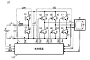
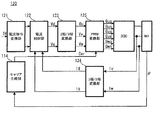
始めに、図1を参照し、本実施形態に係るモータ駆動システム10の構成について説明する。ここに、図1は、モータ駆動システム10の構成を概念的に表すシステム構成図である。
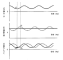
次に、図6を参照し、本実施形態の効果として、PID制御の効果について説明する。ここに、図6は、三相交流モータM1の出力電力たるモータ電力Pm、平滑コンデンサCの端子間電圧である端子間電圧VH及びバッテリBの出力電流であるバッテリ電流Ibの位相関係を説明する図である。
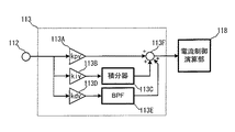
次に、図7を参照し、本実施形態の効果として、BPF113Eの効果について説明する。ここに、図7は、BPF113Eの特性を概念的に表す模式的なボード線図である。
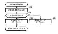
ここで、図8を参照し、ECU100により実行されるモード切替制御処理について説明する。ここに、図8は、モード切替制御処理のフローチャートである。
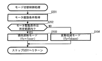
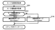
次に、図10を参照し、本発明の第2実施形態に係るモード切替制御処理について説明する。ここに、図10は、第2実施形態に係るモード切り替え制御処理のフローチャートである。尚、同図において、図8と重複する箇所には同一の符号を付してその説明を適宜省略することとする。尚、第2実施形態に係るシステム構成は、第1実施形態に係るモータ駆動システム10と同等であるとする。
Claims (5)
- 直流電源と、
三相交流モータと、
前記直流電源と前記三相交流モータとの間に設けられ、前記三相交流モータの三相各々に対応するスイッチング回路及び該スイッチング回路に対し電気的に並列に配置された平滑コンデンサを含んでなる電力変換器と、
前記電力変換器と前記直流電源との間に設置され、前記直流電源の直流電圧を昇圧して前記電力変換器に供給する昇圧コンバータと
を備えたモータ駆動システムにおいて前記昇圧コンバータを制御する昇圧コンバータの制御装置であって、
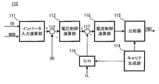
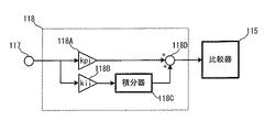
比例要素、積分要素及び微分要素を備え、且つ該微分要素が帯域通過フィルタとして構成されると共に、前記昇圧コンバータの出力電圧を前記平滑コンデンサの端子間電圧VHの指令値に維持するための前記昇圧コンバータの電流指令値に相当するPID制御量を演算する演算手段と、
前記演算されたPID制御量に基づいて前記昇圧コンバータの出力電圧を制御する制御手段と、
前記端子間電圧VHの変動抑制に対して前記直流電源における電力の入出力に伴う損失抑制を優先すべきか否かを判定する判定手段と、
前記損失抑制を優先すべき旨が判定された場合に、前記演算手段が前記PID制御量を演算するにあたっての演算モードを、前記帯域通過フィルタのカットオフ周波数が基準値に維持される変動抑制モードから、前記カットオフ周波数が前記基準値に対して減少側に補正される損失抑制モードへ切り替える切り替え手段と
を具備し、
前記損失抑制モードにおいては、前記三相交流モータの回転速度が低い程、前記カットオフ周波数が低周波側に補正される
ことを特徴とする昇圧コンバータの制御装置。 - 前記昇圧コンバータは、
前記直流電源の正極に一端が接続されるリアクトルと、
前記リアクトルの他端と前記電力変換器との間に接続される第1スイッチング素子と、
前記リアクトルの他端と前記直流電源の負極との間に接続される第2スイッチング素子と、
前記第1及び第2スイッチング素子に夫々逆並列に接続される第1及び第2ダイオードと
を含む
ことを特徴とする請求の範囲第1項に記載の昇圧コンバータの制御装置。 - 前記判定手段は、前記端子間電圧VHの変動レベルに基づいて前記損失抑制を優先すべきか否かを判定する
ことを特徴とする請求の範囲第1項に記載の昇圧コンバータの制御装置。 - 前記判定手段は、前記三相交流モータの駆動条件に基づいて前記損失抑制を優先すべきか否かを判定する
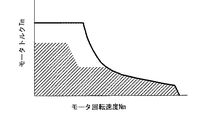
ことを特徴とする請求の範囲第1項に記載の昇圧コンバータの制御装置。 - 前記判定手段は、前記三相交流モータのトルク値が、前記三相交流モータの回転速度の高低に応じて夫々低高に変化する基準値未満である場合に、前記損失抑制を優先すべきものと判定する
ことを特徴とする請求の範囲第4項に記載の昇圧コンバータの制御装置。
Applications Claiming Priority (1)
| Application Number | Priority Date | Filing Date | Title |
|---|---|---|---|
| PCT/JP2011/059652 WO2012144019A1 (ja) | 2011-04-19 | 2011-04-19 | 昇圧コンバータの制御装置 |
Publications (2)
| Publication Number | Publication Date |
|---|---|
| JP5429403B2 JP5429403B2 (ja) | 2014-02-26 |
| JPWO2012144019A1 true JPWO2012144019A1 (ja) | 2014-07-28 |
Family
ID=47041169
Family Applications (1)
| Application Number | Title | Priority Date | Filing Date |
|---|---|---|---|
| JP2012544788A Active JP5429403B2 (ja) | 2011-04-19 | 2011-04-19 | 昇圧コンバータの制御装置 |
Country Status (5)
| Country | Link |
|---|---|
| US (1) | US8866430B2 (ja) |
| EP (1) | EP2701295B1 (ja) |
| JP (1) | JP5429403B2 (ja) |
| CN (1) | CN102859853B (ja) |
| WO (1) | WO2012144019A1 (ja) |
Families Citing this family (9)
| Publication number | Priority date | Publication date | Assignee | Title |
|---|---|---|---|---|
| EP2408103B1 (en) * | 2009-03-11 | 2017-11-22 | Mitsubishi Electric Corporation | Controller of ac rotating machine |
| JP5035641B2 (ja) * | 2009-11-30 | 2012-09-26 | アイシン・エィ・ダブリュ株式会社 | 電動機駆動装置の制御装置 |
| US20130076128A1 (en) * | 2011-09-28 | 2013-03-28 | Caterpillar, Inc. | Active Switching Frequency Modulation |
| US9649941B2 (en) * | 2013-07-11 | 2017-05-16 | Ford Global Technologies, Llc | Boost converter deadtime compensation |
| JP6488963B2 (ja) * | 2015-09-28 | 2019-03-27 | 株式会社デンソー | 電源システムの制御装置、及び電源ユニット |
| DE102016215008A1 (de) * | 2016-08-11 | 2018-02-15 | Siemens Aktiengesellschaft | Verfahren zum Betreiben eines Stromrichters sowie danach arbeitender Stromrichter |
| JP6985222B2 (ja) * | 2018-08-03 | 2021-12-22 | 日立Astemo株式会社 | 昇圧コンバータの制御装置 |
| JP7189009B2 (ja) | 2018-12-25 | 2022-12-13 | トヨタ自動車株式会社 | 車両の制御装置 |
| JP6824342B1 (ja) * | 2019-08-26 | 2021-02-03 | 三菱電機株式会社 | 電力変換装置の制御装置 |
Family Cites Families (11)
| Publication number | Priority date | Publication date | Assignee | Title |
|---|---|---|---|---|
| JPH0914265A (ja) * | 1995-06-27 | 1997-01-14 | Shinko Electric Co Ltd | 磁気軸受補償回路 |
| GB2376357B (en) * | 2001-06-09 | 2005-05-04 | 3D Instr Ltd | Power converter and method for power conversion |
| JP2004112904A (ja) * | 2002-09-18 | 2004-04-08 | Toyota Motor Corp | 電圧変換装置、電圧変換方法、電圧変換の制御をコンピュータに実行させるためのプログラムを記録したコンピュータ読取り可能な記録媒体 |
| JP2006254518A (ja) * | 2005-03-08 | 2006-09-21 | Yaskawa Electric Corp | チョッパ装置とその制御方法 |
| KR100927453B1 (ko) * | 2005-03-31 | 2009-11-19 | 도요타 지도샤(주) | 전압변환장치 및 차량 |
| JP4706324B2 (ja) * | 2005-05-10 | 2011-06-22 | トヨタ自動車株式会社 | モータ駆動システムの制御装置 |
| JP4452735B2 (ja) * | 2007-09-05 | 2010-04-21 | 本田技研工業株式会社 | 昇圧コンバータの制御装置および制御方法 |
| US7889524B2 (en) * | 2007-10-19 | 2011-02-15 | Illinois Institute Of Technology | Integrated bi-directional converter for plug-in hybrid electric vehicles |
| JP4541425B2 (ja) * | 2008-02-25 | 2010-09-08 | 本田技研工業株式会社 | Dc/dcコンバータ装置 |
| JP5206489B2 (ja) * | 2009-02-26 | 2013-06-12 | トヨタ自動車株式会社 | 電圧変換装置 |
| CN102449891B (zh) | 2009-05-27 | 2014-07-16 | 丰田自动车株式会社 | 转换器的控制装置以及具备它的电动车辆 |
-
2011
- 2011-04-19 CN CN201180018929.1A patent/CN102859853B/zh active Active
- 2011-04-19 WO PCT/JP2011/059652 patent/WO2012144019A1/ja active Application Filing
- 2011-04-19 JP JP2012544788A patent/JP5429403B2/ja active Active
- 2011-04-19 US US13/698,230 patent/US8866430B2/en active Active
- 2011-04-19 EP EP11863724.8A patent/EP2701295B1/en active Active
Also Published As
| Publication number | Publication date |
|---|---|
| WO2012144019A1 (ja) | 2012-10-26 |
| CN102859853B (zh) | 2015-03-18 |
| EP2701295B1 (en) | 2016-12-21 |
| EP2701295A4 (en) | 2015-11-25 |
| JP5429403B2 (ja) | 2014-02-26 |
| US8866430B2 (en) | 2014-10-21 |
| CN102859853A (zh) | 2013-01-02 |
| EP2701295A1 (en) | 2014-02-26 |
| US20130057188A1 (en) | 2013-03-07 |
Similar Documents
| Publication | Publication Date | Title |
|---|---|---|
| JP5637303B2 (ja) | 昇圧コンバータの制御装置 | |
| JP5429403B2 (ja) | 昇圧コンバータの制御装置 | |
| US8054031B2 (en) | Converter device, rotating electrical machine control device, and drive device | |
| JP4353304B2 (ja) | モータ駆動制御装置 | |
| JP5472475B2 (ja) | モータ駆動システムの制御装置 | |
| JP5910752B2 (ja) | 昇圧コンバータの制御装置 | |
| WO2010137128A1 (ja) | コンバータの制御装置およびそれを備える電動車両 | |
| JP2007159368A (ja) | モータ駆動システムの制御装置 | |
| JP2011223674A (ja) | コンバータの制御装置およびそれを備える電動車両 | |
| JP5281370B2 (ja) | 交流電動機の制御装置 | |
| JP6080996B1 (ja) | 電動機駆動システム | |
| JP5958400B2 (ja) | モータ駆動制御装置 | |
| JP2011167011A (ja) | Dcdcコンバータシステム | |
| JP2015201937A (ja) | 電圧変換装置 | |
| JP5407553B2 (ja) | モータ制御装置 | |
| JP2010124662A (ja) | モータ駆動システム | |
| JP6221824B2 (ja) | 電力変換器の制御装置 | |
| JP2015202018A (ja) | 電圧変換装置 | |
| JP5686110B2 (ja) | 交流電機駆動システムの制御装置 | |
| JP2014099949A (ja) | 昇圧コンバータの制御装置 | |
| JP2019110624A (ja) | 昇圧システム | |
| JP2008211926A (ja) | 電力変換装置およびその制御方法 |
Legal Events
| Date | Code | Title | Description |
|---|---|---|---|
| TRDD | Decision of grant or rejection written | ||
| A01 | Written decision to grant a patent or to grant a registration (utility model) |
Free format text: JAPANESE INTERMEDIATE CODE: A01 Effective date: 20131105 |
|
| A61 | First payment of annual fees (during grant procedure) |
Free format text: JAPANESE INTERMEDIATE CODE: A61 Effective date: 20131118 |
|
| R151 | Written notification of patent or utility model registration |
Ref document number: 5429403 Country of ref document: JP Free format text: JAPANESE INTERMEDIATE CODE: R151 |
|
| S111 | Request for change of ownership or part of ownership |
Free format text: JAPANESE INTERMEDIATE CODE: R313113 |
|
| R350 | Written notification of registration of transfer |
Free format text: JAPANESE INTERMEDIATE CODE: R350 |
|
| R250 | Receipt of annual fees |
Free format text: JAPANESE INTERMEDIATE CODE: R250 |
|
| R250 | Receipt of annual fees |
Free format text: JAPANESE INTERMEDIATE CODE: R250 |
|
| R250 | Receipt of annual fees |
Free format text: JAPANESE INTERMEDIATE CODE: R250 |
|
| R250 | Receipt of annual fees |
Free format text: JAPANESE INTERMEDIATE CODE: R250 |