JP6956728B2 - Control of wireless power transfer system - Google Patents
Control of wireless power transfer system Download PDFInfo
- Publication number
- JP6956728B2 JP6956728B2 JP2018540157A JP2018540157A JP6956728B2 JP 6956728 B2 JP6956728 B2 JP 6956728B2 JP 2018540157 A JP2018540157 A JP 2018540157A JP 2018540157 A JP2018540157 A JP 2018540157A JP 6956728 B2 JP6956728 B2 JP 6956728B2
- Authority
- JP
- Japan
- Prior art keywords
- transmitter
- reactance
- power
- receiver
- imn
- Prior art date
- Legal status (The legal status is an assumption and is not a legal conclusion. Google has not performed a legal analysis and makes no representation as to the accuracy of the status listed.)
- Active
Links
- 238000012546 transfer Methods 0.000 title claims description 69
- 238000000034 method Methods 0.000 claims description 125
- 230000008569 process Effects 0.000 claims description 116
- 238000012545 processing Methods 0.000 claims description 57
- 230000004044 response Effects 0.000 claims description 9
- 230000003213 activating effect Effects 0.000 claims description 7
- 230000010363 phase shift Effects 0.000 description 56
- 239000003990 capacitor Substances 0.000 description 28
- 238000004891 communication Methods 0.000 description 20
- 230000008859 change Effects 0.000 description 17
- 230000005540 biological transmission Effects 0.000 description 10
- 238000004590 computer program Methods 0.000 description 10
- 230000008878 coupling Effects 0.000 description 7
- 238000010168 coupling process Methods 0.000 description 7
- 238000005859 coupling reaction Methods 0.000 description 7
- 230000007423 decrease Effects 0.000 description 6
- 238000005259 measurement Methods 0.000 description 5
- 230000000694 effects Effects 0.000 description 4
- 230000007613 environmental effect Effects 0.000 description 4
- 230000006870 function Effects 0.000 description 4
- 230000006698 induction Effects 0.000 description 4
- 238000001994 activation Methods 0.000 description 3
- 230000001965 increasing effect Effects 0.000 description 3
- 230000003287 optical effect Effects 0.000 description 3
- 238000000926 separation method Methods 0.000 description 3
- 238000012937 correction Methods 0.000 description 2
- 238000013461 design Methods 0.000 description 2
- 238000010586 diagram Methods 0.000 description 2
- 230000005684 electric field Effects 0.000 description 2
- 230000001976 improved effect Effects 0.000 description 2
- 230000001939 inductive effect Effects 0.000 description 2
- 238000012544 monitoring process Methods 0.000 description 2
- 238000013515 script Methods 0.000 description 2
- 241001125929 Trisopterus luscus Species 0.000 description 1
- 230000004913 activation Effects 0.000 description 1
- 238000003491 array Methods 0.000 description 1
- 230000006399 behavior Effects 0.000 description 1
- 235000013361 beverage Nutrition 0.000 description 1
- 238000006243 chemical reaction Methods 0.000 description 1
- 230000002452 interceptive effect Effects 0.000 description 1
- 230000001902 propagating effect Effects 0.000 description 1
- 239000004065 semiconductor Substances 0.000 description 1
- 239000000126 substance Substances 0.000 description 1
Images


Classifications
-
- H—ELECTRICITY
- H02—GENERATION; CONVERSION OR DISTRIBUTION OF ELECTRIC POWER
- H02J—CIRCUIT ARRANGEMENTS OR SYSTEMS FOR SUPPLYING OR DISTRIBUTING ELECTRIC POWER; SYSTEMS FOR STORING ELECTRIC ENERGY
- H02J50/00—Circuit arrangements or systems for wireless supply or distribution of electric power
- H02J50/10—Circuit arrangements or systems for wireless supply or distribution of electric power using inductive coupling
- H02J50/12—Circuit arrangements or systems for wireless supply or distribution of electric power using inductive coupling of the resonant type
-
- B—PERFORMING OPERATIONS; TRANSPORTING
- B60—VEHICLES IN GENERAL
- B60L—PROPULSION OF ELECTRICALLY-PROPELLED VEHICLES; SUPPLYING ELECTRIC POWER FOR AUXILIARY EQUIPMENT OF ELECTRICALLY-PROPELLED VEHICLES; ELECTRODYNAMIC BRAKE SYSTEMS FOR VEHICLES IN GENERAL; MAGNETIC SUSPENSION OR LEVITATION FOR VEHICLES; MONITORING OPERATING VARIABLES OF ELECTRICALLY-PROPELLED VEHICLES; ELECTRIC SAFETY DEVICES FOR ELECTRICALLY-PROPELLED VEHICLES
- B60L53/00—Methods of charging batteries, specially adapted for electric vehicles; Charging stations or on-board charging equipment therefor; Exchange of energy storage elements in electric vehicles
- B60L53/10—Methods of charging batteries, specially adapted for electric vehicles; Charging stations or on-board charging equipment therefor; Exchange of energy storage elements in electric vehicles characterised by the energy transfer between the charging station and the vehicle
- B60L53/12—Inductive energy transfer
- B60L53/122—Circuits or methods for driving the primary coil, e.g. supplying electric power to the coil
-
- B—PERFORMING OPERATIONS; TRANSPORTING
- B60—VEHICLES IN GENERAL
- B60L—PROPULSION OF ELECTRICALLY-PROPELLED VEHICLES; SUPPLYING ELECTRIC POWER FOR AUXILIARY EQUIPMENT OF ELECTRICALLY-PROPELLED VEHICLES; ELECTRODYNAMIC BRAKE SYSTEMS FOR VEHICLES IN GENERAL; MAGNETIC SUSPENSION OR LEVITATION FOR VEHICLES; MONITORING OPERATING VARIABLES OF ELECTRICALLY-PROPELLED VEHICLES; ELECTRIC SAFETY DEVICES FOR ELECTRICALLY-PROPELLED VEHICLES
- B60L53/00—Methods of charging batteries, specially adapted for electric vehicles; Charging stations or on-board charging equipment therefor; Exchange of energy storage elements in electric vehicles
- B60L53/10—Methods of charging batteries, specially adapted for electric vehicles; Charging stations or on-board charging equipment therefor; Exchange of energy storage elements in electric vehicles characterised by the energy transfer between the charging station and the vehicle
- B60L53/12—Inductive energy transfer
- B60L53/126—Methods for pairing a vehicle and a charging station, e.g. establishing a one-to-one relation between a wireless power transmitter and a wireless power receiver
-
- B—PERFORMING OPERATIONS; TRANSPORTING
- B60—VEHICLES IN GENERAL
- B60L—PROPULSION OF ELECTRICALLY-PROPELLED VEHICLES; SUPPLYING ELECTRIC POWER FOR AUXILIARY EQUIPMENT OF ELECTRICALLY-PROPELLED VEHICLES; ELECTRODYNAMIC BRAKE SYSTEMS FOR VEHICLES IN GENERAL; MAGNETIC SUSPENSION OR LEVITATION FOR VEHICLES; MONITORING OPERATING VARIABLES OF ELECTRICALLY-PROPELLED VEHICLES; ELECTRIC SAFETY DEVICES FOR ELECTRICALLY-PROPELLED VEHICLES
- B60L53/00—Methods of charging batteries, specially adapted for electric vehicles; Charging stations or on-board charging equipment therefor; Exchange of energy storage elements in electric vehicles
- B60L53/30—Constructional details of charging stations
- B60L53/35—Means for automatic or assisted adjustment of the relative position of charging devices and vehicles
- B60L53/38—Means for automatic or assisted adjustment of the relative position of charging devices and vehicles specially adapted for charging by inductive energy transfer
- B60L53/39—Means for automatic or assisted adjustment of the relative position of charging devices and vehicles specially adapted for charging by inductive energy transfer with position-responsive activation of primary coils
-
- G—PHYSICS
- G05—CONTROLLING; REGULATING
- G05F—SYSTEMS FOR REGULATING ELECTRIC OR MAGNETIC VARIABLES
- G05F1/00—Automatic systems in which deviations of an electric quantity from one or more predetermined values are detected at the output of the system and fed back to a device within the system to restore the detected quantity to its predetermined value or values, i.e. retroactive systems
- G05F1/66—Regulating electric power
-
- H—ELECTRICITY
- H02—GENERATION; CONVERSION OR DISTRIBUTION OF ELECTRIC POWER
- H02J—CIRCUIT ARRANGEMENTS OR SYSTEMS FOR SUPPLYING OR DISTRIBUTING ELECTRIC POWER; SYSTEMS FOR STORING ELECTRIC ENERGY
- H02J50/00—Circuit arrangements or systems for wireless supply or distribution of electric power
- H02J50/80—Circuit arrangements or systems for wireless supply or distribution of electric power involving the exchange of data, concerning supply or distribution of electric power, between transmitting devices and receiving devices
-
- H—ELECTRICITY
- H02—GENERATION; CONVERSION OR DISTRIBUTION OF ELECTRIC POWER
- H02J—CIRCUIT ARRANGEMENTS OR SYSTEMS FOR SUPPLYING OR DISTRIBUTING ELECTRIC POWER; SYSTEMS FOR STORING ELECTRIC ENERGY
- H02J50/00—Circuit arrangements or systems for wireless supply or distribution of electric power
- H02J50/90—Circuit arrangements or systems for wireless supply or distribution of electric power involving detection or optimisation of position, e.g. alignment
-
- H—ELECTRICITY
- H02—GENERATION; CONVERSION OR DISTRIBUTION OF ELECTRIC POWER
- H02M—APPARATUS FOR CONVERSION BETWEEN AC AND AC, BETWEEN AC AND DC, OR BETWEEN DC AND DC, AND FOR USE WITH MAINS OR SIMILAR POWER SUPPLY SYSTEMS; CONVERSION OF DC OR AC INPUT POWER INTO SURGE OUTPUT POWER; CONTROL OR REGULATION THEREOF
- H02M3/00—Conversion of dc power input into dc power output
- H02M3/22—Conversion of dc power input into dc power output with intermediate conversion into ac
- H02M3/24—Conversion of dc power input into dc power output with intermediate conversion into ac by static converters
-
- H—ELECTRICITY
- H03—ELECTRONIC CIRCUITRY
- H03H—IMPEDANCE NETWORKS, e.g. RESONANT CIRCUITS; RESONATORS
- H03H7/00—Multiple-port networks comprising only passive electrical elements as network components
- H03H7/38—Impedance-matching networks
-
- H—ELECTRICITY
- H03—ELECTRONIC CIRCUITRY
- H03H—IMPEDANCE NETWORKS, e.g. RESONANT CIRCUITS; RESONATORS
- H03H7/00—Multiple-port networks comprising only passive electrical elements as network components
- H03H7/38—Impedance-matching networks
- H03H7/383—Impedance-matching networks comprising distributed impedance elements together with lumped impedance elements
-
- H—ELECTRICITY
- H03—ELECTRONIC CIRCUITRY
- H03H—IMPEDANCE NETWORKS, e.g. RESONANT CIRCUITS; RESONATORS
- H03H7/00—Multiple-port networks comprising only passive electrical elements as network components
- H03H7/38—Impedance-matching networks
- H03H7/40—Automatic matching of load impedance to source impedance
-
- H04B5/24—
-
- H04B5/79—
-
- Y—GENERAL TAGGING OF NEW TECHNOLOGICAL DEVELOPMENTS; GENERAL TAGGING OF CROSS-SECTIONAL TECHNOLOGIES SPANNING OVER SEVERAL SECTIONS OF THE IPC; TECHNICAL SUBJECTS COVERED BY FORMER USPC CROSS-REFERENCE ART COLLECTIONS [XRACs] AND DIGESTS
- Y02—TECHNOLOGIES OR APPLICATIONS FOR MITIGATION OR ADAPTATION AGAINST CLIMATE CHANGE
- Y02T—CLIMATE CHANGE MITIGATION TECHNOLOGIES RELATED TO TRANSPORTATION
- Y02T10/00—Road transport of goods or passengers
- Y02T10/60—Other road transportation technologies with climate change mitigation effect
- Y02T10/70—Energy storage systems for electromobility, e.g. batteries
-
- Y—GENERAL TAGGING OF NEW TECHNOLOGICAL DEVELOPMENTS; GENERAL TAGGING OF CROSS-SECTIONAL TECHNOLOGIES SPANNING OVER SEVERAL SECTIONS OF THE IPC; TECHNICAL SUBJECTS COVERED BY FORMER USPC CROSS-REFERENCE ART COLLECTIONS [XRACs] AND DIGESTS
- Y02—TECHNOLOGIES OR APPLICATIONS FOR MITIGATION OR ADAPTATION AGAINST CLIMATE CHANGE
- Y02T—CLIMATE CHANGE MITIGATION TECHNOLOGIES RELATED TO TRANSPORTATION
- Y02T10/00—Road transport of goods or passengers
- Y02T10/60—Other road transportation technologies with climate change mitigation effect
- Y02T10/7072—Electromobility specific charging systems or methods for batteries, ultracapacitors, supercapacitors or double-layer capacitors
-
- Y—GENERAL TAGGING OF NEW TECHNOLOGICAL DEVELOPMENTS; GENERAL TAGGING OF CROSS-SECTIONAL TECHNOLOGIES SPANNING OVER SEVERAL SECTIONS OF THE IPC; TECHNICAL SUBJECTS COVERED BY FORMER USPC CROSS-REFERENCE ART COLLECTIONS [XRACs] AND DIGESTS
- Y02—TECHNOLOGIES OR APPLICATIONS FOR MITIGATION OR ADAPTATION AGAINST CLIMATE CHANGE
- Y02T—CLIMATE CHANGE MITIGATION TECHNOLOGIES RELATED TO TRANSPORTATION
- Y02T90/00—Enabling technologies or technologies with a potential or indirect contribution to GHG emissions mitigation
- Y02T90/10—Technologies relating to charging of electric vehicles
- Y02T90/12—Electric charging stations
-
- Y—GENERAL TAGGING OF NEW TECHNOLOGICAL DEVELOPMENTS; GENERAL TAGGING OF CROSS-SECTIONAL TECHNOLOGIES SPANNING OVER SEVERAL SECTIONS OF THE IPC; TECHNICAL SUBJECTS COVERED BY FORMER USPC CROSS-REFERENCE ART COLLECTIONS [XRACs] AND DIGESTS
- Y02—TECHNOLOGIES OR APPLICATIONS FOR MITIGATION OR ADAPTATION AGAINST CLIMATE CHANGE
- Y02T—CLIMATE CHANGE MITIGATION TECHNOLOGIES RELATED TO TRANSPORTATION
- Y02T90/00—Enabling technologies or technologies with a potential or indirect contribution to GHG emissions mitigation
- Y02T90/10—Technologies relating to charging of electric vehicles
- Y02T90/14—Plug-in electric vehicles
Description
本出願は、2016年2月2日に出願された米国仮特許出願番号62/290,325号、及び2016年8月25日に出願された米国仮特許出願番号62/379,618号の優先権を主張するものであり、これらの先行出願の内容は、参照により本明細書に組み込まれる。 This application is prioritized by US Provisional Patent Application No. 62 / 290,325 filed on February 2, 2016, and US Provisional Patent Application No. 62 / 379,618 filed on August 25, 2016. Priority is claimed and the content of these prior applications is incorporated herein by reference.
ワイヤレス電力伝送システムは、多岐に渡る結合係数k、負荷条件、及び環境条件において動作する。これらのパラメータの変化はワイヤレス電力伝送システムの効率に影響する。ワイヤレス電力伝送システムは、電力伝送の性能及び効率を向上させるためのインピーダンスマッチングネットワークを含むことができる。このような多岐に渡る条件において、ワイヤレス電力伝送システムの良好な性能を得ることは、従来のインピーダンスマッチングネットワークにおける課題である。 Wireless power transfer systems operate under a wide variety of coupling coefficients k, load and environmental conditions. Changes in these parameters affect the efficiency of wireless power transfer systems. Wireless power transfer systems can include impedance matching networks to improve the performance and efficiency of power transfer. Under such a wide variety of conditions, obtaining good performance of a wireless power transmission system is a problem in a conventional impedance matching network.
一般に、本開示は、システム、パラメータ、環境パラメータ、又はその両方の変化に適応するように、ワイヤレス電力送信機及び受信機を同期的にチューニングするワイヤレス電力伝送制御システムを特徴とする。本明細書に記載のワイヤレス電力伝送制御システムは、組み込み装置、携帯電話及び他のモバイルの電子機器の充電器、並びに電気自動車用の充電器を含む、様々な状況で使用され得る。 In general, the disclosure features a wireless power transfer control system that synchronously tunes wireless power transmitters and receivers to adapt to changes in systems, parameters, environmental parameters, or both. The wireless power transfer control systems described herein can be used in a variety of situations, including chargers for embedded devices, mobile phones and other mobile electronic devices, and chargers for electric vehicles.
第1の態様では、本開示は、送信機インピーダンスマッチングネットワーク(IMN)を有するワイヤレス電力送信機を特徴とする。送信機は、送信機の電力の特性と目標電力との第1の比較を実行することを含む処理を実行するように構成される。第1の比較に基づいて、送信機IMNのリアクタンスを調整して、送信機の電力が調整される。送信機の電力を示す電力データがワイヤレス電力受信機に送信される。 In a first aspect, the disclosure features a wireless power transmitter having a transmitter impedance matching network (IMN). The transmitter is configured to perform processing, including performing a first comparison between the power characteristics of the transmitter and the target power. Based on the first comparison, the reactance of the transmitter IMN is adjusted to adjust the power of the transmitter. Power data indicating the power of the transmitter is transmitted to the wireless power receiver.
第2の態様では、本開示は、受信機IMNを有するワイヤレス電力受信機を特徴とする。受信機は、ワイヤレス電力送信機からの電力データに基づいて、第2の時間における、ワイヤレス電力伝送システムの効率を判定することを含む処理を実行するように構成される。第2の時間における効率と、第2の時間よりも前の、第1の時間におけるワイヤレス電力伝送システムの効率との第2の比較が実行される。第2の比較に基づいて、受信機IMNのリアクタンスが調整される。 In a second aspect, the disclosure features a wireless power receiver with a receiver IMN. The receiver is configured to perform processing, including determining the efficiency of the wireless power transfer system in a second time, based on the power data from the wireless power transmitter. A second comparison is made between the efficiency in the second time and the efficiency of the wireless power transfer system in the first time prior to the second time. Based on the second comparison, the reactance of the receiver IMN is adjusted.
第3の態様では、本開示は、電力送信機と電力受信機とを含む、ワイヤレス電力伝送システムを特徴とする。送信機は、送信機IMNを有する。送信機は、送信機の電力の特性と目標電力との第1の比較を実行することを含む処理を実行するように構成される。第1の比較に基づいて、送信機IMNのリアクタンスを調整して、送信機の電力が調整される。受信機は受信機IMNを有する。受信機は、送信機からの電力データに基づいて、第2の時間における、ワイヤレス電力伝送システムの効率を判定することを含む処理を実行するように構成される。第2の時間における効率と、第2の時間よりも前の、第1の時間におけるワイヤレス電力伝送システムの効率との第2の比較が実行される。第2の比較に基づいて、受信機IMNのリアクタンスが調整される。 In a third aspect, the disclosure features a wireless power transfer system that includes a power transmitter and a power receiver. The transmitter has a transmitter IMN. The transmitter is configured to perform processing, including performing a first comparison between the power characteristics of the transmitter and the target power. Based on the first comparison, the reactance of the transmitter IMN is adjusted to adjust the power of the transmitter. The receiver has a receiver IMN. The receiver is configured to perform processing, including determining the efficiency of the wireless power transfer system in a second time, based on the power data from the transmitter. A second comparison is made between the efficiency in the second time and the efficiency of the wireless power transfer system in the first time prior to the second time. Based on the second comparison, the reactance of the receiver IMN is adjusted.
第1の態様及び第2の態様は、第3の態様のシステムなどのシステムにおいて、協働することができる。更に、これら及び第4の態様から第7の態様は、各々、以下の特徴の1つ以上を任意に含み得る。 The first aspect and the second aspect can cooperate in a system such as the system of the third aspect. Further, each of these and the fourth to seventh aspects may optionally include one or more of the following features.
ある実装では、受信機IMNのリアクタンスを調整することには、可変リアクタンス調整値で、受信機IMNのリアクタンスを調整することが含まれる。 In one implementation, adjusting the reactance of the receiver IMN involves adjusting the reactance of the receiver IMN with a variable reactance adjustment value.
ある実装では、第1の比較及び、送信機IMNのリアクタンスに対する調整は、電力の特性が目標電力の閾値内に入るまで、反復して行われる。 In some implementations, the first comparison and adjustment to the reactance of the transmitter IMN is repeated until the power characteristics fall within the target power threshold.
ある実装では、受信機IMNのリアクタンスを調整することには、第2の時間における効率が、第1の時間における効率よりも低いことに応答して、リアクタンス調整値を無効化することが含まれる。受信機IMNのリアクタンスを調整することには、無効化されたリアクタンス調整値で、受信機IMNのリアクタンスを調整することが含まれる。 In one implementation, adjusting the reactance of the receiver IMN involves invalidating the reactance adjustment value in response to the efficiency in the second time being lower than the efficiency in the first time. .. Adjusting the reactance of the receiver IMN includes adjusting the reactance of the receiver IMN with an invalidated reactance adjustment value.
ある実装では、送信機IMNのリアクタンスを調整することには、電力が目標電力より小さいことに応答して、第1のリアクタンス調整値で、送信機IMNのリアクタンスを調整することが含まれる。電力が目標電力よりも大きいことに応答して、別の第2のリアクタンス調整値で、送信機IMNのリアクタンスを調整する。 In one implementation, adjusting the reactance of the transmitter IMN involves adjusting the reactance of the transmitter IMN with a first reactance adjustment value in response to the power being less than the target power. In response to the power being greater than the target power, the reactance of the transmitter IMN is adjusted with another second reactance adjustment value.
ある実装では、第1のリアクタンス調整値は、第2のリアクタンス調整値と、大きさが等しく、符号が反対である。 In one implementation, the first reactance adjustment value is of equal magnitude and opposite sign to the second reactance adjustment value.
ある実装では、第1の比較は、送信機の電力の力率と目標力率との比較である。送信機の処理は、電力の大きさと目標電力の大きさとの第3の比較を含み、第3の比較は第1の比較に後続し、第3の比較に基づいて、送信機のバス電圧を調整して、送信機の電力が調整される。 In one implementation, the first comparison is the comparison of the power factor of the transmitter power with the target power factor. The processing of the transmitter includes a third comparison between the magnitude of the power and the magnitude of the target power, the third comparison follows the first comparison, and based on the third comparison, the bus voltage of the transmitter is calculated. Adjust to adjust the power of the transmitter.
ある実装では、力率は、送信機電圧と送信機電流との間の位相関係によって表される。 In some implementations, the power factor is represented by the phase relationship between the transmitter voltage and the transmitter current.
ある実装では、第1の比較、及び第1の比較に基づく送信機IMNのリアクタンスの調整は、電力の力率が目標力率の閾値内に入るまで、反復して行われる。 In some implementations, the first comparison and the reactance adjustment of the transmitter IMN based on the first comparison are repeated until the power factor of the power falls within the threshold of the target power factor.
ある実装では、第1の比較を実行すること、及び送信機IMNのリアクタンスを調整することは、第3の比較を実行すること、及びバス電圧を調整することよりも、速いレートで反復される。 In some implementations, performing the first comparison and adjusting the reactance of the transmitter IMN is repeated at a faster rate than performing the third comparison and adjusting the bus voltage. ..
ある実装では、送信機は電気自動車の充電器であって、受信機は電気自動車の電力システムに結合される。 In one implementation, the transmitter is an electric vehicle charger and the receiver is coupled to the electric vehicle's power system.
ある実装では、送信機の処理には、目標電力をゼロに低減することによって、ワイヤレス電力伝送システムをシャットダウンすることが含まれる。 In one implementation, transmitter processing involves shutting down a wireless power transfer system by reducing the target power to zero.
ある実装では、送信機の処理には、送信機の電力インバータをシャットダウンすることが含まれる。 In some implementations, transmitter processing involves shutting down the transmitter's power inverter.
ある実装では、送信機の処理には、送信機IMNのリアクタンスを最大値に調整することによって、送信機を起動することが含まれる。 In one implementation, transmitter processing involves activating the transmitter by adjusting the reactance of the transmitter IMN to a maximum value.
ある実装では、送信機の処理には、インバータの周波数を目標周波数に調整することによって、送信機を起動することが含まれる。 In one implementation, transmitter processing involves activating the transmitter by adjusting the frequency of the inverter to a target frequency.
ある実装では、受信機の処理には、受信機IMNのリアクタンスを最小値に調整することによって受信機を起動することが含まれる。 In one implementation, receiver processing involves activating the receiver by adjusting the reactance of the receiver IMN to a minimum value.
ある実装では、受信機の処理には、受信機IMNのリアクタンスを最大値から最小値に調整することによって、受信機を起動することが含まれる。 In one implementation, receiver processing involves activating the receiver by adjusting the reactance of the receiver IMN from a maximum value to a minimum value.
ある実装では、送信機IMNは、インバータと、少なくとも1つの固定リアクタンス素子との間に電気的に接続された、チューニング可能なリアクタンス素子を備え、送信機IMNのリアクタンスを調整することには、チューニング可能なリアクタンス素子を調整することが含まれる。 In one implementation, the transmitter IMN comprises a tunable reactance element that is electrically connected between the inverter and at least one fixed reactance element, and is tuned to adjust the reactance of the transmitter IMN. It involves adjusting the possible reactance elements.
ある実装では、受信機IMNは、整流器と、少なくとも1つの固定リアクタンス素子との間に電気的に接続された、チューニング可能なリアクタンス素子を備え、受信機IMNのリアクタンスを調整することには、チューニング可能なリアクタンス素子を調整することが含まれる。 In one implementation, the receiver IMN comprises a tunable reactance element that is electrically connected between the rectifier and at least one fixed reactance element and is tuned to adjust the reactance of the receiver IMN. It involves adjusting the reactance elements that are possible.
ある実装では、第1の比較を実行すること、及び送信機IMNのリアクタンスを調整することは、第2の比較を実行すること、及び受信機IMNのリアクタンスを調整することよりも、速いレートで反復される。 In some implementations, performing the first comparison and adjusting the reactance of the transmitter IMN is faster than performing the second comparison and adjusting the reactance of the receiver IMN. It repeats.
ある実装では、ワイヤレス電力伝送システムの効率を判定することには、送信機から電力データを受信すること、受信機の出力電力を判定すること、及び送信機からの電力データと、受信機の出力電力とに基づいて、ワイヤレス電力伝送システムの効率を計算することが含まれる。 In one implementation, determining the efficiency of a wireless power transmission system is to receive power data from the transmitter, determine the output power of the receiver, and the power data from the transmitter and the output of the receiver. Includes calculating the efficiency of wireless power transmission systems based on power.
ある実装では、送信機の処理には、電力の大きさのチェック、電力の力率のチェック、及び、送信機のインバータの周波数のチェックを含み得る、複数のチェックを実行することと、複数のチェックに応答して、選択的にインバータの周波数を調整して、送信機の電力を調整することが、含まれる。 In some implementations, transmitter processing may include performing multiple checks, including checking power magnitude, power factor, and frequency of the transmitter's inverter. In response to the check, selectively adjusting the frequency of the inverter to adjust the power of the transmitter is included.
ある実装では、送信機の処理には、電力の大きさのチェック、及び送信機のインバータの位相シフトのチェックを含み得る、複数のチェックを実行することと、複数のチェックに応答して、選択的にインバータの位相シフトを調整して、送信機の電力を調整することが、含まれる。 In some implementations, transmitter processing may include checking the magnitude of power and checking the phase shift of the transmitter's inverter, performing multiple checks and selecting in response to multiple checks. This includes adjusting the phase shift of the inverter to adjust the power of the transmitter.
ある実装では、送信機の処理には、バス電圧を調整する前に、バス電圧が最小バス電圧よりも大きいことを検証することが含まれる。 In some implementations, transmitter processing involves verifying that the bus voltage is greater than the minimum bus voltage before adjusting the bus voltage.
ある実装では、第1の比較は、送信機の電力の力率と目標力率との比較である。送信機の処理には、電力の大きさと目標電力の大きさとの第3の比較を実行することと、第3の比較に基づいて、送信機のIMNのリアクタンスを調整して、送信機の電力を低減することが、含まれ得る。 In one implementation, the first comparison is the comparison of the power factor of the transmitter power with the target power factor. For transmitter processing, a third comparison is made between the magnitude of the power and the magnitude of the target power, and based on the third comparison, the reactance of the transmitter's IMN is adjusted to power the transmitter. May be included.
ある実装では、第1の比較は、送信機の電力の力率と目標力率との比較である。送信機の処理には、電力の大きさと目標電力の大きさとの第3の比較を実行することと、第3の比較に基づいて、送信機のインバータの周波数を調整して、送信機の電力を低減することが、含まれ得る。 In one implementation, the first comparison is the comparison of the power factor of the transmitter power with the target power factor. To process the transmitter, perform a third comparison between the magnitude of the power and the magnitude of the target power, and based on the third comparison, adjust the frequency of the inverter of the transmitter to power the transmitter. May be included.
ある実装では、第1の比較は、送信機の電力の力率と目標力率との比較である。送信機の処理には、電力の大きさと目標電力の大きさとの第3の比較を実行することと、第3の比較に基づいて、送信機のインバータの位相シフトを調整して、送信機の電力を低減することが、含まれ得る。 In one implementation, the first comparison is the comparison of the power factor of the transmitter power with the target power factor. In the processing of the transmitter, a third comparison between the magnitude of the power and the magnitude of the target power is performed, and based on the third comparison, the phase shift of the inverter of the transmitter is adjusted to adjust the phase shift of the transmitter. Reducing power can be included.
ある実装では、送信機は、送信機インピーダンスマッチングネットワークの少なくとも一部に結合されて、送信機の共振器を形成する、誘導コイルを備える。 In some implementations, the transmitter comprises an induction coil that is coupled to at least a portion of the transmitter impedance matching network to form the transmitter resonator.
ある実装では、受信機は、受信機インピーダンスマッチングネットワークの少なくとも一部に結合されて、受信機の共振器を形成する、誘導コイルを備える。 In one implementation, the receiver comprises an induction coil that is coupled to at least a portion of the receiver impedance matching network to form the resonator of the receiver.
第4の態様では、本開示は、本明細書に記載された主題が方法として実装され得ることを特徴とし、方法には、ワイヤレス電力送信機によって、ワイヤレス電力送信機の送信機IMNをチューニングして、目標送信機電力特性を達成する処理が含まれる。ワイヤレス電力送信機によって、送信機の電力を示す電力データが、ワイヤレス電力受信機に送信される。ワイヤレス電力受信機によって、電力データに基づいて、受信機IMNをチューニングして、ワイヤレス電力伝送システムの効率が向上させる。 In a fourth aspect, the disclosure is characterized in that the subject matter described herein can be implemented as a method, in which the transmitter IMN of a wireless power transmitter is tuned by a wireless power transmitter. It includes processing to achieve the target transmitter power characteristics. The wireless power transmitter transmits power data indicating the power of the transmitter to the wireless power receiver. The wireless power receiver tunes the receiver IMN based on the power data to improve the efficiency of the wireless power transfer system.
第5の態様では、本開示は、送信機IMNを備える、ワイヤレス電力送信機を特徴とする。送信機は、送信機IMNをチューニングして、目標送信機電力特性を達成することと、送信機の電力を示す電力データをワイヤレス電力受信機に送信することが含まれる処理を実行するように構成される。 In a fifth aspect, the disclosure features a wireless power transmitter with a transmitter IMN. The transmitter is configured to tune the transmitter IMN to perform processes that include achieving the target transmitter power characteristics and transmitting power data indicating the transmitter power to the wireless power receiver. Will be done.
第6の態様では、本開示は、受信機IMNを備える、ワイヤレス電力受信機を特徴とする。受信機は、受信機IMNをチューニングして、ワイヤレス電力送信機から受信した電力データに基づいて、ワイヤレス電力伝送システムの効率を向上させることが含まれる処理を実行するように構成される。 In a sixth aspect, the disclosure features a wireless power receiver with a receiver IMN. The receiver is configured to tune the receiver IMN to perform processes that include improving the efficiency of the wireless power transfer system based on the power data received from the wireless power transmitter.
第7の態様では、本開示は、電力送信機及び電力受信機を含む、ワイヤレス電力伝送システムを特徴とする。送信機は、送信機IMNをチューニングして、目標送信機電力特性を達成することと、送信機の電力を示す電力データを、ワイヤレス電力受信機に送信することを含む処理を実行するように構成される。受信機は、受信機IMNを備える。受信機は、ワイヤレス電力送信機から受信した電力データに基づいて、受信機IMNをチューニングして、ワイヤレス電力伝送システムの効率を向上させることを含む処理を実行するように構成される。 In a seventh aspect, the disclosure features a wireless power transfer system that includes a power transmitter and a power receiver. The transmitter is configured to tune the transmitter IMN to perform processes, including achieving the target transmitter power characteristics and transmitting power data indicating the transmitter power to the wireless power receiver. Will be done. The receiver includes a receiver IMN. The receiver is configured to perform processes including tuning the receiver IMN based on the power data received from the wireless power transmitter to improve the efficiency of the wireless power transfer system.
第5の態様及び第6の態様は、第7の態様のシステムなどのシステムにおいて、協働することができる。更に、これら及び第1の態様から第3の態様は、各々、以下の特徴の1つ以上を任意に含み得る。 The fifth aspect and the sixth aspect can cooperate in a system such as the system of the seventh aspect. Further, each of these and the first to third aspects may optionally include one or more of the following features.
ある実装では、目標送信機電力特性は目標電力係数であり、目標送信機電力特性は目標電力係数である。 In one implementation, the target transmitter power characteristic is the target power factor and the target transmitter power characteristic is the target power factor.
ある実装では、力率は、送信機電圧と送信機電流との間の位相差によって表され、目標力率は目標位相差である。 In some implementations, the power factor is represented by the phase difference between the transmitter voltage and the transmitter current, and the target power factor is the target phase difference.
ある実装では、処理には、送信機によって、インバータのバス電圧を調整して、目標電力の大きさを達成することが含まれる。 In some implementations, processing involves adjusting the bus voltage of the inverter with a transmitter to achieve a target power magnitude.
ある実装では、処理には、送信機によって、インバータのバス電圧を調整して、目標電力の大きさを達成することが含まれる。 In some implementations, processing involves adjusting the bus voltage of the inverter with a transmitter to achieve a target power magnitude.
ある実装では、処理には、送信機IMNを調整する前に、安全チェックを実行することが含まれる。また、ある実装では、安全チェックは、過電圧チェック又は過電流チェックである。 In some implementations, the process involves performing a safety check before adjusting the transmitter IMN. Also, in some implementations, the safety check is an overvoltage check or an overcurrent check.
ある実装では、処理には、送信機によって、送信機電力の大きさのチェック、送信機力率のチェック、及びインバータの周波数のチェックを含み得る、複数のチェックを実行することと、複数のチェックに応答して、選択的にインバータの周波数を調整して、送信機の電力を調整することが、含まれる。 In some implementations, processing may include performing multiple checks and multiple checks, depending on the transmitter, which may include a transmitter power factor check, a transmitter power factor check, and an inverter frequency check. In response to, selectively adjusting the frequency of the inverter to adjust the power of the transmitter is included.
ある実装では、処理には、送信機電力の大きさのチェック、及び送信機のインバータの位相シフトのチェックを含み得る、複数のチェックを実行することと、複数のチェックに応答して、選択的にインバータの位相シフトを調整して、送信機の電力を調整することが、含まれる。 In some implementations, processing may include checking the magnitude of transmitter power and checking the phase shift of the inverter's inverter, performing multiple checks and selectively responding to multiple checks. Includes adjusting the phase shift of the inverter to adjust the power of the transmitter.
ある実装では、送信機は電気自動車の充電器であって、受信機は電気自動車の電力システムに結合されている。 In one implementation, the transmitter is an electric vehicle charger and the receiver is coupled to the electric vehicle's power system.
ある実装では、処理には、送信機の起動中に、送信機IMNのリアクタンスを最大値に調整することが含まれる。 In one implementation, processing involves adjusting the reactance of the transmitter IMN to a maximum value during transmitter startup.
ある実装では、処理には、受信機の起動中に、受信機IMNのリアクタンスを最小値に調整することが含まれる。 In one implementation, the process involves adjusting the reactance of the receiver IMN to a minimum value during the activation of the receiver.
ある実装では、送信機は、送信機インピーダンスマッチングネットワークの少なくとも一部に結合されて送信機の共振器を形成する、誘導コイルを含む。 In some implementations, the transmitter includes an induction coil that is coupled to at least a portion of the transmitter impedance matching network to form a transmitter resonator.
ある実装では、受信機は、受信機インピーダンスマッチングネットワークの少なくとも一部に結合されて受信機の共振器を形成する、誘導コイルを含む。 In one implementation, the receiver includes an induction coil that is coupled to at least a portion of the receiver impedance matching network to form the resonator of the receiver.
第8の態様では、本開示は、電力伝送をチューニングするための制御ループを実施するように構成された、バス電圧制御を有さないワイヤレス電力伝送システムを特徴とする。制御ループは、ワイヤレス電力伝送システムの送信機の出力電力を制御する第1のサブループと、タンク回路をワイヤレス電力伝送システムの受信機の整流器に結合する、インダクタとキャパシタとの、合成リアクタンスをチューニングする第2のサブループとを含み、第2のサブループは、ワイヤレス電力伝送の効率を監視することによって、合成リアクタンスをチューニングする。更に、本実装及び他の実装は、それぞれ、以下の特徴の1つ以上を任意に含み得る。 In an eighth aspect, the disclosure features a wireless power transfer system without bus voltage control configured to implement a control loop for tuning power transfer. The control loop tunes the combined reactance of the inductor and capacitor, which couples the tank circuit to the rectifier of the receiver of the wireless power transfer system with the first subloop that controls the output power of the transmitter of the wireless power transfer system. A second subloop, including a second subloop, tunes the synthetic reactance by monitoring the efficiency of wireless power transfer. Further, this implementation and other implementations may optionally include one or more of the following features, respectively.
ある実装では、第2のサブループは、摂動観測(perturb-and-observe)ストラテジを使用して、タンク回路をワイヤレス電力伝送システムの受信機の整流器に結合する、インダクタとキャパシタとの、合成リアクタンスをチューニングすることによって、前のポイントに基づいて効率を向上させる。 In one implementation, the second subloop uses a perturb-and-observe strategy to couple the combined reactance of the inductor and capacitor, coupling the tank circuit to the rectifier of the receiver of a wireless power transfer system. By tuning, improve efficiency based on previous points.
ある実装では、第2のサブループは、出力電力が制御ループの開始時点の目標電力と比較される、電力比較に依存する。 In some implementations, the second subloop relies on a power comparison, where the output power is compared to the target power at the start of the control loop.
ある実装では、第2のサブループは、例えば40Hzの通信速度で動作する。 In some implementations, the second subloop operates at a communication speed of, for example, 40 Hz.
ある実装では、制御ループは、

式(1)
で特徴付けられる。ここで、Pinvは、ワイヤレス電力伝送システムの送信機のインバータからの電力で、Vbusは、バス電圧で、Rinvは、インバータから見た抵抗で、Xinvは、インバータから見たリアクタンスであって、チューニングは、Xinvが、インダクタとキャパシタとの合成リアクタンスと等しい場合に、行われる。
In some implementations, the control loop
Equation (1)
Characterized by. Here, P inv is the power from the inverter of the transmitter of the wireless power transmission system, V bus is the bus voltage, R inv is the resistance seen from the inverter, and X inv is the reactance seen from the inverter. Therefore, tuning is performed when the X inv is equal to the combined reactance of the inductor and the capacitor.
ある実装では、第1のサブループは、ワイヤレス電力送信システムの他の部分と通信しないローカルループである。 In some implementations, the first subloop is a local loop that does not communicate with other parts of the wireless power transfer system.
ある実装では、第1のサブループは、第2のサブループよりも速く、第1のサブループは、1〜10kHzのオーダーである。 In some implementations, the first subloop is faster than the second subloop and the first subloop is on the order of 1-10 kHz.
ある実装では、制御ループには、送信機リアクタンスを最大値に設定することと、受信機リアクタンスを最小値に設定することを含む、入力を準備することが含まれ、時間ゼロでのワイヤレス電力送信の効率は0であって、受信機リアクタンスは定数値又は変数値で変更され得る。 In one implementation, the control loop involves preparing the input, including setting the transmitter reactance to the maximum value and the receiver reactance to the minimum value, and wireless power transmission at zero time. The efficiency of is 0, and the reactance of the receiver can be changed by a constant value or a variable value.
ある実装では、制御ループは、出力電力を目標電力と比較することによって開始する。また、ある実装では、出力電力が目標電力の許容誤差の範囲内にある場合に、時間nにおいて効率が測定され、時間nにおける効率は、前の時間n−1における効率と比較され、時間nにおける効率が前の時間n−1における効率よりも大きいとき、受信機リアクタンスの変化が受信機リアクタンスに加えられ、出力電力は目標電力と比較される。時間nにおける効率が前の時間n−1における効率よりも小さい又は等しいとき、受信機のリアクタンスの変化は無効化され、無効化された変化は受信機のリアクタンスに加えられ、出力電力は目標電力と比較される。 In some implementations, the control loop begins by comparing the output power to the target power. Also, in one implementation, when the output power is within the tolerance of the target power, the efficiency is measured at time n, the efficiency at time n is compared to the efficiency at the previous time n-1, and the time n When the efficiency in is greater than the efficiency in the previous time n-1, a change in receiver reactance is applied to the receiver reactance and the output power is compared to the target power. When the efficiency at time n is less than or equal to the efficiency at the previous time n-1, the change in reactance of the receiver is invalidated, the invalidated change is added to the reactance of the receiver, and the output power is the target power. Is compared with.
ある実装では、出力電力が目標電力の許容誤差の範囲内にない場合、出力電力が目標電力よりも小さいか否かが判定され、出力電力が目標電力よりも小さいとき、送信機リアクタンスの変化は−δに設定され、送信機リアクタンスの変化が送信機リアクタンスに加えられ、出力電力は目標電力と比較される。出力電力が目標電力よりも大きいとき、送信機リアクタンスの変化はδに設定され、送信機リアクタンスの変化が送信機リアクタンスに加えられ、出力電力が目標電力と比較される。 In one implementation, if the output power is not within the target power tolerance, it is determined whether the output power is less than the target power, and if the output power is less than the target power, the change in transmitter reactorance is. Set to −δ, changes in transmitter reactorance are applied to transmitter reactorance and the output power is compared to the target power. When the output power is greater than the target power, the change in transmitter reactance is set to δ, the change in transmitter reactance is added to the transmitter reactance, and the output power is compared with the target power.
第9の態様では、本開示は、電力伝送をチューニングするための制御ループを実装するように構成された、バス電圧制御を有するワイヤレス電力伝送システムを特徴とする。制御ループは、
で定義されるように位相を制御する、第1のサブループと、出力電力を制御する、第2のサブループと、効率を監視することによって、タンク回路をワイヤレス電力伝送システムの受信機の整流器に結合する、インダクタとキャパシタとの、合成リアクタンスをチューニングする、第3のサブループと、を含む。
更に、本実装及び他の実装は、それぞれ、以下の特徴の1つ以上を任意に含み得る。
In a ninth aspect, the disclosure features a wireless power transfer system with bus voltage control configured to implement a control loop for tuning power transfer. The control loop is
The tank circuit is coupled to the receiver rectifier of the wireless power transfer system by monitoring the efficiency of the first subloop, which controls the phase, and the second subloop, which controls the output power, as defined in. A third subloop, which tunes the combined reactance of the inductor and the capacitor, is included.
Further, this implementation and other implementations may optionally include one or more of the following features, respectively.
ある実装では、第3のサブループは、摂動観測ストラテジを使用して、インダクタとキャパシタとの合成リアクタンスをチューニングすることによって、前のポイントに基づいて効率を向上させる。 In some implementations, a third subloop uses a perturbation observation strategy to tune the synthetic reactance between the inductor and the capacitor to improve efficiency based on previous points.
ある実装では、第3のサブループは、電力比較に依存し、第2のサブループに依存する。 In some implementations, the third subloop depends on the power comparison and the second subloop.
ある実装では、第3のサブループは、例えば40Hzの通信速度(WiFiの速度)で動作する。 In some implementations, the third subloop operates at, for example, a communication speed of 40 Hz (WiFi speed).
ある実装では、制御ループは、
式(3)
で特徴付けられる。ここで、Pinvは、ワイヤレス電力伝送システムの送信機のインバータからの電力の出力で、Vbusは、バス電圧で、Rinvは、インバータから見た抵抗で、Xinvは、インバータから見たリアクタンスであって、チューニングは、Vbus及びX3=Xinvにおいて、行われる。
In some implementations, the control loop
Equation (3)
Characterized by. Here, the P inv, the power output of the inverter of the transmitter of the wireless power transmission system, V bus is a bus voltage, R inv is the saw from the inverter resistance, X inv is viewed from the inverter Reactance, tuning is done at V bus and X3 = X inverter .
ある実装では、第1のサブループがまず調整され、第2のサブループが次に調整され、第3のサブループが続いて調整される。 In some implementations, the first subloop is adjusted first, the second subloop is adjusted next, and the third subloop is subsequently adjusted.
ある実装では、第1のサブループは、1〜10kHzのオーダーで動作する。 In some implementations, the first subloop operates on the order of 1-10 kHz.
ある実装では、第1のサブループはローカルループであって、ワイヤレス電力伝送システムの他の部分と通信しない。 In some implementations, the first subloop is a local loop that does not communicate with other parts of the wireless power transfer system.
ある実装では、第2のサブループはローカルループであり、ワイヤレス電力伝送システムの他の部分と通信しない。 In some implementations, the second subloop is a local loop that does not communicate with other parts of the wireless power transfer system.
ある実装では、第2のサブループは、1〜10kHzのオーダーで動作する。 In some implementations, the second subloop operates on the order of 1-10 kHz.
ある実装では、制御ループには、送信機リアクタンスを最大値に設定することと、受信機リアクタンスを最小値に設定することを含む、入力を準備することが含まれ、時間ゼロでのワイヤレス電力送信の効率は0であって、受信機リアクタンスは増加し、送信機リアクタンスは増加し、バス電圧は増加し、位相は増加する。 In one implementation, the control loop involves preparing the input, including setting the transmitter reactance to the maximum value and the receiver reactance to the minimum value, and wireless power transmission at zero time. The efficiency is 0, the receiver reactance increases, the transmitter reactance increases, the bus voltage increases, and the phase increases.
ある実装では、制御ループには、インバータで測定された位相を目標位相と比較することが含まれ、インバータで測定された位相が目標位相と等しい場合、出力電力が目標電力と比較される。 In one implementation, the control loop involves comparing the phase measured by the inverter to the target phase, where the output power is compared to the target power if the phase measured by the inverter is equal to the target phase.
ある実装では、第3のサブループは、出力電力が目標電力に等しい場合に発生し、時間nにおける効率を測定することと、時間nにおける効率を前の時間n−1における効率と比較することを含み、時間nにおける効率が前の時間n−1における効率よりも大きいとき、受信機リアクタンスが増加される。時間nにおける効率が前の時間n−1における効率よりも小さい又は等しいとき、受信機リアクタンスの変化は無効化され、無効化された値は、受信機リアクタンスに加えられる。 In one implementation, a third subloop occurs when the output power is equal to the target power, measuring the efficiency at time n and comparing the efficiency at time n with the efficiency at the previous time n-1. Including, the receiver reactance is increased when the efficiency at time n is greater than the efficiency at previous time n-1. When the efficiency at time n is less than or equal to the efficiency at the previous time n-1, the change in receiver reactance is nullified and the nullified value is added to the receiver reactance.
ある実装では、第2のサブループは、出力電力が目標電力と等しくない場合に発生し、出力電力が目標電力よりも小さいとき、バス電圧を増加させることと、出力電力が目標電力よりも大きいとき、バス電力を低減させることを含む。 In one implementation, a second subloop occurs when the output power is not equal to the target power, increasing the bus voltage when the output power is less than the target power, and when the output power is greater than the target power. , Including reducing bus power.
ある実装では、第1のサブループは、インバータで測定された位相が目標位相と等しくない場合に発生し、インバータで測定された位相が目標位相よりも大きいとき、受信機リアクタンスを最小受信機リアクタンスと比較すること、受信機リアクタンスが最小受信機リアクタンスと等しければ、出力電力を目標電力と比較すること、受信機リアクタンスが最小受信機リアクタンスと等しくなければ、送信機リアクタンスを減少させること、インバータで測定された位相が目標位相よりも小さいとき、受信機リアクタンスを最大受信機リアクタンスと比較すること、受信機リアクタンスが最大受信機リアクタンスと等しければ、出力電力を目標電力と比較すること、及び受信機リアクタンスが最大受信機リアクタンスと等しくなければ、送信機リアクタンスを増加させることを含む。 In one implementation, the first subloop occurs when the phase measured by the inverter is not equal to the target phase, and when the phase measured by the inverter is greater than the target phase, the receiver reactance is defined as the minimum receiver reactance. Compare, if the receiver reactance is equal to the minimum receiver reactance, compare the output power with the target power, if the receiver reactance is not equal to the minimum receiver reactance, reduce the transmitter reactance, measure with the inverter When the calculated phase is smaller than the target phase, compare the receiver reactance with the maximum receiver reactance, and if the receiver reactance is equal to the maximum receiver reactance, compare the output power with the target power, and the receiver reactance. If is not equal to the maximum receiver reactance, it involves increasing the transmitter reactance.
本明細書に記載された主題の特定の実装は、以下の利点のうちの1つ以上を実現するように実装され得る。実装は、ワイヤレス電力伝送システムの処理効率を向上させ得る。実装は、ワイヤレス電力伝送システムの信頼性を向上させ得る。実装は、多岐に渡る条件において動作するワイヤレス電力伝送システムのロバスト性を向上させ得る。実装は、多くの条件において高い電力伝送レベルを達成するように性能を向上させ得る。 Specific implementations of the subject matter described herein may be implemented to achieve one or more of the following advantages: Implementations can improve the processing efficiency of wireless power transfer systems. Implementations can improve the reliability of wireless power transfer systems. Implementations can improve the robustness of wireless power transfer systems that operate under a wide variety of conditions. Implementations can improve performance to achieve high power transfer levels under many conditions.
開示された装置、回路、及びシステムの実施形態は、他の実施形態との組み合わせ、及び適切な任意の組み合わせによって開示された特徴を含む、本明細書で開示された他の特徴のいずれかを含み得る。 The disclosed device, circuit, and system embodiments include any of the other features disclosed herein, including features disclosed in combination with other embodiments and in any suitable combination. Can include.
本明細書に記載された主題の1つ以上の実装の詳細は、添付の図面及び以下の詳細な説明に記載されている。本主題の他の特徴、態様、及び利点は、詳細な説明、図面、及び特許請求の範囲から明らかになるであろう。 Details of one or more implementations of the subject matter described herein are described in the accompanying drawings and the detailed description below. Other features, aspects, and advantages of this subject will become apparent from the detailed description, drawings, and claims.
様々な図面における同様の参照番号及び名称は、同様の要素を示す。 Similar reference numbers and names in various drawings indicate similar elements.
(発明の詳細な説明)
本明細書に記載されたワイヤレス電力伝送システムは、多岐に渡る様々な共振器及び共振物体を使用して実施され得る。当業者であれば分かるように、共振器ベースの電力伝送のための重要な考察には、共振器の品質係数及び共振器結合が含まれる。
結合モード理論(CMT、coupled mode theory)、結合係数及び結合要素、品質係数(Q値ともよばれる)、並びにインピーダンスマッチングなどの、上述した論点の広範な議論は、例えば、2012年7月19日に米国特許出願公開2012/0184338号として公開された米国特許出願第13/428,142号、2013年2月7日に米国特許出願公開2013/0033118号として公開された米国特許出願第13/567,893号、2014年4月24日に米国特許出願公開2014/0111019号として公開された米国特許出願第14/059,094号に記載されている。これらの出願の各々の全内容は、参照により本明細書に組み込まれるものとする。
(Detailed description of the invention)
The wireless power transfer systems described herein can be implemented using a wide variety of resonators and resonant objects. As will be appreciated by those skilled in the art, important considerations for resonator-based power transfer include resonator quality factors and resonator coupling.
Extensive discussion of the above issues, such as coupled mode theory (CMT), coupled coefficients and elements, quality coefficients (also called Q values), and impedance matching, was made, for example, on July 19, 2012. U.S. Patent Application Publication No. 13 / 428,142 published as U.S. Patent Application Publication No. 2012/018434, U.S. Patent Application No. 13/567 published as U.S. Patent Application Publication No. 2013/0033118 on February 7, 2013, It is described in U.S. Patent Application No. 893, U.S. Patent Application No. 14 / 059,094, published as U.S. Patent Application Publication No. 2014/0111019 on April 24, 2014. The entire contents of each of these applications shall be incorporated herein by reference.
ワイヤレス電力伝送などのいくつかの適用例では、ワイヤレス電力供給源及び装置によって見られるインピーダンスは動的に変化し得る。これらの適用例では、不必要な電力損失及び過剰な熱を防止するために、装置共振器コイルと負荷との間の、及びソース共振器コイルと電源との間のインピーダンスマッチングが求められ得る。共振器コイルが受けるインピーダンスは動的となるような場合には、変化するインピーダンスをマッチングして、システムの性能を向上させる、動的インピーダンスマッチングネットワークが設けられ得る。ワイヤレス電力システムにおける電力供給の場合、電力供給によって見られるインピーダンスは、電力を受ける負荷(例えば、バッテリ又はバッテリ充電回路)の変化、及び(例えば、ソース共振器と装置共振器との相対的位置の変化によって生じる)供給源と装置との間の結合の変化によって、大きく変化し得る。同様に、装置共振器が受けるインピーダンスも、電力を受ける負荷の変化によって動的に変化し得る。更に、装置共振器に対する所望のインピーダンスマッチングは、異なる結合条件及び/又は電源条件に応じて異なり得る。従って、高度共振ワイヤレス電力伝送を介して電力を転送及び/又は受信する電力伝送システムが、例えばインピーダンスマッチングネットワークを構成又は変更して、効率的な電力伝送を維持するために、求められ得る。本開示の実装は、高出力車両充電システムなどの、高度共振無線電力伝送(HRWPT、highly-resonant wireless power transfer)システムにおいて起こり得る条件の全範囲にわたって効率的な制御を可能にする、起動、シャットダウン、及び定常状態の制御処理を提供する。 In some applications, such as wireless power transfer, the impedance seen by wireless power sources and devices can change dynamically. In these applications, impedance matching between the device resonator coil and the load and between the source resonator coil and the power supply may be required to prevent unnecessary power loss and excessive heat. If the impedance received by the resonator coil is dynamic, a dynamic impedance matching network may be provided that matches the changing impedance to improve the performance of the system. In the case of power supply in a wireless power system, the impedance seen by the power supply is the change in the load receiving the power (eg, the battery or the battery charging circuit) and (eg, the relative position of the source resonator and the device resonator). It can vary significantly due to changes in the coupling between the source and the device (caused by the change). Similarly, the impedance received by the device resonator can change dynamically with changes in the load receiving power. Moreover, the desired impedance matching for the device resonator can vary depending on different coupling conditions and / or power supply conditions. Thus, a power transmission system that transfers and / or receives power via highly resonant wireless power transfer may be sought to, for example, configure or modify an impedance matching network to maintain efficient power transfer. Implementations of the present disclosure allow efficient control over a full range of possible conditions in highly resonant wireless power transfer (HRWPT) systems, such as high power vehicle charging systems, start-up and shutdown. , And a steady state control process.
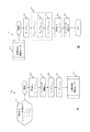
図1A及び図1Bは、例示的なワイヤレス電力伝送システム100の図を示す。図1Aを参照して、システム100は、ワイヤレス電力送信機102及びワイヤレス電力受信機104を含む。ワイヤレスで電力を供給され、或いはワイヤレスで充電される装置112が、受信機104に結合される。ワイヤレスで電力を供給され、或いはワイヤレスで充電される装置112には、例えば、電気自動車などの高電力装置、或いはラップトップパソコン、スマートフォン、タブレット、並びにデスクトップ、テーブルトップ、バートップ、及びその他の種類の表面上に一般に設置される他のモバイル電子装置などの電子機器が、含まれ得る。
1A and 1B show diagrams of an exemplary wireless
説明のために、ワイヤレス電力伝送システム100は、電気自動車のためのワイヤレス充電システムに関するものとして説明する。例えば、システム100は、広範囲の結合係数k、負荷条件(電池電圧など)、及び共振器のインダクタンスを狂わせる環境条件(例えば、空間的な変化、干渉物)において動作することが求められるHRWPTシステムであってもよい。更に、電気自動車のワイヤレス充電を実行するために、システム100は、高電圧(例えば360Vから800Vの間)及び高電流(例えば26Aから40Aの間)にて動作して、適切な電力の範囲(例えば、0から3.7kW、0から7.7kW、0から11kW、或いは0から22kW)を達成することが求められ得る。
For purposes of illustration, the wireless
ワイヤレス電力送信機102は、外部電源(例えば、電力網又は発電機)からの電力を、共振器108T及び108Rの間でワイヤレス電力受信機104に送信される、電磁エネルギーに変換する。受信機104は、共振器108Rにて受信した振動エネルギーを、装置112による使用(例えば、電気自動車のバッテリの充電)のために適切な形態に変換する。より具体的には、受信機の電力制御回路110は、装置112に対して適切な電圧及び電流のパラメータを用いて、共振器108RからのAC電圧及び電流を、DC電力に変換し得る。
The
送信機の電力制御回路106は、ソース電子機器を電源から絶縁するための回路及び構成要素を含むことができるので、反射された電力又は信号はソース入力端子を介して外部と結合されない。ソース電力制御回路106は、10kHzより大きく100MHzより小さい(例えば、85kHz)の周波数などで、交流電流でソース共振器108Sを駆動させ得る。ソース電力制御回路106は、例えば、力率補正(PFC)回路、送信機コントローラ、インピーダンスマッチング回路、電力インバータ、DC/DCコンバータ、AC/DCコンバータ、電力増幅器、又はそれらの任意の組み合わせを含み得る。
The
受信機の電力制御回路110は、受信機の共振器108Rからの交流電力を、1つ以上の装置112に給電又は充電するのに適した、安定した直流電力に変換するように設計され得る。例えば、受信機の電力制御回路110は、共振器108Rからの1つの周波数(例えば、85kHz)の交流電力を、1つ以上の装置112に給電又は充電するのに適した、異なる周波数の交流電力に変換するように設計され得る。受信機の電力制御回路110は、例えば、受信機コントローラ、インピーダンスマッチング回路、整流回路、電圧制限回路、電流制限回路、AC/DCコンバータ回路、DC/DCコンバータ回路、DC/AC回路、AC/AC変換回路、及びバッテリ充電制御回路を含み得る。
The
送信機102及び受信機104は、例えば動的インピーダンスマッチング回路などの、ソース及び装置共振器の処理、並びに電力移動の効率に影響を及ぼす可能性のある、可変の環境条件、摂動及び負荷条件を補償するために処理点の調整を可能にする、チューニング能力を有し得る。チューニング能力は自動的に制御されることができ、連続的に、定期的に、断続的に、又はスケジューリングされた時間若しくは間隔で、実行されることができる。ある実施形態では、チューニングは、以下でより詳細に説明するように、送信機102と受信機104との間で同期して実行される。
The
図1Bに、送信機102及び受信機104の電力制御回路106及び110をより詳細に示す。図1A及び図1Bに示すように、送信機102は、送信機インピーダンスマッチングネットワーク(IMN)124に電力を供給するインバータ122と、インバータ122の処理を制御し、送信機IMN124をチューニングするコントローラ125とを備える。送信機IMN124は、共振器コイル108Tと結合される。受信機104は、共振器108Rに結合される受信機IMN126、整流器128、及び受信機IMN126をチューニングすることができるコントローラ129を備える。処理中、インバータ122は送信機IMN124を介して共振器108Tに電力を供給する。共振器108Tは、結合定数kを用いて振動電磁エネルギーを共振器108Rに結合する。共振器108Rによって受信された電力は、受信機IMN126を介して整流器108に送信され、整流器108は、電力を装置112による使用のための適切な形式に変換する。
FIG. 1B shows the
送信機コントローラ125及び受信機コントローラ129は、プロセッサ又はマイクロコントローラとして実装され得る。ある実施形態では、送信機コントローラ125及び受信機コントローラ129は、ASIC又はFPGAコントローラとして実装されてもよい。送信機コントローラ125及び受信機コントローラ129は、同じ形式で実装される必要はない。例えば、送信機コントローラ125は、マイクロコントローラとして実装され、受信機コントローラ129は、ASICコントローラとして実装されてもよい。
The
送信機102はまた、送信機処理パラメータを測定するための電圧、電流、及び電力センサなどの複数のセンサを含む。送信機コントローラ125は、センサからの測定値を使用して、送信機102の処理を制御し、送信機IMN124をチューニングし得る。センサによって測定される送信機処理パラメータには、インバータのバス電圧(Vbus)、送信機入力電力、インバータのAC電圧(VAC)、インバータのAC電流(IAC)、送信機力率(pf)、並びに安全チェック(safety check)に用いられる他の電圧及び電流、が含まれ得るが、これらに限定されない。ある実施形態では、送信機入力電力は、送信機PFC回路へのAC入力で測定される。また、ある実施形態では、図1Bに示すように、送信機入力電力は、インバータ電力(Pin)として測定される。ある実施形態では、インバータ電力(Pin)は、インバータ122のDC入力で測定される。また、ある実施形態では、インバータ電力(Pin)は、インバータ122のAC出力で測定される。送信機電力係数は、インバータのAC電圧(VAC)とインバータのAC電流(IAC)との間の位相差(φ)として測定され、力率は位相差(φ)のコサインとなる。ある実施形態では、位相差(φ)は、力率の代理として使用され得る。すなわち、送信機コントローラ125は、実際の力率値を計算する代わりに、位相差(φ)に基づいて処理を実行し得る。ある実施形態では、送信機力率(pf)は、インバータの出力に見られる等価抵抗値及びリアクタンス値に基づいて計算できます。例えば、位相差(φ)は、
式(4)
で表される。
The
Equation (4)
It is represented by.
受信機104はまた、受信機処理パラメータを測定するための電圧、電流、及び電力センサなどの複数のセンサを含む。受信機コントローラ129は、センサからの測定値を使用して、受信機104の処理を制御し、受信機IMN126をチューニングし得る。センサによって測定される受信機処理パラメータには、受信機出力電力(Pout)、整流器のAC電圧、整流器のAC電流、整流器のDC電圧、整流器のDC電流、並びに安全チェックに用いられる他の電圧及び電流、が含まれ得るが、これらに限定されない。
The
送信機IMN124及び受信機IMN126は、それぞれ、抵抗器、キャパシタ、インダクタ、又はそれらの組み合わせなどの、複数の固定及び可変のインピーダンスマッチングの構成要素を含み得る。可変インピーダンス構成要素は、可変でリアクティブなインピーダンス構成要素であって、PWMスイッチングキャパシタ、無線周波数(RF)における実効キャパシタンスがDCバイアス電場によって制御される無線周波数(RF)制御キャパシタ、温度制御キャパシタ、PWMスイッチングインダクタ、実効インダクタンスがバイアスDC電界(例えば、可飽和コア)によって制御されるDC制御インダクタ,温度制御インダクタ、スイッチによって回路の内外にスイッチングされるリアクタンス素子のアレイ、又はそれらの組み合わせを含み得るが、これらに限定されない、チューニング可能なリアクタンスインピーダンス構成要素であってもよい。 The transmitter IMN124 and the receiver IMN126, respectively, may include multiple fixed and variable impedance matching components such as resistors, capacitors, inductors, or combinations thereof. The variable impedance component is a variable and reactive impedance component, which is a PWM switching capacitor, a radio frequency (RF) control capacitor in which the effective capacitance at the radio frequency (RF) is controlled by a DC bias electric field, a temperature control capacitor, and the like. It may include a PWM switching inductor, a DC control inductor whose effective inductance is controlled by a bias DC electric field (eg, saturable core), a temperature control inductor, an array of reactance elements whose effective inductance is switched inside and outside the circuit by a switch, or a combination thereof. However, it may be a tunable reactance impedance component without being limited to these.
図示の例では、送信機IMN124は、直列キャパシタ132、並列キャパシタ134、及びキャパシタ136とインダクタ138との組み合わせを、インバータ122の出力部分に備える。キャパシタ136は可変キャパシタであって、1つ以上の可変キャパシタを含み得る。トランジスタ共振器コイル108Tの抵抗成分は、抵抗140によって表される。
In the illustrated example, the transmitter IMN124 includes a
受信機IMN126は、直列キャパシタ144、並列キャパシタ146、及びキャパシタ148とインダクタ150との組み合わせを、整流器128の入力部分に備える。キャパシタ148は可変キャパシタであって、1つ以上の可変キャパシタを含み得る。受信機共振器コイル108Rの抵抗成分は、抵抗152によって表される。
The receiver IMN126 includes a series capacitor 144, a
IMN124及びIMN126は、特定のアプリケーションのニーズを満たすインピーダンスを有する様々な構成要素を用いた、広い範囲の回路実装を有し得る。例えば、Kesler氏等による米国特許第8,461,719号は、その全体が参照により本明細書に組み込まれ、図28a〜図37b等に、様々なチューニング可能なインピーダンスネットワーク構成が開示される。ある実施形態では、図1Bに示される各構成要素は、ネットワーク又は構成要素のグループを表し得る。 IMN124 and IMN126 may have a wide range of circuit implementations with various components having impedances that meet the needs of a particular application. For example, U.S. Pat. No. 8,461,719 by Kessler et al. Is incorporated herein by reference in its entirety, and various tunable impedance network configurations are disclosed in FIGS. 28a-37b and the like. In certain embodiments, each component shown in FIG. 1B may represent a network or group of components.
IMN124及びIMN126の各々は、直列リアクタンスX1(例えば、キャパシタ132又は144)、並列リアクタンスX2(例えば、キャパシタ134又は146)、及びインバータ出力/整流器入力リアクタンスX3(インダクタ138又は150とキャパシタ136又は148との間の合成リアクタンス)の3つのリアクタンスを含む。受信機IMN126のリアクタンスX1〜X3は、送信機IMN124の対応するリアクタンスX1〜X3を反映する。リアクタンスX3は、チューニング可能なリアクタンスの構成要素、すなわちキャパシタ136及び148を含むものとして示されている唯一のリアクタンスであるが、他の実施形態では、リアクタンスX1及びX2も、リアクタンスX3のチューニング可能なリアクタンス構成要素に加えて、又はその代わりにチューニング可能なリアクタンス構成要素を含み得る。言い換えれば、IMN124及びIMN126は、リアクタンスX1〜X3のいずれか1つ以上をチューニングすることによって、チューニングされ得る。ある実施形態では、リアクタンスX1及びX3を構成する構成要素のバランスを取り得る。
Each of IMN124 and IMN126 has a series reactance X1 (eg,
リアクタンスX1、X2、X3、又はそれらの組み合わせの何れもがチューニング可能であるが、ある実施形態では、リアクタンスX3をチューニングすることが有利となり得る。例えば、リアクタンスX3をチューニングすることによって、IMN内の単一の構成要素をチューニングするだけで十分であれば、システムの複雑さ及びコストを低減することができる。リアクタンスX3をチューニングすることにより、X3素子を流れる電流を、X1、X2、及び共振器コイルによって形成されるタンク回路を流れる電流よりも大幅に少なくすることができる。このように電流が少なくなることによって、例えば、それらの構成要素に必要とされる電流定格を低減させて、チューニング可能な構成要素の実装をより費用対効果の高いものにすることができる。更に、電流が少なくなることによって、X3における素子のチューニングによる、損失を低減することができる。 Although any of the reactances X1, X2, X3, or a combination thereof can be tuned, in some embodiments it may be advantageous to tune the reactance X3. For example, by tuning the reactance X3, the complexity and cost of the system can be reduced if it is sufficient to tune a single component within the IMN. By tuning the reactance X3, the current flowing through the X3 element can be made significantly smaller than the current flowing through the tank circuit formed by the X1, X2, and the resonator coils. Such low currents can, for example, reduce the current ratings required for those components, making the implementation of tunable components more cost effective. Further, by reducing the current, the loss due to the tuning of the element in X3 can be reduced.
ある実施形態では、チューニング可能なリアクタンス素子(例えば、PWM制御キャパシタ)は、調波ノイズ(harmonic noise)をHRWPTシステムに注入することができる。EMIコンプライアンスを助けるために、この調波ノイズを主なHRWPT共振器コイル(例えば、108T及び108R)から遠ざけることが望ましい場合がある。X3でチューニング可能な素子によって注入された高調波は、インバータ及び整流器によって生成されるものよりも抑制され、共振器コイル108T又は108Rに達する前に、残りのHRWPT回路によって著しく抑制され得る。
In certain embodiments, a tunable reactance element (eg, a PWM control capacitor) can inject harmonic noise into the HRWPT system. It may be desirable to keep this harmonic noise away from the main HRWPT resonator coils (eg 108T and 108R) to aid in EMI compliance. The harmonics injected by the X3 tuneable element are more suppressed than those produced by the inverter and rectifier and can be significantly suppressed by the remaining HRWPT circuit before reaching the
X3にチューニング可能な素子(例えば、PWM制御キャパシタ)を有する、ある実施形態では、チューニング可能な素子は、システムの残りの部分の全体的な効率が最も低い場合には、最小量の電力(理論的にはゼロ)を散逸させ、残りの部分の全体的な効率が最も高い場合には、最大量の電力を散逸させる。これは、最大効率にわずかにしか影響を与えずに、システムの最小及び平均効率を最適化する望ましい効果を有する。しかし、X1又はX2の素子をチューニングすることは、反対の、あまり望ましくない効果を生じ得る。 In certain embodiments, the X3 has a tunable element (eg, a PWM control capacitor), the tunable element has the least amount of power (theoretical) when the overall efficiency of the rest of the system is the lowest. It dissipates zero) and dissipates the maximum amount of power when the overall efficiency of the rest is highest. This has the desired effect of optimizing the minimum and average efficiency of the system with little impact on maximum efficiency. However, tuning the elements of X1 or X2 can produce the opposite, less desirable effect.
X1及びX2の固定リアクタンスとX3のベースリアクタンス値は、図2A〜図2Dに示す結果を達成するために選択されることができ、これを以下に説明する。例えば、X1とX2の値は、次のようにして判定され得る。1)X3を含む回路分岐を流れる最大電流と、チューニング可能なリアクタンス素子の実装にて使用される構成要素の電流定格及び電圧定格とに基づいて達成できるリアクティブ・チューニングの最大範囲を判定する。例えば、単一段階のリアクタンス素子が20Ωのリアクティブ・チューニングに影響を与え得ると結論づけてもよい。2)受信機側IMNに対して、X1、X2、及びX3のベース値を最適化して、共振器の相対的な位置(及び負荷条件)の範囲にわたってコイル−コイル間の効率を最適化し、及び/又は、共振器内で消費される電力の量がステップ1で判定されたリアクタンスの範囲に基づいて指定された制限値より下に留まるようにする。3)送信機側IMNに対して、X1、X2、及びX3のベース値を最適化して、インバータに望ましい実効インピーダンスを与える(例えば、クラスDインバータのゼロ電圧スイッチングを実現するには十分に誘導性であるが、過大な無効電流が存在する場合でも過度に導電性ではなく、実際に達成され得るバス電圧の範囲内に入る大きさを有する)。
The fixed reactance values of X1 and X2 and the base reactance values of X3 can be selected to achieve the results shown in FIGS. 2A-2D, which will be described below. For example, the values of X1 and X2 can be determined as follows. 1) Determine the maximum range of reactive tuning that can be achieved based on the maximum current flowing through the circuit branch including X3 and the current and voltage ratings of the components used in the mounting of the tunable reactance element. For example, one may conclude that a single-stage reactance device can affect 20Ω reactive tuning. 2) For the receiver side IMN, optimize the base values of X1, X2, and X3 to optimize the coil-to-coil efficiency over the range of relative positions (and load conditions) of the resonator, and / Or ensure that the amount of power consumed in the resonator remains below the limit specified based on the reactance range determined in
図2A〜図2Dは、受信機X3のチューニングの影響に関するプロットを示す。図2Aは、(負荷に対してW/kWで示される)ソース(送信機)共振器電力損失を、品質係数比
![]()
式(5)
であって、ここで、
式(6)
は、無装荷(unloaded)の装置(受信機)の共振器の品質係数であり、
![]()
式(7)
は、装荷(loaded)の装置の共振器(装荷は、残りの装置回路及び負荷の装荷を含む)の品質係数である品質係数比と、性能指数
式(8)
との関数で示す。図2Aは、性能指数が送信機共振器での損失において、支配的な役割を果たすことを示している。
2A-2D show plots regarding the effects of tuning receiver X3. FIG. 2A shows the source (transmitter) resonator power loss (indicated by W / kW with respect to the load) as a quality factor ratio.
![]()
Equation (5)
And here,
Equation (6)
Is the quality factor of the resonator of the unloaded device (receiver),
![]()
Equation (7)
Is the quality coefficient ratio, which is the quality coefficient of the resonator of the loaded device (the loading includes the remaining device circuit and the loading of the load), and the figure of merit.
Equation (8)
It is shown by the function of. FIG. 2A shows that the figure of merit plays a dominant role in the loss at the transmitter resonator.
図2Bは、(負荷に対してW/kWで示される)装置共振器電力損失を、品質係数比
式(9)
であって、ここで、
式(10)
は、無装荷の装置の共振器の品質係数であり、
![]()
式(11)
は、装荷の装置の共振器(装荷は、残りの装置回路及び負荷の装荷を含む)の品質係数である品質係数比と、性能指数
![]()
式(12)
との関数で示す。図2Bは、品質係数比が受信機共振器での損失において、支配的な役割を果たすことを示している。
FIG. 2B shows the device resonator power loss (indicated by W / kW with respect to the load) as a quality factor ratio.
Equation (9)
And here,
Equation (10)
Is the quality factor of the resonator of the unloaded device,
![]()
Equation (11)
Is the quality coefficient ratio, which is the quality coefficient of the resonator of the loaded device (the loading includes the remaining device circuit and the loading of the load), and the figure of merit.
![]()
Equation (12)
It is shown by the function of. FIG. 2B shows that the quality coefficient ratio plays a dominant role in the loss at the receiver resonator.
図2Cは、動作周波数84kHzにおける装置性能指数Udを、位置X3でのリアクタンスdX(単位はオーム)及び負荷抵抗RL(単位はオーム)の変化の関数として示す。性能指数Udは、
式(13)
で定義される。ここで、RL,eqは、装置の共振器の(整流器、及びバッテリなどの、装置の電子回路による)装荷の等価直列抵抗(ESR)であって、Rdは、装置の共振器の無装荷のESRである。Udがシステムの性能指数Uと等しく設定されると、コイル対コイルの効率が最大となり得る。
Figure 2C shows an apparatus performance index U d at the operating frequency 84KHz, as a function of the change in the dX reactance at position X3 (units Ohm) and the load resistor R L (units Ohm). The figure of merit Ud is
Equation (13)
Defined in. Here, RL and eq are the equivalent series resistance (ESR) of the load of the resonator of the device (by the electronic circuit of the device such as the rectifier and the battery), and R d is the absence of the resonator of the device. ESR of loading. When U d is set equal to the figure of merit U of the system, coil-to-coil efficiency can be maximized.
図2Dは、84kHzの動作周波数における位相ψ(単位は度)を、リアクタンス(単位はオーム)及び負荷抵抗(単位はオーム)の変化の関数として示す。位相ψは、
式(14)
で定義される。ここで、
式(15)
は、動作周波数で装荷の装置共振器の残留リアクタンスである。位相ψ=0は、装荷の装置共振器が共振状態にあることを意味する。
FIG. 2D shows the phase ψ (unit: ohm) at an operating frequency of 84 kHz as a function of changes in reactance (unit: ohm) and load resistance (unit: ohm). Phase ψ is
Equation (14)
Defined in. here,
Equation (15)
Is the residual reactance of the loaded device resonator at the operating frequency. The phase ψ = 0 means that the loaded device resonator is in resonance.
図2C及び図2Dの台形の点線の輪郭202は、ワイヤレス電力伝送受信機の動作範囲を示す。図2Dの輪郭202は、11kWの出力で動作するワイヤレス電力伝送システムで見られるRLの範囲を示す。例えば、RL=10Ωの場合、図2Cに示すように、RL=10ΩでのdXの範囲で、X3をチューニングする重要な能力があり、ψ=0の曲線のRL=10Ωへの近似によって図2Dに示されるように、ほぼ共振を維持している(又は共振器の離調を回避している)。
The trapezoidal dotted
再び図1Bを参照すると、コントローラ125及び129は、IMN124及び126を同期的にチューニングして、それぞれ、システム100が輪郭202のような好ましい動作範囲で動作するように維持する。例示的な実施形態では、コントローラ125及び129は、電気自動車などの装置112に安全かつ効率的に電力を転送するために、以下に説明するプロセスを実行して、送信機及び受信機のIMN124及び126のリアクタンスX3を同期的にチューニングする。例えば、コントローラ125及び129は、帯域外通信チャネルで電子通信を行うためにワイヤレス通信インタフェースを含み得る。コントローラ125と129との間の通信には、RF通信(例えば、WiFi、Bluetooth、Zigbee)、光通信、赤外線通信、超音波通信、又はそれらの組み合わせが含まれ得るが、これらに限定されない。
Referring again to FIG. 1B,
例えば、図3〜図5Cを参照して以下でより詳細に説明するように、コントローラ125は、送信機IMN124をチューニングして、送信機102の目標電力特性を達成することができ、コントローラ129は、受信機IMN126をチューニングして、目標システム効率を達成することができる。送信機コントローラ125は、IMN124を調整して、送信機102の目標電力特性を達成して維持する。送信機コントローラ125は、入力電力データを受信機コントローラ129に送信する。受信機コントローラ129は、受信機104の出力電力を測定して、入力電力データと共に、システム100の効率を算出する。受信機コントローラ129は、受信機IMN126をチューニングして、システム効率を最大にする。例えば、受信機コントローラ129は、2つの異なる時間において計算された効率値の比較に基づいて、受信機IMN126に対する適切な調整を判定する。
For example, the
ある実施形態では、送信機コントローラ125は、受信機コントローラ129よりも早い速度で動作する。つまり、送信機コントローラ125は、受信機コントローラ129が受信機IMN126をチューニングするよりも速い速度で送信機IMN124をチューニングすることができる。例えば、受信機コントローラ129は、送信機コントローラ125からの新しい入力電力データを受信するのと同じ速度で受信機IMN126をチューニングすることのみを許可されてもよい。
In certain embodiments, the
図3は、ワイヤレス電力伝送システムを動作させるための例示的な制御プロセス300のフローチャートを示す。ある例では、例示的なプロセス300は、1つ以上の処理装置(例えば、プロセッサ又はマイクロコントローラ)又は計算装置を使用して実行されるコンピュータ実行可能命令として提供され得る。ある例では、プロセス300は、ハードウェアとして組み込まれた電気回路によって、例えばASIC又はFPGAコントローラとして実行されてもよい。
FIG. 3 shows a flowchart of an
プロセス300の一部は、ワイヤレス電力送信機102(例えば、送信機コントローラ125)によって実行され、プロセス300の一部は、ワイヤレス電力受信機104(例えば、受信機コントローラ129)によって実行される。プロセス300は、2つの制御ループ303及び305を含む。ループ303は、送信機102によって実行され、リアクタンスX3を調整することによって送信機IMN124をチューニングして、送信機電力を制御する。ある実施形態では、ループ303は、実行されるべき他の装置(例えば、受信機104)との通信を必要としないローカルループである。また、ある実施形態では、ループ303は、送信機によって1〜10kHzで実行される。ループ303は、
式(16)
で特徴付けることができる。ここで、Piは、インバータの電力、Vbusは、インバータ122のDCバス電圧、Rinvは、インバータから見た実効抵抗、Xinvは、インバータから見た実効リアクタンスである。
Part of the
Equation (16)
Can be characterized by. Here, P i, of the inverter power, V bus is DC bus voltage, R inv of the
ループ305は、システム効率に基づいて受信機IMN126をチューニングするために受信機104によって実行される。例えば、ループ305は、「摂動観測(perturb-and-observe)」ストラテジを使用して、受信機IMN126のリアクタンスX3を調整することによって効率を向上し、連続するイテレーションにわたって効率を継続的に向上することができる。ループ305は、各イテレーションにおいて、送信機102からの入力電力データに依存して、システム効率を計算する。ある実施形態では、ループ305は、例えば40Hzの、送信機102と受信機104との間の通信速度で処理する。
ブロック302は、最大リアクタンス値Xtx,maxを設定された、可変送信機リアクタンスXtx(例えば、送信機IMN124のX3)と、最小リアクタンス値Xrx,minを設定された、可変受信機リアクタンスXrx(例えば、受信機IMN126のX3)と、最初にゼロを設定されたシステム効率ηと、δの調整値を設定された、送信機リアクタンスステップサイズΔXtxと、εの調整値を設定された、受信機リアクタンスステップサイズΔXrxと、を含むプロセス300の入力及び初期条件を列挙している。ある実施形態では、リアクタンスステップサイズΔXtx及びΔXrxは定数値である。また、ある実施形態では、リアクタンスステップサイズΔXtx及びΔXrxは変数である。例えば、コントローラ125又はコントローラ129は、プロセス300の間に、それぞれのステップサイズの大きさを動的に増加又は減少させ得る。
The
プロセス300は、ステップ304で開始する。ステップ306では、送信機102の電力が測定される。送信機コントローラ125は、入力電力Pinを測定し、ステップ306において、入力電力Pinを目標電力レベルPtargetと比較する。PinがPtargetに等しい場合、プロセス300はループ305のステップ308に進む。PinがPtargetに等しくない場合、プロセス300はループ303のステップ316に進む。ある実施形態又はある処理モードでは、目標電力レベルは、送信機102によって設定される。ある実施形態又はある処理モードでは、目標電力レベルは、受信機104によって設定される。例えば、定常状態の処理(例えば、起動シーケンス又はシャットダウンシーケンス以外の通常の処理)において、システム100は、要求ベースシステムとして処理することができる。例えば、受信機104は、送信機102からの電力レベルを要求することができる。送信機コントローラ125は、受信機104からの要求電力レベルに基づいて、目標入力電力レベルを計算することができる。例えば、送信機コントローラ125は、要求電力を、(IMN損失及びインバータ損失等の)送信機における予想損失を考慮した、要求電力レベルを送信するために必要とされる、目標入力電力レベルに変換することができる。
Process 300 starts in
最初に送信機側ループである、ループ303を参照すると、送信機の入力電力(例えば、インバータ電力)が目標電力と等しくない場合、ステップ316において、送信機コントローラ125は、入力電力を目標電力レベルと比較して、入力電力が目標電力レベルよりも小さいか否かを判定する。PinがPtargetよりも小さい場合、ステップ318において、送信機コントローラ125は、送信機リアクタンスステップサイズΔXtxを、負の調整値に設定して、ステップ320において、可変送信機リアクタンスXtxを減少させる。PinがPtargetより小さくない場合、ステップ322において、送信機コントローラ125は、送信機リアクタンスステップサイズΔXtxを正の調整値に設定して、ステップ320において、可変送信機リアクタンスXtxを増加させる。ある実施形態では、リアクタンス調整値δの大きさは可変である。例えば、PinとPtargetとの差が大きい場合、例えば、粗調整閾値よりも大きい場合、送信機コントローラ125は、リアクタンス調整値δの大きさを増加させ得る。これに対応して、PinとPtargetとの間の差が小さい場合、例えば微調整閾値よりも小さい場合、送信機コントローラ125は、リアクタンス調整値δの大きさを減少させ得る。可変送信機リアクタンスXtxがステップ320で調整された後、ループ303はステップ306に戻り、そこで入力電力は目標電力レベルと再び比較される。
With reference to
受信機側ループである、ループ305を参照すると、ステップ308において、送信機の入力電力が目標電力と等しい場合、受信機コントローラ129は、システム100の効率を測定する。例えば、PinがPtargetと等しい場合、送信機は、Pinの測定値を示すデータを受信機104に送信することができる。(測定された送信機電力は、浮動小数点数で表すことができるため、目標電力と厳密には等しくないこともあるが、予め設定された許容誤差の範囲内で同等であってもよい。)受信機コントローラ129は、受信機の出力電力を測定し、受信した送信機電力データ及び測定された受信機出力電力値に基づいて、時間nにおけるシステム効率η(n)を計算する。
Referring to
ステップ310において、受信機コントローラ129は、時間nにおいて計算されたシステム効率を、前の時間n−1において計算されたシステム効率と比較する。時間nにおける効率が時間n−1における効率よりも大きい場合、ステップ312において、可変受信機リアクタンスXrxは、受信機リアクタンスステップサイズΔXrxによって調整される。例えば、受信機リアクタンスの変化ΔXrxが可変受信機リアクタンスXrxに加えられる。時間nにおける効率が時間n−1における効率よりも大きくない場合、ステップ314において、受信機コントローラ129は、ステップ312において可変受信機リアクタンスXrxを調整する前に、受信機リアクタンスステップサイズΔXrxの符号を変更する。例えば、受信機リアクタンスの変化値εは無効にされ得る。例えば、可変受信機リアクタンスXrxの調整の方向は、効率がもはやループ305の後続のイテレーションと間で増加しなくなったときに交換される。ループ305によって示されるように、可変受信機リアクタンスXrxの調整の方向は、効率が再び低下し、それにより、略最大システム効率が維持されるまで、ループ305の後続のイテレーションで維持される。
In
ある実施形態では、リアクタンス調整値εの大きさを変えることができる。例えば、時間nにおける効率が粗調整閾値より小さい場合(例えば、システム起動直後)、受信機コントローラ129は、リアクタンス調整値εの大きさを増加させることができる。これに対応して、時間nにおける効率が、例えば推定された最大値の微調整閾値内である等、推定された最大値に近い場合、受信機コントローラ129は、リアクタンス調整値εの大きさを減少させることができる。
In certain embodiments, the magnitude of the reactance adjustment value ε can be changed. For example, when the efficiency at time n is smaller than the coarse adjustment threshold value (for example, immediately after the system is started), the
図4は、ワイヤレス電力伝送システムを動作させるための例示的な制御プロセス400のフローチャートを示す。ある例では、例示的なプロセス400は、1つ以上の処理装置(例えば、プロセッサ又はマイクロコントローラ)又は計算装置を使用して実行されるコンピュータ実行可能命令として提供され得る。ある例では、プロセス400は、ハードウェアとして組み込まれた電気回路によって、例えばASIC又はFPGAコントローラとして実行されてもよい。
FIG. 4 shows a flowchart of an
プロセス400は、プロセス300と同様であるが、送信機電力Pinを調整するためのインバータのバス電圧Vbusの制御と、インバータ力率(例えば、インバータAC電圧VAC及びインバータAC電流IAC、位相差φ)の測定及び使用とを含み、送信機IMN124をチューニングする。
The
プロセス400の一部は、ワイヤレス電力送信機102(例えば、送信機コントローラ125)によって実行され、プロセス400の一部は、ワイヤレス電力受信機104(例えば、受信機コントローラ129)によって実行される。プロセス400は、3つの制御ループ401、403及び405を含む。ループ401及び403は、送信機102によって実行され、送信機IMN124をチューニングし、送信機電力を制御する。ループ401は、インバータAC出力電圧とインバータAC出力電流との間の目標位相φ関係(例えば、インバータ力率)を達成するために、リアクタンスX3を調整することによって、送信機IMN124を調整する位相ループである。以下、「インバータ出力位相φinv」及び「目標インバータ出力位相φtarget」ともいう。ループ403は、インバータのバス電圧Vbusを調整することによって、目標電力Ptarget又はその近傍における送信機電力の大きさPinを制御及び維持する電力制御ループである。ある実施形態では、ループ401及び403は、実行されるべき他の装置(例えば、受信機104)との通信を必要としないローカルループである。また、ある実施形態では、ループ401及び403は、送信機によって1〜10kHzで実行される。ループ401及び403は、
で特徴付けることができる。ここで、Pinは、インバータの電力、Vbusは、インバータ122のDCバス電圧、Rinvは、インバータから見た実効抵抗、Xinvは、インバータから見た実効リアクタンスである。
Part of the
Can be characterized by. Here, P in the inverter power, V bus is DC bus voltage, R inv of the
ループ405は、システム効率に基づいて受信機IMN126をチューニングするために、受信機104によって実行される。ループ405は、プロセス300のループ305と同様である。例えば、ループ405は、「摂動観測」ストラテジを使用して、受信機IMN126のリアクタンスX3を調整することによって効率を向上し、連続するイテレーションにわたって効率を継続的に向上することができる。ループ405は、各イテレーションにおいて、送信機102からの入力電力データに依存して、システム効率を計算する。ある実施形態では、ループ405は、例えば40Hzの、送信機102と受信機104との間の通信速度で処理する。
ブロック402は、最大リアクタンス値Xtx,maxを設定される可変送信機リアクタンスXtx(例えば、送信機IMN124のX3)と、最小リアクタンス値Xrx,minを設定される可変受信機リアクタンスXrx(例えば、受信機IMN126のX3)と、最初にゼロに設定されるシステム効率ηと、0より大きい調整値を設定される送信機リアクタンスステップサイズΔXtxと、0より大きい調整値を設定される受信機リアクタンスステップサイズΔXrxと、0より大きい調整値を設定されるバス電圧ステップサイズΔVbusと、を含む、プロセス400の入力及び初期条件を列挙する。ある実施形態では、リアクタンスステップサイズΔXtx及びΔXrxとバス電圧ステップサイズΔVbusとは定数値である。ある実施形態では、リアクタンスステップサイズΔXtx及びΔXrxとバス電圧ステップサイズΔVbusは変数である。例えば、コントローラ125又はコントローラ129は、プロセス400の間に、それぞれのステップサイズの大きさを動的に増加又は減少させ得る。
The
プロセス400は、ステップ404にて開始する。ステップ406において、送信機コントローラ125は、インバータ出力位相φinvを測定し、測定されたインバータ出力位相φinvを目標インバータ出力位相φtargetと比較する。φinvがφtargetに等しい場合、プロセス400はループ403のステップ408に進む。φinvがφtargetに等しくない場合、プロセス400はループ401のステップ424に進む。ある実施形態では、φtargetは0よりわずかに大きいので、インバータはわずかな誘導負荷のままであるとみられる。
最初に位相ループである、ループ401を参照すると、インバータ出力位相が目標インバータ出力位相と等しくない場合、ステップ406において、送信機コントローラ125は、インバータ出力位相を目標インバータ出力位相と比較して、ステップ424において、インバータ出力位相が目標インバータ出力位相よりも大きいか否かを判定する。φinvがφtargetより大きい場合、ステップ426において、送信機コントローラ125は、可変送信機リアクタンスXtxが既に最小値Xtx,minであるか否かをチェックする。可変送信機リアクタンスXtxが既に最小値Xtx,minである場合、ループ401は、可変送信機リアクタンスXtxに対する調整を行わずに、ステップ408に進む。可変送信機リアクタンスXtxが最小値Xtx,minでない場合、ステップ438において、送信機コントローラ125は、可変送信機リアクタンスXtxを、送信機リアクタンスステップサイズΔXtxだけデクリメントし、ループ401は、ステップ406に戻り、インバータ出力位相を再評価する。
With reference to
ステップ424において、φinvがφtargetよりも大きくない場合、ステップ430において、送信機コントローラ125は、可変送信機リアクタンスXtxが既に最大値Xtx,maxであるか否かをチェックする。可変送信機リアクタンスXtxが既に最大値Xtx,maxである場合、ループ401は、可変送信機リアクタンスXtxに対する調整を行わずに、ステップ408に進む。可変送信機リアクタンスXtxが最大値Xtx,maxでない場合、ステップ432において、送信機コントローラ125は、送信機リアクタンスステップサイズΔXtxだけ可変送信機リアクタンスXtxをインクリメントし、ループ401は、ステップ406に戻り、インバータ出力位相を再評価する。
In
電力ループである、ループ403を参照すると、ステップ408において、送信機コントローラ125は、入力電力Pinを測定し、測定された入力電力Pinを目標電力レベルPtargetと比較する。PinがPtargetに等しい場合、プロセス400はループ401のステップ406に戻る。更に、送信機コントローラ125は、Pinの測定値を示すデータを受信機104に送信することができる。PinがPtargetと等しくない場合、プロセス400はステップ418に進む。ある実施形態又はある処理モードでは、目標電力レベルは、送信機102によって設定される。また、ある実施形態又はある処理モードでは、目標電力レベルは、受信機104によって設定される。例えば、定常状態の処理(例えば、起動シーケンス又はシャットダウンシーケンス以外の通常の処理)、システム100は、要求ベースシステムとして処理することができる。例えば、受信機104は、送信機102からの電力レベルを要求することができる。送信機コントローラ125は、受信機104からの要求電力レベルに基づいて、目標入力電力レベルを計算することができる。例えば、送信機コントローラ125は、要求電力を、(IMN損失及びインバータ損失等の)送信機における予想損失を考慮した、要求電力レベルを送信するために必要とされる、目標入力電力レベルに変換することができる。
A power loop, referring to
送信機の電力が目標電力と等しくない場合、ステップ418において、送信機コントローラ125は入力電力を目標電力レベルと比較して、入力電力が目標電力レベルより小さいか否かを判定する。PinがPtargetよりも小さい場合、ステップ420において、送信機コントローラ125は、インバータ電圧Vbusをバス電圧ステップサイズΔVbusだけインクリメントし、ループ403はステップ408に戻り、送信機の電力を再評価する。PinがPtargetよりも小さくない場合、ステップ422において、送信機コントローラ125は、インバータバス電圧Vbusをバス電圧ステップサイズΔVbusだけデクリメントし、ループ403はステップ408に戻り、送信機の電力を再評価する。
If the power of the transmitter is not equal to the target power, in
ある実施形態では、送信機リアクタンスステップサイズΔXtxの大きさは変更可能である。例えば、φinvとφtargetの差が大きい場合、例えば、粗調整閾値よりも大きい場合、送信機コントローラ125は、送信機リアクタンスステップサイズΔXtxを増加させ得る。これに対して、φinvとφtargetの差が小さい場合、例えば、微調整閾値よりも小さい場合、送信機コントローラ125は送信機リアクタンスステップサイズΔXtxの大きさを減少させ得る。
In certain embodiments, the magnitude of the transmitter reactance step size ΔX tx is mutable. For example, when the difference between φ inv and φ target is large, for example, when it is larger than the coarse adjustment threshold value, the
ある実施形態では、バス電圧ステップサイズΔVbusの大きさは変更可能である。例えば、PinとPtargetの差が大きい場合、例えば粗調整閾値よりも大きい場合、送信機コントローラ125はバス電圧ステップサイズΔVbusを増加させ得る。これに対応して、PinとPtargetとの間の差が小さい場合、例えば微調整閾値よりも小さい場合、送信機コントローラ125はバス電圧ステップサイズΔVbusの大きさを減少させ得る。
In certain embodiments, the size of the bus voltage step size ΔV bus is variable. For example, if the difference between P in and P target is large, for example greater than rough adjustment threshold, the
受信機側ループである、ループ405を参照すると、ステップ409において、受信機104は送信機電力データを受信する。例えば、ステップ408においてPinがPtargetと等しい場合、送信機102は、Pinの測定値を示すデータを受信機104に送信することができる。ステップ410において、受信機コントローラ129は、システム100の効率を測定する。受信機コントローラ129は、受信機104の出力電力を測定し、受信した送信機電力データ及び測定された受信機出力電力値に基づいて、時間nにおけるシステム効率η(n)を計算する。
With reference to
ステップ412において、受信機コントローラ129は、時間nにおいて計算されたシステム効率を、前の時間n−1において計算されたシステム効率と比較する。時間nにおける効率が時間n−1における効率よりも大きい場合、ステップ414において、可変受信機リアクタンスXrxは、受信機リアクタンスステップサイズΔXrxだけ調整される。例えば、受信機リアクタンスの変化ΔXrxは、可変受信機リアクタンスXrxに加えられる。時間nにおける効率が時間n−1における効率よりも大きくない場合、ステップ416において、受信機コントローラ129は、受信機リアクタンスステップサイズΔXrxの符号を変更して、ステップ414において、可変受信機リアクタンスXrxを調整する。例えば、受信機リアクタンスステップサイズΔXrxの値は無効化され得る。例えば、可変受信機リアクタンスXrxの調整の方向は、効率がもはやループ405の後続のイテレーションと間で増加しなくなったときに交換される。ループ405によって示されるように、可変受信機リアクタンスXrxの調整の方向は、効率が再び低下し、それにより、略最大システム効率が維持されるまで、ループ405の後続のイテレーションで維持される。
In
ある実施形態では、受信機リアクタンスステップサイズΔXrxの大きさは変更可能である。例えば、時間nにおける効率が粗調整閾値より小さい場合(例えば、システム起動直後)、受信機コントローラ129は、受信機リアクタンスステップサイズΔXrxの大きさを増加させることができる。これに対して、時間nにおける効率が、例えば推定された最大値の微調整閾値内である等、推定された最大値に近い場合、受信機コントローラ129は、受信機リアクタンスステップサイズΔXrxの大きさを減少させることができる。
In certain embodiments, the magnitude of the receiver reactance step size ΔX rx is mutable. For example, when the efficiency at time n is smaller than the coarse adjustment threshold value (for example, immediately after the system is started), the
図5A〜図5Cは、ワイヤレス電力伝送システムを動作させるための例示的な制御プロセス500a、500b及び500cのフローチャートを示す。ある例では、プロセス500a、500b及び500cは、1つ以上の処理装置(たとえば、プロセッサ又はマイクロコントローラ)又は計算装置を使用して実行されるコンピュータ実行可能命令として提供され得る。ある例では、プロセス500a、500b及び500cは、ハードウェアとして組み込まれた電気回路によって、たとえばASIC又はFPGAコントローラとして実行されてもよい。プロセス500a、500b及び500cは、プロセス300及び400に関連するが、追加のシステムパラメータを評価及び制御してワイヤレス電力伝送システムを処理させる追加のステップを含む。
5A-5C show flowcharts of
図5Aに示すように、プロセス500aは、ワイヤレス電力送信機102(例えば、送信機コントローラ125)によって実行される部分と、ワイヤレス電力受信機104(例えば、受信機コントローラ129)によって実行される部分とを含む。プロセス500aは、3つの制御ループ501a、503a及び505を含む。ループ501a及び503aは、送信機102によって実行され、送信機IMN124をチューニングして、送信機電力を制御する。ループ501aは、リアクタンスX3を調整することによって送信機IMN124をチューニングして、目標インバータ出力位相φtargetを達成する、位相ループである。ループ501aはまた、電流、電圧、又は他の装置の限界を超えないことを保証する安全チェックを含む。ループ503aは、インバータのバス電圧Vbusを調整することによって、目標電力Ptarget又はその近傍に送信機電力の大きさPinを制御及び維持する電力制御ループである。ループ503aはまた、送信機電力を制御するための、インバータ周波数finvの調整を組み込んでいる。ある実施形態では、ループ501a及び503aは、実行されるのに、他の装置(たとえば、受信機104)との通信を必要としないローカルループである。ある実施形態では、ループ501a及び503aは、送信機によって1〜10kHzで実行される。
As shown in FIG. 5A, the
ループ505は、受信機104によって実行され、システム効率に基づいて受信機IMN126をチューニングする。ループ505は、その処理が上述されている、プロセス400のループ405と同様である。
ブロック502は、最大リアクタンス値Xtx,maxを設定された可変送信機リアクタンスXtx(例えば、送信機IMN124のX3)と、最小リアクタンス値Xrx,minを設定された可変受信機リアクタンスXrx(例えば、受信機IMN126のX3)と、最大周波数finv,maxを設定されたインバータ周波数finvと、最初にゼロを設定されたシステム効率ηと、0より大きい調整値を設定された送信機リアクタンスステップサイズΔXtxと、0より大きい調整値を設定された受信機リアクタンスステップサイズΔXrxと、0より大きい調整値を設定されたインバータ周波数ステップサイズΔfinvと、0より大きい調整値を設定されたバス電圧ステップサイズΔVbusと、を含む、プロセス500aの入力及び初期条件を列挙する。ある実施形態では、リアクタンスステップサイズΔXtx並びにΔXrx、バス電圧ステップサイズΔVbus、及びインバータ周波数ステップサイズΔfinvは定数値である。また、ある実施形態では、リアクタンスステップサイズΔXtx及びΔXrx、バス電圧ステップサイズΔVbus、並びにインバータ周波数ステップサイズΔfinvは、変数である。例えば、コントローラ125又はコントローラ129は、プロセス500aの間に、それぞれのステップサイズの大きさを動的に増加又は減少させ得る。
The
プロセス500aは、ステップ504で開始する。送信機コントローラ125は、ステップ506で、いくつかのチェックを行い、ステップ508でインバータ周波数をチューニングする。送信機コントローラ125は、測定された入力電力Pinを目標電力レベルPtargetと比較し、測定されたインバータ出力位相φinvをインバータ出力位相限界値φlimit(例えば、45度)と比較し、インバータ周波数finvを最小インバータ周波数finv,minと比較する。ステップ506の比較の全てが真である場合、送信機コントローラ125は、ステップ508で、インバータ周波数ステップサイズΔfinvだけ、インバータ周波数finvをデクリメントする。比較のいずれかが偽である場合、プロセス500aはループ501aのステップ510に進む。
位相ループである、ループ501aを参照すると、インバータ出力位相が目標インバータ出力位相と等しくない場合、送信機コントローラ125は、ステップ510において、インバータ出力位相を目標インバータ出力位相と比較して、ステップ536において、インバータ出力位相が目標インバータ出力位相よりも大きいか否かを判定する。φinvがφtargetよりも大きい場合、ステップ538において、送信機コントローラ125は、いくつかの追加のチェックを行う。ステップ538において、送信機コントローラ125は、可変送信機リアクタンスXtxが既に最小値Xtx,minであるか否かをチェックし、PinがPtargetよりも大きいか否かをチェックし、或いは安全チェックが失敗したか否かをチェックする。安全チェックは、例えば、電圧超過又は電流超過チェックであってもよい。いずれかのチェックが真である場合、ループ501aは、ステップ540における追加の安全チェックに進む。ステップ540における安全チェックは、ステップ538で実行される安全チェックと同一の安全チェックであってもよく、例えば、ステップ538での安全チェックが、送信機コントローラ125をステップ540へ進ませたチェックであったか否かを判定してもよい。そうである場合、コントローラ125は、送信機リアクタンスステップサイズΔXtxだけ、可変送信機リアクタンスXtxをインクリメントして、ループ501aはステップ506に戻る。そうでない場合、ループ501aはループ503aのステップ512に進み、送信機力を調整する。ステップ538の全てのチェックが偽である場合、送信機コントローラ125は、送信機リアクタンスステップサイズΔXtxだけ、可変送信機リアクタンスXtxをデクリメントして、ループ501aはステップ506に戻る。
With reference to loop 501a, which is a phase loop, if the inverter output phase is not equal to the target inverter output phase, the
再びステップ536を参照して、φinvがφtargetよりも大きくない場合、ステップ546において、送信機コントローラ125は、可変送信機リアクタンスXtxが既に最大値Xtx,maxであるか否かをチェックする。可変送信機リアクタンスXtxが既に最大値Xtx,maxである場合、ループ501aは、故障状態548を発行する。可変送信機リアクタンスXtxが最大値Xtx,maxでない場合、ステップ550で、送信機コントローラ125は、可変送信機リアクタンスXtxを、送信機リアクタンスステップサイズΔXtxだけインクリメントして、ループ501aはステップ506に戻る。
Seeing
電力ループである、ループ503aを参照すると、ステップ512において、送信機コントローラ125は、入力電力Pinを測定し、測定された入力電力Pinを目標電力レベルPtargetと比較する。PinがPtargetと等しい場合、プロセス503aはステップ506に戻る。更に、送信機コントローラ125は、Pinの測定値を示すデータを受信機104に送信することができる。PinがPtargetと等しくない場合、プロセス500aはステップ522に進む。送信機コントローラ125は、ステップ522において、入力電力を目標電力レベルと比較して、入力電力が目標電力レベルよりも大きいか否かを判定する。PinがPtargetよりも大きくない場合、ステップ534において、送信機コントローラ125は、インバータバス電圧Vbusをバス電圧ステップサイズΔVbusだけインクリメントし、ループ503aは、ステップ506に戻る。PinがPtargetより大きい場合、ステップ524において、送信機コントローラ125はバス電圧をチェックする。バス電圧Vbusが最小バス電圧Vbus,minより大きい場合、ステップ532において、送信機コントローラ125は、インバータバス電圧Vbusをバス電圧ステップサイズΔVbusだけデクリメントし、ループ503aはステップ506に戻る。
A power loop, referring to
ステップ524において、バス電圧Vbusが最小バス電圧Vbus,minである場合、送信機コントローラ125は、可変送信機リアクタンスXtx又はインバータ周波数finvのいずれかを調整することによって送信機電力を低減する。ステップ526において、送信機コントローラ125は、可変送信機リアクタンスXtxが既に最大値Xtx,maxであるか否かをチェックする。可変送信機リアクタンスXtxが最大値Xtx,maxでない場合、ステップ530において、送信機コントローラ125は、送信機リアクタンスステップサイズΔXtxによって可変送信機リアクタンスXtxをインクリメントして、ループ501は、ステップ506に戻る。可変送信機リアクタンスXtxが既に最大値Xtx,maxである場合、送信機コントローラ125は、ステップ527にて、インバータ周波数finvが最大インバータ周波数finv,maxよりも小さいか否かをチェックする。インバータ周波数finvが既に最大値finv,maxである場合、ループ503aは、バス電圧Vbus、可変送信機リアクタンスXtx、又はインバータ周波数finvに対する調整を行わずに、ステップ506に戻る。インバータ周波数finvがまだ最大値finv,maxでない場合、ステップ528において、送信機コントローラ125はインバータ周波数finvを周波数ステップサイズΔfinvだけインクリメントし、ループ503aはステップ506に戻る。
In
図5Bを参照して、プロセス500bは、インバータ周波数finvの代わりにインバータの位相シフトθinvを監視して制御する点で、プロセス500aと異なる。
例えば、ある実施形態では、インバータ電力は、インバータ内のブリッジ回路間の内部位相シフトθinvを調整することによって制御され得る。そのような実施態様では、0度の位相シフトθinvは最小インバータ電力(例えばゼロ)を生成し、180度の位相シフトθinvは、所与のバス電圧Vbusに対して最大インバータ電力を生成し得る。より具体的には、プロセス500bでは、ステップ560、562、564、566、及び568が、プロセス500aのステップ502、506、508、527、及び528とそれぞれ置き換わる。
With reference to FIG. 5B, the
For example, in some embodiments, the inverter power can be controlled by adjusting the internal phase shift θ inv between the bridge circuits in the inverter. In such an embodiment, a 0 degree phase shift θ inv produces a minimum inverter power (eg zero) and a 180 degree phase shift θ inv produces a maximum inverter power for a given bus voltage Vbus. Can be done. More specifically, in
プロセス500bは、ワイヤレス電力送信機102(例えば、送信機コントローラ125)によって実行される部分と、ワイヤレス電力受信機104(例えば、受信機コントローラ129)によって実行される部分とを含む。プロセス500bは、3つの制御ループ501b、503b及び505を含む。ループ501b及び503bは、送信機102によって実行され、送信機IMN124をチューニングして、送信機電力を制御する。ループ501bは、目標インバータ出力位相φtargetを達成するために、リアクタンスX3を調整することによって送信機IMN124を調整する、位相ループである。ループ501bは、電流、電圧、又は他の装置の限界を超えないことを保証する安全チェックも含む。ループ503bは、インバータバス電圧Vbusを調整することによって、目標電力Ptarget又はその近傍に送信機電力の大きさPinを制御及び維持する電力制御ループである。ループ503bはまた、送信機電力を制御するために、インバータの位相シフトθinvの調整を組み込んでいる。ある実施形態では、ループ501b及び503bは、実行されるのに、他の装置(例えば、受信機104)との通信を必要としないローカルループである。ある実施形態では、ループ501b及び503bは、送信機によって1〜10kHzで実行される。
ループ505は、受信機104によって実行され、システム効率に基づいて、受信機IMN126をチューニングする。ループ505は、上述されているプロセス400のループ405とその処理が同一である。
ブロック560は、最大リアクタンス値Xtx,maxを設定された可変送信機リアクタンスXtx(例えば、送信機IMN124のX3)と、最小リアクタンス値Xrx,minを設定された可変受信機リアクタンスXrx(例えば、受信機IMN126のX3)と、最小位相シフトθinv,minを設定されたインバータ位相シフトθinvと、最初にゼロを設定されたシステム効率ηと、0より大きい調整値を設定された送信機リアクタンスステップサイズΔXtxと、0より大きい調整値を設定された受信機リアクタンスステップサイズΔXrxと、0より大きい調整値を設定されたインバータ位相シフトステップサイズΔθinvと、0より大きい調整値を設定されたバス電圧ステップサイズΔVbusと、を含む、プロセス500bの入力及び初期条件を列挙する。ある実施形態では、リアクタンスステップサイズΔXtx並びにΔXrx、バス電圧ステップサイズΔVbus、及びインバータ位相シフトステップサイズΔθinvは定数値である。また、ある実施形態では、リアクタンスステップサイズΔXtx並びにΔXrx、バス電圧ステップサイズΔVbus、及びインバータ位相シフトステップサイズΔθinvは変数である。例えば、コントローラ125又はコントローラ129は、プロセス500bの間に、それぞれのステップサイズの大きさを動的に増加又は減少させ得る。
The
プロセス500bは、ステップ504で開始する。送信機コントローラ125は、ステップ562にて、いくつかのチェックを行い、ステップ564にて、インバータ位相シフトをチューニングする。送信機コントローラ125は、測定された入力電力Pinを目標電力レベルPtargetと比較し、インバータ位相シフトθinvを位相シフト限界θlimit(例えば、180度)と比較する。ステップ564における全ての比較が真である場合、送信機コントローラ125は、ステップ564において、インバータ位相シフトθinvを、インバータ位相シフトステップサイズΔθinvだけインクリメントする。比較のいずれかが偽である場合、ステップ582において、送信機コントローラ125は、インバータ位相シフトθinvが位相シフト限界θlimitよりも小さいか否かをチェックする。そうである場合、プロセス500bはステップ566に進む。そうでない場合、プロセス500bはループ501bのステップ510に進む。
位相ループである、ループ501bを参照すると、インバータ出力位相が目標インバータ出力位相と等しくない場合、送信機コントローラ125は、ステップ510にて、インバータ出力位相を目標インバータ出力位相と比較して、ステップ536にて、インバータ出力位相が目標インバータ出力位相よりも大きいか否かを判定する。φinvがφtargetより大きい場合、ステップ538において、送信機コントローラ125は、いくつかの追加のチェックを行う。ステップ538において、送信機コントローラ125は、可変送信機リアクタンスXtxが既に最小値Xtx,minであるか否かをチェックし、PinがPtargetより大きいか否かをチェックし、或いは安全チェックが失敗したか否かをチェックする。安全チェックは、例えば、電圧超過又は電流超過チェックであってもよい。いずれかのチェックが真であれば、ループ501bは、ステップ540で追加の安全チェックに進む。ステップ540における安全チェックは、ステップ538で実行される安全チェックと同一の安全チェックであってもよく、例えば、ステップ538での安全チェックが、送信機コントローラ125をステップ540へ進ませたチェックであったか否かを判定してもよい。そうである場合、送信機コントローラ125は、送信機リアクタンスステップサイズΔXtxだけ、可変送信機リアクタンスXtxをインクリメントし、ループ501bはステップ562に戻る。そうでない場合、ループ501bはループ503bのステップ512に進み、送信機電力を調整する。ステップ538のチェックの全てが偽である場合、送信機コントローラ125は、送信機リアクタンスステップサイズΔXtxだけ可変送信機リアクタンスXtxをデクリメントし、ループ501bはステップ562に戻る。
With reference to
再びステップ536を参照して、φinvがφtargetより大きくない場合、送信機コントローラ125は、ステップ546にて、可変送信機リアクタンスXtxが既に最大値Xtx,maxであるか否かをチェックする。可変送信機リアクタンスXtxが既に最大値Xtx,maxである場合、ループ501bは故障状態548を発行する。可変送信機リアクタンスXtxが最大値Xtx,maxでない場合、ステップ550において、送信機コントローラ125は、可変送信機リアクタンスXtxを、送信機リアクタンスステップサイズΔXtxだけインクリメントし、ループ501bはステップ562に戻る。
With reference to step 536 again, if φ inv is not greater than φ target , the
電力ループである、ループ503bを参照すると、ステップ512において、送信機コントローラ125は、入力電力Pinを測定し、測定された入力電力Pinを目標電力レベルPtargetと比較する。PinがPtargetと等しい場合、プロセス500bは、ステップ562に戻る。更に、送信機コントローラ125は、Pinの測定値を示すデータを受信機104に送信することができる。PinがPtargetと等しくない場合、プロセス500bは、ステップ522に進む。ステップ522において、送信機コントローラ125は、入力電力を目標電力レベルと比較して、入力電力が目標電力レベルよりも大きいか否かを判定する。PinがPtargetよりも大きくない場合、ステップ534において、送信機コントローラ125は、インバータバス電圧Vbusを、バス電圧ステップサイズΔVbusだけインクリメントし、ループ503bはステップ562に戻る。PinがPtargetより大きい場合、ステップ524において、送信機コントローラ125はバス電圧をチェックする。バス電圧Vbusが最小バス電圧Vbus,minより大きい場合、ステップ532において、送信機コントローラ125は、インバータバス電圧Vbusを、バス電圧ステップサイズΔVbusだけデクリメントし、ループ503bはステップ562に戻る。
A power loop, referring to
ステップ524において、バス電圧Vbusが最小バス電圧Vbus,minである場合、送信機コントローラ125は、可変送信機リアクタンスXtx又はインバータ位相シフトθinvを調整することによって、送信機電力を低減する。ステップ526において、送信機コントローラ125は、可変送信機リアクタンスXtxが既に最大値Xtx,maxであるか否かをチェックする。可変送信機リアクタンスXtxが最大値Xtx,maxでない場合、ステップ530において、送信機コントローラ125は、可変送信機リアクタンスXtxを、送信機リアクタンスステップサイズΔXtxだけインクリメントし、ループ501bはステップ562に戻る。可変送信機リアクタンスXtxが既に最大値Xtx,maxである場合、送信機コントローラ125は、ステップ566にて、インバータ位相シフトθinvが最小インバータ位相シフトθinv,minより大きいか否かをチェックする。インバータ位相シフトθinvが既に最小インバータ位相シフトθinv,minである場合、ループ503bは、バス電圧Vbus、可変送信機リアクタンスXtx、又はインバータ位相シフトθinvの調整を実行せずに、ステップ562に戻る。インバータの位相シフトθinvがまだ最小値θinv,minに達していない場合、ステップ568において、送信機コントローラ125は、インバータ位相シフトθinvを、位相シフトステップサイズΔθinvだけデクリメントし、ループ503bは、ステップ562に戻る。
In
図5Cを参照して、プロセス500cは、プロセス500a及び500bの態様を組み合わせる。プロセス500cは、ワイヤレス電力送信機102(例えば、送信機コントローラ125)によって実行される部分と、ワイヤレス電力受信機104(例えば、受信機コントローラ129)によって実行される部分とを含む。プロセス500cは、3つの制御ループ501c、503c及び505を含む。ループ501c及び503cは、送信機102によって実行され、送信機IMN124をチューニングし、送信機電力を制御する。ループ501cは、目標インバータ出力位相φtargetを達成するために、リアクタンスX3を調整することによって送信機IMN124を調整する、位相ループである。ループ501bは、電流、電圧、又は他の装置の限界を超えないことを保証する安全チェックをも含む。ループ503cは、インバータのバス電圧Vbusを調整することによって、目標電力Ptarget又はその近傍に送信機電力の大きさPinを制御及び維持する電力制御ループである。ループ503cは、送信機電力を制御するために、インバータ周波数finv及びインバータ位相シフトθinvの両方の調整を組み込んでいる。ある実施形態では、ループ501c及び503cは、実行されるのに、他の装置(例えば、受信機104)との通信を必要としないローカルループである。ある実施形態では、ループ501c及び503cは、送信機によって1〜10kHzで実行される。ループ501c及び503cは、実行される他の装置(例えば、受信機104)との通信を必要としないローカルループである。ある実施形態では、ループ501c及び503cは、送信機によって1〜10kHzで実行される。
With reference to FIG. 5C,
ループ505は、受信機104によって実行され、システム効率に基づいて、受信機IMN126をチューニングする。ループ505は、その処理が上述されているプロセス400のループ405と同一である。
ブロック580は、最大リアクタンス値Xtx,maxを設定された可変送信機リアクタンスXtx(例えば、送信機IMN124のX3)と、最小リアクタンス値Xrx,minを設定された可変受信機リアクタンスXrx(例えば、受信機IMN126のX3)と、最大周波数finv,maxを設定されたインバータ周波数finvと、最小位相シフトθinv,minを設定されたインバータ位相シフトθinvと、最初にゼロを設定されたシステム効率ηと、0より大きい調整値を設定された送信機リアクタンスステップサイズΔXtxと、0より大きい調整値を設定された受信機リアクタンスステップサイズΔXrxと、0より大きい調整値を設定されたインバータ周波数ステップサイズΔfinvと、0より大きい調整値を設定されたインバータ位相シフトステップサイズΔθinvと、0より大きい調整値を設定されたバス電圧ステップサイズΔVbusと、を含む、プロセス500cの入力及び初期条件を表す。ある実施形態では、リアクタンスステップサイズΔXtx並びにΔXrx、バス電圧ステップサイズΔVbus、インバータ周波数ステップサイズΔfinv、及びインバータ位相シフトステップサイズΔθinvは定数値である。また、ある実施形態では、リアクタンスステップサイズΔXtx並びにΔXrx、バス電圧ステップサイズΔVbus、インバータ周波数ステップサイズΔfinv、及びインバータ位相シフトステップサイズΔθinvは変数である。例えば、コントローラ125又はコントローラ129は、プロセス500cの間に、それぞれのステップサイズの大きさを動的に増加又は減少させ得る。
The
プロセス500cは、ステップ504で開始する。送信機コントローラ125は、ステップ562にて、いくつかのチェックを行い、ステップ564にて、インバータ位相シフトをチューニングする。送信機コントローラ125は、測定された入力電力Pinを目標電力レベルPtargetと比較し、インバータ位相シフトθinvを位相シフト限界θlimit(例えば、180度)と比較する。ステップ562における全ての比較が真である場合、送信機コントローラ125は、ステップ564において、インバータ位相シフトθinvを、インバータ位相シフトステップサイズΔθinvだけインクリメントする。比較のいずれかが偽である場合、送信機コントローラ125は、ステップ582において、インバータ位相シフトθinvが位相シフト限界θlimitより小さいか否かをチェックする。そうである場合、プロセス500cはステップ566に進む。そうでない場合、プロセス500cはステップ506に進む。
送信機コントローラ125は、ステップ506にて、いくつかのチェックを行い、ステップ508にて、インバータ周波数をチューニングする。送信機コントローラ125は、測定された入力電力Pinを目標電力レベルPtargetと比較し、測定されたインバータ出力位相φinvをインバータ出力位相限界φlimit(例えば、45度)と比較し、インバータ周波数finvを最小インバータ周波数finv,minと比較する。ステップ506における全ての比較が真である場合、送信機コントローラ125は、ステップ508にて、インバータ周波数finvを、インバータ周波数ステップサイズΔfinvだけデクリメントする。比較のいずれかが偽である場合、プロセス500aは、ループ501cのステップ510に進む。
The
位相ループである、ループ501cを参照すると、インバータ出力位相が目標インバータ出力位相と等しくない場合、送信機コントローラ125は、ステップ510にて、インバータ出力位相を目標インバータ出力位相と比較して、ステップ536にて、インバータ出力位相が目標インバータ出力位相よりも大きいか否かを判定する。φinvがφtargetより大きい場合、ステップ538において、送信機コントローラ125は、いくつかの追加のチェックを実行する。ステップ538において、送信機コントローラ125は、可変送信機リアクタンスXtxが既に最小値Xtx,minであるか否かをチェックし、PinがPtargetより大きいか否かをチェックし、或いは安全チェックが失敗したか否かをチェックする。安全チェックは、例えば、電圧超過又は電流超過チェックであってもよい。いずれかのチェックが真である場合、ループ501cは、ステップ540において追加の安全チェックに進む。ステップ540における安全チェックは、ステップ538で実行される安全チェックと同一の安全チェックであってもよく、例えば、ステップ538での安全チェックが、送信機コントローラ125をステップ540へ進ませたチェックであったか否かを判定してもよい。そうである場合、送信機コントローラ125は、可変送信機リアクタンスXtxを、送信機リアクタンスステップサイズΔXtxだけインクリメントし、ループ501cはステップ562に戻る。そうでない場合、ループ501cはループ503cのステップ512に進み、送信機電力を調整する。ステップ538の全てのチェックが偽である場合、送信機コントローラ125は、可変送信機リアクタンスXtxを、送信機リアクタンスステップサイズΔXtxだけデクリメントし、ループ501cはステップ562に戻る。
With reference to
再びステップ536を参照して、φinvがφtargetよりも大きくない場合、ステップ546において、送信機コントローラ125は、可変送信機リアクタンスXtxが既に最大値Xtx,maxであるか否かをチェックする。可変送信機リアクタンスXtxが既に最大値Xtx,maxである場合、ループ501cは、故障状態548を発行する。可変送信機リアクタンスXtxが最大値Xtx,maxでない場合、ステップ550にて、送信機コントローラ125は、可変送信機リアクタンスXtxを、送信機リアクタンスステップサイズΔXtxだけインクリメントし、ループ501cはステップ562に戻る。
Seeing
電力ループである、ループ503cを参照して、送信機コントローラ125は、ステップ512において、入力電力Pinを測定し、測定された入力電力Pinを目標電力レベルPtargetと比較する。PinがPtargetと等しい場合、プロセス500cはステップ562に戻る。更に、送信機コントローラ125は、Pinの測定値を示すデータを受信機104に送信することができる。PinがPtargetと等しくない場合、プロセス500cはステップ522に進む。ステップ522において、送信機コントローラ125は、入力電力を目標電力レベルと比較して、入力電力が目標電力レベルよりも大きいか否かを判定する。PinがPtargetよりも大きくない場合、ステップ534において、送信機コントローラ125は、インバータバス電圧Vbusを、バス電圧ステップサイズΔVbusだけインクリメントし、ループ503cは、ステップ562に戻る。PinがPtargetより大きい場合、ステップ524において、送信機コントローラ125はバス電圧をチェックする。バス電圧Vbusが最小バス電圧Vbus,minより大きい場合、ステップ532において、送信機コントローラ125は、インバータバス電圧Vbusを、バス電圧ステップサイズΔVbusだけデクリメントし、ループ503cはステップ562に戻る。
A power loop, with reference to the
ステップ524において、バス電圧Vbusが最小バス電圧Vbus,minである場合、送信機コントローラ125は、可変送信機リアクタンスXtx、インバータ周波数finv、又はインバータ位相シフトθinvのいずれかを調整することによって、送信機電力を低減する。ステップ526において、送信機コントローラ125は、可変送信機リアクタンスXtxが既に最大値Xtx,maxであるか否かをチェックする。可変送信機リアクタンスXtxが最大値Xtx,maxでない場合、ステップ530において、送信機コントローラ125は、可変送信機リアクタンスXtxを、送信機リアクタンスステップサイズΔXtxだけインクリメントし、ループ501cはステップ562に戻る。
In
可変送信機リアクタンスXtxが既に最大値Xtx,maxである場合、送信機コントローラ125は、ステップ527にて、インバータ周波数finvが最大インバータ周波数finv,maxよりも小さいか否かをチェックする。可変送信機リアクタンスXtxがまだ最大値Xtx,maxでない場合、ステップ528にて、送信機コントローラ125は、インバータ周波数finvを、周波数ステップサイズΔfinvだけインクリメントし、ループ503cは、ステップ562に戻る。インバータ周波数finvが既に最大値finv,maxである場合、送信機コントローラ125は、ステップ566にて、インバータ位相シフトθinvが最小インバータ位相シフトθinv,minより大きいか否かをチェックする。インバータ位相シフトθinvが既に最小値θinv,minである場合、ループ503cは、バス電圧Vbus、可変送信機リアクタンスXtx、又はインバータ位相シフトθinvの調整を実行せずに、ステップ562に戻る。インバータ位相シフトθinvがまだ最小値θinv,minでない場合、ステップ568において、送信機コントローラ125は、インバータ位相シフトθinvを、位相シフトステップサイズΔθinvだけデクリメントし、ループ503cはステップ562に戻る。
Variable transmitter reactance X tx is already the maximum value X tx, when a max, the
ある実施形態では、送信機リアクタンスステップサイズΔXtxの大きさは変更可能である。例えば、φinvとφtargetとの差が大きい場合、例えば粗調整閾値より大きい場合、送信機コントローラ125は、送信機リアクタンスステップサイズΔXtxを増加させ得る。これに対して、φinvとφtargetとの差が小さい場合、例えば微調整閾値よりも小さい場合、送信機コントローラ125は、送信機リアクタンスステップサイズΔXtxの大きさを減少させ得る。
In certain embodiments, the magnitude of the transmitter reactance step size ΔX tx is mutable. For example, if the difference between φ inv and φ target is large, for example greater than the coarse adjustment threshold, the
ある実施形態では、バス電圧ステップサイズΔVbusの大きさは変更可能である。例えば、PinとPtargetとの差が大きい場合、例えば粗調整閾値よりも大きい場合、送信機コントローラ125は、バス電圧ステップサイズΔVbusを増加させ得る。これに対して、PinとPtargetとの差が小さい場合、例えば微調整閾値よりも小さい場合、送信機コントローラ125は、バス電圧ステップサイズΔVbusの大きさを減少させ得る。
In certain embodiments, the size of the bus voltage step size ΔV bus is variable. For example, when the difference between P in and P target is large, for example greater than rough adjustment threshold, the
ある実施形態では、インバータ周波数ステップサイズΔfinvの大きさは変更可能である。例えば、ステップ506において、PinとPtargetとの差が大きい場合、例えば粗調整閾値よりも大きい場合、送信機コントローラ125は、インバータ周波数ステップサイズΔfinvを増加させ得る。これに対して、PinとPtargetとの差が小さい場合、例えば微調整閾値よりも小さい場合、送信機コントローラ125は、インバータ周波数ステップサイズΔfinvの大きさを減少させ得る。
In certain embodiments, the magnitude of the inverter frequency step size Δf inv is variable. For example, in step 506, if the difference between P in and P target is large, for example greater than rough adjustment threshold, the
ある実施形態では、インバータの位相シフトステップサイズΔθinvの大きさは変更可能である。例えば、ステップ562において、PinとPtargetとの差が大きい場合、例えば、粗調整閾値よりも大きい場合、送信機コントローラ125は、インバータ位相シフトステップサイズΔθinvを増加させ得る。これに対して、PinとPtargetとの差が小さい場合、例えば微調整閾値よりも小さい場合、送信機コントローラ125は、インバータ位相シフトステップサイズΔθinvの大きさを減少させ得る。
In certain embodiments, the magnitude of the inverter phase shift step size Δθ env is variable. For example, in step 562, if the difference between P in and P target is large, for example, greater than the coarse adjustment threshold, the
以下の表(表1)は、本明細書に記載のプロセスに従って動作する電気自動車を充電するための、ワイヤレス電力送信機と受信機の相対的位置間の変化に関する、出力電圧及び効率(Eff)の実験測定値を示す。位置Xは、X軸に沿った送信機共振器コイルに対する受信機共振器コイルの位置であって、ここで、X軸は車両の幅に沿って(例えば、運転席のドアから助手席のドアへ)走り、X=0は送信機共振器コイルの中心である。位置Yは、Y軸に沿った送信機共振器コイルに対する受信機共振器コイルの位置であって、ここで、Y軸は車両の長さに沿って(例えば、車両のフロントからリアへ)走り、Y=0は送信機共振器コイルの中心である。位置Zは、垂直のZ軸に沿った受信機共振器コイルと送信機共振器コイルとの分離距離である。
図6Aは、ワイヤレス電力伝送制御システムの例示的な起動プロセス600のフローチャートを示す。ある例では、プロセス600は、1つ以上の処理装置(たとえば、プロセッサ又はマイクロコントローラ)又は計算装置を使用して実行される、コンピュータ実行可能命令として提供され得る。また、ある例では、プロセス600は、ハードウェアとして組み込まれた電気回路によって、例えばASIC又はFPGAコントローラとして実行されてもよい。プロセス600の一部は、ワイヤレス電力送信機102(例えば、送信機コントローラ125)によって実行されてもよく、プロセス600の一部は、ワイヤレス電力受信機104(例えば、受信機コントローラ129)によって実行されてもよい。
FIG. 6A shows a flowchart of an
ブロック602は、オフに設定された送信機の力率補正(PFC)段階と、オフに設定されたインバータパルス幅変調(PWM)と、最大周波数finv,maxを設定されたインバータ周波数finvと、最大リアクタンス値Xtx,maxを設定された可変送信機リアクタンスXtx(例えば、送信機IMN124のX3)と、そして、最大リアクタンス値Xrx,maxを設定された可変受信機リアクタンスXrx(例えば、受信機IMN126のX3)と、を含む、システム起動プロセス600の入力及び初期条件を列挙する。起動プロセス600は、ステップ604で開始し、PFCがオンにされ、バス電圧Vbusが最小バス電圧Vbus,minにされる。ステップ606において、インバータPWMがオンにされる。ステップ608において、可変受信機リアクタンスXrxが、最小受信機リアクタンスXrx,minに調整される。ステップ610において、インバータ周波数finvは、目標インバータ周波数finv,targetに調整される。ステップ612において、システムは、例えば、プロセス300、400、500a、500b、又は500cのうちの1つに従って、定常状態処理を開始する。
図6Bは、ワイヤレス電力伝送制御システムの例示的なシャットダウンプロセス601のフローチャートを示す。ある例では、プロセス601は、1つ以上の処理装置(たとえば、プロセッサ又はマイクロコントローラ)又は計算装置を使用して実行される、コンピュータ実行可能命令として提供され得る。ある例では、プロセス601は、ハードウェアとして組み込まれた電気回路によって、例えばASIC又はFPGAコントローラとして実行されてもよい。プロセス601の一部は、ワイヤレス電力送信機102(例えば、送信機コントローラ125)によって実行されてもよく、プロセス601の一部は、ワイヤレス電力受信機104(例えば、受信機コントローラ129)によって実行されてもよい。
FIG. 6B shows a flowchart of an
シャットダウンプロセス601は、例えばプロセス300、400、500a、500b、又は500cのうちの1つに従って定常状態にあるシステムにおいて、ステップ612で開始する。ステップ614にて、可変受信機リアクタンスXrxは、最小受信機リアクタンスXrx,minにされる。ステップ616にて、可変送信機リアクタンスXtxは、最大送信機リアクタンスXtx,maxにされ、ステップ618にて、バス電圧Vbusは、最小バス電圧Vbus,minにされる。ある実施形態では、ステップ616及び618は、送信機によって直接実行され得る。また、ある実施形態では、ステップ616及び618は、間接的に実行され得る。例えば、ステップ616及び618は、プロセス500a、500b及び500cの定常状態処理の一部として自動的に実行され(ステップ524、532、526、及び530)、目標電力Ptargetを単にシャットダウン値Pshutdownに調整するステップである。たとえば、Pshutdownはゼロ又はゼロの近傍であってもよい。Ptargetが減少すると、定常状態送信機処理プロセスによって、可変送信機リアクタンスXtxは最大送信機リアクタンスXtx,maxにされ、バス電圧Vbusは最小バス電圧Vbus,minにされる。ステップ620では、PFCがオフにされ、Vbusが0Vにされる。ステップ622で、インバータPWMがオフにされる。ある実施形態では、受信機と送信機との間のワイヤレス通信は、電力伝送が確保された後も、オンのままであってもよく、或いはオフにされてもよい。
開示された技術は、特定の好ましい実施形態に関連して記載されているが、他の実施形態についても、当業者によって理解され、本開示の範囲内に入ることが意図される。例えば、設計、方法、構成要素の構成など、ワイヤレス電力送信に関するものを、様々な具体的な用途及びその例とともに、上述した。当業者であれば、本明細書に記載された設計、方法、構成、又は構成要素が組み合わせて、或いは交換して用いられ得ること、及び、上記の説明は、そのような構成要素の交換又は組合せを、本明細書に記載されているもののみに限定するものではないことを理解されたい。 Although the disclosed techniques have been described in the context of certain preferred embodiments, other embodiments are also intended to be understood by one of ordinary skill in the art and fall within the scope of the present disclosure. For example, things related to wireless power transfer, such as design, method, and component configuration, have been described above, along with various specific applications and examples. Those skilled in the art may use the designs, methods, components, or components described herein in combination or in exchange, and the above description describes the exchange or exchange of such components. It should be understood that the combinations are not limited to those described herein.
説明のために、前述の説明は、例えば電気自動車を充電するための動力伝送などの、高出力ワイヤレス電力伝送用途における装置、構成要素、及び方法の使用に焦点を当てている。 For purposes of illustration, the above description focuses on the use of devices, components, and methods in high power wireless power transfer applications, such as power transfer for charging electric vehicles.
しかしながら、より一般的には、本明細書で開示された装置、構成要素、及び方法を使用して電力を受け取ることができる装置は、広範囲の電気装置を含むことができ、本明細書において説明のために記載された装置に限定されないことを理解されたい。
一般に、携帯電話、キーボード、マウス、ラジオ、カメラ、モバイルハンドセット、ヘッドセット、腕時計、ヘッドフォン、ドングル(dongle)、多機能カード、食品及び飲料のアクセサリなどの、任意のポータブル電子装置と、プリンタ、時計、ランプ、ヘッドフォン、外部ドライブ、プロジェクタ、デジタルフォトフレーム、追加のディスプレイなどの、任意の作業場用電子装置とが、本明細書に開示された装置、構成要素及び方法を用いて、ワイヤレスで電力を受け取ることができる。更に、電気又はハイブリッド車両、電動車椅子、スクーター、動力工具などの、任意の電気装置は、本明細書に開示された装置、構成要素及び方法を用いて、ワイヤレスで電力を受け取ることができる。更に、本明細書に開示された装置、構成要素及び方法は、ワイヤレス電力伝送以外の用途に使用されてもよい。
However, more generally, devices capable of receiving power using the devices, components, and methods disclosed herein can include a wide range of electrical devices and are described herein. It should be understood that the device is not limited to the devices described for.
In general, any portable electronic device such as a mobile phone, keyboard, mouse, radio, camera, mobile handset, headset, watch, headphones, dongle, multifunction card, food and beverage accessories, and printers, watches. Any workplace electronic device, such as a lamp, headphones, external drive, projector, digital photo frame, additional display, can be powered wirelessly using the devices, components and methods disclosed herein. You can receive it. In addition, any electrical device, such as an electric or hybrid vehicle, motorized wheelchair, scooter, power tool, can receive power wirelessly using the devices, components and methods disclosed herein. In addition, the devices, components and methods disclosed herein may be used for applications other than wireless power transfer.
本開示では、キャパシタ、インダクタ、抵抗器などの、特定の回路又はシステムの構成要素は、回路の「構成要素」、「要素」又は「素子」と呼ばれる。本開示はまた、これらの構成要素又は素子の直列及び並列の組み合わせを、素子、ネットワーク、トポロジー、回路などとも呼ぶ。しかしながら、より一般的には、単一の構成要素又は特定の構成要素のネットワークが本明細書で開示されている場合、代替の実施形態は、素子のためのネットワーク、代替ネットワークなどを含み得ることを理解されたい。 In the present disclosure, components of a particular circuit or system, such as capacitors, inductors, resistors, etc., are referred to as "components," "elements," or "elements" of the circuit. The present disclosure also refers to these components or combinations of elements in series and in parallel as elements, networks, topologies, circuits, and the like. However, more generally, where a single component or a network of specific components is disclosed herein, alternative embodiments may include networks for devices, alternative networks, and the like. I want you to understand.
本明細書において、均等物及び不等式は、送信機処理パラメータ又は受信機処理パラメータにおける比較を指す場合、値の正確な等価性を要求することを意図するものではなく、代わりに閾値又は互いに許容差内にある値の等価性を指す。例えば、電力、電圧、電流、及び位相などの測定値は、浮動小数点数として表現して、格納してもよい。このように、正確な等価性は、測定の精度を高める可能性は高くない。したがって、これらの数値と目標値との等価性は、閾値範囲内の等価性、例えば目標値の±1%、±2%、±5%、又は±10%の許容差内の等価性を指す。同様に、不等式は、測定値が、目標値の±1%、±2%、±5%、又は±10%だけ追加して、目標値より大きく又は低くなることを要求するものであってもよい。 As used herein, equalities and inequalities are not intended to require exact equivalence of values when referring to comparisons in transmitter or receiver processing parameters, but instead thresholds or tolerances to each other. Refers to the equivalence of the values within. For example, measurements such as power, voltage, current, and phase may be represented and stored as floating point numbers. As such, accurate equivalence is unlikely to increase the accuracy of the measurement. Therefore, the equivalence between these numbers and the target value refers to the equivalence within the threshold range, for example, the equivalence within the tolerance of ± 1%, ± 2%, ± 5%, or ± 10% of the target value. .. Similarly, the inequality requires that the measured value be greater than or less than the target value by adding ± 1%, ± 2%, ± 5%, or ± 10% of the target value. good.
本明細書において、「結合された」という用語は、回路又はシステムの構成要素を指す場合、情報又は信号がある構成要素から他の構成要素に伝達され得る1つ以上の構成要素の間における、適切な、有線又はワイヤレスの、直接的又は間接的な、接続を記述するために使用される。 As used herein, when the term "combined" refers to a component of a circuit or system, information or signal is among one or more components that can be transmitted from one component to another. Used to describe a suitable, wired or wireless, direct or indirect connection.
本明細書において、「直接接続」又は「直接接続された」という用語は、途中に能動的な要素を介さずに接続される、2つの要素間の直接的な接続を指す。「電気的に接続される」又は「電気的接続」という用語は、それぞれの要素が共通の電位を有するように接続される、2つの要素間の電気的な接続を指す。更に、第1の構成要素と第2の構成要素の端子との間の接続は、第1の構成要素と端子との間に、第2の構成要素を通過しない経路が存在することを意味する。 As used herein, the terms "directly connected" or "directly connected" refer to a direct connection between two elements that are connected in the middle without an active element. The term "electrically connected" or "electrically connected" refers to an electrical connection between two elements in which the respective elements are connected so that they have a common potential. Further, the connection between the first component and the terminals of the second component means that there is a path between the first component and the terminals that does not pass through the second component. ..
本明細書に記載された主題の実施形態及び処理の実施は、本明細書に開示された構造及びそれらの構造的均等物を含む、デジタル電子回路、又はコンピュータソフトウェア、ファームウェア、又はハードウェア、或いは、これらのうち1つ以上の組合せによって、実現されてもよい。本明細書に記載された主題の実施形態は、データ処理装置によって実行され、或いはデータ処理装置の動作を制御するために、コンピュータ記憶媒体上に符号化された、1つ以上のコンピュータプログラム、すなわち、コンピュータプログラム命令の1つ以上のモジュールを使用して実現することができる。これに代えて、又はこれに加えて、プログラム命令は、適切な受信装置に送信され、データ処理装置により処理される、情報を符号化するために生成される、例えば、機械によって生成された、電気的、光学的、又は電磁気的な信号などの、人工的に生成された伝播信号に符号化されてもよい。コンピュータ記憶媒体は、コンピュータ可読記憶装置、コンピュータ可読記憶基板、ランダム又はシリアルアクセスメモリアレイ又は装置、或いはそれらの1つ以上の組み合わせであってもよく、或いはそれらに含まれてもよい。更に、コンピュータ記憶媒体は伝播信号ではないが、コンピュータ記憶媒体は、人工的に生成された伝播信号に符号化されたコンピュータプログラム命令の送信元又は宛先となり得る。コンピュータ記憶媒体は、1つ以上の別個の物理的構成要素又は媒体(例えば、複数のCD、ディスク、又は他の記憶装置)であってもよく、或いはそれらに含まれてもよい。 The implementation of embodiments and processes of the subject matter described herein is a digital electronic circuit, or computer software, firmware, or hardware, or a structural equivalent thereof, comprising the structures disclosed herein and their structural equivalents. , It may be realized by a combination of one or more of these. The embodiments of the subject matter described herein are executed by a data processor or encoded on a computer storage medium to control the operation of the data processor, ie, one or more computer programs. , Can be implemented using one or more modules of computer program instructions. Alternatively or additionally, the program instructions are sent to the appropriate receiver and processed by the data processing device, generated to encode the information, eg, generated by a machine. It may be encoded into an artificially generated propagating signal, such as an electrical, optical, or electromagnetic signal. The computer storage medium may be, or may be included in, a computer-readable storage device, a computer-readable storage board, a random or serial access memory array or device, or a combination thereof. Further, although the computer storage medium is not a propagation signal, the computer storage medium can be the source or destination of a computer program instruction encoded in an artificially generated propagation signal. The computer storage medium may be, or may be contained in, one or more separate physical components or media (eg, multiple CDs, discs, or other storage devices).
本明細書で説明される処理は、1つ以上のコンピュータ可読記憶装置に格納されたデータ又は他のソースから受信したデータに対して、データ処理装置によって実行される処理として実装されてもよい。 The process described herein may be implemented as a process performed by a data processor with respect to data stored in one or more computer-readable storage devices or data received from another source.
「データ処理装置」という用語は、例えば、プログラム可能なプロセッサ、コンピュータ、システムオンチップ、或いは複数又はこれらの組み合わせを含む、データを処理するためのあらゆる種類の機器、装置、及び機械を包含する。当該装置には、専用論理回路、例えば、FPGA(フィールドプログラマブルゲートアレイ)又はASIC(特定用途向け集積回路)が含まれてもよい。当該装置には、ハードウェアに加えて、対象となるコンピュータプログラムの実行環境を生成するコード、例えば、プロセッサファームウェア、プロトコルスタック、データベース管理システム、オペレーティングシステム、クロスプラットフォームランタイム環境、仮想マシン、又はそれらのうちの1つ以上の組み合わせ、を構成するコードが含まれてもよい。装置及び実行環境は、ウェブサービス、分散コンピューティング及びグリッドコンピューティングのインフラストラクチャなど、様々な異なるコンピューティングモデルのインフラストラクチャを実現することができる。 The term "data processor" includes all types of equipment, devices, and machines for processing data, including, for example, programmable processors, computers, system-on-chips, or combinations thereof. The device may include dedicated logic circuits, such as FPGAs (Field Programmable Gate Arrays) or ASICs (Application Specific Integrated Circuits). In addition to the hardware, the device contains code that generates the execution environment of the target computer program, such as processor firmware, protocol stack, database management system, operating system, cross-platform runtime environment, virtual machine, or theirs. Codes that make up one or more of these combinations may be included. The device and execution environment can implement a variety of different computing model infrastructures, such as web services, distributed computing and grid computing infrastructures.
コンピュータプログラム(プログラム、ソフトウェア、ソフトウェアアプリケーション、スクリプト、又はコードとしても知られている)は、コンパイル又はインタプリタされた言語、宣言型言語又は手続型言語を含む、任意の形式のプログラミング言語で記述されてもよく、スタンドアロンプログラムとして、又はモジュール、構成要素、サブルーチン、オブジェクト、又はコンピューティング環境での使用に適した他のユニットとして、配置されてもよい。コンピュータプログラムは、ファイルシステム内のファイルに対応してもよいが、必ずしも対応する必要はない。プログラムは、他のプログラム又はデータを保持するファイルの一部(例えば、マークアップ言語の文書に格納された1つ以上のスクリプト)、対象とするプログラム専用の単一ファイル、又は複数のコーディネートされたファイル(例えば、1つ以上のモジュール、サブプログラム、又はコードの一部を格納するファイル)に格納されてもよい。を含む。コンピュータプログラムは、1つのコンピュータ上で、或いは1つの場所に位置する、又は複数の場所に分散され、通信ネットワークによって相互接続される、複数のコンピュータ上で、実行されるように配置されてもよい。 Computer programs (also known as programs, software, software applications, scripts, or code) are written in any form of programming language, including compiled or interpreted languages, declarative or procedural languages. It may be deployed as a stand-alone program or as a module, component, subroutine, object, or other unit suitable for use in a computing environment. The computer program may, but does not necessarily, support the files in the file system. A program is part of a file that holds other programs or data (eg, one or more scripts stored in a markup language document), a single file dedicated to the program of interest, or multiple coordinated programs. It may be stored in a file (eg, a file that stores one or more modules, subprograms, or parts of code). including. Computer programs may be arranged to run on one computer, or on multiple computers located in one location, or distributed in multiple locations and interconnected by communication networks. ..
本明細書で説明するプロセス及び論理フローは、入力データを制御して出力を生成することによってアクションを実行する1つ以上のコンピュータプログラムを実行する1つ以上のプログラム可能なプロセッサによって実行されてもよい。プロセス及び論理フローはまた、FPGA(フィールドプログラマブルゲートアレイ)又はASIC(特定用途向け集積回路)などの専用論理回路によっても実行されてもよく、装置は、専用論理回路として実装されてもよい。 The processes and logical flows described herein may be performed by one or more programmable processors that execute one or more computer programs that perform actions by controlling input data and producing output. good. The process and logic flow may also be executed by a dedicated logic circuit such as FPGA (Field Programmable Gate Array) or ASIC (Application Specific Integrated Circuit), and the device may be implemented as a dedicated logic circuit.
コンピュータプログラムの実行に適したプロセッサは、一例として、汎用マイクロプロセッサ及び専用マイクロプロセッサ、及び任意の種類のデジタルコンピュータの任意の1つ以上のプロセッサを含む。一般に、プロセッサは、読み出し専用メモリ又はランダムアクセスメモリ、或いはその両方から命令及びデータを受信する。コンピュータの要素は、命令に従ってアクションを実行するためのプロセッサと、命令及びデータを記憶するための1つ以上のメモリ装置とを含むことができる。一般に、コンピュータは、例えば磁気、光磁気ディスク又は光ディスクなどのデータを格納する1つ以上の大容量記憶装置を、データを受信するため、送信するため、或いはその両方のために、含んでもよく、或いは、処理可能に結合されてもよい。しかしながら、コンピュータは必ずしもそれらの装置を有する必要はない。更に、コンピュータは、別の装置、例えば、一例として、自動車、携帯電話、携帯情報端末(PDA)、携帯オーディオ又はビデオプレーヤ、ゲームコンソール、又は全地球測位システム(GPS)受信機などの、ワイヤレス電力送信機又は受信機、或いはワイヤレス充電又は受電装置に組み込まれてもよい。コンピュータプログラム命令及びデータを格納するのに適した装置には、例えば、EPROM、EEPROM、及びフラッシュメモリ装置などの半導体メモリ装置、例えば内部ハードディスク又はリムーバブルディスク等の、磁気ディスク、光磁気ディスク、並びにCD−ROM及びDVD−ROMディスクを含む、すべての形態の不揮発性メモリ、メディア及びメモリ装置が含まれてもよい。プロセッサ及びメモリは、専用論理回路によって補完又は組み込まれてもよい。 Suitable processors for executing computer programs include, for example, general purpose microprocessors and dedicated microprocessors, and any one or more processors of any kind of digital computer. Generally, the processor receives instructions and data from read-only memory and / or random access memory. Computer elements can include a processor for performing actions according to instructions and one or more memory devices for storing instructions and data. In general, a computer may include one or more mass storage devices for storing data, such as magnetic, magneto-optical disks, or optical disks, for receiving, transmitting, or both of the data. Alternatively, they may be processedly combined. However, the computer does not necessarily have to have those devices. In addition, the computer is a wireless power source of another device, such as a car, mobile phone, personal digital assistant (PDA), portable audio or video player, game console, or Global Positioning System (GPS) receiver, for example. It may be incorporated into a transmitter or receiver, or a wireless charging or power receiving device. Devices suitable for storing computer program instructions and data include semiconductor memory devices such as EPROMs, EEPROMs, and flash memory devices, such as magnetic disks, magneto-optical disks, and CDs, such as internal hard disks or removable disks. -All forms of non-volatile memory, media and memory devices may be included, including ROMs and DVD-ROM disks. The processor and memory may be complemented or incorporated by dedicated logic circuits.
本明細書は多くの具体的な実施の詳細を含むが、これらは本開示のいかなる実施の範囲又は特許請求される可能性のある範囲の限定として解釈されるべきではなく、例示的な実施形態に特有の特徴の説明として解釈されるべきである。本明細書において異なる実装の文脈で説明される特定の特徴は、単一実装で組み合わせて実装され得る。逆に、単一の実装の文脈で説明されている様々な機能は、別々に複数の実装形態で又は任意の適切なサブコンビネーションで実装されてもよい。更に、特徴は、特定の組み合わせで作用するものとして上述されており、当初はそのように特許請求されているものであっても、場合によっては、特許請求された組み合わせからの1つまたは複数の特徴が切り出されることもあり、特許請求された組み合わせは、サブコンビネーション、またはサブコンビネーションのバリエーションを含むこともある。 Although the present specification includes many specific implementation details, these should not be construed as a limitation of any scope of practice or claims of the present disclosure and are exemplary embodiments. It should be interpreted as an explanation of the characteristics peculiar to. Certain features described herein in the context of different implementations may be implemented in combination in a single implementation. Conversely, the various features described in the context of a single implementation may be implemented separately in multiple implementations or in any suitable subcombination. Further, the features are described above as acting in a particular combination, and even those initially claimed as such, in some cases, one or more from the claimed combination. The features may be cut out, and the claimed combination may include a sub-combination or a variation of the sub-combination.
同様に、処理が特定の順序で図面に示されているが、望ましい動作を達成するために、それらの処理が示された特定の順序で又は順番で実行される必要がある、或いはすべての処理が実行される必要があると理解されるべきではない。特定の状況では、マルチタスク処理と並列処理が有利な場合がある。更に、上述の実装における様々なシステムの構成要素の分離は、すべての実装においてそのような分離を必要とするものとして理解されるべきではなく、記載されたプログラム構成要素及びシステムは、一般に、単一のソフトウェア製品内に一体化され、複数のソフトウェア製品にパッケージされうるものとして理解されるべきである。 Similarly, the processes are shown in the drawings in a particular order, but those processes need to be performed in the specified order or in order to achieve the desired behavior, or all processes. Should not be understood to need to be performed. In certain situations, multitasking and parallelism may be advantageous. Moreover, the separation of various system components in the above implementations should not be understood as requiring such separation in all implementations, and the program components and systems described are generally simply simple. It should be understood as being integrated within one software product and packaged into multiple software products.
Claims (18)
送信機インピーダンスマッチングネットワーク(IMN)を有する電力送信機であって、
前記送信機の電力の特性と、目標電力の特性との第1の比較を実行するステップと、
前記第1の比較に基づいて、前記送信機IMNのリアクタンスを調整して、前記送信機の前記電力を調整するステップと、
を含む処理を実行するように構成された、電力送信機と、
受信機IMNを有する電力受信機であって、
前記送信機からの電力データに基づいて、第2の時間における前記ワイヤレス電力伝送システムの効率を判定するステップと、
前記第2の時間における前記効率と、前記第2の時間よりも前の、第1の時間における前記ワイヤレス電力伝送システムの効率との第2の比較を実行するステップと、
前記第2の比較に基づいて、前記受信機IMNのリアクタンスを調整するステップと、
を含む処理を実行するように構成された、電力受信機と、
を備える、システム。 It ’s a wireless power transfer system.
A power transmitter with a transmitter impedance matching network (IMN).
The step of performing the first comparison between the power characteristics of the transmitter and the target power characteristics,
Based on the first comparison, the reactance of the transmitter IMN is adjusted, and the power of the transmitter is adjusted.
A power transmitter and, which are configured to perform processing including
A power receiver with a receiver IMN,
A step of determining the efficiency of the wireless power transfer system in the second time based on the power data from the transmitter, and
A step of performing a second comparison between the efficiency in the second time and the efficiency of the wireless power transfer system in the first time prior to the second time.
Based on the second comparison, the step of adjusting the reactance of the receiver IMN and
A power receiver configured to perform processing, including
The system.
前記第1の比較に後続する、前記電力の大きさと目標電力の大きさとの第3の比較と、
前記第3の比較に基づいて、前記送信機のバス電圧を調整して、前記送信機の前記電力を調整するステップと、
を含む、請求項1に記載のシステム。 The first comparison is a comparison between the power factor of the electric power of the transmitter and the target power factor, and the processing of the transmitter further comprises.
Following the first comparison, a third comparison between the magnitude of the power and the magnitude of the target power and
Based on the third comparison, the step of adjusting the bus voltage of the transmitter to adjust the power of the transmitter, and
The system according to claim 1.
前記送信機から電力データを受信するステップと、
前記受信機の出力電力を判定するステップと、
前記送信機からの前記電力データと、前記受信機の前記出力電力とに基づいて、前記ワイヤレス電力伝送システムの前記効率を計算するステップと、
を含む、請求項1に記載のシステム。 The step of determining the efficiency of the wireless power transfer system is
The step of receiving power data from the transmitter and
The step of determining the output power of the receiver and
A step of calculating the efficiency of the wireless power transfer system based on the power data from the transmitter and the output power of the receiver.
The system according to claim 1.
Applications Claiming Priority (5)
| Application Number | Priority Date | Filing Date | Title |
|---|---|---|---|
| US201662290325P | 2016-02-02 | 2016-02-02 | |
| US62/290,325 | 2016-02-02 | ||
| US201662379618P | 2016-08-25 | 2016-08-25 | |
| US62/379,618 | 2016-08-25 | ||
| PCT/US2017/016119 WO2017136491A1 (en) | 2016-02-02 | 2017-02-02 | Controlling wireless power transfer systems |
Publications (3)
| Publication Number | Publication Date |
|---|---|
| JP2019509707A JP2019509707A (en) | 2019-04-04 |
| JP2019509707A5 JP2019509707A5 (en) | 2020-03-12 |
| JP6956728B2 true JP6956728B2 (en) | 2021-11-02 |
Family
ID=57963085
Family Applications (1)
| Application Number | Title | Priority Date | Filing Date |
|---|---|---|---|
| JP2018540157A Active JP6956728B2 (en) | 2016-02-02 | 2017-02-02 | Control of wireless power transfer system |
Country Status (8)
| Country | Link |
|---|---|
| US (2) | US10263473B2 (en) |
| EP (2) | EP3203604B1 (en) |
| JP (1) | JP6956728B2 (en) |
| KR (1) | KR20180101618A (en) |
| CN (1) | CN109075613B (en) |
| AU (1) | AU2017214479A1 (en) |
| CA (1) | CA3012325A1 (en) |
| WO (1) | WO2017136491A1 (en) |
Families Citing this family (50)
| Publication number | Priority date | Publication date | Assignee | Title |
|---|---|---|---|---|
| US8164343B2 (en) | 2003-09-05 | 2012-04-24 | Midtronics, Inc. | Method and apparatus for measuring a parameter of a vehicle electrical system |
| US10566843B2 (en) | 2014-07-15 | 2020-02-18 | Qorvo Us, Inc. | Wireless charging circuit |
| US10224759B2 (en) | 2014-07-15 | 2019-03-05 | Qorvo Us, Inc. | Radio frequency (RF) power harvesting circuit |
| US10559970B2 (en) * | 2014-09-16 | 2020-02-11 | Qorvo Us, Inc. | Method for wireless charging power control |
| JP6565943B2 (en) * | 2017-01-23 | 2019-08-28 | トヨタ自動車株式会社 | Power transmission device and power transmission system |
| WO2018190581A1 (en) | 2017-04-12 | 2018-10-18 | Samsung Electronics Co., Ltd. | Wireless power transmitter, wireless power receiving electronic device, and method for operating the same |
| WO2018190578A1 (en) * | 2017-04-12 | 2018-10-18 | Samsung Electronics Co., Ltd. | Wireless power transmitter, wireless power receiving electronic device, and method for operating the same |
| WO2018190593A1 (en) | 2017-04-12 | 2018-10-18 | Samsung Electronics Co., Ltd. | Electronic device for wirelessly receiving power and operation method thereof |
| US11031818B2 (en) | 2017-06-29 | 2021-06-08 | Witricity Corporation | Protection and control of wireless power systems |
| JP7089882B2 (en) * | 2018-01-16 | 2022-06-23 | 清水建設株式会社 | Wireless power transmission system and wireless power transmission method |
| US11001159B2 (en) | 2018-02-20 | 2021-05-11 | Witricity Corporation | Fault detection and monitoring methods for safe operation of a WEVC system |
| KR102544616B1 (en) * | 2018-04-10 | 2023-06-19 | 삼성전자주식회사 | Wireless power transfer system and display apparatus including the same |
| CN113167820B (en) | 2018-11-01 | 2022-07-05 | 韦特里西提公司 | System and method for determining coil current in wireless power system |
| CN114928177A (en) | 2018-11-30 | 2022-08-19 | 韦特里西提公司 | System and method for low power excitation in high power wireless power systems |
| CN109327065B (en) | 2018-12-06 | 2020-02-21 | 华为技术有限公司 | Receiving end, method, power utilization terminal, transmitting end and system of wireless charging system |
| CN109672343B (en) | 2018-12-17 | 2020-12-18 | 华为技术有限公司 | Phase calibration circuit and method of receiving end and receiving end |
| CN109687601A (en) * | 2018-12-26 | 2019-04-26 | 北京酷能科技有限公司 | Wireless charging transmit circuit and wireless charging receive circuit |
| CN109742863B (en) * | 2018-12-27 | 2023-06-20 | 华为技术有限公司 | Receiving end, transmitting end of wireless charging system and wireless charging system |
| US11437858B2 (en) * | 2019-01-04 | 2022-09-06 | SWR Technology Inc. | Smart wireless power/data transfer system |
| CN110048514B (en) * | 2019-02-22 | 2020-12-29 | 苏州加士革电子科技有限公司 | Wireless power transmission system based on primary side feedback controller |
| US11258374B2 (en) | 2019-03-25 | 2022-02-22 | Semiconductor Components Industries, Llc | Power supply system for optimizing standby power using artificial intelligence |
| US10797581B1 (en) * | 2019-03-25 | 2020-10-06 | Semiconductor Components Industries, Llc | Power supply system for controlling a ZVS parameter to optimize efficiency using artificial intelligence |
| US11527950B2 (en) | 2019-03-25 | 2022-12-13 | Semiconductor Components Industries, Llc | Power supply system for controlling load distribution across multiple converters for optimizing overall efficiency |
| EP3809555A4 (en) | 2019-03-27 | 2021-08-11 | Huawei Technologies Co., Ltd. | Wireless charging transmission apparatus, transmission method and wireless charging system |
| KR20200121639A (en) * | 2019-04-16 | 2020-10-26 | 삼성전자주식회사 | Wireless power receiver and method for supplying wireless power thereof |
| US11695271B2 (en) | 2019-05-24 | 2023-07-04 | Witricity Corporation | Protection circuits for wireless power receivers |
| CN112187372A (en) * | 2019-07-02 | 2021-01-05 | 奥动新能源汽车科技有限公司 | Vehicle-end signal transmitting and receiving device and method and communication system |
| US11107661B2 (en) * | 2019-07-09 | 2021-08-31 | COMET Technologies USA, Inc. | Hybrid matching network topology |
| EP4007119A4 (en) * | 2019-07-25 | 2022-09-14 | Denso Corporation | Contactless power feeding device |
| EP4022739A1 (en) | 2019-08-26 | 2022-07-06 | Witricity Corporation | Control of active rectification in wireless power systems |
| CN110758132B (en) * | 2019-10-16 | 2021-04-20 | 西安交通大学 | Variable-angle phase-shifting control method for optimal efficiency of wireless charging of electric automobile |
| US10892800B1 (en) | 2020-01-06 | 2021-01-12 | Nucurrent, Inc. | Systems and methods for wireless power transfer including pulse width encoded data communications |
| KR102524706B1 (en) | 2020-01-23 | 2023-04-21 | 위트리시티 코포레이션 | Tunable Reactance Circuit for Wireless Power Systems |
| EP4220894A1 (en) | 2020-01-29 | 2023-08-02 | WiTricity Corporation | Auxiliary power dropout protection for a wireless power transfer system |
| CN111555418B (en) * | 2020-04-10 | 2023-05-09 | 华为技术有限公司 | Receiving end, system and method of wireless charging system |
| US11303164B2 (en) | 2020-07-24 | 2022-04-12 | Nucurrent, Inc. | Low cost communications demodulation for wireless power transmission system |
| US11303165B2 (en) | 2020-07-24 | 2022-04-12 | Nucurrent, Inc. | Low cost communications demodulation for wireless power receiver system |
| CN112467880B (en) * | 2020-11-19 | 2023-01-31 | 西安热工研究院有限公司 | Device and method for limiting maximum boost of head end of black-start sending-out line |
| US11431204B2 (en) | 2021-02-01 | 2022-08-30 | Nucurrent, Inc. | Automatic gain control for communications demodulation in wireless power transfer systems |
| US11277035B1 (en) | 2021-02-01 | 2022-03-15 | Nucurrent, Inc. | Automatic gain control for communications demodulation in wireless power transmitters |
| US11569694B2 (en) | 2021-02-01 | 2023-01-31 | Nucurrent, Inc. | Automatic gain control for communications demodulation in wireless power receivers |
| US11277034B1 (en) | 2021-02-01 | 2022-03-15 | Nucurrent, Inc. | Systems and methods for receiver beaconing in wireless power systems |
| US11431205B2 (en) | 2021-02-01 | 2022-08-30 | Nucurrent, Inc. | Systems and methods for receiver beaconing in wireless power systems |
| US11811244B2 (en) | 2021-02-01 | 2023-11-07 | Nucurrent, Inc. | Automatic gain control for communications demodulation in wireless power transmitters |
| US11277031B1 (en) | 2021-02-01 | 2022-03-15 | Nucurrent, Inc. | Automatic gain control for communications demodulation in wireless power transmitters |
| US11916404B1 (en) * | 2021-05-12 | 2024-02-27 | Ut-Battelle, Llc | Tuning circuitry for a wireless power system |
| WO2023278533A1 (en) | 2021-06-30 | 2023-01-05 | Witricity Corporation | Systems and methods for pairing wireless power transmitters and receivers |
| WO2023044302A1 (en) | 2021-09-14 | 2023-03-23 | Witricity Corporation | Systems and methods for pairing wireless power receivers and transmitters |
| EP4254724A1 (en) * | 2022-03-29 | 2023-10-04 | Koninklijke Philips N.V. | Wireless power transfer |
| US11862993B1 (en) * | 2022-07-01 | 2024-01-02 | Utah State University | High-power reflexive field containment circuit topology for dynamic wireless power transfer systems |
Family Cites Families (624)
| Publication number | Priority date | Publication date | Assignee | Title |
|---|---|---|---|---|
| US645576A (en) | 1897-09-02 | 1900-03-20 | Nikola Tesla | System of transmission of electrical energy. |
| US787412A (en) | 1900-05-16 | 1905-04-18 | Nikola Tesla | Art of transmitting electrical energy through the natural mediums. |
| GB190508200A (en) | 1905-04-17 | 1906-04-17 | Nikola Tesla | Improvements relating to the Transmission of Electrical Energy. |
| US1119732A (en) | 1907-05-04 | 1914-12-01 | Nikola Tesla | Apparatus for transmitting electrical energy. |
| US2133494A (en) | 1936-10-24 | 1938-10-18 | Harry F Waters | Wirelessly energized electrical appliance |
| US3535543A (en) | 1969-05-01 | 1970-10-20 | Nasa | Microwave power receiving antenna |
| US3517350A (en) | 1969-07-07 | 1970-06-23 | Bell Telephone Labor Inc | Energy translating device |
| GB1303835A (en) | 1970-01-30 | 1973-01-24 | ||
| US3871176A (en) | 1973-03-08 | 1975-03-18 | Combustion Eng | Large sodium valve actuator |
| US4088999A (en) | 1976-05-21 | 1978-05-09 | Nasa | RF beam center location method and apparatus for power transmission system |
| US4095998A (en) | 1976-09-30 | 1978-06-20 | The United States Of America As Represented By The Secretary Of The Army | Thermoelectric voltage generator |
| JPS5374078A (en) | 1976-12-14 | 1978-07-01 | Bridgestone Tire Co Ltd | Device for warning pressure reducing of inner pressure of tire |
| US4280129A (en) | 1978-09-09 | 1981-07-21 | Wells Donald H | Variable mutual transductance tuned antenna |
| US4450431A (en) | 1981-05-26 | 1984-05-22 | Hochstein Peter A | Condition monitoring system (tire pressure) |
| US4588978A (en) | 1984-06-21 | 1986-05-13 | Transensory Devices, Inc. | Remote switch-sensing system |
| ATE98025T1 (en) | 1987-07-31 | 1993-12-15 | Texas Instruments Deutschland | TRANSPONDER ARRANGEMENT. |
| DE3815114A1 (en) | 1988-05-04 | 1989-11-16 | Bosch Gmbh Robert | DEVICE FOR TRANSMITTING AND EVALUATING MEASURING SIGNALS FOR THE TIRE PRESSURE OF MOTOR VEHICLES |
| DE3824972A1 (en) | 1988-07-22 | 1989-01-12 | Roland Hiering | Illumination of christmas trees, decorations and artwork |
| JPH0297005A (en) | 1988-10-03 | 1990-04-09 | Tokyo Cosmos Electric Co Ltd | Variable inductance |
| JP2820706B2 (en) | 1989-03-02 | 1998-11-05 | 株式会社日本自動車部品総合研究所 | Power supply device having coil for electromagnetic coupling |
| US5034658A (en) | 1990-01-12 | 1991-07-23 | Roland Hierig | Christmas-tree, decorative, artistic and ornamental object illumination apparatus |
| US5027709A (en) | 1990-04-26 | 1991-07-02 | Slagle Glenn B | Magnetic induction mine arming, disarming and simulation system |
| JPH04265875A (en) | 1991-02-21 | 1992-09-22 | Seiko Instr Inc | Plane type gradiometer |
| US5293308A (en) | 1991-03-26 | 1994-03-08 | Auckland Uniservices Limited | Inductive power distribution system |
| US6738697B2 (en) | 1995-06-07 | 2004-05-18 | Automotive Technologies International Inc. | Telematics system for vehicle diagnostics |
| US5118997A (en) | 1991-08-16 | 1992-06-02 | General Electric Company | Dual feedback control for a high-efficiency class-d power amplifier circuit |
| NL9101590A (en) | 1991-09-20 | 1993-04-16 | Ericsson Radio Systems Bv | SYSTEM FOR CHARGING A RECHARGEABLE BATTERY FROM A PORTABLE UNIT IN A RACK. |
| US5341083A (en) | 1991-09-27 | 1994-08-23 | Electric Power Research Institute, Inc. | Contactless battery charging system |
| GB2262634B (en) | 1991-12-18 | 1995-07-12 | Apple Computer | Power connection scheme |
| US5216402A (en) | 1992-01-22 | 1993-06-01 | Hughes Aircraft Company | Separable inductive coupler |
| US5229652A (en) | 1992-04-20 | 1993-07-20 | Hough Wayne E | Non-contact data and power connector for computer based modules |
| WO1993023908A1 (en) | 1992-05-10 | 1993-11-25 | Auckland Uniservices Limited | A non-contact power distribution system |
| US5437057A (en) | 1992-12-03 | 1995-07-25 | Xerox Corporation | Wireless communications using near field coupling |
| US5287112A (en) | 1993-04-14 | 1994-02-15 | Texas Instruments Incorporated | High speed read/write AVI system |
| GB9310545D0 (en) | 1993-05-21 | 1993-07-07 | Era Patents Ltd | Power coupling |
| JP3207294B2 (en) | 1993-06-02 | 2001-09-10 | 株式会社安川電機 | Free hydraulic system |
| JP3409145B2 (en) | 1993-07-26 | 2003-05-26 | 任天堂株式会社 | Small electrical equipment |
| US5541604A (en) | 1993-09-03 | 1996-07-30 | Texas Instruments Deutschland Gmbh | Transponders, Interrogators, systems and methods for elimination of interrogator synchronization requirement |
| US5821638A (en) | 1993-10-21 | 1998-10-13 | Auckland Uniservices Limited | Flux concentrator for an inductive power transfer system |
| US5408209A (en) | 1993-11-02 | 1995-04-18 | Hughes Aircraft Company | Cooled secondary coils of electric automobile charging transformer |
| US5565763A (en) | 1993-11-19 | 1996-10-15 | Lockheed Martin Corporation | Thermoelectric method and apparatus for charging superconducting magnets |
| US5493691A (en) | 1993-12-23 | 1996-02-20 | Barrett; Terence W. | Oscillator-shuttle-circuit (OSC) networks for conditioning energy in higher-order symmetry algebraic topological forms and RF phase conjugation |
| US5957956A (en) | 1994-06-21 | 1999-09-28 | Angeion Corp | Implantable cardioverter defibrillator having a smaller mass |
| WO1996002970A1 (en) | 1994-07-13 | 1996-02-01 | Auckland Uniservices Limited | Inductively powered lighting |
| US6459218B2 (en) | 1994-07-13 | 2002-10-01 | Auckland Uniservices Limited | Inductively powered lamp unit |
| US5522856A (en) | 1994-09-20 | 1996-06-04 | Vitatron Medical, B.V. | Pacemaker with improved shelf storage capacity |
| JPH08191259A (en) | 1995-01-11 | 1996-07-23 | Sony Chem Corp | Transmitter-receiver for contactless ic card system |
| US5710413A (en) | 1995-03-29 | 1998-01-20 | Minnesota Mining And Manufacturing Company | H-field electromagnetic heating system for fusion bonding |
| US5697956A (en) | 1995-06-02 | 1997-12-16 | Pacesetter, Inc. | Implantable stimulation device having means for optimizing current drain |
| CN1068530C (en) | 1995-06-16 | 2001-07-18 | 大赛璐化学工业株式会社 | Method for discriminating between used and unused gas generators for air bags during car scrapping |
| US5703461A (en) | 1995-06-28 | 1997-12-30 | Kabushiki Kaisha Toyoda Jidoshokki Seisakusho | Inductive coupler for electric vehicle charger |
| US5703950A (en) | 1995-06-30 | 1997-12-30 | Intermec Corporation | Method and apparatus for controlling country specific frequency allocation |
| US5630835A (en) | 1995-07-24 | 1997-05-20 | Cardiac Control Systems, Inc. | Method and apparatus for the suppression of far-field interference signals for implantable device data transmission systems |
| EP0782214B1 (en) | 1995-12-22 | 2004-10-06 | Texas Instruments France | Ring antennas for resonant cicuits |
| JPH09182323A (en) | 1995-12-28 | 1997-07-11 | Rohm Co Ltd | Non-contact type electric power transmission device |
| EP0788212B1 (en) | 1996-01-30 | 2002-04-17 | Sumitomo Wiring Systems, Ltd. | Connection system and connection method for an electric automotive vehicle |
| US6066163A (en) | 1996-02-02 | 2000-05-23 | John; Michael Sasha | Adaptive brain stimulation method and system |
| US6108579A (en) | 1996-04-15 | 2000-08-22 | Pacesetter, Inc. | Battery monitoring apparatus and method for programmers of cardiac stimulating devices |
| JPH09298847A (en) | 1996-04-30 | 1997-11-18 | Sony Corp | Non-contact charger |
| US5926949A (en) | 1996-05-30 | 1999-07-27 | Commscope, Inc. Of North Carolina | Method of making coaxial cable |
| US5821728A (en) | 1996-07-22 | 1998-10-13 | Schwind; John P. | Armature induction charging of moving electric vehicle batteries |
| JPH1092673A (en) | 1996-07-26 | 1998-04-10 | Tdk Corp | Non-contact power transmission device |
| US5836943A (en) | 1996-08-23 | 1998-11-17 | Team Medical, L.L.C. | Electrosurgical generator |
| US6832735B2 (en) | 2002-01-03 | 2004-12-21 | Nanoproducts Corporation | Post-processed nanoscale powders and method for such post-processing |
| US6569397B1 (en) | 2000-02-15 | 2003-05-27 | Tapesh Yadav | Very high purity fine powders and methods to produce such powders |
| US5742471A (en) | 1996-11-25 | 1998-04-21 | The Regents Of The University Of California | Nanostructure multilayer dielectric materials for capacitors and insulators |
| JPH10164837A (en) | 1996-11-26 | 1998-06-19 | Sony Corp | Power supply |
| JP2002508916A (en) | 1997-05-06 | 2002-03-19 | オークランド ユニサービシズ リミテッド | Induction power transfer across the widening gap |
| US7068991B2 (en) | 1997-05-09 | 2006-06-27 | Parise Ronald J | Remote power recharge for electronic equipment |
| US6176433B1 (en) | 1997-05-15 | 2001-01-23 | Hitachi, Ltd. | Reader/writer having coil arrangements to restrain electromagnetic field intensity at a distance |
| AU8776598A (en) | 1997-08-08 | 1999-03-01 | Jurgen G. Meins | Method and apparatus for supplying contactless power |
| JPH1175329A (en) | 1997-08-29 | 1999-03-16 | Hitachi Ltd | Non-contact type ic card system |
| US6167309A (en) | 1997-09-15 | 2000-12-26 | Cardiac Pacemakers, Inc. | Method for monitoring end of life for battery |
| US5993996A (en) | 1997-09-16 | 1999-11-30 | Inorganic Specialists, Inc. | Carbon supercapacitor electrode materials |
| NZ329195A (en) | 1997-11-17 | 2000-07-28 | Auckland Uniservices Ltd | Loosely coupled inductive power transfer using resonant pickup circuit, inductor core chosen to saturate under overload conditions |
| JPH11188113A (en) | 1997-12-26 | 1999-07-13 | Nec Corp | Power transmission system, power transmission method and electric stimulation device provided with the power transmission system |
| JPH11285156A (en) | 1998-03-30 | 1999-10-15 | Nippon Electric Ind Co Ltd | Non-contact charger |
| US5999308A (en) | 1998-04-01 | 1999-12-07 | Massachusetts Institute Of Technology | Methods and systems for introducing electromagnetic radiation into photonic crystals |
| US5891180A (en) | 1998-04-29 | 1999-04-06 | Medtronic Inc. | Interrogation of an implantable medical device using audible sound communication |
| US5986895A (en) | 1998-06-05 | 1999-11-16 | Astec International Limited | Adaptive pulse width modulated resonant Class-D converter |
| US6047214A (en) | 1998-06-09 | 2000-04-04 | North Carolina State University | System and method for powering, controlling, and communicating with multiple inductively-powered devices |
| US6255635B1 (en) | 1998-07-10 | 2001-07-03 | Ameritherm, Inc. | System and method for providing RF power to a load |
| AU1762200A (en) | 1998-12-05 | 2000-06-26 | Energy Storage Systems Pty Ltd | A charge storage device |
| US6615074B2 (en) | 1998-12-22 | 2003-09-02 | University Of Pittsburgh Of The Commonwealth System Of Higher Education | Apparatus for energizing a remote station and related method |
| EP2275166A3 (en) | 1999-03-24 | 2014-05-21 | Second Sight Medical Products, Inc. | Visual prosthesis |
| FR2792135B1 (en) | 1999-04-07 | 2001-11-02 | St Microelectronics Sa | VERY CLOSE COMPLAGE OPERATION OF AN ELECTROMAGNETIC TRANSPONDER SYSTEM |
| FR2792134B1 (en) | 1999-04-07 | 2001-06-22 | St Microelectronics Sa | DISTANCE DETECTION BETWEEN AN ELECTROMAGNETIC TRANSPONDER AND A TERMINAL |
| US6252762B1 (en) | 1999-04-21 | 2001-06-26 | Telcordia Technologies, Inc. | Rechargeable hybrid battery/supercapacitor system |
| US6127799A (en) | 1999-05-14 | 2000-10-03 | Gte Internetworking Incorporated | Method and apparatus for wireless powering and recharging |
| EP1190476B1 (en) | 1999-06-11 | 2010-02-24 | ABB Research Ltd. | System for a machine with a plurality of actuators |
| WO2000077909A1 (en) | 1999-06-11 | 2000-12-21 | Abb Research Ltd. | System for a machine with a plurality of proximity sensors and a proximity sensor and a primary winding used in such a machine |
| US6731071B2 (en) | 1999-06-21 | 2004-05-04 | Access Business Group International Llc | Inductively powered lamp assembly |
| US7126450B2 (en) | 1999-06-21 | 2006-10-24 | Access Business Group International Llc | Inductively powered apparatus |
| US6825620B2 (en) | 1999-06-21 | 2004-11-30 | Access Business Group International Llc | Inductively coupled ballast circuit |
| US7385357B2 (en) | 1999-06-21 | 2008-06-10 | Access Business Group International Llc | Inductively coupled ballast circuit |
| US7612528B2 (en) | 1999-06-21 | 2009-11-03 | Access Business Group International Llc | Vehicle interface |
| US6436299B1 (en) | 1999-06-21 | 2002-08-20 | Amway Corporation | Water treatment system with an inductively coupled ballast |
| US7518267B2 (en) | 2003-02-04 | 2009-04-14 | Access Business Group International Llc | Power adapter for a remote device |
| US7522878B2 (en) | 1999-06-21 | 2009-04-21 | Access Business Group International Llc | Adaptive inductive power supply with communication |
| US7212414B2 (en) | 1999-06-21 | 2007-05-01 | Access Business Group International, Llc | Adaptive inductive power supply |
| US6673250B2 (en) | 1999-06-21 | 2004-01-06 | Access Business Group International Llc | Radio frequency identification system for a fluid treatment system |
| US6232841B1 (en) | 1999-07-01 | 2001-05-15 | Rockwell Science Center, Llc | Integrated tunable high efficiency power amplifier |
| US6207887B1 (en) | 1999-07-07 | 2001-03-27 | Hi-2 Technology, Inc. | Miniature milliwatt electric power generator |
| US6803744B1 (en) | 1999-11-01 | 2004-10-12 | Anthony Sabo | Alignment independent and self aligning inductive power transfer system |
| DE19958265A1 (en) | 1999-12-05 | 2001-06-21 | Iq Mobil Electronics Gmbh | Wireless energy transmission system with increased output voltage |
| US6650227B1 (en) | 1999-12-08 | 2003-11-18 | Hid Corporation | Reader for a radio frequency identification system having automatic tuning capability |
| US6450946B1 (en) | 2000-02-11 | 2002-09-17 | Obtech Medical Ag | Food intake restriction with wireless energy transfer |
| WO2001065694A2 (en) | 2000-03-02 | 2001-09-07 | Abb Research Ltd. | Proximity sensor and modular system for producing proximity sensors |
| EP1261844B1 (en) | 2000-03-09 | 2004-07-07 | ABB Research Ltd. | System for generating electric energy from a magnetic field |
| US6184651B1 (en) | 2000-03-20 | 2001-02-06 | Motorola, Inc. | Contactless battery charger with wireless control link |
| US6561975B1 (en) | 2000-04-19 | 2003-05-13 | Medtronic, Inc. | Method and apparatus for communicating with medical device systems |
| JP4140169B2 (en) | 2000-04-25 | 2008-08-27 | 松下電工株式会社 | Non-contact power transmission device |
| DE10029147A1 (en) | 2000-06-14 | 2001-12-20 | Ulf Tiemens | Installation for supplying toys with electrical energy, preferably for production of light, comprises a sender of electromagnetic waves which is located at a small distance above a play area with the toys |
| JP4135299B2 (en) | 2000-06-27 | 2008-08-20 | 松下電工株式会社 | Non-contact power transmission device |
| US6452465B1 (en) | 2000-06-27 | 2002-09-17 | M-Squared Filters, Llc | High quality-factor tunable resonator |
| MXPA03001135A (en) | 2000-08-11 | 2003-06-09 | Escort Memory Systems | Rfid passive repeater system and apparatus. |
| GB2370509A (en) | 2000-08-29 | 2002-07-03 | Don Edward Casey | Subcutaneously implanted photovoltaic power supply |
| US6591139B2 (en) | 2000-09-06 | 2003-07-08 | Advanced Bionics Corporation | Low-power, high-modulation-index amplifier for use in battery-powered device |
| DE20016655U1 (en) | 2000-09-25 | 2002-02-14 | Ic Haus Gmbh | System for wireless energy and data transmission |
| JP3851504B2 (en) | 2000-11-16 | 2006-11-29 | 矢崎総業株式会社 | Automotive sliding door feeder |
| ATE456851T1 (en) | 2001-03-02 | 2010-02-15 | Koninkl Philips Electronics Nv | INDUCTIVE COUPLING SYSTEM WITH CAPACITIVE PARALLEL COMPENSATION OF MUTUAL INDUCTANCE BETWEEN THE PRIMARY AND SECONDARY WINDINGS |
| US7282889B2 (en) | 2001-04-19 | 2007-10-16 | Onwafer Technologies, Inc. | Maintenance unit for a sensor apparatus |
| JP3629553B2 (en) | 2001-05-08 | 2005-03-16 | インターナショナル・ビジネス・マシーンズ・コーポレーション | Power supply system, computer apparatus, battery, abnormal charging protection method, and program |
| US6917431B2 (en) | 2001-05-15 | 2005-07-12 | Massachusetts Institute Of Technology | Mach-Zehnder interferometer using photonic band gap crystals |
| SE519705C2 (en) | 2001-08-22 | 2003-04-01 | Ericsson Telefon Ab L M | A tunable ferroelectric resonator device |
| EP1294074A2 (en) | 2001-09-15 | 2003-03-19 | ABB Research Ltd. | Magnetic field generating system and device for cableless supply of a plurality of sensors and/or actuators |
| JP4478366B2 (en) | 2001-12-11 | 2010-06-09 | ソニー株式会社 | Contactless communication system |
| EP1476239A4 (en) | 2002-02-19 | 2006-06-07 | Access Business Group Int Llc | Removable closure assembly for a water treatment system |
| US6847190B2 (en) | 2002-02-26 | 2005-01-25 | Linvatec Corporation | Method and apparatus for charging sterilizable rechargeable batteries |
| US7557368B2 (en) | 2002-03-01 | 2009-07-07 | The Provost, Fellows And Scholars Of The College Of The Holy And Undivided Trinity Of Queen Elizabeth Near Dublin | Semiconductor photodetector |
| JP3671919B2 (en) | 2002-03-05 | 2005-07-13 | 日立電線株式会社 | Coaxial cable and coaxial multi-core cable |
| US7340304B2 (en) | 2002-03-15 | 2008-03-04 | Biomed Soutions, Llc | Biothermal power source for implantable devices |
| US20040093041A1 (en) | 2002-03-15 | 2004-05-13 | Macdonald Stuart G. | Biothermal power source for implantable devices |
| US6683256B2 (en) | 2002-03-27 | 2004-01-27 | Ta-San Kao | Structure of signal transmission line |
| JP3719510B2 (en) | 2002-04-08 | 2005-11-24 | アルプス電気株式会社 | Storage room with contactless charger |
| GB2388716B (en) | 2002-05-13 | 2004-10-20 | Splashpower Ltd | Improvements relating to contact-less power transfer |
| KR101009812B1 (en) | 2002-05-13 | 2011-01-19 | 액세스 비지니스 그룹 인터내셔날 엘엘씨 | Improvements relating to contact-less power transfer |
| US7239110B2 (en) | 2002-05-13 | 2007-07-03 | Splashpower Limited | Primary units, methods and systems for contact-less power transfer |
| GB0210886D0 (en) | 2002-05-13 | 2002-06-19 | Zap Wireless Technologies Ltd | Improvements relating to contact-less power transfer |
| US6906495B2 (en) | 2002-05-13 | 2005-06-14 | Splashpower Limited | Contact-less power transfer |
| DE10221484B4 (en) | 2002-05-15 | 2012-10-11 | Hans-Joachim Laue | Device for powering a data acquisition and data transfer unit and data acquisition and transfer unit |
| US6844702B2 (en) | 2002-05-16 | 2005-01-18 | Koninklijke Philips Electronics N.V. | System, method and apparatus for contact-less battery charging with dynamic control |
| JP4668610B2 (en) | 2002-05-24 | 2011-04-13 | テレフオンアクチーボラゲット エル エム エリクソン(パブル) | User authentication methods for service provider services |
| US7471062B2 (en) | 2002-06-12 | 2008-12-30 | Koninklijke Philips Electronics N.V. | Wireless battery charging |
| US6960968B2 (en) | 2002-06-26 | 2005-11-01 | Koninklijke Philips Electronics N.V. | Planar resonator for wireless power transfer |
| SG112842A1 (en) | 2002-06-28 | 2005-07-28 | Tunity Pte Ltd | Passive range extender/booster for rfid tag/reader |
| US20040026998A1 (en) | 2002-07-24 | 2004-02-12 | Henriott Jay M. | Low voltage electrified furniture unit |
| US7147604B1 (en) | 2002-08-07 | 2006-12-12 | Cardiomems, Inc. | High Q factor sensor |
| TW200419966A (en) | 2002-08-12 | 2004-10-01 | Mobilewise Inc | Enhanced RF wireless adaptive power provisioning system for small devices |
| US6856291B2 (en) | 2002-08-15 | 2005-02-15 | University Of Pittsburgh- Of The Commonwealth System Of Higher Education | Energy harvesting circuits and associated methods |
| US6772011B2 (en) | 2002-08-20 | 2004-08-03 | Thoratec Corporation | Transmission of information from an implanted medical device |
| US6609023B1 (en) | 2002-09-20 | 2003-08-19 | Angel Medical Systems, Inc. | System for the detection of cardiac events |
| US6858970B2 (en) | 2002-10-21 | 2005-02-22 | The Boeing Company | Multi-frequency piezoelectric energy harvester |
| DE10393604T5 (en) | 2002-10-28 | 2005-11-03 | Splashpower Ltd. | Improvements in non-contact power transmission |
| WO2004045090A2 (en) | 2002-11-13 | 2004-05-27 | Vectron International | Oscillator module incorporating looped-stub resonator |
| JP2004166459A (en) | 2002-11-15 | 2004-06-10 | Mitsui Eng & Shipbuild Co Ltd | Non-contact feeding device |
| US20090072782A1 (en) | 2002-12-10 | 2009-03-19 | Mitch Randall | Versatile apparatus and method for electronic devices |
| US6791500B2 (en) | 2002-12-12 | 2004-09-14 | Research In Motion Limited | Antenna with near-field radiation control |
| GB0229141D0 (en) | 2002-12-16 | 2003-01-15 | Splashpower Ltd | Improvements relating to contact-less power transfer |
| JP3643581B2 (en) | 2002-12-20 | 2005-04-27 | 東光株式会社 | Multi-output power supply transformer |
| US20040189246A1 (en) | 2002-12-23 | 2004-09-30 | Claudiu Bulai | System and method for inductive charging a wireless mouse |
| JP2004229144A (en) | 2003-01-24 | 2004-08-12 | Citizen Electronics Co Ltd | Surface mounting antenna |
| WO2004073283A2 (en) | 2003-02-04 | 2004-08-26 | Access Business Group International Llc | Inductive coil assembly |
| DE10304584A1 (en) | 2003-02-05 | 2004-08-19 | Abb Research Ltd. | Communication of power and data to sensors and actuators in a process uses field transmission and avoids wiring |
| US20070176840A1 (en) | 2003-02-06 | 2007-08-02 | James Pristas | Multi-receiver communication system with distributed aperture antenna |
| DE10312284B4 (en) | 2003-03-19 | 2005-12-22 | Sew-Eurodrive Gmbh & Co. Kg | Transducer head, system for contactless energy transmission and use of a transmitter head |
| KR100488524B1 (en) | 2003-04-09 | 2005-05-11 | 삼성전자주식회사 | Charging equipment for robot |
| FI115264B (en) | 2003-04-17 | 2005-03-31 | Ailocom Oy | Wireless power transmission |
| US20050004637A1 (en) | 2003-05-16 | 2005-01-06 | Ruchika Singhal | Explantation of implantable medical device |
| JP2004348496A (en) | 2003-05-23 | 2004-12-09 | Hitachi Ltd | Communication system |
| US6967462B1 (en) * | 2003-06-05 | 2005-11-22 | Nasa Glenn Research Center | Charging of devices by microwave power beaming |
| US7243509B2 (en) | 2003-06-06 | 2007-07-17 | David Lam Trinh | Thermal therapeutic method |
| SE0301786D0 (en) | 2003-06-16 | 2003-06-16 | Abb Ab | Industrial Robot |
| US6798716B1 (en) | 2003-06-19 | 2004-09-28 | Bc Systems, Inc. | System and method for wireless electrical power transmission |
| US20050021134A1 (en) | 2003-06-30 | 2005-01-27 | Opie John C. | Method of rendering a mechanical heart valve non-thrombogenic with an electrical device |
| US7613497B2 (en) | 2003-07-29 | 2009-11-03 | Biosense Webster, Inc. | Energy transfer amplification for intrabody devices |
| JP3874744B2 (en) | 2003-08-01 | 2007-01-31 | 三井化学株式会社 | Small high sensitivity antenna |
| AU2003904086A0 (en) | 2003-08-04 | 2003-08-21 | Cochlear Limited | Implant battery short circuit protection |
| US7737359B2 (en) | 2003-09-05 | 2010-06-15 | Newire Inc. | Electrical wire and method of fabricating the electrical wire |
| GB0320960D0 (en) | 2003-09-08 | 2003-10-08 | Splashpower Ltd | Improvements relating to improving flux patterns of inductive charging pads |
| US7813809B2 (en) | 2004-06-10 | 2010-10-12 | Medtronic, Inc. | Implantable pulse generator for providing functional and/or therapeutic stimulation of muscles and/or nerves and/or central nervous system tissue |
| US7233137B2 (en) | 2003-09-30 | 2007-06-19 | Sharp Kabushiki Kaisha | Power supply system |
| GB2406730A (en) | 2003-09-30 | 2005-04-06 | Ocuity Ltd | Directional display. |
| JP3982476B2 (en) | 2003-10-01 | 2007-09-26 | ソニー株式会社 | Communications system |
| US20050075696A1 (en) | 2003-10-02 | 2005-04-07 | Medtronic, Inc. | Inductively rechargeable external energy source, charger, system and method for a transcutaneous inductive charger for an implantable medical device |
| US7466213B2 (en) | 2003-10-06 | 2008-12-16 | Nxp B.V. | Resonator structure and method of producing it |
| US6839035B1 (en) | 2003-10-07 | 2005-01-04 | A.C.C. Systems | Magnetically coupled antenna range extender |
| AU2004306911B2 (en) | 2003-10-17 | 2008-09-11 | Powercast Corporation | Method and apparatus for a wireless power supply |
| US7379774B2 (en) | 2003-10-17 | 2008-05-27 | Alfred E. Mann Foundation For Scientific Research | Method and apparatus for efficient power/data transmission |
| US7084605B2 (en) | 2003-10-29 | 2006-08-01 | University Of Pittsburgh | Energy harvesting circuit |
| JP4501416B2 (en) | 2003-11-17 | 2010-07-14 | Tdk株式会社 | IC card charger and pass case |
| US7872444B2 (en) | 2003-12-11 | 2011-01-18 | Symbol Technologies, Inc. | Opportunistic power supply charge system for portable unit |
| US7375493B2 (en) | 2003-12-12 | 2008-05-20 | Microsoft Corporation | Inductive battery charger |
| US7375492B2 (en) | 2003-12-12 | 2008-05-20 | Microsoft Corporation | Inductively charged battery pack |
| US7378817B2 (en) | 2003-12-12 | 2008-05-27 | Microsoft Corporation | Inductive power adapter |
| SE0303445L (en) | 2003-12-17 | 2005-06-18 | Abb Research Ltd | Tools for an industrial robot |
| US20050151511A1 (en) | 2004-01-14 | 2005-07-14 | Intel Corporation | Transferring power between devices in a personal area network |
| US8432167B2 (en) | 2004-02-09 | 2013-04-30 | Baker Hughes Incorporated | Method and apparatus of using magnetic material with residual magnetization in transient electromagnetic measurement |
| US7288918B2 (en) | 2004-03-02 | 2007-10-30 | Distefano Michael Vincent | Wireless battery charger via carrier frequency signal |
| US7035076B1 (en) | 2005-08-15 | 2006-04-25 | Greatbatch-Sierra, Inc. | Feedthrough filter capacitor assembly with internally grounded hermetic insulator |
| NO320439B1 (en) | 2004-04-30 | 2005-12-05 | Geir Olav Gyland | Device and method for contactless energy transfer |
| USD541322S1 (en) | 2004-05-05 | 2007-04-24 | Russell Finex Limited | Resonator |
| US7642557B2 (en) | 2004-05-11 | 2010-01-05 | Los Alamos National Security, Llc | Non-contact pumping of light emitters via non-radiative energy transfer |
| GB2414120B (en) | 2004-05-11 | 2008-04-02 | Splashpower Ltd | Controlling inductive power transfer systems |
| EP1751834B1 (en) | 2004-05-11 | 2009-12-02 | Access Business Group International LLC | Controlling inductive power transfer systems |
| DE102004023815A1 (en) | 2004-05-13 | 2005-12-08 | Vacuumschmelze Gmbh & Co. Kg | Antenna arrangement and use of the antenna arrangement |
| US20050288740A1 (en) | 2004-06-24 | 2005-12-29 | Ethicon Endo-Surgery, Inc. | Low frequency transcutaneous telemetry to implanted medical device |
| JP4611127B2 (en) | 2004-06-14 | 2011-01-12 | パナソニック株式会社 | Electromechanical signal selection element |
| US7191007B2 (en) | 2004-06-24 | 2007-03-13 | Ethicon Endo-Surgery, Inc | Spatially decoupled twin secondary coils for optimizing transcutaneous energy transfer (TET) power transfer characteristics |
| US7599743B2 (en) | 2004-06-24 | 2009-10-06 | Ethicon Endo-Surgery, Inc. | Low frequency transcutaneous energy transfer to implanted medical device |
| US20050288739A1 (en) | 2004-06-24 | 2005-12-29 | Ethicon, Inc. | Medical implant having closed loop transcutaneous energy transfer (TET) power transfer regulation circuitry |
| US7599744B2 (en) | 2004-06-24 | 2009-10-06 | Ethicon Endo-Surgery, Inc. | Transcutaneous energy transfer primary coil with a high aspect ferrite core |
| WO2006004730A1 (en) | 2004-06-30 | 2006-01-12 | Stheno Corporation | Systems and methods for automated resonant circuit tuning |
| DE102004035851B4 (en) | 2004-07-23 | 2006-11-16 | Bruker Biospin Ag | Resonator system for generating a high-frequency magnetic field |
| KR20040072581A (en) | 2004-07-29 | 2004-08-18 | (주)제이씨 프로텍 | An amplification relay device of electromagnetic wave and a radio electric power conversion apparatus using the above device |
| US7151357B2 (en) | 2004-07-30 | 2006-12-19 | Kye Systems Corporation | Pulse frequency modulation for induction charge device |
| US7462951B1 (en) | 2004-08-11 | 2008-12-09 | Access Business Group International Llc | Portable inductive power station |
| JP2006074848A (en) | 2004-08-31 | 2006-03-16 | Hokushin Denki Kk | Non-contact power transmission system |
| US20060184209A1 (en) | 2004-09-02 | 2006-08-17 | John Constance M | Device for brain stimulation using RF energy harvesting |
| US20060066443A1 (en) | 2004-09-15 | 2006-03-30 | Tagsys Sa | Self-adjusting RF assembly |
| US20090038623A1 (en) | 2004-09-21 | 2009-02-12 | Pavad Medical, Inc. | Inductive power transfer system for palatal implant |
| US7156201B2 (en) | 2004-11-04 | 2007-01-02 | Advanced Ultrasonic Solutions, Inc. | Ultrasonic rod waveguide-radiator |
| SE0402945D0 (en) | 2004-11-30 | 2004-11-30 | Abb Research Ltd | Industrial robot |
| US20060132045A1 (en) | 2004-12-17 | 2006-06-22 | Baarman David W | Heating system and heater |
| US20060185809A1 (en) | 2005-02-23 | 2006-08-24 | Abb. | Actuator system for use in control of a sheet or web forming process |
| KR20070105342A (en) | 2005-02-24 | 2007-10-30 | 파이어플라이 파워 테크놀로지 | Method, apparatus and system for power transmission |
| US7262700B2 (en) | 2005-03-10 | 2007-08-28 | Microsoft Corporation | Inductive powering surface for powering portable devices |
| WO2006097870A2 (en) | 2005-03-14 | 2006-09-21 | Philips Intellectual Property & Standards Gmbh | A system, an inductive powering device, an energizable load and a method of for enabling a wireless power transfer |
| KR100554889B1 (en) | 2005-03-21 | 2006-03-03 | 주식회사 한림포스텍 | No point of contact charging system |
| US20060214626A1 (en) | 2005-03-25 | 2006-09-28 | Nilson Lee A | Battery charging assembly for use on a locomotive |
| US8042631B2 (en) | 2005-04-04 | 2011-10-25 | Delphi Technologies, Inc. | Electric vehicle having multiple-use APU system |
| US7963941B2 (en) | 2005-04-12 | 2011-06-21 | Wilk Peter J | Intra-abdominal medical method and associated device |
| US20060238365A1 (en) | 2005-04-24 | 2006-10-26 | Elio Vecchione | Short-range wireless power transmission and reception |
| US7376407B2 (en) | 2005-04-28 | 2008-05-20 | Microtune (Texas), L.P. | System and method for dynamic impedance tuning to minimize return loss |
| US20080012569A1 (en) | 2005-05-21 | 2008-01-17 | Hall David R | Downhole Coils |
| JP2008543255A (en) | 2005-05-24 | 2008-11-27 | パワーキャスト コーポレイション | Power transmission network |
| EP1891741A4 (en) | 2005-06-08 | 2011-08-24 | Powercast Corp | Powering devices using rf energy harvesting |
| US7321290B2 (en) | 2005-10-02 | 2008-01-22 | Visible Assets, Inc. | Radio tag and system |
| CA2511051A1 (en) | 2005-06-28 | 2006-12-29 | Roger J. Soar | Contactless battery charging apparel |
| CN101288236A (en) | 2005-07-08 | 2008-10-15 | 鲍尔卡斯特公司 | Power transmission system, apparatus and method with communication |
| US7825543B2 (en) | 2005-07-12 | 2010-11-02 | Massachusetts Institute Of Technology | Wireless energy transfer |
| CA2615123C (en) | 2005-07-12 | 2014-11-04 | Massachusetts Institute Of Technology | Wireless non-radiative energy transfer |
| US7528725B2 (en) | 2005-07-15 | 2009-05-05 | Allflex U.S.A., Inc. | Passive dynamic antenna tuning circuit for a radio frequency identification reader |
| US20070016089A1 (en) | 2005-07-15 | 2007-01-18 | Fischell David R | Implantable device for vital signs monitoring |
| US20070021140A1 (en) | 2005-07-22 | 2007-01-25 | Keyes Marion A Iv | Wireless power transmission systems and methods |
| WO2007016191A2 (en) | 2005-07-27 | 2007-02-08 | Flaugher David J | Battery chargers and methods for extended battery life |
| DE102005036290B4 (en) | 2005-08-02 | 2009-04-30 | Gebrüder Frei GmbH & Co. KG | operating system |
| KR100691255B1 (en) | 2005-08-08 | 2007-03-12 | (주)제이씨 프로텍 | A Small and Light Wireless Power Transmitting and Receiving Device |
| US20070042729A1 (en) | 2005-08-16 | 2007-02-22 | Baaman David W | Inductive power supply, remote device powered by inductive power supply and method for operating same |
| US8838215B2 (en) | 2006-03-01 | 2014-09-16 | Angel Medical Systems, Inc. | Systems and methods of medical monitoring according to patient state |
| JP4155408B2 (en) | 2005-09-29 | 2008-09-24 | ソニー・エリクソン・モバイルコミュニケーションズ株式会社 | Charging device and charging system |
| US20080281169A1 (en) | 2005-10-07 | 2008-11-13 | Koninklijke Philips Electronics N. V. | Ear-Thermometer With Ear Identification |
| US7382636B2 (en) | 2005-10-14 | 2008-06-03 | Access Business Group International Llc | System and method for powering a load |
| JP4852970B2 (en) | 2005-10-26 | 2012-01-11 | パナソニック電工株式会社 | Power supply system |
| US7798817B2 (en) | 2005-11-04 | 2010-09-21 | Georgia Tech Research Corporation | Integrated circuit interconnects with coaxial conductors |
| US8233985B2 (en) | 2005-11-04 | 2012-07-31 | Kenergy, Inc. | MRI compatible implanted electronic medical device with power and data communication capability |
| KR20080079281A (en) | 2005-11-21 | 2008-08-29 | 파워캐스트 코포레이션 | Radio-frequency (rf) power portal |
| US7825544B2 (en) | 2005-12-02 | 2010-11-02 | Koninklijke Philips Electronics N.V. | Coupling system |
| US7521890B2 (en) | 2005-12-27 | 2009-04-21 | Power Science Inc. | System and method for selective transfer of radio frequency power |
| JP2009524399A (en) | 2006-01-18 | 2009-06-25 | ナイジェル パワー エルエルシー. | Method and apparatus for delivering energy to an electrical or electronic device via a wireless link |
| US8447234B2 (en) | 2006-01-18 | 2013-05-21 | Qualcomm Incorporated | Method and system for powering an electronic device via a wireless link |
| US9130602B2 (en) | 2006-01-18 | 2015-09-08 | Qualcomm Incorporated | Method and apparatus for delivering energy to an electrical or electronic device via a wireless link |
| US7952322B2 (en) | 2006-01-31 | 2011-05-31 | Mojo Mobility, Inc. | Inductive power source and charging system |
| US8169185B2 (en) | 2006-01-31 | 2012-05-01 | Mojo Mobility, Inc. | System and method for inductive charging of portable devices |
| KR100792308B1 (en) | 2006-01-31 | 2008-01-07 | 엘에스전선 주식회사 | A contact-less power supply, contact-less charger systems and method for charging rechargeable battery cell |
| JP2007266892A (en) | 2006-03-28 | 2007-10-11 | Sumida Corporation | Coil antenna |
| US7738965B2 (en) | 2006-04-28 | 2010-06-15 | Medtronic, Inc. | Holster for charging pectorally implanted medical devices |
| DE102007014712B4 (en) | 2006-05-30 | 2012-12-06 | Sew-Eurodrive Gmbh & Co. Kg | investment |
| US7795708B2 (en) | 2006-06-02 | 2010-09-14 | Honeywell International Inc. | Multilayer structures for magnetic shielding |
| WO2007150070A2 (en) | 2006-06-23 | 2007-12-27 | Securaplane Technologies, Inc. | Wireless electromagnetic parasitic power transfer |
| US7916092B2 (en) | 2006-08-02 | 2011-03-29 | Schlumberger Technology Corporation | Flexible circuit for downhole antenna |
| US9129741B2 (en) | 2006-09-14 | 2015-09-08 | Qualcomm Incorporated | Method and apparatus for wireless power transmission |
| WO2008035248A2 (en) | 2006-09-18 | 2008-03-27 | Philips Intellectual Property & Standards Gmbh | An apparatus, a system and a method for enabling electromagnetic energy transfer |
| DE102006044057A1 (en) | 2006-09-20 | 2008-04-10 | Abb Patent Gmbh | Wireless power supply system for multiple electronic devices e.g. sensors, actuators has at least one field reinforcement or deflection unit that is brought into magnetic field such that resonance is adjusted |
| KR100836634B1 (en) | 2006-10-24 | 2008-06-10 | 주식회사 한림포스텍 | Non-contact charger available of wireless data and power transmission, charging battery-pack and mobile divice using non-contact charger |
| CN101601040A (en) | 2006-10-24 | 2009-12-09 | 麦德爱普斯股份有限公司 | Be used for the system and method for communicating by letter based on adapter with Medical Devices |
| US7880337B2 (en) | 2006-10-25 | 2011-02-01 | Laszlo Farkas | High power wireless resonant energy transfer system |
| CN101529691A (en) | 2006-10-26 | 2009-09-09 | 皇家飞利浦电子股份有限公司 | Inductive power system and method of operation |
| CN101529688A (en) | 2006-10-26 | 2009-09-09 | 皇家飞利浦电子股份有限公司 | Floor covering and inductive power system |
| WO2008058881A1 (en) | 2006-11-15 | 2008-05-22 | Pilkington Automotive Deutschland Gmbh | Glazing |
| US8339096B2 (en) | 2006-11-20 | 2012-12-25 | Semiconductor Energy Laboratory Co., Ltd. | Wireless power receiving device |
| US8320991B2 (en) | 2006-12-01 | 2012-11-27 | Medtronic Navigation Inc. | Portable electromagnetic navigation system |
| US20080154331A1 (en) | 2006-12-21 | 2008-06-26 | Varghese John | Device for multicentric brain modulation, repair and interface |
| GB2459220B (en) | 2007-01-12 | 2012-09-05 | Kopin Corp | Head mounted computing device |
| US8503968B2 (en) | 2007-01-19 | 2013-08-06 | Samsung Electronics Co., Ltd. | Method and system for power saving in wireless communications |
| JP4413236B2 (en) | 2007-02-16 | 2010-02-10 | セイコーエプソン株式会社 | Power reception control device, power transmission control device, non-contact power transmission system, power reception device, power transmission device, and electronic device |
| JP4308858B2 (en) | 2007-02-16 | 2009-08-05 | セイコーエプソン株式会社 | Power transmission control device, power reception control device, non-contact power transmission system, power transmission device, power reception device, and electronic equipment |
| JP4930093B2 (en) | 2007-02-21 | 2012-05-09 | セイコーエプソン株式会社 | Power transmission control device, power reception control device, non-contact power transmission system, power transmission device, power reception device, and electronic equipment |
| US8378522B2 (en) | 2007-03-02 | 2013-02-19 | Qualcomm, Incorporated | Maximizing power yield from wireless power magnetic resonators |
| US9774086B2 (en) | 2007-03-02 | 2017-09-26 | Qualcomm Incorporated | Wireless power apparatus and methods |
| JP4649430B2 (en) | 2007-03-20 | 2011-03-09 | セイコーエプソン株式会社 | Non-contact power transmission device |
| US20080255901A1 (en) | 2007-03-26 | 2008-10-16 | John Stuart Carroll | Kiosk systems and methods |
| KR101695169B1 (en) | 2007-03-27 | 2017-01-11 | 메사추세츠 인스티튜트 오브 테크놀로지 | Wireless energy transfer |
| FR2914512A1 (en) | 2007-03-27 | 2008-10-03 | Delachaux Sa Sa | ELECTRICAL POWER SUPPLY SYSTEM AND DATA TRANSMISSION WITHOUT ELECTRICAL CONTACT. |
| US7602142B2 (en) | 2007-04-02 | 2009-10-13 | Visteon Global Technologies, Inc. | System for inductive power transfer |
| US20080272860A1 (en) | 2007-05-01 | 2008-11-06 | M/A-Com, Inc. | Tunable Dielectric Resonator Circuit |
| JP2010530613A (en) | 2007-05-10 | 2010-09-09 | オークランド ユニサービシズ リミテッド | Electric vehicle using multiple power sources |
| US8532787B2 (en) | 2007-05-31 | 2013-09-10 | Enteromedics Inc. | Implantable therapy system having multiple operating modes |
| US8805530B2 (en) | 2007-06-01 | 2014-08-12 | Witricity Corporation | Power generation for implantable devices |
| TWI339548B (en) | 2007-06-01 | 2011-03-21 | Ind Tech Res Inst | Inductor devices |
| US9124120B2 (en) | 2007-06-11 | 2015-09-01 | Qualcomm Incorporated | Wireless power system and proximity effects |
| WO2008152641A2 (en) | 2007-06-12 | 2008-12-18 | Advanced Magnetic Solutions Ltd. | Magnetic induction devices and methods for producing them |
| US9634730B2 (en) | 2007-07-09 | 2017-04-25 | Qualcomm Incorporated | Wireless energy transfer using coupled antennas |
| KR100819753B1 (en) | 2007-07-13 | 2008-04-08 | 주식회사 한림포스텍 | Non-contact charger system of wireless power transmision for battery and control method thereof |
| US20090033564A1 (en) | 2007-08-02 | 2009-02-05 | Nigel Power, Llc | Deployable Antennas for Wireless Power |
| WO2009020959A1 (en) | 2007-08-06 | 2009-02-12 | Premark Feg L.L.C. | Oven with wireless temperature sensor for use in monitoring food temperature |
| WO2009023155A2 (en) | 2007-08-09 | 2009-02-19 | Nigelpower, Llc | Increasing the q factor of a resonator |
| CN101803224A (en) | 2007-08-13 | 2010-08-11 | 高通股份有限公司 | Long range low frequency resonator and materials |
| US20090067198A1 (en) | 2007-08-29 | 2009-03-12 | David Jeffrey Graham | Contactless power supply |
| JP4561796B2 (en) | 2007-08-31 | 2010-10-13 | ソニー株式会社 | Power receiving device and power transmission system |
| US7999414B2 (en) | 2007-09-01 | 2011-08-16 | Maquet Gmbh & Co. Kg | Apparatus and method for wireless energy and/or data transmission between a source device and at least one target device |
| WO2009033043A2 (en) | 2007-09-05 | 2009-03-12 | University Of Florida Research Foundation, Inc. | Planar near-field wireless power charger and high-speed data communication platform |
| US8461817B2 (en) | 2007-09-11 | 2013-06-11 | Powercast Corporation | Method and apparatus for providing wireless power to a load device |
| JP2010539876A (en) | 2007-09-13 | 2010-12-16 | クゥアルコム・インコーポレイテッド | Antennas for wireless power applications |
| WO2009037821A1 (en) | 2007-09-17 | 2009-03-26 | Hideo Kikuchi | Induced power transmission circuit |
| KR101540193B1 (en) | 2007-09-17 | 2015-07-28 | 퀄컴 인코포레이티드 | High efficiency and power transfer in wireless power magnetic resonators |
| WO2009039113A1 (en) | 2007-09-17 | 2009-03-26 | Nigel Power, Llc | Transmitters and receivers for wireless energy transfer |
| CN101803110A (en) | 2007-09-19 | 2010-08-11 | 高通股份有限公司 | Maximizing power yield from wireless power magnetic resonators |
| WO2009042214A1 (en) | 2007-09-26 | 2009-04-02 | Governing Dynamics, Llc | Self-charging electric vehicles and aircraft, and wireless energy distribution system |
| JP2009081943A (en) | 2007-09-26 | 2009-04-16 | Seiko Epson Corp | Transmission controller, transmitter, apparatus on transmission side, and no-contact power transmitting system |
| US20100256481A1 (en) | 2007-09-27 | 2010-10-07 | Mareci Thomas H | Method and Apparatus for Providing a Wireless Multiple-Frequency MR Coil |
| US7973635B2 (en) | 2007-09-28 | 2011-07-05 | Access Business Group International Llc | Printed circuit board coil |
| CN103904787B (en) | 2007-10-11 | 2017-06-06 | 高通股份有限公司 | Shifted using the wireless power of magneto mechanical systems |
| EP2209524A4 (en) | 2007-10-16 | 2015-08-19 | Kirk Promotion Ltd | Method and apparatus for supplying energy to a medical device |
| US8193769B2 (en) | 2007-10-18 | 2012-06-05 | Powermat Technologies, Ltd | Inductively chargeable audio devices |
| JP4453741B2 (en) | 2007-10-25 | 2010-04-21 | トヨタ自動車株式会社 | Electric vehicle and vehicle power supply device |
| US8175660B2 (en) | 2007-10-30 | 2012-05-08 | Qualcomm Incorporated | Wireless energy transfer |
| US7868586B2 (en) | 2007-10-31 | 2011-01-11 | Intermec Ip Corp. | System, devices, and method for selectively wirelessly energizing passive wireless data communications devices |
| US8228025B2 (en) | 2007-11-09 | 2012-07-24 | City University Of Hong Kong | Electronic control method for a planar inductive battery charging apparatus |
| US7843288B2 (en) | 2007-11-15 | 2010-11-30 | Samsung Electronics Co., Ltd. | Apparatus and system for transmitting power wirelessly |
| US8729734B2 (en) | 2007-11-16 | 2014-05-20 | Qualcomm Incorporated | Wireless power bridge |
| WO2009070730A2 (en) | 2007-11-27 | 2009-06-04 | University Of Florida Research Foundation, Inc. | Method and apparatus for high efficiency scalable near-field wireless power transfer |
| EP2232636B1 (en) | 2007-11-28 | 2018-08-22 | Qualcomm Incorporated | Wireless power range increase using parasitic antennas |
| JP4974171B2 (en) | 2007-12-07 | 2012-07-11 | ソニーモバイルコミュニケーションズ株式会社 | Non-contact wireless communication device, method for adjusting resonance frequency of non-contact wireless communication antenna, and portable terminal device |
| TWI361540B (en) | 2007-12-14 | 2012-04-01 | Darfon Electronics Corp | Energy transferring system and method thereof |
| US20090160261A1 (en) | 2007-12-19 | 2009-06-25 | Nokia Corporation | Wireless energy transfer |
| WO2011044695A1 (en) | 2009-10-13 | 2011-04-21 | Cynetic Designs Ltd. | An inductively coupled power and data transmission system |
| US20090161078A1 (en) | 2007-12-21 | 2009-06-25 | Oculon Optoelectronics, Inc. | Projector, and mobile device and computer device having the same |
| JP2009158598A (en) | 2007-12-25 | 2009-07-16 | Panasonic Electric Works Co Ltd | Planar coil and non-contact power transfer device using the same |
| WO2009089253A1 (en) | 2008-01-07 | 2009-07-16 | Access Business Group International Llc | Inductive power supply with duty cycle control |
| US9128687B2 (en) | 2008-01-10 | 2015-09-08 | Qualcomm Incorporated | Wireless desktop IT environment |
| US8294300B2 (en) | 2008-01-14 | 2012-10-23 | Qualcomm Incorporated | Wireless powering and charging station |
| JP4604094B2 (en) | 2008-01-23 | 2010-12-22 | トヨタ自動車株式会社 | Vehicle power supply device and vehicle window material |
| US8487479B2 (en) | 2008-02-24 | 2013-07-16 | Qualcomm Incorporated | Ferrite antennas for wireless power transfer |
| US8344552B2 (en) | 2008-02-27 | 2013-01-01 | Qualcomm Incorporated | Antennas and their coupling characteristics for wireless power transfer via magnetic coupling |
| US8855554B2 (en) | 2008-03-05 | 2014-10-07 | Qualcomm Incorporated | Packaging and details of a wireless power device |
| JP5188211B2 (en) | 2008-03-07 | 2013-04-24 | キヤノン株式会社 | Power supply apparatus and power supply method |
| US8421267B2 (en) | 2008-03-10 | 2013-04-16 | Qualcomm, Incorporated | Packaging and details of a wireless power device |
| CN103944196B (en) | 2008-03-13 | 2017-09-22 | 捷通国际有限公司 | Induction power supply system with multiple coil primaries |
| US8629576B2 (en) | 2008-03-28 | 2014-01-14 | Qualcomm Incorporated | Tuning and gain control in electro-magnetic power systems |
| JP2009251895A (en) | 2008-04-04 | 2009-10-29 | Sony Corp | Power exchange device, power exchange method, program, and power exchange system |
| US7999506B1 (en) | 2008-04-09 | 2011-08-16 | SeventhDigit Corporation | System to automatically recharge vehicles with batteries |
| WO2009126963A2 (en) | 2008-04-11 | 2009-10-15 | University Of Florida Research Foundation, Inc. | Power control duty cycle throttling scheme for planar wireless power transmission system |
| KR101572743B1 (en) | 2008-04-21 | 2015-12-01 | 퀄컴 인코포레이티드 | Short range efficient wireless power transfer |
| US9603512B2 (en) | 2008-04-25 | 2017-03-28 | Karl Storz Imaging, Inc. | Wirelessly powered medical devices and instruments |
| JP4544338B2 (en) | 2008-04-28 | 2010-09-15 | ソニー株式会社 | Power transmission device, power reception device, power transmission method, program, and power transmission system |
| US8457547B2 (en) | 2008-04-28 | 2013-06-04 | Cochlear Limited | Magnetic induction signal repeater |
| KR101094253B1 (en) | 2008-04-28 | 2011-12-19 | 정춘길 | Non-contact power receier, non-contact power trasmitter related to the same and non-contact power transmitting and receiving system |
| JP4544339B2 (en) | 2008-04-28 | 2010-09-15 | ソニー株式会社 | Power transmission device, power transmission method, program, and power transmission system |
| US8193766B2 (en) | 2008-04-30 | 2012-06-05 | Medtronic, Inc. | Time remaining to charge an implantable medical device, charger indicator, system and method therefore |
| US20090273242A1 (en) | 2008-05-05 | 2009-11-05 | Nigelpower, Llc | Wireless Delivery of power to a Fixed-Geometry power part |
| JP4557045B2 (en) | 2008-05-12 | 2010-10-06 | ソニー株式会社 | Power transmission device, power transmission method, program, and power transmission system |
| US8878393B2 (en) | 2008-05-13 | 2014-11-04 | Qualcomm Incorporated | Wireless power transfer for vehicles |
| US8965461B2 (en) | 2008-05-13 | 2015-02-24 | Qualcomm Incorporated | Reverse link signaling via receive antenna impedance modulation |
| CN102099958B (en) | 2008-05-14 | 2013-12-25 | 麻省理工学院 | Wireless energy transfer, including interference enhancement |
| TW200950257A (en) | 2008-05-20 | 2009-12-01 | Darfon Electronics Corp | Wireless charging module and electronic apparatus |
| KR100976231B1 (en) | 2008-05-23 | 2010-08-17 | 고려대학교 산학협력단 | Wireless power providing control system |
| WO2009155000A2 (en) | 2008-05-27 | 2009-12-23 | University Of Florida Research Foundation, Inc. | Method and apparatus for producing substantially uniform magnetic field |
| US20090299918A1 (en) | 2008-05-28 | 2009-12-03 | Nigelpower, Llc | Wireless delivery of power to a mobile powered device |
| US8674551B2 (en) | 2008-06-06 | 2014-03-18 | University Of Florida Research Foundation, Inc. | Method and apparatus for contactless power transfer |
| JP4725604B2 (en) | 2008-06-25 | 2011-07-13 | セイコーエプソン株式会社 | Power transmission control device, power transmission device, power reception control device, power reception device, and electronic device |
| US8466654B2 (en) | 2008-07-08 | 2013-06-18 | Qualcomm Incorporated | Wireless high power transfer under regulatory constraints |
| US8212414B2 (en) | 2008-07-10 | 2012-07-03 | Lockheed Martin Corporation | Resonant, contactless radio frequency power coupling |
| US9853488B2 (en) | 2008-07-11 | 2017-12-26 | Charge Fusion Technologies, Llc | Systems and methods for electric vehicle charging and power management |
| US7835417B2 (en) | 2008-07-15 | 2010-11-16 | Octrolix Bv | Narrow spectrum light source |
| KR101288706B1 (en) | 2008-07-17 | 2013-07-22 | 퀄컴 인코포레이티드 | Adaptive matching and tuning of hf wireless power transmit antenna |
| US20100015918A1 (en) | 2008-07-18 | 2010-01-21 | Ferro Solutions, Inc. | Wireless transfer of information using magneto-electric devices |
| US8278784B2 (en) | 2008-07-28 | 2012-10-02 | Qualcomm Incorporated | Wireless power transmission for electronic devices |
| US20100034238A1 (en) | 2008-08-05 | 2010-02-11 | Broadcom Corporation | Spread spectrum wireless resonant power delivery |
| US7893564B2 (en) | 2008-08-05 | 2011-02-22 | Broadcom Corporation | Phased array wireless resonant power delivery system |
| US8111042B2 (en) | 2008-08-05 | 2012-02-07 | Broadcom Corporation | Integrated wireless resonant power charging and communication channel |
| US8901880B2 (en) | 2008-08-19 | 2014-12-02 | Qualcomm Incorporated | Wireless power transmission for portable wireless power charging |
| US20100081379A1 (en) | 2008-08-20 | 2010-04-01 | Intel Corporation | Wirelessly powered speaker |
| US8446045B2 (en) | 2008-08-20 | 2013-05-21 | Intel Corporation | Flat, asymmetric, and E-field confined wireless power transfer apparatus and method thereof |
| US8299652B2 (en) | 2008-08-20 | 2012-10-30 | Intel Corporation | Wireless power transfer apparatus and method thereof |
| US8432070B2 (en) | 2008-08-25 | 2013-04-30 | Qualcomm Incorporated | Passive receivers for wireless power transmission |
| US20100190436A1 (en) | 2008-08-26 | 2010-07-29 | Qualcomm Incorporated | Concurrent wireless power transmission and near-field communication |
| JP4911148B2 (en) | 2008-09-02 | 2012-04-04 | ソニー株式会社 | Contactless power supply |
| US8947041B2 (en) | 2008-09-02 | 2015-02-03 | Qualcomm Incorporated | Bidirectional wireless power transmission |
| US8581542B2 (en) | 2008-09-08 | 2013-11-12 | Qualcomm Incorporated | Receive antenna arrangement for wireless power |
| US8232793B2 (en) | 2008-09-12 | 2012-07-31 | University Of Florida Research Foundation, Inc. | Method and apparatus of load detection for a planar wireless power system |
| US8836589B2 (en) | 2008-09-12 | 2014-09-16 | Advanced Automotive Antennas, S.L. | Flush-mounted low-profile resonant hole antenna |
| US8532724B2 (en) | 2008-09-17 | 2013-09-10 | Qualcomm Incorporated | Transmitters for wireless power transmission |
| JP4743244B2 (en) | 2008-09-18 | 2011-08-10 | トヨタ自動車株式会社 | Non-contact power receiving device |
| EP2330716B1 (en) | 2008-09-19 | 2018-09-05 | Toyota Jidosha Kabushiki Kaisha | Noncontact power receiving apparatus and vehicle including the same |
| US20120119569A1 (en) | 2008-09-27 | 2012-05-17 | Aristeidis Karalis | Multi-resonator wireless energy transfer inside vehicles |
| US9106203B2 (en) | 2008-09-27 | 2015-08-11 | Witricity Corporation | Secure wireless energy transfer in medical applications |
| US9065423B2 (en) | 2008-09-27 | 2015-06-23 | Witricity Corporation | Wireless energy distribution system |
| US20120235501A1 (en) | 2008-09-27 | 2012-09-20 | Kesler Morris P | Multi-resonator wireless energy transfer for medical applications |
| US20120112691A1 (en) | 2008-09-27 | 2012-05-10 | Kurs Andre B | Wireless energy transfer for vehicles |
| US20120112536A1 (en) | 2008-09-27 | 2012-05-10 | Aristeidis Karalis | Wireless energy transfer for vehicles |
| US8476788B2 (en) | 2008-09-27 | 2013-07-02 | Witricity Corporation | Wireless energy transfer with high-Q resonators using field shaping to improve K |
| US8482158B2 (en) | 2008-09-27 | 2013-07-09 | Witricity Corporation | Wireless energy transfer using variable size resonators and system monitoring |
| US20100277121A1 (en) | 2008-09-27 | 2010-11-04 | Hall Katherine L | Wireless energy transfer between a source and a vehicle |
| US20120091796A1 (en) | 2008-09-27 | 2012-04-19 | Kesler Morris P | Wireless powered projector |
| US8552592B2 (en) | 2008-09-27 | 2013-10-08 | Witricity Corporation | Wireless energy transfer with feedback control for lighting applications |
| US8461721B2 (en) | 2008-09-27 | 2013-06-11 | Witricity Corporation | Wireless energy transfer using object positioning for low loss |
| US9105959B2 (en) | 2008-09-27 | 2015-08-11 | Witricity Corporation | Resonator enclosure |
| US20120248981A1 (en) | 2008-09-27 | 2012-10-04 | Aristeidis Karalis | Multi-resonator wireless energy transfer for lighting |
| AU2009296413A1 (en) | 2008-09-27 | 2010-04-01 | Witricity Corporation | Wireless energy transfer systems |
| US8497601B2 (en) | 2008-09-27 | 2013-07-30 | Witricity Corporation | Wireless energy transfer converters |
| US8937408B2 (en) | 2008-09-27 | 2015-01-20 | Witricity Corporation | Wireless energy transfer for medical applications |
| US8912687B2 (en) | 2008-09-27 | 2014-12-16 | Witricity Corporation | Secure wireless energy transfer for vehicle applications |
| US20120119698A1 (en) | 2008-09-27 | 2012-05-17 | Aristeidis Karalis | Wireless energy transfer for vehicles |
| US8933594B2 (en) | 2008-09-27 | 2015-01-13 | Witricity Corporation | Wireless energy transfer for vehicles |
| US20120242159A1 (en) | 2008-09-27 | 2012-09-27 | Herbert Toby Lou | Multi-resonator wireless energy transfer for appliances |
| US8629578B2 (en) | 2008-09-27 | 2014-01-14 | Witricity Corporation | Wireless energy transfer systems |
| US20120248886A1 (en) | 2008-09-27 | 2012-10-04 | Kesler Morris P | Multi-resonator wireless energy transfer to mobile devices |
| US8963488B2 (en) | 2008-09-27 | 2015-02-24 | Witricity Corporation | Position insensitive wireless charging |
| US9318922B2 (en) | 2008-09-27 | 2016-04-19 | Witricity Corporation | Mechanically removable wireless power vehicle seat assembly |
| US9093853B2 (en) | 2008-09-27 | 2015-07-28 | Witricity Corporation | Flexible resonator attachment |
| US20120235502A1 (en) | 2008-09-27 | 2012-09-20 | Kesler Morris P | Multi-resonator wireless energy transfer for implanted medical devices |
| US8461720B2 (en) | 2008-09-27 | 2013-06-11 | Witricity Corporation | Wireless energy transfer using conducting surfaces to shape fields and reduce loss |
| US20120091820A1 (en) | 2008-09-27 | 2012-04-19 | Campanella Andrew J | Wireless power transfer within a circuit breaker |
| US8569914B2 (en) | 2008-09-27 | 2013-10-29 | Witricity Corporation | Wireless energy transfer using object positioning for improved k |
| US20120091794A1 (en) | 2008-09-27 | 2012-04-19 | Campanella Andrew J | Wirelessly powered laptop and desktop environment |
| US8466583B2 (en) | 2008-09-27 | 2013-06-18 | Witricity Corporation | Tunable wireless energy transfer for outdoor lighting applications |
| US8692410B2 (en) | 2008-09-27 | 2014-04-08 | Witricity Corporation | Wireless energy transfer with frequency hopping |
| US8772973B2 (en) | 2008-09-27 | 2014-07-08 | Witricity Corporation | Integrated resonator-shield structures |
| US8598743B2 (en) | 2008-09-27 | 2013-12-03 | Witricity Corporation | Resonator arrays for wireless energy transfer |
| US8487480B1 (en) | 2008-09-27 | 2013-07-16 | Witricity Corporation | Wireless energy transfer resonator kit |
| US8946938B2 (en) | 2008-09-27 | 2015-02-03 | Witricity Corporation | Safety systems for wireless energy transfer in vehicle applications |
| US8692412B2 (en) | 2008-09-27 | 2014-04-08 | Witricity Corporation | Temperature compensation in a wireless transfer system |
| US8907531B2 (en) | 2008-09-27 | 2014-12-09 | Witricity Corporation | Wireless energy transfer with variable size resonators for medical applications |
| US8587153B2 (en) | 2008-09-27 | 2013-11-19 | Witricity Corporation | Wireless energy transfer using high Q resonators for lighting applications |
| US20120086284A1 (en) | 2008-09-27 | 2012-04-12 | Capanella Andrew J | Wireless transmission of solar generated power |
| US8643326B2 (en) | 2008-09-27 | 2014-02-04 | Witricity Corporation | Tunable wireless energy transfer systems |
| US20120062345A1 (en) | 2008-09-27 | 2012-03-15 | Kurs Andre B | Low resistance electrical conductor |
| US20120086867A1 (en) | 2008-09-27 | 2012-04-12 | Kesler Morris P | Modular upgrades for wirelessly powered televisions |
| US8947186B2 (en) | 2008-09-27 | 2015-02-03 | Witricity Corporation | Wireless energy transfer resonator thermal management |
| US9035499B2 (en) | 2008-09-27 | 2015-05-19 | Witricity Corporation | Wireless energy transfer for photovoltaic panels |
| US20120248888A1 (en) | 2008-09-27 | 2012-10-04 | Kesler Morris P | Wireless energy transfer with resonator arrays for medical applications |
| US20120235504A1 (en) | 2008-09-27 | 2012-09-20 | Kesler Morris P | Tunable wireless energy transfer for sensors |
| US8304935B2 (en) | 2008-09-27 | 2012-11-06 | Witricity Corporation | Wireless energy transfer using field shaping to reduce loss |
| US8723366B2 (en) | 2008-09-27 | 2014-05-13 | Witricity Corporation | Wireless energy transfer resonator enclosures |
| US8471410B2 (en) | 2008-09-27 | 2013-06-25 | Witricity Corporation | Wireless energy transfer over distance using field shaping to improve the coupling factor |
| US8901779B2 (en) | 2008-09-27 | 2014-12-02 | Witricity Corporation | Wireless energy transfer with resonator arrays for medical applications |
| US8928276B2 (en) | 2008-09-27 | 2015-01-06 | Witricity Corporation | Integrated repeaters for cell phone applications |
| US9184595B2 (en) | 2008-09-27 | 2015-11-10 | Witricity Corporation | Wireless energy transfer in lossy environments |
| US20120228952A1 (en) | 2008-09-27 | 2012-09-13 | Hall Katherine L | Tunable wireless energy transfer for appliances |
| US8410636B2 (en) | 2008-09-27 | 2013-04-02 | Witricity Corporation | Low AC resistance conductor designs |
| US8957549B2 (en) | 2008-09-27 | 2015-02-17 | Witricity Corporation | Tunable wireless energy transfer for in-vehicle applications |
| US20100259110A1 (en) | 2008-09-27 | 2010-10-14 | Kurs Andre B | Resonator optimizations for wireless energy transfer |
| US8669676B2 (en) | 2008-09-27 | 2014-03-11 | Witricity Corporation | Wireless energy transfer across variable distances using field shaping with magnetic materials to improve the coupling factor |
| US8400017B2 (en) | 2008-09-27 | 2013-03-19 | Witricity Corporation | Wireless energy transfer for computer peripheral applications |
| US20120112538A1 (en) | 2008-09-27 | 2012-05-10 | Kesler Morris P | Wireless energy transfer for vehicle applications |
| US20120112535A1 (en) | 2008-09-27 | 2012-05-10 | Aristeidis Karalis | Wireless energy transfer for vehicles |
| US20120228953A1 (en) | 2008-09-27 | 2012-09-13 | Kesler Morris P | Tunable wireless energy transfer for furniture applications |
| US8587155B2 (en) | 2008-09-27 | 2013-11-19 | Witricity Corporation | Wireless energy transfer using repeater resonators |
| US20120248887A1 (en) | 2008-09-27 | 2012-10-04 | Kesler Morris P | Multi-resonator wireless energy transfer for sensors |
| US20120091949A1 (en) | 2008-09-27 | 2012-04-19 | Campanella Andrew J | Wireless energy transfer for energizing power tools |
| US8901778B2 (en) | 2008-09-27 | 2014-12-02 | Witricity Corporation | Wireless energy transfer with variable size resonators for implanted medical devices |
| US9160203B2 (en) | 2008-09-27 | 2015-10-13 | Witricity Corporation | Wireless powered television |
| US8324759B2 (en) | 2008-09-27 | 2012-12-04 | Witricity Corporation | Wireless energy transfer using magnetic materials to shape field and reduce loss |
| US9601261B2 (en) | 2008-09-27 | 2017-03-21 | Witricity Corporation | Wireless energy transfer using repeater resonators |
| US8686598B2 (en) | 2008-09-27 | 2014-04-01 | Witricity Corporation | Wireless energy transfer for supplying power and heat to a device |
| US8461722B2 (en) | 2008-09-27 | 2013-06-11 | Witricity Corporation | Wireless energy transfer using conducting surfaces to shape field and improve K |
| US8922066B2 (en) | 2008-09-27 | 2014-12-30 | Witricity Corporation | Wireless energy transfer with multi resonator arrays for vehicle applications |
| US20120091797A1 (en) | 2008-09-27 | 2012-04-19 | Kesler Morris P | Energized tabletop |
| US20120256494A1 (en) | 2008-09-27 | 2012-10-11 | Kesler Morris P | Tunable wireless energy transfer for medical applications |
| US20120235566A1 (en) | 2008-09-27 | 2012-09-20 | Aristeidis Karalis | Tunable wireless energy transfer for lighting applications |
| US20110043049A1 (en) | 2008-09-27 | 2011-02-24 | Aristeidis Karalis | Wireless energy transfer with high-q resonators using field shaping to improve k |
| US20110074346A1 (en) | 2009-09-25 | 2011-03-31 | Hall Katherine L | Vehicle charger safety system and method |
| US9577436B2 (en) | 2008-09-27 | 2017-02-21 | Witricity Corporation | Wireless energy transfer for implantable devices |
| US20120313742A1 (en) | 2008-09-27 | 2012-12-13 | Witricity Corporation | Compact resonators for wireless energy transfer in vehicle applications |
| US9246336B2 (en) | 2008-09-27 | 2016-01-26 | Witricity Corporation | Resonator optimizations for wireless energy transfer |
| US8441154B2 (en) | 2008-09-27 | 2013-05-14 | Witricity Corporation | Multi-resonator wireless energy transfer for exterior lighting |
| US20170053736A9 (en) | 2008-09-27 | 2017-02-23 | Witricity Corporation | Wireless energy transfer converters |
| US20120091819A1 (en) | 2008-09-27 | 2012-04-19 | Konrad Kulikowski | Computer that wirelessly powers accessories |
| US20120228954A1 (en) | 2008-09-27 | 2012-09-13 | Kesler Morris P | Tunable wireless energy transfer for clothing applications |
| US8362651B2 (en) | 2008-10-01 | 2013-01-29 | Massachusetts Institute Of Technology | Efficient near-field wireless energy transfer using adiabatic system variations |
| KR101025743B1 (en) | 2008-10-13 | 2011-04-04 | 한국전자통신연구원 | The artificial retina driving apparatus using middle-distance wireless power transfer technology |
| JP5375032B2 (en) | 2008-11-04 | 2013-12-25 | 株式会社豊田自動織機 | Non-contact power transmission device and design method of non-contact power transmission device |
| US8947042B2 (en) | 2008-11-13 | 2015-02-03 | Qualcomm Incorporated | Wireless power and data transfer for electronic devices |
| KR101440591B1 (en) | 2008-11-17 | 2014-09-17 | 삼성전자 주식회사 | Apparatus of wireless power transmission using high Q near magnetic field resonator |
| JP5308127B2 (en) | 2008-11-17 | 2013-10-09 | 株式会社豊田中央研究所 | Power supply system |
| US8810194B2 (en) | 2008-11-20 | 2014-08-19 | Qualcomm Incorporated | Retrofitting wireless power and near-field communication in electronic devices |
| US8929957B2 (en) | 2008-11-21 | 2015-01-06 | Qualcomm Incorporated | Reduced jamming between receivers and wireless power transmitters |
| EP2357716B1 (en) | 2008-12-12 | 2017-08-30 | Intel Corporation | Contactless power transmission device |
| KR101455825B1 (en) | 2008-12-18 | 2014-10-30 | 삼성전자 주식회사 | Resonator for wireless power transmission |
| US8054039B2 (en) | 2008-12-19 | 2011-11-08 | GM Global Technology Operations LLC | System and method for charging a plug-in electric vehicle |
| JP5285418B2 (en) | 2008-12-24 | 2013-09-11 | 株式会社豊田自動織機 | Resonant non-contact power supply device |
| JP5135204B2 (en) | 2008-12-26 | 2013-02-06 | 株式会社日立製作所 | Non-contact power transmission system and load device in the non-contact power transmission system |
| US9136914B2 (en) | 2009-01-22 | 2015-09-15 | Qualcomm Incorporated | Impedance change detection in wireless power transmission |
| US8497658B2 (en) | 2009-01-22 | 2013-07-30 | Qualcomm Incorporated | Adaptive power control for wireless charging of devices |
| CN102292918A (en) | 2009-01-22 | 2011-12-21 | 创科电动工具科技有限公司 | Wireless power distribution system and method for power tools |
| WO2010091202A1 (en) | 2009-02-04 | 2010-08-12 | Graham David S | Wireless power transfer with lighting |
| US9283858B2 (en) | 2009-02-05 | 2016-03-15 | Auckland Uniservices Ltd | Inductive power transfer apparatus |
| US9130394B2 (en) | 2009-02-05 | 2015-09-08 | Qualcomm Incorporated | Wireless power for charging devices |
| KR101948276B1 (en) | 2009-02-05 | 2019-02-14 | 오클랜드 유니서비시즈 리미티드 | Inductive power transfer apparatus |
| US20100201310A1 (en) | 2009-02-06 | 2010-08-12 | Broadcom Corporation | Wireless power transfer system |
| US8427330B2 (en) | 2009-02-06 | 2013-04-23 | Broadcom Corporation | Efficiency indicator for increasing efficiency of wireless power transfer |
| US8427100B2 (en) | 2009-02-06 | 2013-04-23 | Broadcom Corporation | Increasing efficiency of wireless power transfer |
| JP2010183814A (en) | 2009-02-09 | 2010-08-19 | Toyota Industries Corp | Non-contact power transmitter |
| JP5262785B2 (en) | 2009-02-09 | 2013-08-14 | 株式会社豊田自動織機 | Non-contact power transmission device |
| US20100201312A1 (en) | 2009-02-10 | 2010-08-12 | Qualcomm Incorporated | Wireless power transfer for portable enclosures |
| US9312924B2 (en) | 2009-02-10 | 2016-04-12 | Qualcomm Incorporated | Systems and methods relating to multi-dimensional wireless charging |
| US20100201201A1 (en) | 2009-02-10 | 2010-08-12 | Qualcomm Incorporated | Wireless power transfer in public places |
| US8682261B2 (en) | 2009-02-13 | 2014-03-25 | Qualcomm Incorporated | Antenna sharing for wirelessly powered devices |
| US9407327B2 (en) | 2009-02-13 | 2016-08-02 | Qualcomm Incorporated | Wireless power for chargeable and charging devices |
| CA2752573A1 (en) | 2009-02-13 | 2010-08-19 | Witricity Corporation | Wireless energy transfer in lossy environments |
| US8760113B2 (en) | 2009-02-24 | 2014-06-24 | Qualcomm Incorporated | Wireless power charging timing and charging control |
| JP4815499B2 (en) | 2009-02-27 | 2011-11-16 | 東光株式会社 | Non-contact power transmission circuit |
| JP4849142B2 (en) | 2009-02-27 | 2012-01-11 | ソニー株式会社 | Power supply device and power transmission system |
| US20100225270A1 (en) | 2009-03-08 | 2010-09-09 | Qualcomm Incorporated | Wireless power transfer for chargeable devices |
| US8855786B2 (en) | 2009-03-09 | 2014-10-07 | Nucurrent, Inc. | System and method for wireless power transfer in implantable medical devices |
| US9873347B2 (en) | 2009-03-12 | 2018-01-23 | Wendell Brown | Method and apparatus for automatic charging of an electrically powered vehicle |
| US8338991B2 (en) | 2009-03-20 | 2012-12-25 | Qualcomm Incorporated | Adaptive impedance tuning in wireless power transmission |
| US8803474B2 (en) | 2009-03-25 | 2014-08-12 | Qualcomm Incorporated | Optimization of wireless power devices |
| JP5521665B2 (en) | 2009-03-26 | 2014-06-18 | セイコーエプソン株式会社 | Coil unit, power transmission device and power reception device using the same |
| US8686684B2 (en) | 2009-03-27 | 2014-04-01 | Microsoft Corporation | Magnetic inductive charging with low far fields |
| US8452235B2 (en) | 2009-03-28 | 2013-05-28 | Qualcomm, Incorporated | Tracking receiver devices with wireless power systems, apparatuses, and methods |
| JP5621203B2 (en) | 2009-03-30 | 2014-11-12 | 富士通株式会社 | Wireless power supply system and wireless power supply method |
| JP5365306B2 (en) | 2009-03-31 | 2013-12-11 | 富士通株式会社 | Wireless power supply system |
| JP5689587B2 (en) | 2009-03-31 | 2015-03-25 | 富士通株式会社 | Power transmission equipment |
| JP5417942B2 (en) | 2009-03-31 | 2014-02-19 | 富士通株式会社 | Power transmission device, power transmission / reception device, and power transmission method |
| JP5353376B2 (en) | 2009-03-31 | 2013-11-27 | 富士通株式会社 | Wireless power device and wireless power receiving method |
| JP5556044B2 (en) | 2009-03-31 | 2014-07-23 | 富士通株式会社 | Wireless power transmission system, wireless power receiving device, and wireless power transmitting device |
| JP5515368B2 (en) | 2009-03-31 | 2014-06-11 | 富士通株式会社 | Wireless power supply method and wireless power supply system |
| JP5417941B2 (en) | 2009-03-31 | 2014-02-19 | 富士通株式会社 | Power transmission equipment |
| US8536736B2 (en) | 2009-04-03 | 2013-09-17 | International Business Machines Corporation | Wireless power infrastructure |
| US8970180B2 (en) | 2009-04-07 | 2015-03-03 | Qualcomm Incorporated | Wireless power transmission scheduling |
| JP2010252468A (en) | 2009-04-14 | 2010-11-04 | Sony Corp | Power transmission device and method, power receiving device and method, and power transmission system |
| US9013141B2 (en) | 2009-04-28 | 2015-04-21 | Qualcomm Incorporated | Parasitic devices for wireless power transfer |
| US20100276995A1 (en) | 2009-04-29 | 2010-11-04 | Thomas Louis Marzetta | Security for wireless transfer of electrical power |
| KR101083630B1 (en) | 2009-05-22 | 2011-11-17 | 정춘길 | Control module layout for battery charging of wireless type |
| JP2011050140A (en) | 2009-08-26 | 2011-03-10 | Sony Corp | Non-contact electric power feeding apparatus, non-contact power electric receiver receiving apparatus, non-contact electric power feeding method, non-contact electric power receiving method and non-contact electric power feeding system |
| JP5484843B2 (en) | 2009-09-24 | 2014-05-07 | パナソニック株式会社 | Contactless charging system |
| US8575944B2 (en) | 2009-11-03 | 2013-11-05 | Robert Bosch Gmbh | Foreign object detection in inductive coupled devices |
| KR101706616B1 (en) | 2009-11-09 | 2017-02-14 | 삼성전자주식회사 | Load Impedance Selecting Device, Wireless Power Transmission Device and Wireless Power Transmission Method |
| KR101581301B1 (en) | 2009-11-17 | 2015-12-31 | 애플 인크. | Wireless power utilization in a local computing environment |
| US8547057B2 (en) | 2009-11-17 | 2013-10-01 | Qualcomm Incorporated | Systems and methods for selective wireless power transfer |
| EP2515414A4 (en) | 2009-11-18 | 2016-04-06 | Toshiba Kk | Wireless power transmission device |
| US8427101B2 (en) | 2009-11-18 | 2013-04-23 | Nokia Corporation | Wireless energy repeater |
| KR20120112462A (en) | 2009-11-19 | 2012-10-11 | 액세스 비지니스 그룹 인터내셔날 엘엘씨 | Multiple use wireless power systems |
| US8410637B2 (en) * | 2009-11-30 | 2013-04-02 | Broadcom Corporation | Wireless power system with selectable control channel protocols |
| TWM384453U (en) | 2010-03-02 | 2010-07-11 | Winharbor Technology Co Ltd | Pull-resistant illuminating/heat generating structure capable of being charged in wireless manner |
| AU2011224345A1 (en) | 2010-03-10 | 2012-11-01 | Witricity Corporation | Wireless energy transfer converters |
| JP5750583B2 (en) | 2010-04-07 | 2015-07-22 | パナソニックIpマネジメント株式会社 | Wireless power transmission system |
| US9561730B2 (en) | 2010-04-08 | 2017-02-07 | Qualcomm Incorporated | Wireless power transmission in electric vehicles |
| US10343535B2 (en) | 2010-04-08 | 2019-07-09 | Witricity Corporation | Wireless power antenna alignment adjustment system for vehicles |
| US20110278943A1 (en) | 2010-05-11 | 2011-11-17 | Searete Llc, A Limited Liability Corporation Of The State Of Delaware | System including wearable power receiver and wearable power-output device |
| US8952573B2 (en) | 2010-06-30 | 2015-02-10 | Panasonic Intellectual Property Management Co., Ltd. | Power generator and power generation system |
| IT1400748B1 (en) | 2010-06-30 | 2013-07-02 | St Microelectronics Srl | SYSTEM FOR WIRELESS TRANSFER OF ENERGY BETWEEN TWO DEVICES AND SIMULTANEOUS DATA TRANSFER. |
| WO2012037279A1 (en) | 2010-09-14 | 2012-03-22 | Witricity Corporation | Wireless energy distribution system |
| US8457656B2 (en) * | 2010-09-27 | 2013-06-04 | Awarepoint Corporation | Wireless tracking system and method utilizing multiple location algorithms |
| US8901775B2 (en) | 2010-12-10 | 2014-12-02 | Everheart Systems, Inc. | Implantable wireless power system |
| JP5656606B2 (en) * | 2010-12-16 | 2015-01-21 | 株式会社テクノバ | Power supply |
| US9065302B2 (en) * | 2010-12-24 | 2015-06-23 | Semiconductor Energy Laboratory Co., Ltd. | Wireless power feeding system |
| US9097769B2 (en) * | 2011-02-28 | 2015-08-04 | Life Services, LLC | Simultaneous TX-RX for MRI systems and other antenna devices |
| KR101850527B1 (en) * | 2011-03-25 | 2018-04-19 | 삼성전자주식회사 | Portable Device and Wireless Power Charging system |
| KR101106535B1 (en) | 2011-04-15 | 2012-01-20 | 페어차일드코리아반도체 주식회사 | A power semiconductor device and methods for fabricating the same |
| US9094055B2 (en) | 2011-04-19 | 2015-07-28 | Qualcomm Incorporated | Wireless power transmitter tuning |
| US9214151B2 (en) * | 2011-05-27 | 2015-12-15 | uBeam Inc. | Receiver controller for wireless power transfer |
| US9819399B2 (en) * | 2011-05-27 | 2017-11-14 | uBeam Inc. | Beam interaction control for wireless power transfer |
| US9537322B2 (en) * | 2011-05-27 | 2017-01-03 | uBeam Inc. | Sub-apertures with interleaved transmit elements for wireless power transfer |
| US9831920B2 (en) * | 2011-05-27 | 2017-11-28 | uBeam Inc. | Motion prediction for wireless power transfer |
| WO2012170278A2 (en) | 2011-06-06 | 2012-12-13 | Witricity Corporation | Wireless energy transfer for implantable devices |
| US9030161B2 (en) * | 2011-06-27 | 2015-05-12 | Board Of Regents, The University Of Texas System | Wireless power transmission |
| US20130007949A1 (en) | 2011-07-08 | 2013-01-10 | Witricity Corporation | Wireless energy transfer for person worn peripherals |
| WO2013013235A2 (en) | 2011-07-21 | 2013-01-24 | Witricity Corporation | Wireless power component selection |
| US20130038402A1 (en) | 2011-07-21 | 2013-02-14 | Witricity Corporation | Wireless power component selection |
| CA2844062C (en) | 2011-08-04 | 2017-03-28 | Witricity Corporation | Tunable wireless power architectures |
| US20130043735A1 (en) | 2011-08-16 | 2013-02-21 | Qualcomm Incorporated | Systems, methods, and devices for multi-level signaling via a wireless power transfer field |
| AU2012305688B2 (en) | 2011-09-09 | 2017-06-01 | Witricity Corporation | Foreign object detection in wireless energy transfer systems |
| US20130062966A1 (en) | 2011-09-12 | 2013-03-14 | Witricity Corporation | Reconfigurable control architectures and algorithms for electric vehicle wireless energy transfer systems |
| US20130069753A1 (en) | 2011-09-16 | 2013-03-21 | Witricity Corporation | High frequency pcb coils |
| JP5988191B2 (en) | 2011-09-27 | 2016-09-07 | 株式会社エクォス・リサーチ | Power transmission system |
| WO2013048034A1 (en) | 2011-09-29 | 2013-04-04 | Lg Innotek Co., Ltd. | Wireless power transmitter, wireless power receiver and impedence control method |
| US9318257B2 (en) | 2011-10-18 | 2016-04-19 | Witricity Corporation | Wireless energy transfer for packaging |
| CN104011970A (en) | 2011-10-18 | 2014-08-27 | WiTricity公司 | Wireless energy transfer for photovoltaic panels |
| KR20140085591A (en) | 2011-11-04 | 2014-07-07 | 위트리시티 코포레이션 | Wireless energy transfer modeling tool |
| JP2013123306A (en) * | 2011-12-09 | 2013-06-20 | Toyota Industries Corp | Non-contact power transmission apparatus |
| WO2013105920A2 (en) * | 2011-12-09 | 2013-07-18 | Intel Corporation | Implementing wireless power transfer with 60 ghz mmwave communication |
| US9270342B2 (en) | 2011-12-16 | 2016-02-23 | Qualcomm Incorporated | System and method for low loss wireless power transmission |
| US20130175874A1 (en) | 2012-01-09 | 2013-07-11 | Witricity Corporation | Wireless energy transfer for promotional items |
| US9306635B2 (en) | 2012-01-26 | 2016-04-05 | Witricity Corporation | Wireless energy transfer with reduced fields |
| WO2013142840A1 (en) | 2012-03-23 | 2013-09-26 | Witricity Corporation | Integrated repeaters for cell phone applications |
| US9392558B2 (en) * | 2012-06-08 | 2016-07-12 | Qualcomm Incorporated | Control of transmit power and adjustment of antenna tuning network of a wireless device |
| JP5886146B2 (en) * | 2012-06-20 | 2016-03-16 | 株式会社日立製作所 | Wireless power transmission apparatus, image display system using the same, and mobile power supply system |
| JP6309517B2 (en) | 2012-06-27 | 2018-04-11 | ワイトリシティ コーポレーションWitricity Corporation | Wireless energy transfer for rechargeable batteries |
| US9343922B2 (en) | 2012-06-27 | 2016-05-17 | Witricity Corporation | Wireless energy transfer for rechargeable batteries |
| JP2014017893A (en) * | 2012-07-05 | 2014-01-30 | Toyota Industries Corp | Non-contact power transmission device |
| US9124125B2 (en) * | 2013-05-10 | 2015-09-01 | Energous Corporation | Wireless power transmission with selective range |
| KR101848303B1 (en) * | 2012-07-10 | 2018-04-13 | 삼성전자주식회사 | Method for controlling power trasnmitting of wireless power transmitter and the wireless power transmitter thereof |
| US10122203B2 (en) * | 2012-07-18 | 2018-11-06 | WIPQTUS Inc. | Wireless power system |
| US9472958B2 (en) * | 2012-07-18 | 2016-10-18 | WIPQTUS Inc. | Wireless power system |
| KR102086667B1 (en) * | 2012-08-23 | 2020-03-10 | 삼성전자 주식회사 | Method and apparatus for wireless charging of user device |
| US8994426B2 (en) | 2012-08-31 | 2015-03-31 | Analog Devices, Inc. | Method and systems for high-precision pulse-width modulation |
| US9666357B2 (en) | 2012-09-11 | 2017-05-30 | Qualcomm Incorporated | Apparatus system, and method for wirelessly receiving power using conductive structures |
| KR101947980B1 (en) | 2012-09-12 | 2019-02-14 | 삼성전자주식회사 | Method and apparatus for wireless power transmission and wireless power reception apparatus |
| CN102868237B (en) * | 2012-09-28 | 2014-12-24 | 清华大学 | Circuit for improving energy transmission efficiency of non-contact type IC (integrated circuit) card |
| CN102857134B (en) * | 2012-10-09 | 2014-11-26 | 中国科学院电工研究所 | High-frequency inverter power supply of wireless power transmission device and frequency doubling control method for inverter power supply |
| US9465064B2 (en) | 2012-10-19 | 2016-10-11 | Witricity Corporation | Foreign object detection in wireless energy transfer systems |
| JP5983363B2 (en) * | 2012-11-30 | 2016-08-31 | 株式会社デンソー | Contactless power supply |
| CN103855928B (en) | 2012-12-05 | 2016-05-18 | 产晶积体电路股份有限公司 | Multifunctional digital pulse width modulation controller |
| KR102044807B1 (en) * | 2013-03-18 | 2019-11-15 | 삼성전자주식회사 | Wireless power transmission control apparatus and wireless power transmission control method |
| KR102076859B1 (en) * | 2013-04-17 | 2020-05-18 | 인텔렉추얼디스커버리 주식회사 | Apparatus and method for transmitting wireless power |
| JP6124336B2 (en) * | 2013-06-12 | 2017-05-10 | 東海旅客鉄道株式会社 | Power supply device |
| CN103312050B (en) * | 2013-06-14 | 2016-02-24 | 清华大学 | Active initiatively accepts wireless energy transfer method and device |
| JP2015035944A (en) * | 2013-07-09 | 2015-02-19 | 株式会社豊田自動織機 | Non-contact power transmission device, power transmission apparatus and power reception apparatus |
| JP2015019450A (en) * | 2013-07-09 | 2015-01-29 | 株式会社豊田自動織機 | Non-contact power transmission device, power transmission apparatus, power reception apparatus |
| EP3039770B1 (en) | 2013-08-14 | 2020-01-22 | WiTricity Corporation | Impedance tuning |
| EP3113327B1 (en) | 2014-02-25 | 2019-10-16 | Nissan Motor Co., Ltd | Non-contact power supply system and power transmission device |
| CN106165250B (en) * | 2014-04-11 | 2019-06-25 | Lg电子株式会社 | Wireless power transmitter and wireless power sending method |
| JP2015208100A (en) * | 2014-04-18 | 2015-11-19 | 株式会社豊田自動織機 | Non-contact power transmission device and power transmission equipment |
| US9923382B2 (en) * | 2014-05-30 | 2018-03-20 | Infineon Technologies Austria Ag | Active rectifier for efficient wireless power transfer |
| US10122220B2 (en) * | 2014-06-18 | 2018-11-06 | WIPQTUS Inc. | Wireless power system for portable devices under rotational misalignment |
| CN204442024U (en) * | 2015-01-13 | 2015-07-01 | 华南理工大学 | The magnetic coupling resonance wireless power transmission device of frequency self optimization dynamic tuning |
| CN104993619B (en) * | 2015-07-17 | 2017-11-14 | 湖南文理学院 | The method and apparatus of operating efficiency when improving radio energy transmission system frequency drift |
| CN106560978B (en) * | 2015-10-02 | 2021-06-29 | 松下知识产权经营株式会社 | Wireless power transmission system |
| US10284018B2 (en) * | 2015-10-30 | 2019-05-07 | Shenzhen Yichong Wirless Power Technology Co. Ltd | System, apparatus and method for adaptive tuning for wireless power transfer |
| US10153644B2 (en) * | 2015-11-13 | 2018-12-11 | X Development Llc | Delivering and negotiating wireless power delivery in a multi-receiver system |
| US20170187250A1 (en) * | 2015-12-28 | 2017-06-29 | Korea Electronics Technology Institute | Electromagnetic wave radiation-based wireless power transmitter and wireless power transfer system using high gain antenna and beam forming and steering technology |
-
2017
- 2017-02-02 EP EP17154475.2A patent/EP3203604B1/en active Active
- 2017-02-02 AU AU2017214479A patent/AU2017214479A1/en not_active Abandoned
- 2017-02-02 CN CN201780022205.1A patent/CN109075613B/en active Active
- 2017-02-02 WO PCT/US2017/016119 patent/WO2017136491A1/en active Application Filing
- 2017-02-02 US US15/422,554 patent/US10263473B2/en active Active
- 2017-02-02 EP EP18205934.5A patent/EP3462574B1/en active Active
- 2017-02-02 CA CA3012325A patent/CA3012325A1/en not_active Abandoned
- 2017-02-02 KR KR1020187025231A patent/KR20180101618A/en unknown
- 2017-02-02 JP JP2018540157A patent/JP6956728B2/en active Active
- 2017-02-03 US US15/423,649 patent/US10637292B2/en active Active
Also Published As
| Publication number | Publication date |
|---|---|
| AU2017214479A1 (en) | 2018-08-09 |
| CN109075613B (en) | 2022-05-31 |
| CN109075613A (en) | 2018-12-21 |
| US10263473B2 (en) | 2019-04-16 |
| US20170217325A1 (en) | 2017-08-03 |
| EP3203604A1 (en) | 2017-08-09 |
| JP2019509707A (en) | 2019-04-04 |
| EP3462574A1 (en) | 2019-04-03 |
| EP3462574B1 (en) | 2021-11-17 |
| CA3012325A1 (en) | 2017-08-10 |
| US20170222484A1 (en) | 2017-08-03 |
| WO2017136491A1 (en) | 2017-08-10 |
| US10637292B2 (en) | 2020-04-28 |
| KR20180101618A (en) | 2018-09-12 |
| EP3203604B1 (en) | 2018-11-14 |
Similar Documents
| Publication | Publication Date | Title |
|---|---|---|
| JP6956728B2 (en) | Control of wireless power transfer system | |
| US11309739B2 (en) | Wireless power transmission apparatus and wireless power transmission method | |
| US10250079B2 (en) | Method and apparatus for wirelessly transmitting power and power transmission information | |
| US9997959B2 (en) | Wireless power transmission system and method for increasing coupling efficiency by adjusting resonant frequency | |
| US10069340B2 (en) | Wireless power receiver for adjusting magnitude of wireless power | |
| US10290418B2 (en) | Apparatus and method for resonance in wireless power transmission system | |
| US9608452B2 (en) | Wireless power transmission system, and method and apparatus for controlling power in wireless power transmission system | |
| KR101775234B1 (en) | Wireless Power Transfer System and Operating method thereof | |
| US9748800B2 (en) | Wireless power transmission system, and method of controlling power in wireless power transmission system based on detection parameter | |
| US20140077613A1 (en) | Apparatus and method for controlling resonator of wireless power transmission system | |
| US20180034508A1 (en) | Method and apparatus for network communication in wireless power transmission system | |
| US20130049456A1 (en) | Source device and method for controlling magnetic field using two source resonators in wireless power transmission system | |
| US9355773B2 (en) | Apparatus and method for shielding leakage magnetic field in wireless power transmission system | |
| US20150022018A1 (en) | Method and apparatus for authentication in wireless power transmission system | |
| JP2011155733A (en) | Noncontact power transmission system and noncontact power transmission device | |
| WO2015029221A1 (en) | Non-contact power reception system, non-contact power transmission system, control method, computer program, and recording medium | |
| US10594169B2 (en) | Wireless power transmission system having power control | |
| JP2013090470A (en) | Power supply system | |
| JP2016021827A (en) | Power feeding system |
Legal Events
| Date | Code | Title | Description |
|---|---|---|---|
| A521 | Request for written amendment filed |
Free format text: JAPANESE INTERMEDIATE CODE: A523 Effective date: 20200130 |
|
| A621 | Written request for application examination |
Free format text: JAPANESE INTERMEDIATE CODE: A621 Effective date: 20200130 |
|
| A977 | Report on retrieval |
Free format text: JAPANESE INTERMEDIATE CODE: A971007 Effective date: 20210122 |
|
| A131 | Notification of reasons for refusal |
Free format text: JAPANESE INTERMEDIATE CODE: A131 Effective date: 20210302 |
|
| A521 | Request for written amendment filed |
Free format text: JAPANESE INTERMEDIATE CODE: A523 Effective date: 20210422 |
|
| TRDD | Decision of grant or rejection written | ||
| A01 | Written decision to grant a patent or to grant a registration (utility model) |
Free format text: JAPANESE INTERMEDIATE CODE: A01 Effective date: 20210921 |
|
| A61 | First payment of annual fees (during grant procedure) |
Free format text: JAPANESE INTERMEDIATE CODE: A61 Effective date: 20211005 |
|
| R150 | Certificate of patent or registration of utility model |
Ref document number: 6956728 Country of ref document: JP Free format text: JAPANESE INTERMEDIATE CODE: R150 |