JP6574455B2 - 光ファイバ製造装置及びその立ち上げ方法 - Google Patents
光ファイバ製造装置及びその立ち上げ方法 Download PDFInfo
- Publication number
- JP6574455B2 JP6574455B2 JP2017072608A JP2017072608A JP6574455B2 JP 6574455 B2 JP6574455 B2 JP 6574455B2 JP 2017072608 A JP2017072608 A JP 2017072608A JP 2017072608 A JP2017072608 A JP 2017072608A JP 6574455 B2 JP6574455 B2 JP 6574455B2
- Authority
- JP
- Japan
- Prior art keywords
- optical fiber
- glass optical
- outer diameter
- glass
- manufacturing apparatus
- Prior art date
- Legal status (The legal status is an assumption and is not a legal conclusion. Google has not performed a legal analysis and makes no representation as to the accuracy of the status listed.)
- Active
Links
Images


Classifications
-
- C—CHEMISTRY; METALLURGY
- C03—GLASS; MINERAL OR SLAG WOOL
- C03B—MANUFACTURE, SHAPING, OR SUPPLEMENTARY PROCESSES
- C03B37/00—Manufacture or treatment of flakes, fibres, or filaments from softened glass, minerals, or slags
- C03B37/01—Manufacture of glass fibres or filaments
- C03B37/02—Manufacture of glass fibres or filaments by drawing or extruding, e.g. direct drawing of molten glass from nozzles; Cooling fins therefor
- C03B37/022—Manufacture of glass fibres or filaments by drawing or extruding, e.g. direct drawing of molten glass from nozzles; Cooling fins therefor from molten glass in which the resultant product consists of different sorts of glass or is characterised by shape, e.g. hollow fibres, undulated fibres, fibres presenting a rough surface
- C03B37/023—Fibres composed of different sorts of glass, e.g. glass optical fibres, made by the double crucible technique
-
- G—PHYSICS
- G02—OPTICS
- G02B—OPTICAL ELEMENTS, SYSTEMS OR APPARATUS
- G02B6/00—Light guides; Structural details of arrangements comprising light guides and other optical elements, e.g. couplings
- G02B6/0001—Light guides; Structural details of arrangements comprising light guides and other optical elements, e.g. couplings specially adapted for lighting devices or systems
- G02B6/0011—Light guides; Structural details of arrangements comprising light guides and other optical elements, e.g. couplings specially adapted for lighting devices or systems the light guides being planar or of plate-like form
- G02B6/0065—Manufacturing aspects; Material aspects
-
- B—PERFORMING OPERATIONS; TRANSPORTING
- B29—WORKING OF PLASTICS; WORKING OF SUBSTANCES IN A PLASTIC STATE IN GENERAL
- B29D—PRODUCING PARTICULAR ARTICLES FROM PLASTICS OR FROM SUBSTANCES IN A PLASTIC STATE
- B29D11/00—Producing optical elements, e.g. lenses or prisms
- B29D11/00663—Production of light guides
- B29D11/00721—Production of light guides involving preforms for the manufacture of light guides
-
- B—PERFORMING OPERATIONS; TRANSPORTING
- B29—WORKING OF PLASTICS; WORKING OF SUBSTANCES IN A PLASTIC STATE IN GENERAL
- B29D—PRODUCING PARTICULAR ARTICLES FROM PLASTICS OR FROM SUBSTANCES IN A PLASTIC STATE
- B29D11/00—Producing optical elements, e.g. lenses or prisms
- B29D11/00865—Applying coatings; tinting; colouring
- B29D11/00875—Applying coatings; tinting; colouring on light guides
-
- C—CHEMISTRY; METALLURGY
- C03—GLASS; MINERAL OR SLAG WOOL
- C03B—MANUFACTURE, SHAPING, OR SUPPLEMENTARY PROCESSES
- C03B37/00—Manufacture or treatment of flakes, fibres, or filaments from softened glass, minerals, or slags
- C03B37/01—Manufacture of glass fibres or filaments
- C03B37/02—Manufacture of glass fibres or filaments by drawing or extruding, e.g. direct drawing of molten glass from nozzles; Cooling fins therefor
- C03B37/025—Manufacture of glass fibres or filaments by drawing or extruding, e.g. direct drawing of molten glass from nozzles; Cooling fins therefor from reheated softened tubes, rods, fibres or filaments, e.g. drawing fibres from preforms
- C03B37/0253—Controlling or regulating
-
- C—CHEMISTRY; METALLURGY
- C03—GLASS; MINERAL OR SLAG WOOL
- C03B—MANUFACTURE, SHAPING, OR SUPPLEMENTARY PROCESSES
- C03B37/00—Manufacture or treatment of flakes, fibres, or filaments from softened glass, minerals, or slags
- C03B37/01—Manufacture of glass fibres or filaments
- C03B37/02—Manufacture of glass fibres or filaments by drawing or extruding, e.g. direct drawing of molten glass from nozzles; Cooling fins therefor
- C03B37/025—Manufacture of glass fibres or filaments by drawing or extruding, e.g. direct drawing of molten glass from nozzles; Cooling fins therefor from reheated softened tubes, rods, fibres or filaments, e.g. drawing fibres from preforms
- C03B37/027—Fibres composed of different sorts of glass, e.g. glass optical fibres
-
- C—CHEMISTRY; METALLURGY
- C03—GLASS; MINERAL OR SLAG WOOL
- C03B—MANUFACTURE, SHAPING, OR SUPPLEMENTARY PROCESSES
- C03B37/00—Manufacture or treatment of flakes, fibres, or filaments from softened glass, minerals, or slags
- C03B37/01—Manufacture of glass fibres or filaments
- C03B37/02—Manufacture of glass fibres or filaments by drawing or extruding, e.g. direct drawing of molten glass from nozzles; Cooling fins therefor
- C03B37/03—Drawing means, e.g. drawing drums ; Traction or tensioning devices
- C03B37/032—Drawing means, e.g. drawing drums ; Traction or tensioning devices for glass optical fibres
-
- C—CHEMISTRY; METALLURGY
- C03—GLASS; MINERAL OR SLAG WOOL
- C03C—CHEMICAL COMPOSITION OF GLASSES, GLAZES OR VITREOUS ENAMELS; SURFACE TREATMENT OF GLASS; SURFACE TREATMENT OF FIBRES OR FILAMENTS MADE FROM GLASS, MINERALS OR SLAGS; JOINING GLASS TO GLASS OR OTHER MATERIALS
- C03C25/00—Surface treatment of fibres or filaments made from glass, minerals or slags
- C03C25/10—Coating
- C03C25/104—Coating to obtain optical fibres
- C03C25/106—Single coatings
-
- C—CHEMISTRY; METALLURGY
- C03—GLASS; MINERAL OR SLAG WOOL
- C03C—CHEMICAL COMPOSITION OF GLASSES, GLAZES OR VITREOUS ENAMELS; SURFACE TREATMENT OF GLASS; SURFACE TREATMENT OF FIBRES OR FILAMENTS MADE FROM GLASS, MINERALS OR SLAGS; JOINING GLASS TO GLASS OR OTHER MATERIALS
- C03C25/00—Surface treatment of fibres or filaments made from glass, minerals or slags
- C03C25/10—Coating
- C03C25/12—General methods of coating; Devices therefor
-
- G—PHYSICS
- G02—OPTICS
- G02B—OPTICAL ELEMENTS, SYSTEMS OR APPARATUS
- G02B6/00—Light guides; Structural details of arrangements comprising light guides and other optical elements, e.g. couplings
- G02B6/02—Optical fibres with cladding with or without a coating
- G02B6/02033—Core or cladding made from organic material, e.g. polymeric material
-
- G—PHYSICS
- G02—OPTICS
- G02B—OPTICAL ELEMENTS, SYSTEMS OR APPARATUS
- G02B6/00—Light guides; Structural details of arrangements comprising light guides and other optical elements, e.g. couplings
- G02B6/02—Optical fibres with cladding with or without a coating
- G02B6/02395—Glass optical fibre with a protective coating, e.g. two layer polymer coating deposited directly on a silica cladding surface during fibre manufacture
Landscapes
- Engineering & Computer Science (AREA)
- Chemical & Material Sciences (AREA)
- Manufacturing & Machinery (AREA)
- Life Sciences & Earth Sciences (AREA)
- Physics & Mathematics (AREA)
- Geochemistry & Mineralogy (AREA)
- Organic Chemistry (AREA)
- Materials Engineering (AREA)
- General Life Sciences & Earth Sciences (AREA)
- General Physics & Mathematics (AREA)
- Optics & Photonics (AREA)
- Mechanical Engineering (AREA)
- Health & Medical Sciences (AREA)
- Ophthalmology & Optometry (AREA)
- General Chemical & Material Sciences (AREA)
- Chemical Kinetics & Catalysis (AREA)
- Optical Fibers, Optical Fiber Cores, And Optical Fiber Bundles (AREA)
- Surface Treatment Of Glass Fibres Or Filaments (AREA)
- Manufacture, Treatment Of Glass Fibers (AREA)
Description
まず、本発明の実施の形態に係る光ファイバ製造装置の構成について説明する。図1は、本発明の実施の形態に係る光ファイバ製造装置の一構成例を示す模式図である。図1に示すように、この光ファイバ製造装置1は、線引炉2と、牽引機構3と、ダイス4と、移送機構5と、硬化機構6と、測定器7と、把持機構8と、入力部9と、記憶部10と、表示部11と、制御部12とを備える。
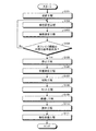
つぎに、本発明の実施の形態に係る光ファイバ製造装置1の立ち上げ方法について説明する。図2は、本発明の実施の形態に係る光ファイバ製造装置の立ち上げ方法の一例を示すフロー図である。図3は、光ファイバ製造装置の立ち上げ方法におけるダイスの退避工程からセット工程までの各工程を説明する模式図である。図4は、光ファイバ製造装置の立ち上げ方法におけるダイスの線通し工程から光ファイバの巻取準備工程までの各工程を説明する模式図である。なお、図3、4では、各工程の説明をし易くするために、硬化機構6、入力部9、記憶部10及び表示部11の図示は省略している。
2 線引炉
2a ヒータ
3 牽引機構
3a キャプスタン
3b 駆動部
3c 無端ベルト
4 ダイス
4a 挿通孔
5 移送機構
5a 支持部
5b 駆動部
6 硬化機構
7 測定器
7a 光源部
7b 受光部
8 把持機構
9 入力部
10 記憶部
11 表示部
12 制御部
15 光ファイバ母材
16 ガラス光ファイバ
16a、16b 切断端部
16c 接合部分
17 光ファイバ
19 接合部材
100 光ファイバ製造装置
101 ダイス
102a、102b 小型キャプスタン
103 キャプスタン
104 無端ベルト
105 吸引装置
110 ガラス光ファイバ
L1 光
R1、R10 光ファイバ通過経路
Claims (9)
- 光ファイバ母材を加熱溶融する加熱炉と、
前記加熱炉によって加熱溶融された前記光ファイバ母材からガラス光ファイバを引き出して前記ガラス光ファイバの外径を調整し、且つ、外径調整後の前記ガラス光ファイバを線引きする牽引機構と、
外径調整後の前記ガラス光ファイバの外周に所定の樹脂を塗布する塗布機構と、
前記ガラス光ファイバの通過経路から前記塗布機構を復帰可能に退避させる移送機構と、
を備えることを特徴とする光ファイバ製造装置。 - 前記加熱炉と前記塗布機構との間に、前記ガラス光ファイバの外径を測定する測定器を備えることを特徴とする請求項1に記載の光ファイバ製造装置。
- 前記測定器によって測定された前記ガラス光ファイバの外径に基づいて前記牽引機構を制御する制御部を備えることを特徴とする請求項2に記載の光ファイバ製造装置。
- 前記測定器は、外径調整後の前記ガラス光ファイバの通過位置を更に測定し、
前記制御部は、測定された外径調整後の前記ガラス光ファイバの通過位置をもとに、前記塗布機構の復帰位置を制御することを特徴とする請求項3に記載の光ファイバ製造装置。 - 前記光ファイバ母材を把持して、前記加熱炉に対する前記光ファイバ母材の相対位置を調整する把持機構を備え、
前記制御部は、前記ガラス光ファイバの引き出しを停止させた後、前記光ファイバ母材を前記加熱炉のヒータから離すように前記把持機構を制御することを特徴とする請求項3又は4に記載の光ファイバ製造装置。 - 加熱炉によって光ファイバ母材を加熱溶融し、
牽引機構によって前記光ファイバ母材から所望の外径を有するガラス光ファイバを線引きし、
線引きされた前記ガラス光ファイバの外周に所定の樹脂を塗布機構によって塗布し、前記所定の樹脂の硬化によって外周に被覆層が形成された光ファイバを製造する光ファイバ製造装置の立ち上げ方法であって、
前記牽引機構によって前記光ファイバ母材から引き出される前記ガラス光ファイバの通過経路から、前記塗布機構を退避させる退避工程と、
前記牽引機構によって前記光ファイバ母材からガラス光ファイバを引き出して前記ガラス光ファイバの外径を調整する線径調整工程と、
外径調整後の前記ガラス光ファイバの通過経路内に前記塗布機構を復帰させるセット工程と、
を含むことを特徴とする光ファイバ製造装置の立ち上げ方法。 - 前記牽引機構によって調整される前記ガラス光ファイバの外径を測定する線径測定工程と、
測定された前記ガラス光ファイバの外径が前記塗布機構の挿通孔の直径未満である場合、前記牽引機構による前記ガラス光ファイバの引き出しを停止する停止工程と、
前記引き出しが停止された外径調整後の前記ガラス光ファイバを切断する切断工程と、
を含み、前記セット工程は、外径調整後の前記ガラス光ファイバが切断された後に、外径調整後の前記ガラス光ファイバの通過経路内に前記塗布機構を復帰させることを特徴とする請求項6に記載の光ファイバ製造装置の立ち上げ方法。 - 前記牽引機構による外径調整後の前記ガラス光ファイバの通過位置を測定する位置測定工程を更に含み、
前記セット工程は、測定された外径調整後の前記ガラス光ファイバの通過位置をもとに、前記塗布機構の復帰位置を制御することを特徴とする請求項6又は7に記載の光ファイバ製造装置の立ち上げ方法。 - 前記加熱炉に対する前記光ファイバ母材の相対位置は、前記ガラス光ファイバの引き出しを停止した後に、前記光ファイバ母材を前記加熱炉のヒータから離すように調整されることを特徴とする請求項7又は請求項7を引用する請求項8に記載の光ファイバ製造装置の立ち上げ方法。
Priority Applications (5)
| Application Number | Priority Date | Filing Date | Title |
|---|---|---|---|
| JP2017072608A JP6574455B2 (ja) | 2017-03-31 | 2017-03-31 | 光ファイバ製造装置及びその立ち上げ方法 |
| EP18778253.7A EP3604244B1 (en) | 2017-03-31 | 2018-03-26 | Optical fiber manufacturing apparatus and method of starting optical fiber manufacturing apparatus |
| PCT/JP2018/012017 WO2018181118A1 (ja) | 2017-03-31 | 2018-03-26 | 光ファイバ製造装置及びその立ち上げ方法 |
| CN201880020735.7A CN110520394B (zh) | 2017-03-31 | 2018-03-26 | 光纤制造装置及其调机方法 |
| US16/575,641 US10641945B2 (en) | 2017-03-31 | 2019-09-19 | Optical fiber manufacturing apparatus and method of starting optical fiber manufacturing apparatus |
Applications Claiming Priority (1)
| Application Number | Priority Date | Filing Date | Title |
|---|---|---|---|
| JP2017072608A JP6574455B2 (ja) | 2017-03-31 | 2017-03-31 | 光ファイバ製造装置及びその立ち上げ方法 |
Publications (2)
| Publication Number | Publication Date |
|---|---|
| JP2018172249A JP2018172249A (ja) | 2018-11-08 |
| JP6574455B2 true JP6574455B2 (ja) | 2019-09-11 |
Family
ID=63676055
Family Applications (1)
| Application Number | Title | Priority Date | Filing Date |
|---|---|---|---|
| JP2017072608A Active JP6574455B2 (ja) | 2017-03-31 | 2017-03-31 | 光ファイバ製造装置及びその立ち上げ方法 |
Country Status (5)
| Country | Link |
|---|---|
| US (1) | US10641945B2 (ja) |
| EP (1) | EP3604244B1 (ja) |
| JP (1) | JP6574455B2 (ja) |
| CN (1) | CN110520394B (ja) |
| WO (1) | WO2018181118A1 (ja) |
Families Citing this family (2)
| Publication number | Priority date | Publication date | Assignee | Title |
|---|---|---|---|---|
| CN111499182B (zh) * | 2020-03-23 | 2021-09-14 | 中国科学院西安光学精密机械研究所 | 一种分布式侧面泵浦耦合光纤的在线拉制制备方法及系统 |
| CN112028470A (zh) * | 2020-09-18 | 2020-12-04 | 程笔云 | 一种量子保密通信传输光纤生产加工工艺 |
Family Cites Families (15)
| Publication number | Priority date | Publication date | Assignee | Title |
|---|---|---|---|---|
| JPH04357139A (ja) * | 1991-05-29 | 1992-12-10 | Opt D D Melco Lab:Kk | 光ファイバの被覆装置 |
| JPH06234553A (ja) * | 1993-02-12 | 1994-08-23 | Furukawa Electric Co Ltd:The | 着色光ファイバの製造方法 |
| JP3169161B2 (ja) * | 1995-08-15 | 2001-05-21 | 住友電気工業株式会社 | 光ファイバ被覆方法およびその装置 |
| JPH10330133A (ja) * | 1997-05-29 | 1998-12-15 | Furukawa Electric Co Ltd:The | 被覆光ファイバの製造装置 |
| US7197898B2 (en) * | 2000-12-04 | 2007-04-03 | Sheng-Guo Wang | Robust diameter-controlled optical fiber during optical fiber drawing process |
| JP2003335543A (ja) * | 2002-05-16 | 2003-11-25 | Sumitomo Electric Ind Ltd | 光ファイバの線引方法及びその装置 |
| JP2005075664A (ja) * | 2003-08-29 | 2005-03-24 | Sumitomo Electric Ind Ltd | 光ファイバの線引方法 |
| JP2005097051A (ja) * | 2003-09-25 | 2005-04-14 | Sumitomo Electric Ind Ltd | 光ファイバの線引装置 |
| JP4442493B2 (ja) * | 2005-04-07 | 2010-03-31 | 住友電気工業株式会社 | 光ファイバの製造方法。 |
| WO2008139570A1 (ja) * | 2007-05-08 | 2008-11-20 | The Furukawa Electric Co., Ltd. | 光ファイバの製造方法および光ファイバの製造装置 |
| CN101970366B (zh) * | 2008-03-05 | 2013-08-07 | 古河电气工业株式会社 | 玻璃光纤的处理装置、处理方法以及光纤的制造方法和线牵引方法 |
| JP5372082B2 (ja) * | 2011-08-12 | 2013-12-18 | 株式会社フジクラ | 光ファイバ素線の製造方法および製造装置 |
| JP5903123B2 (ja) * | 2014-04-07 | 2016-04-13 | 株式会社フジクラ | 光ファイバ素線の製造方法および製造装置 |
| CN104944800A (zh) * | 2015-05-29 | 2015-09-30 | 成都亨通光通信有限公司 | 光纤成形方法 |
| CN105271826B (zh) * | 2015-11-03 | 2018-11-23 | 江苏通鼎光棒有限公司 | 一种改善光纤筛选强度和涂覆同心度的装置及方法 |
-
2017
- 2017-03-31 JP JP2017072608A patent/JP6574455B2/ja active Active
-
2018
- 2018-03-26 WO PCT/JP2018/012017 patent/WO2018181118A1/ja active Application Filing
- 2018-03-26 EP EP18778253.7A patent/EP3604244B1/en active Active
- 2018-03-26 CN CN201880020735.7A patent/CN110520394B/zh active Active
-
2019
- 2019-09-19 US US16/575,641 patent/US10641945B2/en active Active
Also Published As
| Publication number | Publication date |
|---|---|
| EP3604244A1 (en) | 2020-02-05 |
| EP3604244A4 (en) | 2020-12-30 |
| JP2018172249A (ja) | 2018-11-08 |
| CN110520394A (zh) | 2019-11-29 |
| WO2018181118A1 (ja) | 2018-10-04 |
| US10641945B2 (en) | 2020-05-05 |
| EP3604244B1 (en) | 2024-01-17 |
| CN110520394B (zh) | 2022-04-26 |
| US20200012038A1 (en) | 2020-01-09 |
Similar Documents
| Publication | Publication Date | Title |
|---|---|---|
| JP6574455B2 (ja) | 光ファイバ製造装置及びその立ち上げ方法 | |
| CN103303743A (zh) | 光纤绕线装置 | |
| US10399289B2 (en) | Deposition head for depositing an impregnated fiber tape, and a device for placing such a tape | |
| CS234036B2 (en) | Method of replacement of first empty coil with belt material by second new coil and equipment for its application | |
| JP2020520866A (ja) | ボビンに巻かれた材料シートを供給および接合するための方法および装置 | |
| KR20000052387A (ko) | 종이웨브의 접속부형성장치와 방법 | |
| KR20160058799A (ko) | 차량 글레이징 패널 컷아웃 방법 | |
| US7044417B2 (en) | High speed transfer takeup | |
| CN110589557A (zh) | 多种接头式棉花包装膜接膜设备及其应用 | |
| JP2001520157A (ja) | 可撓性ウエブ加工機の反故紙の除去および制御方法と装置 | |
| JP3794955B2 (ja) | 紙継装置の前準備方法及び紙継装置並びにコルゲートマシン | |
| CN109512017A (zh) | 操纵卷纸完成绝对位置拼接的装置及方法 | |
| KR20030044012A (ko) | 광섬유의 프루프 시험방법 및 장치 | |
| JPH08105828A (ja) | 光ファイバの引張り試験装置 | |
| JPH0769539A (ja) | 線材巻付け装置 | |
| WO2004011236A1 (ja) | タイヤ構成部材の貼付装置 | |
| TW525325B (en) | A method and an arrangement for supplying optical fibers | |
| CN220245095U (zh) | 光纤盘绕装置 | |
| JP4300993B2 (ja) | 光ファイバの製造方法 | |
| JPS63135202A (ja) | シ−ト状基材の継ぎ接着方法 | |
| JP2001287926A (ja) | 線引き口出し方法及び線引き装置 | |
| JP2006119160A (ja) | 線条体の接合方法及び接合装置 | |
| JP4843155B2 (ja) | ワインダ及び製紙設備 | |
| JPH08119660A (ja) | 光ファイバの連続製造装置 | |
| JP2023129967A (ja) | 光ファイバの製造方法 |
Legal Events
| Date | Code | Title | Description |
|---|---|---|---|
| A621 | Written request for application examination |
Free format text: JAPANESE INTERMEDIATE CODE: A621 Effective date: 20180807 |
|
| TRDD | Decision of grant or rejection written | ||
| A01 | Written decision to grant a patent or to grant a registration (utility model) |
Free format text: JAPANESE INTERMEDIATE CODE: A01 Effective date: 20190723 |
|
| A61 | First payment of annual fees (during grant procedure) |
Free format text: JAPANESE INTERMEDIATE CODE: A61 Effective date: 20190816 |
|
| R151 | Written notification of patent or utility model registration |
Ref document number: 6574455 Country of ref document: JP Free format text: JAPANESE INTERMEDIATE CODE: R151 |
|
| S531 | Written request for registration of change of domicile |
Free format text: JAPANESE INTERMEDIATE CODE: R313531 |
|
| R350 | Written notification of registration of transfer |
Free format text: JAPANESE INTERMEDIATE CODE: R350 |