JP6000803B2 - プローブ支持装置 - Google Patents
プローブ支持装置 Download PDFInfo
- Publication number
- JP6000803B2 JP6000803B2 JP2012237939A JP2012237939A JP6000803B2 JP 6000803 B2 JP6000803 B2 JP 6000803B2 JP 2012237939 A JP2012237939 A JP 2012237939A JP 2012237939 A JP2012237939 A JP 2012237939A JP 6000803 B2 JP6000803 B2 JP 6000803B2
- Authority
- JP
- Japan
- Prior art keywords
- probe
- probe support
- support device
- arm
- ultrasonic
- Prior art date
- Legal status (The legal status is an assumption and is not a legal conclusion. Google has not performed a legal analysis and makes no representation as to the accuracy of the status listed.)
- Active
Links
Images


Classifications
-
- A—HUMAN NECESSITIES
- A61—MEDICAL OR VETERINARY SCIENCE; HYGIENE
- A61B—DIAGNOSIS; SURGERY; IDENTIFICATION
- A61B5/00—Measuring for diagnostic purposes; Identification of persons
- A61B5/68—Arrangements of detecting, measuring or recording means, e.g. sensors, in relation to patient
- A61B5/6801—Arrangements of detecting, measuring or recording means, e.g. sensors, in relation to patient specially adapted to be attached to or worn on the body surface
- A61B5/683—Means for maintaining contact with the body
- A61B5/6835—Supports or holders, e.g., articulated arms
-
- A—HUMAN NECESSITIES
- A61—MEDICAL OR VETERINARY SCIENCE; HYGIENE
- A61B—DIAGNOSIS; SURGERY; IDENTIFICATION
- A61B8/00—Diagnosis using ultrasonic, sonic or infrasonic waves
- A61B8/42—Details of probe positioning or probe attachment to the patient
- A61B8/4209—Details of probe positioning or probe attachment to the patient by using holders, e.g. positioning frames
- A61B8/4218—Details of probe positioning or probe attachment to the patient by using holders, e.g. positioning frames characterised by articulated arms
-
- A—HUMAN NECESSITIES
- A61—MEDICAL OR VETERINARY SCIENCE; HYGIENE
- A61B—DIAGNOSIS; SURGERY; IDENTIFICATION
- A61B5/00—Measuring for diagnostic purposes; Identification of persons
- A61B5/0093—Detecting, measuring or recording by applying one single type of energy and measuring its conversion into another type of energy
- A61B5/0095—Detecting, measuring or recording by applying one single type of energy and measuring its conversion into another type of energy by applying light and detecting acoustic waves, i.e. photoacoustic measurements
-
- A—HUMAN NECESSITIES
- A61—MEDICAL OR VETERINARY SCIENCE; HYGIENE
- A61B—DIAGNOSIS; SURGERY; IDENTIFICATION
- A61B8/00—Diagnosis using ultrasonic, sonic or infrasonic waves
- A61B8/42—Details of probe positioning or probe attachment to the patient
- A61B8/4245—Details of probe positioning or probe attachment to the patient involving determining the position of the probe, e.g. with respect to an external reference frame or to the patient
-
- A—HUMAN NECESSITIES
- A61—MEDICAL OR VETERINARY SCIENCE; HYGIENE
- A61B—DIAGNOSIS; SURGERY; IDENTIFICATION
- A61B8/00—Diagnosis using ultrasonic, sonic or infrasonic waves
- A61B8/44—Constructional features of the ultrasonic, sonic or infrasonic diagnostic device
- A61B8/4444—Constructional features of the ultrasonic, sonic or infrasonic diagnostic device related to the probe
Description
支持することが可能なプローブ支持装置を提供することができる。
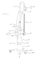
図1は、本発明の実施例1に係るプローブ支持装置の外観図である。プローブ支持装置1は、基台部2、アーム部3、非変形部4、変形部5を主たる構成とする。非変形部4と変形部5を合わせてプローブ支持部とも呼ぶ。
その結果、コストを抑制しつつ、超音波プローブの使用状態に応じて超音波プローブを支持することができ、ユーザーの負担を軽減することが可能となる。
実施例2では、プローブ支持部(特に変形部)の剛性により、ユーザーが所定の値以上の距離を持ち上げることによって前記アーム部が持ち上がるプローブ支持装置の例について説明する。
実施例3では、アーム部の俯仰に応じて、前記基台部が伸縮する本発明のプローブ支持装置の例について説明する。
実施例4では、所定の角度以上の折れ曲がりを規制する構造である本発明の実施例4に係るプローブ支持装置について説明する。
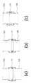
士が傾き、図7(b)の屈曲した状態に至る。図7(b)では、部材51内壁の凸部と部材52外壁の凸部が突き当たるため、それ以上屈曲することができない状態である。この屈曲を規制する角度については、部材51および部材52の直径や凸部の間隔等を変更することで調整することが可能である。
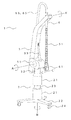
実施例5では、光音響装置に用いられる光音響プローブに本発明のプローブ支持装置を適用した例について説明する。ハンドヘルド型の光音響プローブを用いる場合、プローブにおいて、レーザーなどの光源から導かれたパルス光を被検体に照射する機構と、被検体内の吸収体から発生した光音響波(典型的には超音波)を検出する機構が必要となる。さらに、光音響波を検出する機構が超音波を送信する機構を兼ねる、あるいは超音波を送信する機構を別に設けることにより、超音波プローブに光音響プローブを兼ねさせることもできる。
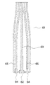
光音響プローブ61は、変形部51の下端に接続され、ケーブル63および光ファイバー65は、変形部51および非変形部4の内部を通して光音響装置本体に接続される。
の必要性が高い光ファイバーを用いる光音響プローブを良好に使用できる。
さらに光音響プローブは重量が大きいことから、ユーザーの負担を軽減する効果が大きい。
Claims (13)
- 基台部と、
前記基台部の上端に俯仰可能かつ水平方向に回動可能に接続されたアーム部と、
前記アーム部が前記基台部と接続する部分に対して前記アーム部の逆側に接続されたプローブ支持部と、
を有するプローブ支持装置であって、
前記プローブ支持部は変形部と非変形部で構成され、前記非変形部は前記アーム部が俯仰する際の回転軸と平行な軸に対して回動可能に前記アーム部に接続される
ことを特徴とするプローブ支持装置。 - 前記プローブ支持部は、前記基台部と接続する部分とは反対側における前記アーム部の先端に接続されている
ことを特徴とする請求項1に記載のプローブ支持装置。 - 前記変形部が前記非変形部と接続する部分に対して前記変形部の逆側にプローブが接続される
ことを特徴とする請求項1に記載のプローブ支持装置。 - 前記プローブは、前記非変形部と接続する部分とは反対側における前記変形部の先端に接続されている
ことを特徴とする請求項3に記載のプローブ支持装置。 - 前記変形部は、前記非変形部と接続する部分から鉛直方向に沿って垂下した状態となることを特徴とする請求項1ないし4のいずれか1項に記載のプローブ支持装置。
- ユーザーが前記プローブを所定の値以上の距離を持ち上げることにより、前記プローブ支持部の剛性により前記プローブの上昇に応じて前記アーム部が持ち上がる
ことを特徴とする請求項3または4に記載のプローブ支持装置。 - 前記プローブ支持部は、所定の値以上の力が加えられると前記アーム部に前記力を伝達する
ことを特徴とする請求項1ないし6のいずれか1項に記載のプローブ支持装置。 - 前記アーム部の俯仰に応じて、前記基台部が伸縮する
ことを特徴とする請求項1ないし7のいずれか1項に記載のプローブ支持装置。 - 前記変形部は、所定の角度以上の折れ曲がりを規制する構造である
ことを特徴とする請求項1ないし8のいずれか1項に記載のプローブ支持装置。 - 請求項1ないし9のいずれか1項に記載のプローブ支持装置と、
前記プローブ支持装置のプローブ支持部に接続され、被検体に超音波を送信するとともに、前記被検体から反射した超音波を受信する超音波プローブと、
前記受信した超音波に基づき前記被検体の情報を取得する情報処理装置と、
を有することを特徴とする超音波装置。 - 前記情報処理装置と前記超音波プローブとを接続し、前記超音波プローブからの受信信号を前記情報処理装置に伝送するケーブルをさらに有し、
前記ケーブルは、前記情報処理装置から前記超音波プローブに向かって、前記アーム部、前記非変形部、前記変形部の順に、前記アーム部、前記非変形部、前記変形部に沿って延在する
ことを特徴とする請求項10に記載の超音波装置。 - 請求項1ないし9のいずれか1項に記載のプローブ支持装置と、
前記プローブ支持装置のプローブ支持部に接続され、光を照射された被検体から発生する光音響波を受信する光音響プローブと、
前記受信した光音響波に基づき前記被検体の情報を取得する情報処理装置と、
を有することを特徴とする光音響装置。 - 前記光を照射する光源と、
前記光を前記光源から前記光音響プローブに導く光ファイバーと、
をさらに有し、
前記光ファイバーは、前記光源から前記光音響プローブに向かって、前記アーム部、前記非変形部、前記変形部の順に、前記アーム部、前記非変形部、前記変形部に沿って延在する
ことを特徴とする請求項12に記載の光音響装置。
Priority Applications (4)
| Application Number | Priority Date | Filing Date | Title |
|---|---|---|---|
| JP2012237939A JP6000803B2 (ja) | 2012-10-29 | 2012-10-29 | プローブ支持装置 |
| US14/433,731 US9615795B2 (en) | 2012-10-29 | 2013-10-08 | Probe support apparatus |
| PCT/JP2013/005972 WO2014068853A1 (en) | 2012-10-29 | 2013-10-08 | Probe support apparatus |
| US15/449,106 US20170172506A1 (en) | 2012-10-29 | 2017-03-03 | Probe support apparatus |
Applications Claiming Priority (1)
| Application Number | Priority Date | Filing Date | Title |
|---|---|---|---|
| JP2012237939A JP6000803B2 (ja) | 2012-10-29 | 2012-10-29 | プローブ支持装置 |
Publications (3)
| Publication Number | Publication Date |
|---|---|
| JP2014087399A JP2014087399A (ja) | 2014-05-15 |
| JP2014087399A5 JP2014087399A5 (ja) | 2015-11-12 |
| JP6000803B2 true JP6000803B2 (ja) | 2016-10-05 |
Family
ID=49486622
Family Applications (1)
| Application Number | Title | Priority Date | Filing Date |
|---|---|---|---|
| JP2012237939A Active JP6000803B2 (ja) | 2012-10-29 | 2012-10-29 | プローブ支持装置 |
Country Status (3)
| Country | Link |
|---|---|
| US (2) | US9615795B2 (ja) |
| JP (1) | JP6000803B2 (ja) |
| WO (1) | WO2014068853A1 (ja) |
Families Citing this family (4)
| Publication number | Priority date | Publication date | Assignee | Title |
|---|---|---|---|---|
| JP6570341B2 (ja) | 2015-06-30 | 2019-09-04 | キヤノン株式会社 | 放射線ct装置およびその制御方法 |
| JP6299738B2 (ja) * | 2015-12-24 | 2018-03-28 | トヨタ自動車株式会社 | 非接触送電装置及び電力伝送システム |
| KR20190102598A (ko) * | 2018-02-26 | 2019-09-04 | 삼성메디슨 주식회사 | 초음파 진단 장치 및 이를 위한 케이블 지지 장치 |
| US20220313211A1 (en) * | 2021-04-05 | 2022-10-06 | Mahmoud I. Eltorai | Ultrasound support device |
Family Cites Families (13)
| Publication number | Priority date | Publication date | Assignee | Title |
|---|---|---|---|---|
| JP2768517B2 (ja) * | 1989-12-19 | 1998-06-25 | アロカ株式会社 | 超音波診断装置用ケーブルハンガー |
| JPH0475646A (ja) * | 1990-07-17 | 1992-03-10 | Toshiba Corp | 超音波診断装置 |
| JPH04210051A (ja) * | 1990-12-05 | 1992-07-31 | Toshiba Corp | ケーブルガイド装置 |
| JPH0584242A (ja) * | 1991-09-30 | 1993-04-06 | Fujitsu Ltd | 超音波診断装置 |
| JPH0670927A (ja) * | 1992-08-27 | 1994-03-15 | Toshiba Corp | 超音波診断装置 |
| IL107523A (en) * | 1993-11-07 | 2000-01-31 | Ultraguide Ltd | Articulated needle guide for ultrasound imaging and method of using same |
| JPH07178097A (ja) * | 1993-12-22 | 1995-07-18 | Toshiba Corp | 超音波診断装置 |
| JP2005312577A (ja) * | 2004-04-28 | 2005-11-10 | Ge Medical Systems Global Technology Co Llc | 超音波診断装置 |
| US7806862B2 (en) * | 2008-05-02 | 2010-10-05 | Molnar James M | Regional anesthesia system and cart |
| US9528966B2 (en) * | 2008-10-23 | 2016-12-27 | Washington University | Reflection-mode photoacoustic tomography using a flexibly-supported cantilever beam |
| US20110213247A1 (en) * | 2010-01-08 | 2011-09-01 | Hexagon Metrology, Inc. | Articulated arm with imaging device |
| JP6014329B2 (ja) | 2012-01-17 | 2016-10-25 | キヤノン株式会社 | X線撮影装置 |
| JP5917162B2 (ja) | 2012-01-19 | 2016-05-11 | キヤノン株式会社 | X線撮影装置 |
-
2012
- 2012-10-29 JP JP2012237939A patent/JP6000803B2/ja active Active
-
2013
- 2013-10-08 US US14/433,731 patent/US9615795B2/en active Active
- 2013-10-08 WO PCT/JP2013/005972 patent/WO2014068853A1/en active Application Filing
-
2017
- 2017-03-03 US US15/449,106 patent/US20170172506A1/en not_active Abandoned
Also Published As
| Publication number | Publication date |
|---|---|
| US20170172506A1 (en) | 2017-06-22 |
| US9615795B2 (en) | 2017-04-11 |
| JP2014087399A (ja) | 2014-05-15 |
| US20150272502A1 (en) | 2015-10-01 |
| WO2014068853A1 (en) | 2014-05-08 |
Similar Documents
| Publication | Publication Date | Title |
|---|---|---|
| JP6000803B2 (ja) | プローブ支持装置 | |
| JP6486068B2 (ja) | 被検部位情報取得装置 | |
| US10653377B2 (en) | Breast computed tomography system comprising a gripper | |
| JP6274819B2 (ja) | 被検部位情報取得装置 | |
| EP3188646B1 (en) | Object information acquiring apparatus | |
| JP6648919B2 (ja) | 被検体情報取得装置 | |
| US20180008148A1 (en) | Subject information acquisition apparatus | |
| US11058357B2 (en) | Acoustic wave apparatus and control method thereof | |
| JP2016101369A (ja) | 光音響装置および光音響装置の制御方法 | |
| WO2016051749A1 (en) | Object information acquiring apparatus | |
| US20150105649A1 (en) | Subject information acquisition apparatus | |
| US10288719B2 (en) | Object information acquiring apparatus and information processing apparatus | |
| JP2016002373A (ja) | 被検体情報取得装置 | |
| JP2013220171A (ja) | イメージングプローブ | |
| JP2017077411A (ja) | 被検体情報取得装置 | |
| JP5250473B2 (ja) | 医療用診療装置 | |
| JP6497896B2 (ja) | 情報取得装置 | |
| JP6444126B2 (ja) | 光音響装置および光音響波の測定方法 | |
| JP2017046763A (ja) | 光音響波測定装置 | |
| US11526982B2 (en) | Image processing device, image processing method, and program | |
| JP2018079020A (ja) | 音響波受信装置およびフロート | |
| JP6742700B2 (ja) | 被検体支持装置および被検体情報取得装置 | |
| JP2015029684A (ja) | 被検部位情報取得装置 | |
| JP2017046762A (ja) | 被検体情報取得装置および被検体情報取得装置の駆動方法 | |
| JP2016144692A (ja) | イメージングプローブ |
Legal Events
| Date | Code | Title | Description |
|---|---|---|---|
| A521 | Request for written amendment filed |
Free format text: JAPANESE INTERMEDIATE CODE: A523 Effective date: 20150918 |
|
| A621 | Written request for application examination |
Free format text: JAPANESE INTERMEDIATE CODE: A621 Effective date: 20150918 |
|
| TRDD | Decision of grant or rejection written | ||
| A01 | Written decision to grant a patent or to grant a registration (utility model) |
Free format text: JAPANESE INTERMEDIATE CODE: A01 Effective date: 20160802 |
|
| A61 | First payment of annual fees (during grant procedure) |
Free format text: JAPANESE INTERMEDIATE CODE: A61 Effective date: 20160831 |
|
| R151 | Written notification of patent or utility model registration |
Ref document number: 6000803 Country of ref document: JP Free format text: JAPANESE INTERMEDIATE CODE: R151 |