JP6000803B2 - Probe support device - Google Patents
Probe support device Download PDFInfo
- Publication number
- JP6000803B2 JP6000803B2 JP2012237939A JP2012237939A JP6000803B2 JP 6000803 B2 JP6000803 B2 JP 6000803B2 JP 2012237939 A JP2012237939 A JP 2012237939A JP 2012237939 A JP2012237939 A JP 2012237939A JP 6000803 B2 JP6000803 B2 JP 6000803B2
- Authority
- JP
- Japan
- Prior art keywords
- probe
- probe support
- support device
- arm
- ultrasonic
- Prior art date
- Legal status (The legal status is an assumption and is not a legal conclusion. Google has not performed a legal analysis and makes no representation as to the accuracy of the status listed.)
- Active
Links
Images


Classifications
-
- A—HUMAN NECESSITIES
- A61—MEDICAL OR VETERINARY SCIENCE; HYGIENE
- A61B—DIAGNOSIS; SURGERY; IDENTIFICATION
- A61B5/00—Measuring for diagnostic purposes; Identification of persons
- A61B5/68—Arrangements of detecting, measuring or recording means, e.g. sensors, in relation to patient
- A61B5/6801—Arrangements of detecting, measuring or recording means, e.g. sensors, in relation to patient specially adapted to be attached to or worn on the body surface
- A61B5/683—Means for maintaining contact with the body
- A61B5/6835—Supports or holders, e.g., articulated arms
-
- A—HUMAN NECESSITIES
- A61—MEDICAL OR VETERINARY SCIENCE; HYGIENE
- A61B—DIAGNOSIS; SURGERY; IDENTIFICATION
- A61B8/00—Diagnosis using ultrasonic, sonic or infrasonic waves
- A61B8/42—Details of probe positioning or probe attachment to the patient
- A61B8/4209—Details of probe positioning or probe attachment to the patient by using holders, e.g. positioning frames
- A61B8/4218—Details of probe positioning or probe attachment to the patient by using holders, e.g. positioning frames characterised by articulated arms
-
- A—HUMAN NECESSITIES
- A61—MEDICAL OR VETERINARY SCIENCE; HYGIENE
- A61B—DIAGNOSIS; SURGERY; IDENTIFICATION
- A61B5/00—Measuring for diagnostic purposes; Identification of persons
- A61B5/0093—Detecting, measuring or recording by applying one single type of energy and measuring its conversion into another type of energy
- A61B5/0095—Detecting, measuring or recording by applying one single type of energy and measuring its conversion into another type of energy by applying light and detecting acoustic waves, i.e. photoacoustic measurements
-
- A—HUMAN NECESSITIES
- A61—MEDICAL OR VETERINARY SCIENCE; HYGIENE
- A61B—DIAGNOSIS; SURGERY; IDENTIFICATION
- A61B8/00—Diagnosis using ultrasonic, sonic or infrasonic waves
- A61B8/42—Details of probe positioning or probe attachment to the patient
- A61B8/4245—Details of probe positioning or probe attachment to the patient involving determining the position of the probe, e.g. with respect to an external reference frame or to the patient
-
- A—HUMAN NECESSITIES
- A61—MEDICAL OR VETERINARY SCIENCE; HYGIENE
- A61B—DIAGNOSIS; SURGERY; IDENTIFICATION
- A61B8/00—Diagnosis using ultrasonic, sonic or infrasonic waves
- A61B8/44—Constructional features of the ultrasonic, sonic or infrasonic diagnostic device
- A61B8/4444—Constructional features of the ultrasonic, sonic or infrasonic diagnostic device related to the probe
Description
本発明は、プローブ支持装置に関する。 The present invention relates to a probe support device.
超音波装置、とりわけ超音波プローブをユーザーが手で持って操作するタイプのハンドヘルド型の装置においては、本体にケーブルで接続された超音波プローブを検査部位に押し当てて検査が行われる。検査の際、ケーブルが床や被検者に接触すること、あるいは、ベッド等に引っかかることを防止するため、スタンドやアームにケーブルを係止し、上部から超音波プローブを吊架するプローブ支持装置が知られている。 In an ultrasonic device, in particular, a hand-held type device in which an ultrasonic probe is operated by a user's hand, an ultrasonic probe connected to a main body with a cable is pressed against an inspection site. In order to prevent the cable from coming into contact with the floor or the subject or being caught on the bed during the inspection, there is a probe support device that locks the cable to the stand or arm and suspends the ultrasonic probe from above. Are known.
特許文献1には、折り畳み式アームの内側に超音波プローブのケーブルを添わせ、アーム上端から超音波プローブを吊架する、ケーブルガイド装置が開示されている。しかし、特許文献1に開示されるケーブルガイド装置においては、超音波プローブの使用状態にあわせて、アームの位置調整を予め手作業で行わなければならず、操作が煩雑であるという課題が存在する。
特許文献2には、センサにより超音波プローブの位置を特定し、アーム上端のケーブル支持位置が超音波プローブの垂直上方に位置するようにモーター等の駆動装置によって制御する、超音波装置が開示されている。しかし、特許文献2に開示される超音波装置においては、センサやモーター等の駆動装置が必要であり、コストがかかるという課題が存在する。
また、特許文献3のような、光音響効果を利用した検査を行う光音響装置においても、光音響プローブの支持に関して同様の課題が存在する。
In the photoacoustic apparatus that performs inspection using the photoacoustic effect as in
本発明は上記課題に鑑みてなされたものであり、コストを抑制しつつ、プローブが被検部位の略直上に位置するように支持することが可能なプローブ支持装置を提供することを目的とする。 The present invention has been made in view of the above problems, and an object of the present invention is to provide a probe support device capable of supporting a probe so as to be positioned substantially immediately above a test site while suppressing cost. .
本発明は以下の構成を採用する。すなわち、基台部と、前記基台部の上端に俯仰可能かつ水平方向に回動可能に接続されたアーム部と、前記アーム部が前記基台部と接続する部分に対して前記アーム部の逆側に接続されたプローブ支持部と、を有するプローブ支持装置であって、前記プローブ支持部は変形部と非変形部で構成され、前記非変形部は前記アーム部が俯仰する際の回転軸と平行な軸に対して回動可能に前記アーム部に接続されることを特徴とするプローブ支持装置である。 The present invention employs the following configuration. That is, the base part, the arm part connected to the upper end of the base part so as to be able to be lifted and rotated in the horizontal direction, and the part of the arm part with respect to the part where the arm part is connected to the base part A probe support device having a probe support portion connected to the opposite side , wherein the probe support portion is composed of a deformable portion and a non-deformable portion, and the non-deformable portion is a rotating shaft when the arm portion is raised and lowered The probe support device is connected to the arm portion so as to be rotatable with respect to an axis parallel to the probe.
本発明によれば、コストを抑制しつつ、プローブが被検部位の略直上に位置するように
支持することが可能なプローブ支持装置を提供することができる。
ADVANTAGE OF THE INVENTION According to this invention, the probe support apparatus which can be supported so that a probe may be located substantially right above a test site | part can be provided, suppressing cost.
以下に図面を参照しつつ、本発明の好適な実施の形態について説明する。ただし、以下に記載されている構成部品の寸法、材質、形状およびそれらの相対配置などは、発明が適用される装置の構成や各種条件により適宜変更されるべきものであり、この発明の範囲を以下の記載に限定する趣旨のものではない。 Hereinafter, preferred embodiments of the present invention will be described with reference to the drawings. However, the dimensions, materials, shapes, and relative arrangements of the components described below should be changed as appropriate according to the configuration of the apparatus to which the invention is applied and various conditions. It is not intended to limit the following description.
本発明のプローブ支持装置は、例えば超音波装置用の超音波プローブや、光音響装置用の光音響プローブに適用できる。前者の超音波装置は、プローブ内の素子から被検体に超音波を送信し、被検体内部で反射したエコー波をプローブで受信して、被検体情報を画像データとして取得する。後者の光音響装置は、被検体に光を照射したときに光音響効果により発生する音響波(光音響波または光超音波とも呼ぶ)をプローブで受信して、被検体情報を画像データとして取得する。 The probe support device of the present invention can be applied to, for example, an ultrasonic probe for an ultrasonic device and a photoacoustic probe for a photoacoustic device. The former ultrasonic device transmits ultrasonic waves from the elements in the probe to the subject, receives echo waves reflected inside the subject with the probe, and acquires subject information as image data. The latter photoacoustic apparatus receives acoustic waves (also referred to as photoacoustic waves or photoacoustic waves) generated by the photoacoustic effect when the subject is irradiated with light, and acquires subject information as image data. To do.
前者の超音波装置の場合、取得される被検体情報とは、被検体内部の組織の音響インピーダンスの違いを反映した情報である。後者の光音響装置の場合、取得される被検体情報とは、光照射によって生じた音響波の発生源分布、被検体内の初期音圧分布、あるいは初期音圧分布から導かれる光エネルギー吸収密度分布や吸収係数分布、組織を構成する物質の濃度分布などである。物質の濃度分布とは、例えば、酸素飽和度分布や酸化・還元ヘモグロビン濃度分布などである。被検体情報の取得は、情報処理装置が、反射した超音波または光音響波に基づき既知の再構成手法を用いることにより実現できる。 In the case of the former ultrasonic apparatus, the acquired object information is information reflecting the difference in acoustic impedance of the tissue inside the object. In the case of the latter photoacoustic apparatus, the acquired object information is the source distribution of acoustic waves generated by light irradiation, the initial sound pressure distribution in the object, or the optical energy absorption density derived from the initial sound pressure distribution. Distribution, absorption coefficient distribution, concentration distribution of substances constituting the tissue, and the like. The concentration distribution of the substance is, for example, an oxygen saturation distribution or an oxidized / reduced hemoglobin concentration distribution. The acquisition of the subject information can be realized by the information processing apparatus using a known reconstruction method based on the reflected ultrasonic wave or photoacoustic wave.
なおプローブの種類は上記に限定されない。本発明は、ユーザー(例えば検査技師、医師のような医療従事者)が手で持って押し当てるハンドヘルド型のプローブを支持する際に有効である。 The type of probe is not limited to the above. The present invention is effective in supporting a handheld probe that is held and pressed by a user (for example, a medical worker such as a laboratory technician or a doctor).
<実施例1>
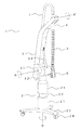
図1は、本発明の実施例1に係るプローブ支持装置の外観図である。プローブ支持装置1は、基台部2、アーム部3、非変形部4、変形部5を主たる構成とする。非変形部4と変形部5を合わせてプローブ支持部とも呼ぶ。
<Example 1>
FIG. 1 is an external view of a probe support device according to
基台部2は、プローブ支持装置の全体を支える脚柱であり、柱状部21と脚羽根22で構成される。柱状部21の高さは、伸縮部23の伸縮によって可変である。そのため、診察台の高さ等に応じて、プローブ支持装置の高さを変更することが可能である。脚羽根22は、基台部2の下部に枝分かれ状に構成され、プローブ支持装置の転倒を防止する構造となっている。また、各脚羽根22の先端下部にはキャスター24を有し、プローブ支持装置を移動することができる。基台部2の下部の構造は、脚羽根22の代わりに、円盤状、矩形状の構造とすることも可能である。
The
アーム部3は、基台部2の上端に俯仰可能および水平方向に回動可能に接続される。俯仰とは、アーム部3が倒れる、または起き上がる方向の動きであり、俯仰回動部31の軸Aを中心とした回動により実現する。水平方向の回動は、水平回動部32の軸Bを中心とした回動により実現する。アーム部3は、可倒方向に先端が突出するように屈曲しており、アーム部3が倒れた際に下部の空間を確保することができる。これによって、アーム部3が倒れた状態においても、ユーザーが手技をしやすい、被検者が圧迫感を感じない、等の効果が生じる。
The
アーム部3の屈曲については、図1のような“く”の字状に限定されず、円弧状とすることも可能である。また、アーム部3の俯仰については、アーム部3の自重で倒れないように、保持手段33によって可倒方向へのアーム部3の傾斜角度が保たれるように制御される。これによって、アーム部3が自重で倒れ、超音波プローブ等が被検者に衝突するのを防止することができる。また、倒れた状態のアーム部3をより小さな力で持ち上げることが可能であるため、ユーザーの負担を軽減することができる。本実施例では、保持手段33をガススプリングで構成しているが、ばね、カウンターウェイト、あるいはこれらの組み合わせとすることも可能である。
The bending of the
非変形部4は、円筒状の構造体であり、アーム部3の上端近傍に、アーム部3が俯仰する際の回転軸(軸A)と平行な軸A’に対して回動可能に接続される。非変形部4はプローブ支持部の一部であり、アーム部の基台部と接続する部分と逆側の先端に接続されている。
The
図2は、本発明の実施例1に係るプローブ支持装置のアーム部3と非変形部4の接続部の概略図である。図2では、アーム部3の外枠を取り去り、内部のフレーム34と軸受35がむき出しになった状態を示している。
FIG. 2 is a schematic diagram of a connection portion between the
図2(a)に示すように、アーム部3の内部に構成されるフレーム34の上端に軸受35が接続され、該軸受35の二枚の平行な金属板によって軸37が挟み込まれるように固定される。支持体36は、軸37に対して回動自在となるように接続され、該支持体36を貫通するように非変形部4が固定される。軸37を回転軸とした支持体36の回動は、非変形部4および変形部5の自重によって非変形部4および変形部5が鉛直方向に垂下するように調整されている。これにより、アーム部3と非変形部4の接続部が、被検部位の直上に位置するようにプローブ支持装置1およびアーム部3を移動させることができ、ユーザーの操作性が向上する。
As shown in FIG. 2A, a
アーム部3と非変形部4の接続部については、アーム部3が俯仰する際の回転軸(軸A)と平行な軸A’に対して回動可能に接続されていれば良い。例えば、図2(b)、図2(c)に示すように支持体38と一体に構成された突起39を軸受35で挟み込んだ構成とすることも可能である。図2(c)は支持体38の上部から見た図(上面図)である。
About the connection part of the
変形部5は、力を加えられることによって可逆的に屈曲することが可能な構造体であり、非変形部4の下端に接続される。本実施例においては、変形部5をプラスチック製のケーブルガイドによって構成している。ケーブルガイドは電子機器の電源ケーブルやコントロール用ケーブルを内部に収納し、ケーブル可動時の断線等を防止することが可能な外殻部材である。該ケーブルガイドを適用した変形部5は、外からの力を加えない場合は鉛直方向に垂下した状態であるが、超音波プローブ6を水平方向に移動させる際に加わる力によって、屈曲する。また、変形部5は、超音波プローブ6を上方に持ち上げる際に加えられる力を非変形部4に伝達することが可能であり、アーム部3を上方に持ち上げることができる。
The
変形部5を構成する部材は、可逆的に屈曲することが可能で、上部に力を伝達する程度の剛性を有していればケーブルガイドに限定されない。ステンレス等の金属部材で構成されるフレキシブルアーム、ゴムホース等の弾性体を用いることも可能である。
The member constituting the
超音波プローブ6は、検査用の超音波を照射・検出する素子を含んで構成されるものであり、検査目的・部位に応じて様々な種類のものが提供されている。超音波プローブ6は、本発明のプローブ支持装置と接続される別部材としても良いし、一体に構成されても良い。前者の場合、目的に応じてプローブを交換することができる。
The
図3は、本発明の実施例1に係るプローブ支持装置の使用状態図である。本発明のプローブ支持装置1は、超音波検査時に超音波装置8と併設して使用される。超音波プローブ6は変形部5の下端に接続され、ケーブル7は変形部5および非変形部4の内部を通して超音波装置8本体に接続される。すなわち超音波プローブ6は、変形部5の非変形部4と接続する部分とは逆側の先端に接続されている。ユーザー9は、アーム部3から垂下する超音波プローブ6が診察台11上の被検者10の被検部位の略直上に位置するように、アーム部3の俯仰、水平方向の位置を調整する。
FIG. 3 is a diagram illustrating a usage state of the probe support device according to the first embodiment of the invention. The
その後、ユーザー9は、把持した超音波プローブ6を被検部位に押し当てて、超音波検査を実行する。測定点を移動する際は、超音波プローブ6をそのまま新たな測定点に向けて移動させることにより、変形部5、非変形部4を介して軸37に張力が伝わるため、アーム部3を俯仰、水平方向に回転させることができる。検査が終わると、ユーザー9が把持した超音波プローブ6を持ち上げることにより、変形部5および非変形部4を介して軸37に力が伝わり、アーム部3を動かすことができる。
After that, the
以上に説明したように、本発明の実施例1に係るプローブ支持装置によれば、ユーザーが超音波プローブを動かすことにより、力がアーム部に伝達して、モーター等の駆動装置を用いることなくアーム部3の俯仰、水平方向の回転を制御することができる。そのため、プローブが被検部位の略直上に位置するように支持することが可能となる。
その結果、コストを抑制しつつ、超音波プローブの使用状態に応じて超音波プローブを支持することができ、ユーザーの負担を軽減することが可能となる。
As described above, according to the probe support device according to the first embodiment of the present invention, when the user moves the ultrasonic probe, the force is transmitted to the arm portion without using a driving device such as a motor. The elevation and horizontal rotation of the
As a result, it is possible to support the ultrasonic probe according to the usage state of the ultrasonic probe while suppressing the cost, and to reduce the burden on the user.
なお、特許文献1、2に開示されるプローブ支持装置と異なり、ケーブル7が非変形部4の内部を通って垂下するため、アーム部3の上端近傍で大きく折れ曲がることがなく、ケーブルの断線等の破損を軽減することができる。
Unlike the probe support devices disclosed in
<実施例2>
実施例2では、プローブ支持部(特に変形部)の剛性により、ユーザーが所定の値以上の距離を持ち上げることによって前記アーム部が持ち上がるプローブ支持装置の例について説明する。
<Example 2>
In the second embodiment, an example of a probe support device will be described in which the arm portion is lifted by the user lifting a distance equal to or greater than a predetermined value due to the rigidity of the probe support portion (particularly, the deformation portion).
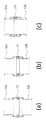
図4は、本発明の実施例2に係るプローブ支持装置の変形部を構成する部材の概略図である。図4(a)は部材51の側面図、図4(b)は部材51の断面図、図4(c)は部材52の側面図、図4(d)は部材52の断面図である。
FIG. 4 is a schematic view of members constituting the deforming portion of the probe support device according to the second embodiment of the present invention. 4A is a side view of the
本実施例では、部材51と部材52を交互に連結して変形部5を構成する。部材51は内壁に凹凸形状を有する円筒状の構造体であり、部材52は外壁に凹凸形状を有する円筒状の構造体である。部材51の直径が部材52の直径よりも僅かに大きく、部材51内壁の凹凸形状と部材52外壁の凹凸形状が噛み合うように設計されているため、部材51と部材52を連結することができる。
In this embodiment, the
図5は、本発明の実施例2に係るプローブ支持装置の変形部の伸縮の様子を示す模式図である。図5(a)は部材51と部材52の連結部が伸びた状態、図5(b)は途中段階、図5(c)は縮んだ状態を示す。
FIG. 5 is a schematic diagram illustrating a state of expansion and contraction of the deformable portion of the probe support device according to the second embodiment of the present invention. 5A shows a state in which the connecting portion between the
図5(а)は、自重により変形部5が垂下する、あるいは、ユーザーが超音波プローブを鉛直下方に引っ張る等、変形部5に対して鉛直下方への力が作用する際の部材51と部材52の連結部の状態である。この状態では、部材51内壁上端の凸部が部材52a外壁下端の凸部に引っかかり、部材52b外壁上端の凸部が部材51内壁下端の凸部に引っかかることにより、部材51と部材52の連結部は伸びた状態となっている。この状態からユーザーが超音波プローブ6を更に鉛直下方に引っ張る等、変形部5に対して更なる鉛直下方への力が作用すると、その力が部材51と部材52の各凸部同士の引っかかり部分を通じて軸37に作用するため、アーム部3は下方に倒れることとなる。
FIG. 5A shows
図5(b)は、図5(a)の状態からユーザーが超音波プローブ6を鉛直上方に僅かに持ち上げた際の部材51と部材52の連結部の状態である。この状態は、下方から鉛直上方への力を受けた変形部最下端の部材52bが上昇し、該部材52b外壁上端の凸部が、上方に連結する部材51内壁中部の凸部に突き当たった状態である。この状態からユーザーが超音波プローブ6を更に鉛直上方に持ち上げると、最下端の部材52bと上方に連結する部材51が接したまま上昇し、該部材51内壁中部の凸部が上方に連結する部材52a外壁下端の凸部に突き当たるまで上昇する。その結果、図5(c)のように部材51と部材52の連結部が縮んだ状態に至る。
FIG. 5B shows a state of the connecting portion between the
ここで、図5の部材52aの上にも、部材51、部材52、…、といったように、変形部が連続しているものと考える。その場合、図5(c)の状態において、更に下方から鉛直上方への力が作用すると、部材51aより上にある連結部も、下方のものから順次、図5(c)の状態へと変化する。部材51と部材52の連結部が全て図5(c)のようになった状態から更に鉛直上方への力が作用すると、その力が部材51と部材52の各凸部同士の突き当たり部分を通じて軸37に作用するため、アーム部3は上方に持ちあがることとなる。
Here, it is considered that the deformed portion is continuous on the
以上に説明したように、本発明の実施例2に係るプローブ支持装置によれば、超音波プローブを持ち上げても、全ての部材51と部材52の連結部が縮んだ状態となる所定の距離までは、力がアーム部に伝達されない。一方、全ての部材51と部材52の連結部が縮んだ状態となる所定の距離以上に超音波プローブを持ち上げると、力がアーム部に伝達され、アーム部が持ち上がることとなる。このことにより、ユーザーが被検部位近傍の検査のために超音波プロ―ブを所定の距離内で持ち上げても、アーム部に力が伝達しないため、ユーザーは超音波プローブを軽微な力で移動させることができる。一方、ユーザーが被検部位を変更するために超音波プローブを所定の距離以上持ち上げた際には、アーム部に力が伝達する。そのため、本実施例に係るプローブ支持装置は実施例1と同様に、モーター等の駆動装置を用いずに、超音波プローブが被検部位の略直上に位置するように支持することができる。
As described above, according to the probe support device according to the second embodiment of the present invention, even when the ultrasonic probe is lifted, the connection portions of all the
なお、このように変形部5により吸収される所定の値以下の力は、持ち上げ方向のみに限られず、水平方向、斜め方向であっても良い。すなわち変形部5は、所定の値より小さい力が加えられてもその力を変形により吸収し、所定の値以上の力が加えられて初めて力をアーム部に伝達するような材料、構造としても良い。変形部5をそのように構成すれば、ユーザーの動作に対してアーム部が追従しすぎることによる煩雑さを抑制できる。
In addition, the force below the predetermined value absorbed by the
<実施例3>
実施例3では、アーム部の俯仰に応じて、前記基台部が伸縮する本発明のプローブ支持装置の例について説明する。
<Example 3>
In Example 3, an example of the probe support device of the present invention in which the base part expands and contracts according to the elevation of the arm part will be described.
図6は、本発明の実施例1に係るプローブ支持装置の動作の様子を示す図である。図6(a)はアーム部3が最も起き上がった状態、図6(b)は途中段階、図6(c)はアーム部3が最も倒れた状態である。
FIG. 6 is a diagram illustrating an operation state of the probe support device according to the first embodiment of the present invention. 6A shows a state in which the
図6(a)において、ユーザーがアーム部3を下方に押し下げるか、非変形部4、変形部5、超音波プローブ6のいずれかを下方から引っ張る等すると、アーム部3に対して下方への力が作用する。その結果、アーム部3の俯仰回動部31が軸Aを回転軸として回動することにより、図6(b)の状態に至る。
In FIG. 6A, when the user pushes down the
図6(b)においては、保持手段33の作用により、アーム部3が自重で倒れることがなく、ユーザーが手を離しても高さが保持される。図6(b)の状態からさらに下方に力を作用させると、図6(c)のように最も倒れた状態に至る。反対に、図6(c)の状態から、上方に力を作用させることにより、図6(b)→図6(a)のように、アーム部3が起き上がる。
In FIG. 6B, the
ここで、アーム部3が図6(b)→図6(c)のように倒れていくと、そのままでは、変形部5、超音波プローブ6が被検者や診察台等に衝突してしまうおそれがある。そこで、図6(d)のように、アーム部3が倒れてくるのに伴い、伸縮部23を伸長する。このことにより、被検者や診察台等への衝突を回避することが可能となる。また、アーム部3が起き上がると、そのままでは超音波プローブ6の位置が高くなり、ユーザーの手が届かなくなるおそれがある。そこで、アーム部3が起き上がるのに伴い、伸縮部23を縮めることにより、超音波プローブ6の位置が高くなりすぎることを回避できる。アーム部3の俯仰に伴う伸縮部23の伸縮は、フットペダル等の操作部材によってユーザーに操作させる構成としても良いし、アーム部3の俯仰に連動して伸縮する機構を備える構成としても良い。
Here, when the
また、図6(a)の状態から手前方向に力を作用させると、水平回動部32の軸Bを回転軸として手前方向への回動により、図6(e)の状態に至る。 Further, when a force is applied in the forward direction from the state of FIG. 6A, the state of FIG. 6E is reached by rotating in the forward direction about the axis B of the horizontal rotation portion 32 as a rotation axis.
以上に説明したように、本発明の実施例3に係るプローブ支持装置によれば、ユーザーが超音波プローブを被検者や診察台等に衝突させる恐れなくアーム部を俯仰させて、被検部位の略直上にプローブを位置させるプローブ支持装置を提供することが可能となる。 As described above, according to the probe support device according to the third embodiment of the present invention, the user can raise the arm portion without fear of causing the ultrasonic probe to collide with the examinee or the examination table. It is possible to provide a probe support device that positions a probe substantially immediately above the position.
<実施例4>
実施例4では、所定の角度以上の折れ曲がりを規制する構造である本発明の実施例4に係るプローブ支持装置について説明する。
<Example 4>
In the fourth embodiment, a probe support device according to a fourth embodiment of the present invention, which is a structure that restricts bending over a predetermined angle, will be described.
本発明のプローブ支持装置の変形部5は、たとえば以下のような構造とすることで、所定の角度以上に折り曲がらないように規制することが可能である。なお本実施例では、実施例2と同様に、部材51と部材52を交互に連結して変形部5を構成するものとする。
The
図7は本発明の実施例4に係るプローブ支持装置の変形部が屈曲する様子を示す模式図である。図7(a)は部材51と部材52の連結部が真っ直ぐ伸びた状態、図7(b)は矢印の方向に力を受けて屈曲した状態を示す。
FIG. 7 is a schematic diagram showing a state where the deformed portion of the probe support device according to the fourth embodiment of the present invention is bent. FIG. 7A shows a state in which the connecting portion between the
図7(а)の状態から、ユーザーが超音波プローブを傾ける等して、鉛直方向に対して横方向や斜め方向の力が変形部5に作用すると、部材51と部材52の連結部で各部材同
士が傾き、図7(b)の屈曲した状態に至る。図7(b)では、部材51内壁の凸部と部材52外壁の凸部が突き当たるため、それ以上屈曲することができない状態である。この屈曲を規制する角度については、部材51および部材52の直径や凸部の間隔等を変更することで調整することが可能である。
When the user inclines the ultrasonic probe from the state of FIG. 7 (a) and a force in the lateral direction or the oblique direction acts on the
以上に説明したように、本実施例のプローブ支持装置によれば、鉛直方向に対して斜め方向の力が作用した際に、所定の角度以上の変形部の屈曲を規制することが可能となる。このことにより、ケーブルの過度な折り曲げによる破損を防止しながら、被検部位の略直上にプローブを位置させるプローブ支持装置を提供することが可能となる。 As described above, according to the probe support device of the present embodiment, when a force in an oblique direction is applied to the vertical direction, it is possible to regulate the bending of the deformed portion having a predetermined angle or more. . As a result, it is possible to provide a probe support device that positions the probe substantially directly above the region to be examined while preventing breakage due to excessive bending of the cable.
<実施例5>
実施例5では、光音響装置に用いられる光音響プローブに本発明のプローブ支持装置を適用した例について説明する。ハンドヘルド型の光音響プローブを用いる場合、プローブにおいて、レーザーなどの光源から導かれたパルス光を被検体に照射する機構と、被検体内の吸収体から発生した光音響波(典型的には超音波)を検出する機構が必要となる。さらに、光音響波を検出する機構が超音波を送信する機構を兼ねる、あるいは超音波を送信する機構を別に設けることにより、超音波プローブに光音響プローブを兼ねさせることもできる。
<Example 5>
In Example 5, an example in which the probe support device of the present invention is applied to a photoacoustic probe used in a photoacoustic device will be described. When a handheld photoacoustic probe is used, the probe irradiates the subject with pulsed light guided from a light source such as a laser, and a photoacoustic wave (typically supersonic wave generated from an absorber in the subject). A mechanism for detecting sound waves is required. Furthermore, the mechanism for detecting a photoacoustic wave also serves as a mechanism for transmitting ultrasonic waves, or by providing a mechanism for transmitting ultrasonic waves separately, the ultrasonic probe can also serve as a photoacoustic probe.
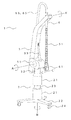
図8は、本発明の実施例5に係るプローブ支持装置の外観図である。実施例1と同一の符号が付与されたものについては同様の内容であるため、説明を省略する。光音響プローブ61は、光音響検査を行うためのパルス光を照射するユニット(光照射ユニット)および超音波を照射・検出するユニット(超音波ユニット)で構成される。
FIG. 8 is an external view of a probe support apparatus according to
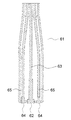
図9はCC’を通る平面で光音響プローブ61を切断した際の断面図である。超音波ユニット62は、超音波を照射・検出する素子を含み、実施例1で説明した超音波プローブに用いられるものと同様の構成である。ケーブル63は、超音波ユニットを光音響装置に接続するケーブルである。光照射ユニット64は、光音響検査を行うためのパルス光を照射するユニットであり、レーザー光源で出射されたパルス光を被検部位に導光するための光学プリズム等で構成される。光ファイバー65は、レーザー光源で出射されたパルス光を光照射ユニット64まで導光する光学部材である。光照射ユニット64から照射されたパルス光によって生体組織から発生する音響波を超音波ユニット62で検出することにより、光音響検査が実現される。
FIG. 9 is a cross-sectional view of the
変形部51は、外からの力によって可逆的に屈曲することが可能な構造体であり、実施例4で説明したものと同様である。
光音響プローブ61は、変形部51の下端に接続され、ケーブル63および光ファイバー65は、変形部51および非変形部4の内部を通して光音響装置本体に接続される。
The
The
上述したように光音響プローブは光照射ユニットおよび超音波ユニットから構成されるため、この種の検査装置に一般的に用いられるプローブよりも重量が大きくなる。また、プローブ支持部は電気信号を伝達するケーブルと光ファイバーとより構成されるため、一般的なプローブ支持部よりも高い剛性を有する。さらに、光ファイバーは、レーザー光源で出射されたパルス光を導光する光学部材であるから、過度の折れ曲がりによりその性能が毀損することとなる。以上より、本発明の実施例5に係るプローブ支持装置は、光音響検査に使用するプローブ支持装置として、被検部位の略直上にプローブを位置させるプローブ支持装置に特に好適なものである。 As described above, since the photoacoustic probe is composed of a light irradiation unit and an ultrasonic unit, it is heavier than a probe generally used in this type of inspection apparatus. Further, since the probe support portion is composed of a cable for transmitting an electrical signal and an optical fiber, it has higher rigidity than a general probe support portion. Furthermore, since the optical fiber is an optical member that guides the pulsed light emitted from the laser light source, its performance is impaired due to excessive bending. As described above, the probe support device according to the fifth embodiment of the present invention is particularly suitable as a probe support device used for photoacoustic examination, in a probe support device that positions a probe substantially directly above a region to be examined.
とりわけ変形部51として実施例4と同様の構成を用いれば、過度の屈曲を防止しつつ、ユーザーによる超音波プローブ操作への追従性を維持できるため、折り曲げからの保護
の必要性が高い光ファイバーを用いる光音響プローブを良好に使用できる。
さらに光音響プローブは重量が大きいことから、ユーザーの負担を軽減する効果が大きい。
In particular, if the same configuration as that of the fourth embodiment is used as the deforming
Furthermore, since the photoacoustic probe is heavy, the effect of reducing the burden on the user is great.
しかしながら、本発明の構成は、検査プローブを有する検査装置全般に適用可能である。 However, the configuration of the present invention is applicable to all inspection apparatuses having an inspection probe.
1:プローブ支持装置,2:基台部,3:アーム部,31:俯仰回動部,32:水平回動部,4:非変形部,5:変形部,6:超音波プローブ,8:超音波装置 DESCRIPTION OF SYMBOLS 1: Probe support apparatus, 2: Base part, 3: Arm part, 31: Elevation rotation part, 32: Horizontal rotation part, 4: Non-deformation part, 5: Deformation part, 6: Ultrasonic probe, 8: Ultrasonic device
Claims (13)
前記基台部の上端に俯仰可能かつ水平方向に回動可能に接続されたアーム部と、
前記アーム部が前記基台部と接続する部分に対して前記アーム部の逆側に接続されたプローブ支持部と、
を有するプローブ支持装置であって、
前記プローブ支持部は変形部と非変形部で構成され、前記非変形部は前記アーム部が俯仰する際の回転軸と平行な軸に対して回動可能に前記アーム部に接続される
ことを特徴とするプローブ支持装置。 A base,
An arm part connected to the upper end of the base part so as to be able to be lifted and rotated in a horizontal direction;
A probe support portion connected to the opposite side of the arm portion with respect to a portion where the arm portion is connected to the base portion;
A probe support device comprising:
The probe support portion is composed of a deformable portion and a non-deformable portion, and the non-deformable portion is connected to the arm portion so as to be rotatable with respect to an axis parallel to a rotation axis when the arm portion is lifted. A probe support device.
ことを特徴とする請求項1に記載のプローブ支持装置。The probe support device according to claim 1.
ことを特徴とする請求項1に記載のプローブ支持装置。 Probe support device according to claim 1, wherein the deformable portion is a probe on the opposite side of the flexible portion to the portion to be connected to the non-deformable portion is connected.
ことを特徴とする請求項3に記載のプローブ支持装置。The probe support device according to claim 3.
ことを特徴とする請求項3または4に記載のプローブ支持装置。 5. The probe support according to claim 3 , wherein when the user lifts the probe by a distance equal to or greater than a predetermined value, the arm portion is lifted in accordance with the rise of the probe due to the rigidity of the probe support portion. apparatus.
ことを特徴とする請求項1ないし6のいずれか1項に記載のプローブ支持装置。 The probe supporting portion, the probe support device according to any one of claims 1 to 6, characterized in that for transmitting the force to the arm portion with a predetermined value or more force is applied.
ことを特徴とする請求項1ないし7のいずれか1項に記載のプローブ支持装置。 The probe support device according to any one of claims 1 to 7 , wherein the base portion expands and contracts according to the elevation of the arm portion.
ことを特徴とする請求項1ないし8のいずれか1項に記載のプローブ支持装置。 The flexible portion, the probe support device according to any one of claims 1 to 8, characterized in that a structure for regulating the bending of a predetermined angle or more.
前記プローブ支持装置のプローブ支持部に接続され、被検体に超音波を送信するとともに、前記被検体から反射した超音波を受信する超音波プローブと、
前記受信した超音波に基づき前記被検体の情報を取得する情報処理装置と、
を有することを特徴とする超音波装置。 The probe support device according to any one of claims 1 to 9 ,
An ultrasonic probe connected to the probe support part of the probe support device, for transmitting ultrasonic waves to the subject, and receiving ultrasonic waves reflected from the subject;
An information processing apparatus for acquiring information on the subject based on the received ultrasound;
An ultrasonic device comprising:
前記ケーブルは、前記情報処理装置から前記超音波プローブに向かって、前記アーム部、前記非変形部、前記変形部の順に、前記アーム部、前記非変形部、前記変形部に沿って延在する The cable extends from the information processing device toward the ultrasonic probe in the order of the arm portion, the non-deformable portion, and the deformable portion along the arm portion, the non-deformable portion, and the deformable portion.
ことを特徴とする請求項10に記載の超音波装置。The ultrasonic apparatus according to claim 10.
前記プローブ支持装置のプローブ支持部に接続され、光を照射された被検体から発生する光音響波を受信する光音響プローブと、
前記受信した光音響波に基づき前記被検体の情報を取得する情報処理装置と、
を有することを特徴とする光音響装置。 The probe support device according to any one of claims 1 to 9 ,
A photoacoustic probe connected to a probe support part of the probe support device and receiving a photoacoustic wave generated from a subject irradiated with light; and
An information processing apparatus for acquiring information on the subject based on the received photoacoustic wave;
A photoacoustic apparatus comprising:
前記光を前記光源から前記光音響プローブに導く光ファイバーと、 An optical fiber that guides the light from the light source to the photoacoustic probe;
をさらに有し、Further comprising
前記光ファイバーは、前記光源から前記光音響プローブに向かって、前記アーム部、前記非変形部、前記変形部の順に、前記アーム部、前記非変形部、前記変形部に沿って延在する The optical fiber extends from the light source toward the photoacoustic probe in the order of the arm portion, the non-deformable portion, and the deformable portion along the arm portion, the non-deformed portion, and the deformable portion.
ことを特徴とする請求項12に記載の光音響装置。The photoacoustic apparatus according to claim 12.
Priority Applications (4)
| Application Number | Priority Date | Filing Date | Title |
|---|---|---|---|
| JP2012237939A JP6000803B2 (en) | 2012-10-29 | 2012-10-29 | Probe support device |
| US14/433,731 US9615795B2 (en) | 2012-10-29 | 2013-10-08 | Probe support apparatus |
| PCT/JP2013/005972 WO2014068853A1 (en) | 2012-10-29 | 2013-10-08 | Probe support apparatus |
| US15/449,106 US20170172506A1 (en) | 2012-10-29 | 2017-03-03 | Probe support apparatus |
Applications Claiming Priority (1)
| Application Number | Priority Date | Filing Date | Title |
|---|---|---|---|
| JP2012237939A JP6000803B2 (en) | 2012-10-29 | 2012-10-29 | Probe support device |
Publications (3)
| Publication Number | Publication Date |
|---|---|
| JP2014087399A JP2014087399A (en) | 2014-05-15 |
| JP2014087399A5 JP2014087399A5 (en) | 2015-11-12 |
| JP6000803B2 true JP6000803B2 (en) | 2016-10-05 |
Family
ID=49486622
Family Applications (1)
| Application Number | Title | Priority Date | Filing Date |
|---|---|---|---|
| JP2012237939A Active JP6000803B2 (en) | 2012-10-29 | 2012-10-29 | Probe support device |
Country Status (3)
| Country | Link |
|---|---|
| US (2) | US9615795B2 (en) |
| JP (1) | JP6000803B2 (en) |
| WO (1) | WO2014068853A1 (en) |
Families Citing this family (4)
| Publication number | Priority date | Publication date | Assignee | Title |
|---|---|---|---|---|
| JP6570341B2 (en) | 2015-06-30 | 2019-09-04 | キヤノン株式会社 | Radiation CT apparatus and control method thereof |
| JP6299738B2 (en) * | 2015-12-24 | 2018-03-28 | トヨタ自動車株式会社 | Non-contact power transmission device and power transmission system |
| KR20190102598A (en) * | 2018-02-26 | 2019-09-04 | 삼성메디슨 주식회사 | Ultrasound diagnosis apparatus and cable supportingapparatus for the same |
| US20220313211A1 (en) * | 2021-04-05 | 2022-10-06 | Mahmoud I. Eltorai | Ultrasound support device |
Family Cites Families (13)
| Publication number | Priority date | Publication date | Assignee | Title |
|---|---|---|---|---|
| JP2768517B2 (en) * | 1989-12-19 | 1998-06-25 | アロカ株式会社 | Cable hanger for ultrasonic diagnostic equipment |
| JPH0475646A (en) * | 1990-07-17 | 1992-03-10 | Toshiba Corp | Ultrasonic diagnostic device |
| JPH04210051A (en) * | 1990-12-05 | 1992-07-31 | Toshiba Corp | Cable guide apparatus |
| JPH0584242A (en) * | 1991-09-30 | 1993-04-06 | Fujitsu Ltd | Ultrasonic diagnostic device |
| JPH0670927A (en) * | 1992-08-27 | 1994-03-15 | Toshiba Corp | Ultrasonic diagnostic device |
| IL107523A (en) * | 1993-11-07 | 2000-01-31 | Ultraguide Ltd | Articulated needle guide for ultrasound imaging and method of using same |
| JPH07178097A (en) * | 1993-12-22 | 1995-07-18 | Toshiba Corp | Ultrasonic diagnostic system |
| JP2005312577A (en) * | 2004-04-28 | 2005-11-10 | Ge Medical Systems Global Technology Co Llc | Ultrasonic diagnostic apparatus |
| US7806862B2 (en) | 2008-05-02 | 2010-10-05 | Molnar James M | Regional anesthesia system and cart |
| US9528966B2 (en) | 2008-10-23 | 2016-12-27 | Washington University | Reflection-mode photoacoustic tomography using a flexibly-supported cantilever beam |
| US20110213247A1 (en) | 2010-01-08 | 2011-09-01 | Hexagon Metrology, Inc. | Articulated arm with imaging device |
| JP6014329B2 (en) | 2012-01-17 | 2016-10-25 | キヤノン株式会社 | X-ray equipment |
| JP5917162B2 (en) | 2012-01-19 | 2016-05-11 | キヤノン株式会社 | X-ray equipment |
-
2012
- 2012-10-29 JP JP2012237939A patent/JP6000803B2/en active Active
-
2013
- 2013-10-08 WO PCT/JP2013/005972 patent/WO2014068853A1/en active Application Filing
- 2013-10-08 US US14/433,731 patent/US9615795B2/en active Active
-
2017
- 2017-03-03 US US15/449,106 patent/US20170172506A1/en not_active Abandoned
Also Published As
| Publication number | Publication date |
|---|---|
| US9615795B2 (en) | 2017-04-11 |
| JP2014087399A (en) | 2014-05-15 |
| WO2014068853A1 (en) | 2014-05-08 |
| US20150272502A1 (en) | 2015-10-01 |
| US20170172506A1 (en) | 2017-06-22 |
Similar Documents
| Publication | Publication Date | Title |
|---|---|---|
| JP6000803B2 (en) | Probe support device | |
| JP6486068B2 (en) | Test site information acquisition device | |
| US10653377B2 (en) | Breast computed tomography system comprising a gripper | |
| JP6274819B2 (en) | Test site information acquisition device | |
| EP3188646B1 (en) | Object information acquiring apparatus | |
| JP6648919B2 (en) | Subject information acquisition device | |
| US20180008148A1 (en) | Subject information acquisition apparatus | |
| US11058357B2 (en) | Acoustic wave apparatus and control method thereof | |
| JP2016101369A (en) | Photoacoustic device and control method of photoacoustic device | |
| JP2017196026A (en) | Subject information acquisition device | |
| WO2016051749A1 (en) | Object information acquiring apparatus | |
| US20150105649A1 (en) | Subject information acquisition apparatus | |
| US10288719B2 (en) | Object information acquiring apparatus and information processing apparatus | |
| JP2016002373A (en) | Object information acquisition apparatus | |
| JP2013220171A (en) | Imaging probe | |
| US20190320907A1 (en) | Photoacoustic apparatus and object information acquiring method | |
| JP2017077411A (en) | Analyte information acquisition device | |
| JP5250473B2 (en) | Medical treatment equipment | |
| JP6497896B2 (en) | Information acquisition device | |
| JP6444126B2 (en) | Photoacoustic apparatus and photoacoustic wave measuring method | |
| JP2017046763A (en) | Photoacoustic wave measurement device | |
| US11526982B2 (en) | Image processing device, image processing method, and program | |
| JP2018079020A (en) | Acoustic wave reception device and float | |
| JP6742700B2 (en) | Subject support device and subject information acquisition device | |
| JP2015029684A (en) | Subject site information acquisition apparatus |
Legal Events
| Date | Code | Title | Description |
|---|---|---|---|
| A521 | Request for written amendment filed |
Free format text: JAPANESE INTERMEDIATE CODE: A523 Effective date: 20150918 |
|
| A621 | Written request for application examination |
Free format text: JAPANESE INTERMEDIATE CODE: A621 Effective date: 20150918 |
|
| TRDD | Decision of grant or rejection written | ||
| A01 | Written decision to grant a patent or to grant a registration (utility model) |
Free format text: JAPANESE INTERMEDIATE CODE: A01 Effective date: 20160802 |
|
| A61 | First payment of annual fees (during grant procedure) |
Free format text: JAPANESE INTERMEDIATE CODE: A61 Effective date: 20160831 |
|
| R151 | Written notification of patent or utility model registration |
Ref document number: 6000803 Country of ref document: JP Free format text: JAPANESE INTERMEDIATE CODE: R151 |