JP5987809B2 - 回転式ポンプ装置 - Google Patents
回転式ポンプ装置 Download PDFInfo
- Publication number
- JP5987809B2 JP5987809B2 JP2013212112A JP2013212112A JP5987809B2 JP 5987809 B2 JP5987809 B2 JP 5987809B2 JP 2013212112 A JP2013212112 A JP 2013212112A JP 2013212112 A JP2013212112 A JP 2013212112A JP 5987809 B2 JP5987809 B2 JP 5987809B2
- Authority
- JP
- Japan
- Prior art keywords
- shaft
- seal member
- plate
- ring
- rotation
- Prior art date
- Legal status (The legal status is an assumption and is not a legal conclusion. Google has not performed a legal analysis and makes no representation as to the accuracy of the status listed.)
- Active
Links
Images


Classifications
-
- B—PERFORMING OPERATIONS; TRANSPORTING
- B60—VEHICLES IN GENERAL
- B60T—VEHICLE BRAKE CONTROL SYSTEMS OR PARTS THEREOF; BRAKE CONTROL SYSTEMS OR PARTS THEREOF, IN GENERAL; ARRANGEMENT OF BRAKING ELEMENTS ON VEHICLES IN GENERAL; PORTABLE DEVICES FOR PREVENTING UNWANTED MOVEMENT OF VEHICLES; VEHICLE MODIFICATIONS TO FACILITATE COOLING OF BRAKES
- B60T11/00—Transmitting braking action from initiating means to ultimate brake actuator without power assistance or drive or where such assistance or drive is irrelevant
- B60T11/10—Transmitting braking action from initiating means to ultimate brake actuator without power assistance or drive or where such assistance or drive is irrelevant transmitting by fluid means, e.g. hydraulic
- B60T11/16—Master control, e.g. master cylinders
- B60T11/22—Master control, e.g. master cylinders characterised by being integral with reservoir
-
- B—PERFORMING OPERATIONS; TRANSPORTING
- B60—VEHICLES IN GENERAL
- B60T—VEHICLE BRAKE CONTROL SYSTEMS OR PARTS THEREOF; BRAKE CONTROL SYSTEMS OR PARTS THEREOF, IN GENERAL; ARRANGEMENT OF BRAKING ELEMENTS ON VEHICLES IN GENERAL; PORTABLE DEVICES FOR PREVENTING UNWANTED MOVEMENT OF VEHICLES; VEHICLE MODIFICATIONS TO FACILITATE COOLING OF BRAKES
- B60T11/00—Transmitting braking action from initiating means to ultimate brake actuator without power assistance or drive or where such assistance or drive is irrelevant
- B60T11/10—Transmitting braking action from initiating means to ultimate brake actuator without power assistance or drive or where such assistance or drive is irrelevant transmitting by fluid means, e.g. hydraulic
- B60T11/16—Master control, e.g. master cylinders
- B60T11/224—Master control, e.g. master cylinders with pressure-varying means, e.g. with two stage operation provided by use of different piston diameters including continuous variation from one diameter to another
-
- B—PERFORMING OPERATIONS; TRANSPORTING
- B60—VEHICLES IN GENERAL
- B60T—VEHICLE BRAKE CONTROL SYSTEMS OR PARTS THEREOF; BRAKE CONTROL SYSTEMS OR PARTS THEREOF, IN GENERAL; ARRANGEMENT OF BRAKING ELEMENTS ON VEHICLES IN GENERAL; PORTABLE DEVICES FOR PREVENTING UNWANTED MOVEMENT OF VEHICLES; VEHICLE MODIFICATIONS TO FACILITATE COOLING OF BRAKES
- B60T11/00—Transmitting braking action from initiating means to ultimate brake actuator without power assistance or drive or where such assistance or drive is irrelevant
- B60T11/10—Transmitting braking action from initiating means to ultimate brake actuator without power assistance or drive or where such assistance or drive is irrelevant transmitting by fluid means, e.g. hydraulic
- B60T11/28—Valves specially adapted therefor
- B60T11/34—Pressure reducing or limiting valves
-
- B—PERFORMING OPERATIONS; TRANSPORTING
- B60—VEHICLES IN GENERAL
- B60T—VEHICLE BRAKE CONTROL SYSTEMS OR PARTS THEREOF; BRAKE CONTROL SYSTEMS OR PARTS THEREOF, IN GENERAL; ARRANGEMENT OF BRAKING ELEMENTS ON VEHICLES IN GENERAL; PORTABLE DEVICES FOR PREVENTING UNWANTED MOVEMENT OF VEHICLES; VEHICLE MODIFICATIONS TO FACILITATE COOLING OF BRAKES
- B60T8/00—Arrangements for adjusting wheel-braking force to meet varying vehicular or ground-surface conditions, e.g. limiting or varying distribution of braking force
- B60T8/32—Arrangements for adjusting wheel-braking force to meet varying vehicular or ground-surface conditions, e.g. limiting or varying distribution of braking force responsive to a speed condition, e.g. acceleration or deceleration
- B60T8/34—Arrangements for adjusting wheel-braking force to meet varying vehicular or ground-surface conditions, e.g. limiting or varying distribution of braking force responsive to a speed condition, e.g. acceleration or deceleration having a fluid pressure regulator responsive to a speed condition
- B60T8/40—Arrangements for adjusting wheel-braking force to meet varying vehicular or ground-surface conditions, e.g. limiting or varying distribution of braking force responsive to a speed condition, e.g. acceleration or deceleration having a fluid pressure regulator responsive to a speed condition comprising an additional fluid circuit including fluid pressurising means for modifying the pressure of the braking fluid, e.g. including wheel driven pumps for detecting a speed condition, or pumps which are controlled by means independent of the braking system
- B60T8/4031—Pump units characterised by their construction or mounting
-
- F—MECHANICAL ENGINEERING; LIGHTING; HEATING; WEAPONS; BLASTING
- F04—POSITIVE - DISPLACEMENT MACHINES FOR LIQUIDS; PUMPS FOR LIQUIDS OR ELASTIC FLUIDS
- F04C—ROTARY-PISTON, OR OSCILLATING-PISTON, POSITIVE-DISPLACEMENT MACHINES FOR LIQUIDS; ROTARY-PISTON, OR OSCILLATING-PISTON, POSITIVE-DISPLACEMENT PUMPS
- F04C11/00—Combinations of two or more machines or pumps, each being of rotary-piston or oscillating-piston type; Pumping installations
- F04C11/001—Combinations of two or more machines or pumps, each being of rotary-piston or oscillating-piston type; Pumping installations of similar working principle
-
- F—MECHANICAL ENGINEERING; LIGHTING; HEATING; WEAPONS; BLASTING
- F04—POSITIVE - DISPLACEMENT MACHINES FOR LIQUIDS; PUMPS FOR LIQUIDS OR ELASTIC FLUIDS
- F04C—ROTARY-PISTON, OR OSCILLATING-PISTON, POSITIVE-DISPLACEMENT MACHINES FOR LIQUIDS; ROTARY-PISTON, OR OSCILLATING-PISTON, POSITIVE-DISPLACEMENT PUMPS
- F04C15/00—Component parts, details or accessories of machines, pumps or pumping installations, not provided for in groups F04C2/00 - F04C14/00
- F04C15/0003—Sealing arrangements in rotary-piston machines or pumps
- F04C15/0034—Sealing arrangements in rotary-piston machines or pumps for other than the working fluid, i.e. the sealing arrangements are not between working chambers of the machine
- F04C15/0038—Shaft sealings specially adapted for rotary-piston machines or pumps
-
- F—MECHANICAL ENGINEERING; LIGHTING; HEATING; WEAPONS; BLASTING
- F04—POSITIVE - DISPLACEMENT MACHINES FOR LIQUIDS; PUMPS FOR LIQUIDS OR ELASTIC FLUIDS
- F04C—ROTARY-PISTON, OR OSCILLATING-PISTON, POSITIVE-DISPLACEMENT MACHINES FOR LIQUIDS; ROTARY-PISTON, OR OSCILLATING-PISTON, POSITIVE-DISPLACEMENT PUMPS
- F04C2/00—Rotary-piston machines or pumps
- F04C2/08—Rotary-piston machines or pumps of intermeshing-engagement type, i.e. with engagement of co-operating members similar to that of toothed gearing
- F04C2/10—Rotary-piston machines or pumps of intermeshing-engagement type, i.e. with engagement of co-operating members similar to that of toothed gearing of internal-axis type with the outer member having more teeth or tooth-equivalents, e.g. rollers, than the inner member
- F04C2/102—Rotary-piston machines or pumps of intermeshing-engagement type, i.e. with engagement of co-operating members similar to that of toothed gearing of internal-axis type with the outer member having more teeth or tooth-equivalents, e.g. rollers, than the inner member the two members rotating simultaneously around their respective axes
-
- B—PERFORMING OPERATIONS; TRANSPORTING
- B60—VEHICLES IN GENERAL
- B60T—VEHICLE BRAKE CONTROL SYSTEMS OR PARTS THEREOF; BRAKE CONTROL SYSTEMS OR PARTS THEREOF, IN GENERAL; ARRANGEMENT OF BRAKING ELEMENTS ON VEHICLES IN GENERAL; PORTABLE DEVICES FOR PREVENTING UNWANTED MOVEMENT OF VEHICLES; VEHICLE MODIFICATIONS TO FACILITATE COOLING OF BRAKES
- B60T8/00—Arrangements for adjusting wheel-braking force to meet varying vehicular or ground-surface conditions, e.g. limiting or varying distribution of braking force
- B60T8/32—Arrangements for adjusting wheel-braking force to meet varying vehicular or ground-surface conditions, e.g. limiting or varying distribution of braking force responsive to a speed condition, e.g. acceleration or deceleration
- B60T8/34—Arrangements for adjusting wheel-braking force to meet varying vehicular or ground-surface conditions, e.g. limiting or varying distribution of braking force responsive to a speed condition, e.g. acceleration or deceleration having a fluid pressure regulator responsive to a speed condition
- B60T8/48—Arrangements for adjusting wheel-braking force to meet varying vehicular or ground-surface conditions, e.g. limiting or varying distribution of braking force responsive to a speed condition, e.g. acceleration or deceleration having a fluid pressure regulator responsive to a speed condition connecting the brake actuator to an alternative or additional source of fluid pressure, e.g. traction control systems
- B60T8/4809—Traction control, stability control, using both the wheel brakes and other automatic braking systems
- B60T8/4827—Traction control, stability control, using both the wheel brakes and other automatic braking systems in hydraulic brake systems
- B60T8/4863—Traction control, stability control, using both the wheel brakes and other automatic braking systems in hydraulic brake systems closed systems
- B60T8/4872—Traction control, stability control, using both the wheel brakes and other automatic braking systems in hydraulic brake systems closed systems pump-back systems
Description
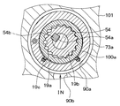
以下、本発明を図に示す実施形態について説明する。まず、図1を参照して、本発明の一実施形態にかかる回転式ポンプ装置を適用した車両用ブレーキ装置の基本構成について説明する。ここでは前輪駆動の4輪車において、右前輪−左後輪、左前輪−右後輪の各配管系統を備えるX配管の液圧回路を構成する車両に本発明による車両用ブレーキ装置を適用した例について説明するが、前後配管などの車両にも適用可能である。
本発明は上記した実施形態に限定されるものではなく、特許請求の範囲に記載した範囲内において適宜変更が可能である。
Claims (5)
- 回転式ポンプ(19、39)と、
前記回転式ポンプを駆動するシャフト(54)と、
前記シャフトが挿通される孔(72a〜72d)が形成され、該孔内において前記シャフトが相対回転させられるケース(71a〜71d)と、
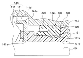
前記ケースの前記孔内に前記シャフトの軸方向に挿入されていると共に、前記孔の内周面と前記シャフトとの間において前記シャフトを囲んで配置され、リング(131)と、該リングの外周に嵌め込まれる弾性シール(132)とを有し、前記孔の内周面と前記シャフトとの間のシールを行うシール部材(130)と、
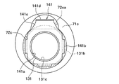
弾性力により、前記シール部材を前記ケースの前記孔内に形成された段付き部に押し付けることで前記シャフトの軸方向における前記シール部材の移動を規制する板バネ部(142)と、前記シャフトの回転に伴う供回りを規制する第1回り止め部(141c)と、前記リングに勘合することで前記シール部材が前記シャフトの回転に伴って供回りすることを規制する第2回り止め部(141b)とを有する押圧部材(140)と、を備えていることを特徴とする回転式ポンプ装置。 - 前記板バネ部は、前記シャフトが挿通される中心孔(142a)が形成された円盤状のバネ部材で構成されていると共に、該円盤状の部分の外周に部分的に突出させた支持部(142d)を備えた構成とされ、
前記ケースにおける前記孔の内壁面には、前記シャフトの周方向に沿って形成されると共に前記支持部が嵌め込まれる周溝(72cb、72cc)が形成されていることを特徴とする請求項1に記載の回転式ポンプ装置。 - 前記押圧部材に、前記板バネ部と前記シール部材との間に配置され、前記板バネ部の荷重を受け止めて前記リングの端面に加える板状部材で構成されたプレート(141)が備えられていると共に、
前記リングに、該リングにおける前記押圧部材側の端面の外周部に形成された勘合部(131b)が備えられており、
前記プレートの一部を前記シール部材側に折り曲げることで前記勘合部と勘合させられる前記第2回り止め部が構成されていることを特徴とする請求項1または2に記載の回転式ポンプ装置。 - 前記プレートの一部の径方向長さが該プレートの他の部位よりも長くされることで前記第1回り止め部が構成されていると共に、
前記ケースに、前記孔が前記第1回り止め部と対応する部位において部分的に径が拡大された切欠き溝(72ca)が形成されており、
前記第1回り止め部が前記切欠き溝内に配置されていると共に、該切欠き溝の内壁面と当接することで、前記シャフトの回転に伴う前記プレートの供回りを規制していることを特徴とする請求項3に記載の回転式ポンプ装置。 - ブレーキ操作部材(11)と、
前記ブレーキ操作部材の操作に基づいてブレーキ液圧を発生させるマスタシリンダ(13)と、
前記ブレーキ液圧に基づいて制動力を発生させるホイールシリンダ(14、15、34、35)と、
前記マスタシリンダと前記ホイールシリンダとを繋ぐ主管路(A、E)と、
前記主管路に備えられ、前記ホイールシリンダに掛かる前記ブレーキ液圧の増圧を制御する増圧制御弁(17、18、37、38)と、
前記主管路のうち前記増圧制御弁と前記ホイールシリンダとの間に接続された減圧管路(B、F)と、
前記減圧管路に備えられ、前記ホイールシリンダに掛かる前記ブレーキ液圧の減圧を制御する減圧制御弁(21、22、41、42)と、
前記減圧制御弁が連通状態にされたときに前記減圧管路を通じて前記主管路から排出されるブレーキ液を収容するリザーバ(20、40)と、
前記リザーバから前記主管路のうち前記マスタシリンダと前記増圧制御弁との間に接続された還流管路(C、G)と、を有し、
前記還流管路に請求項1ないし4のいずれか1つに記載の回転式ポンプ装置が備えられ、
前記ホイールシリンダに掛かるブレーキ液圧を増減することで車輪がロック傾向に至ることを抑制するアンチロックブレーキ制御を行い、前記回転式ポンプ装置にて前記リザーバ内のブレーキ液を前記主管路に返流するように構成されていることを特徴とする車両用ブレーキ装置。
Priority Applications (3)
| Application Number | Priority Date | Filing Date | Title |
|---|---|---|---|
| JP2013212112A JP5987809B2 (ja) | 2013-10-09 | 2013-10-09 | 回転式ポンプ装置 |
| US14/509,364 US9663084B2 (en) | 2013-10-09 | 2014-10-08 | Rotating pumping apparatus with seal mechanism |
| CN201410527796.6A CN104554224B (zh) | 2013-10-09 | 2014-10-09 | 旋转泵送装置和使用该旋转泵送装置的车辆用制动系统 |
Applications Claiming Priority (1)
| Application Number | Priority Date | Filing Date | Title |
|---|---|---|---|
| JP2013212112A JP5987809B2 (ja) | 2013-10-09 | 2013-10-09 | 回転式ポンプ装置 |
Publications (3)
| Publication Number | Publication Date |
|---|---|
| JP2015075177A JP2015075177A (ja) | 2015-04-20 |
| JP2015075177A5 JP2015075177A5 (ja) | 2015-09-17 |
| JP5987809B2 true JP5987809B2 (ja) | 2016-09-07 |
Family
ID=52775831
Family Applications (1)
| Application Number | Title | Priority Date | Filing Date |
|---|---|---|---|
| JP2013212112A Active JP5987809B2 (ja) | 2013-10-09 | 2013-10-09 | 回転式ポンプ装置 |
Country Status (3)
| Country | Link |
|---|---|
| US (1) | US9663084B2 (ja) |
| JP (1) | JP5987809B2 (ja) |
| CN (1) | CN104554224B (ja) |
Families Citing this family (6)
| Publication number | Priority date | Publication date | Assignee | Title |
|---|---|---|---|---|
| JP2017025871A (ja) * | 2015-07-27 | 2017-02-02 | 株式会社アドヴィックス | ポンプ装置およびこれを備えた車両用ブレーキ装置 |
| FR3047215B1 (fr) * | 2016-02-02 | 2018-02-02 | Contitech Vibration Control Gmbh | Dispositif de freinage comprenant un joint d'etancheite composite a deux materiaux encolles. |
| CN106949190B (zh) * | 2017-05-27 | 2023-03-31 | 中国工程物理研究院总体工程研究所 | 浮动环式阻尼密封装置 |
| JP6720928B2 (ja) * | 2017-06-23 | 2020-07-08 | 株式会社アドヴィックス | ギヤポンプ装置 |
| JP7439718B2 (ja) | 2020-09-30 | 2024-02-28 | 株式会社アドヴィックス | ブレーキ操作ユニット |
| CN114485113B (zh) * | 2021-07-29 | 2023-04-07 | 黄勇 | 一种基于余热烘干的木质物脱水装置及方法 |
Family Cites Families (16)
| Publication number | Priority date | Publication date | Assignee | Title |
|---|---|---|---|---|
| JPS534378Y2 (ja) * | 1972-05-17 | 1978-02-03 | ||
| JPS552292Y2 (ja) * | 1975-03-17 | 1980-01-21 | ||
| JP2561340Y2 (ja) * | 1992-03-30 | 1998-01-28 | 日産ディーゼル工業株式会社 | 内燃機関の流路連結構造 |
| JP2764786B2 (ja) * | 1994-02-23 | 1998-06-11 | 日清紡績株式会社 | 車両用ブレーキ制御装置 |
| US6347843B1 (en) * | 1998-04-22 | 2002-02-19 | Denso Corporation | Pump equipment and method for assembling same |
| JP3654043B2 (ja) * | 1998-04-28 | 2005-06-02 | 株式会社デンソー | ポンプ装置およびそれを用いたブレーキ装置 |
| DE10032848B4 (de) * | 1999-07-09 | 2009-04-09 | Denso Corp., Kariya-shi | Fahrzeugbremsenvorrichtung mit Rotationspumpe |
| JP2003176872A (ja) * | 2001-12-10 | 2003-06-27 | Toyota Industries Corp | 軸封装置及びその組み付け方法 |
| JP4120816B2 (ja) | 2003-07-11 | 2008-07-16 | Nok株式会社 | 密封装置 |
| JP4355922B2 (ja) | 2003-12-25 | 2009-11-04 | 株式会社ジェイテクト | 電動ポンプ |
| US7874369B2 (en) * | 2006-09-13 | 2011-01-25 | Weatherford/Lamb, Inc. | Progressive cavity pump (PCP) drive head stuffing box with split seal |
| EP2140142B1 (de) * | 2007-05-03 | 2010-08-04 | Oerlikon Textile GmbH & Co. KG | Zahnradpumpe |
| JP5037322B2 (ja) * | 2007-12-03 | 2012-09-26 | イーグル工業株式会社 | 密封装置 |
| JP5507273B2 (ja) * | 2010-01-26 | 2014-05-28 | Nok株式会社 | 密封装置およびこれを用いるポンプ装置 |
| JP5598222B2 (ja) * | 2010-09-30 | 2014-10-01 | 株式会社アドヴィックス | 軸シール装置とそれを用いたポンプ装置及びブレーキ液圧制御装置 |
| JP3175510U (ja) * | 2012-02-24 | 2012-05-17 | Nok株式会社 | シール固定機構 |
-
2013
- 2013-10-09 JP JP2013212112A patent/JP5987809B2/ja active Active
-
2014
- 2014-10-08 US US14/509,364 patent/US9663084B2/en active Active
- 2014-10-09 CN CN201410527796.6A patent/CN104554224B/zh active Active
Also Published As
| Publication number | Publication date |
|---|---|
| CN104554224A (zh) | 2015-04-29 |
| JP2015075177A (ja) | 2015-04-20 |
| CN104554224B (zh) | 2017-08-11 |
| US20150096294A1 (en) | 2015-04-09 |
| US9663084B2 (en) | 2017-05-30 |
Similar Documents
| Publication | Publication Date | Title |
|---|---|---|
| JP5500003B2 (ja) | 回転式ポンプ装置 | |
| JP5987809B2 (ja) | 回転式ポンプ装置 | |
| JP5500004B2 (ja) | 流体機械およびそれに用いられるシール部材 | |
| JP5493758B2 (ja) | 回転式ポンプ装置およびそれを備えた車両用ブレーキ装置 | |
| JP5648618B2 (ja) | ポンプ駆動装置 | |
| JP5987524B2 (ja) | ギヤポンプ装置 | |
| JP5668386B2 (ja) | 密封装置 | |
| JP5957638B2 (ja) | 回転式ポンプ装置 | |
| JP6020427B2 (ja) | ギヤポンプ装置 | |
| JP4508083B2 (ja) | 回転式ポンプを用いた車両用ブレーキ装置 | |
| JP2011106382A (ja) | 回転軸連結構造および回転式ポンプ装置 | |
| JP5861626B2 (ja) | 内接ロータ型流体機械 | |
| JP5304726B2 (ja) | シール構造体を備えた回転装置 | |
| JP4811092B2 (ja) | ポンプ装置 | |
| JP2014173566A (ja) | 回転式ポンプ装置及びこれを備えた車両用ブレーキ装置 | |
| JP6421615B2 (ja) | ギヤポンプ装置 | |
| JP4725395B2 (ja) | ポンプ装置 | |
| JP6311644B2 (ja) | ギヤポンプ装置 | |
| JP4831208B2 (ja) | 回転式ポンプを用いた車両用ブレーキ装置 | |
| JP4348850B2 (ja) | 回転式ポンプを用いた車両用ブレーキ装置 | |
| JP5623371B2 (ja) | ポンプ装置 | |
| JP6720928B2 (ja) | ギヤポンプ装置 | |
| JP2015148206A (ja) | 回転式ポンプ | |
| JP2011105206A (ja) | 回転式ポンプ装置を備えた車両用ブレーキ装置 | |
| JP2014119011A (ja) | 回転機械 |
Legal Events
| Date | Code | Title | Description |
|---|---|---|---|
| A521 | Request for written amendment filed |
Free format text: JAPANESE INTERMEDIATE CODE: A523 Effective date: 20150730 |
|
| A621 | Written request for application examination |
Free format text: JAPANESE INTERMEDIATE CODE: A621 Effective date: 20150902 |
|
| A977 | Report on retrieval |
Free format text: JAPANESE INTERMEDIATE CODE: A971007 Effective date: 20160127 |
|
| A131 | Notification of reasons for refusal |
Free format text: JAPANESE INTERMEDIATE CODE: A131 Effective date: 20160301 |
|
| A521 | Request for written amendment filed |
Free format text: JAPANESE INTERMEDIATE CODE: A523 Effective date: 20160414 |
|
| A711 | Notification of change in applicant |
Free format text: JAPANESE INTERMEDIATE CODE: A711 Effective date: 20160426 |
|
| RD04 | Notification of resignation of power of attorney |
Free format text: JAPANESE INTERMEDIATE CODE: A7424 Effective date: 20160623 |
|
| TRDD | Decision of grant or rejection written | ||
| A01 | Written decision to grant a patent or to grant a registration (utility model) |
Free format text: JAPANESE INTERMEDIATE CODE: A01 Effective date: 20160712 |
|
| A61 | First payment of annual fees (during grant procedure) |
Free format text: JAPANESE INTERMEDIATE CODE: A61 Effective date: 20160725 |
|
| R150 | Certificate of patent or registration of utility model |
Ref document number: 5987809 Country of ref document: JP Free format text: JAPANESE INTERMEDIATE CODE: R150 |