JP5791664B2 - 光学素子アレイ、及び固体撮像装置 - Google Patents
光学素子アレイ、及び固体撮像装置 Download PDFInfo
- Publication number
- JP5791664B2 JP5791664B2 JP2013137050A JP2013137050A JP5791664B2 JP 5791664 B2 JP5791664 B2 JP 5791664B2 JP 2013137050 A JP2013137050 A JP 2013137050A JP 2013137050 A JP2013137050 A JP 2013137050A JP 5791664 B2 JP5791664 B2 JP 5791664B2
- Authority
- JP
- Japan
- Prior art keywords
- optical element
- section
- center
- optical
- distance
- Prior art date
- Legal status (The legal status is an assumption and is not a legal conclusion. Google has not performed a legal analysis and makes no representation as to the accuracy of the status listed.)
- Expired - Fee Related
Links
- 230000003287 optical effect Effects 0.000 title claims description 353
- 238000003384 imaging method Methods 0.000 title claims description 25
- 238000010586 diagram Methods 0.000 description 13
- 239000004065 semiconductor Substances 0.000 description 11
- 230000005484 gravity Effects 0.000 description 6
- 230000000052 comparative effect Effects 0.000 description 4
- 239000010410 layer Substances 0.000 description 4
- 239000000758 substrate Substances 0.000 description 4
- 238000013461 design Methods 0.000 description 3
- 239000011229 interlayer Substances 0.000 description 3
- 238000000034 method Methods 0.000 description 3
- 238000012986 modification Methods 0.000 description 3
- 230000004048 modification Effects 0.000 description 3
- 238000003491 array Methods 0.000 description 2
- 238000006243 chemical reaction Methods 0.000 description 2
- 239000011159 matrix material Substances 0.000 description 2
- 238000012545 processing Methods 0.000 description 2
- 230000001681 protective effect Effects 0.000 description 2
- 230000035945 sensitivity Effects 0.000 description 2
- RYGMFSIKBFXOCR-UHFFFAOYSA-N Copper Chemical group [Cu] RYGMFSIKBFXOCR-UHFFFAOYSA-N 0.000 description 1
- 229910052581 Si3N4 Inorganic materials 0.000 description 1
- VYPSYNLAJGMNEJ-UHFFFAOYSA-N Silicium dioxide Chemical compound O=[Si]=O VYPSYNLAJGMNEJ-UHFFFAOYSA-N 0.000 description 1
- 239000004020 conductor Substances 0.000 description 1
- 229910052802 copper Inorganic materials 0.000 description 1
- 239000010949 copper Substances 0.000 description 1
- 238000012937 correction Methods 0.000 description 1
- 239000012212 insulator Substances 0.000 description 1
- 230000001788 irregular Effects 0.000 description 1
- 238000002955 isolation Methods 0.000 description 1
- 238000004519 manufacturing process Methods 0.000 description 1
- 238000000691 measurement method Methods 0.000 description 1
- 239000011368 organic material Substances 0.000 description 1
- 238000000206 photolithography Methods 0.000 description 1
- 229920002120 photoresistant polymer Polymers 0.000 description 1
- 210000001747 pupil Anatomy 0.000 description 1
- 229910052710 silicon Inorganic materials 0.000 description 1
- 239000010703 silicon Substances 0.000 description 1
- HQVNEWCFYHHQES-UHFFFAOYSA-N silicon nitride Chemical compound N12[Si]34N5[Si]62N3[Si]51N64 HQVNEWCFYHHQES-UHFFFAOYSA-N 0.000 description 1
- 229910052814 silicon oxide Inorganic materials 0.000 description 1
- 238000002834 transmittance Methods 0.000 description 1
Images


Classifications
-
- G—PHYSICS
- G02—OPTICS
- G02B—OPTICAL ELEMENTS, SYSTEMS OR APPARATUS
- G02B3/00—Simple or compound lenses
- G02B3/0006—Arrays
- G02B3/0037—Arrays characterized by the distribution or form of lenses
- G02B3/0043—Inhomogeneous or irregular arrays, e.g. varying shape, size, height
-
- G—PHYSICS
- G02—OPTICS
- G02B—OPTICAL ELEMENTS, SYSTEMS OR APPARATUS
- G02B3/00—Simple or compound lenses
- G02B3/0006—Arrays
- G02B3/0037—Arrays characterized by the distribution or form of lenses
-
- G—PHYSICS
- G02—OPTICS
- G02B—OPTICAL ELEMENTS, SYSTEMS OR APPARATUS
- G02B3/00—Simple or compound lenses
- G02B3/0006—Arrays
- G02B3/0037—Arrays characterized by the distribution or form of lenses
- G02B3/0056—Arrays characterized by the distribution or form of lenses arranged along two different directions in a plane, e.g. honeycomb arrangement of lenses
-
- G—PHYSICS
- G02—OPTICS
- G02B—OPTICAL ELEMENTS, SYSTEMS OR APPARATUS
- G02B3/00—Simple or compound lenses
- G02B3/02—Simple or compound lenses with non-spherical faces
- G02B3/04—Simple or compound lenses with non-spherical faces with continuous faces that are rotationally symmetrical but deviate from a true sphere, e.g. so called "aspheric" lenses
-
- H—ELECTRICITY
- H10—SEMICONDUCTOR DEVICES; ELECTRIC SOLID-STATE DEVICES NOT OTHERWISE PROVIDED FOR
- H10F—INORGANIC SEMICONDUCTOR DEVICES SENSITIVE TO INFRARED RADIATION, LIGHT, ELECTROMAGNETIC RADIATION OF SHORTER WAVELENGTH OR CORPUSCULAR RADIATION
- H10F39/00—Integrated devices, or assemblies of multiple devices, comprising at least one element covered by group H10F30/00, e.g. radiation detectors comprising photodiode arrays
- H10F39/80—Constructional details of image sensors
- H10F39/806—Optical elements or arrangements associated with the image sensors
- H10F39/8063—Microlenses
Landscapes
- Physics & Mathematics (AREA)
- General Physics & Mathematics (AREA)
- Optics & Photonics (AREA)
- Solid State Image Pick-Up Elements (AREA)
- Optical Elements Other Than Lenses (AREA)
- Transforming Light Signals Into Electric Signals (AREA)
- Lenses (AREA)
Description
本実施形態の光学素子アレイについて、図1〜図7を用いて説明を行う。図1(a)は、光学素子アレイ100を示す平面模式図である。光学素子アレイ100は、複数の光学素子110を有する。アレイ領域120は、中心Oを有し、複数の光学素子110が配列した領域である。ここでは、X軸方向とY軸方向を含む面において、複数の光学素子110は、X軸方向に沿ってn列(nは自然数)、Y軸方向に沿ってm行(mは自然数)の行列状(2次元)に配されている。アレイ領域120は、1つの方向(X軸方向)に沿って複数の光学素子が配された領域であり、1つの方向を示す線分の上に、各光学素子の中心が位置するように設定することができる。図1(a)では、各光学素子101の座標を(m、n)と示している。以下、説明のために、第1の光学素子111〜第4の光学素子114に注目して説明を行う。
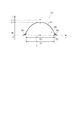
本実施形態の第1の光学素子611は、第1の実施形態の第1の光学素子111の底面200の形状を変形したものである。図6は図2(a)と対応する平面模式図であり、同一の構成については、符号や説明等を省略する。図6(a)及び図6(b)は同一の光学素子611を示す平面模式図である。光学素子611は、底面600を有している。底面600は、図2(a)の光学素子111の底面200が有していた辺211、215に相当する辺を有していない。
本実施形態の第1の光学素子711は、第1の実施形態の第1の光学素子111の底面200の形状を変形したものである。図7は、図2(a)と対応する平面模式図であり、同一の構成については、符号や説明等を省略する。
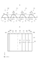
本実施形態では、図1の第3の光学素子113と第4の光学素子114が、第1の光学素子111とは異なる形状である場合を説明する。ここで、第1の光学素子811は、図2(b)の第1の光学素子111と同一の構造である。図8(a)は、第1〜第4の光学素子811〜814の断面模式図であり、それぞれ、図2(b)の断面と対応する断面831〜断面834を示している。断面831〜834に示すように、第1〜第4の光学素子814は、それぞれ異なる形状を有している。第1〜第4の光学素子811〜814において、それぞれは、等しい第3の高さH3及び第1の長さL1を有する。
本実施形態は、第4の実施形態の区分の境界に関するものである。図10は、複数の区分の境界を拡大した平面模式図である。
本実施形態の光学素子アレイについて、図11を用いて説明する。本実施形態は、第4の実施形態とは複数の光学素子の形状の異ならせ方が異なる。図11は、第1の光学素子1111、第3の光学素子1113、第4の光学素子114の平面模式図である。第2の光学素子については、第4の実施形態と同様であるので図示や説明を省略する。
本実施形態では、上述した光学素子アレイを固体撮像装置に適用した場合について説明する。本実施形態において、固体撮像装置はCMOSセンサである。
111 光学素子
P1 第1の位置
P2 第2の位置
W1 第1の幅
W2 第2の幅
H1 第1の高さ
H2 第2の高さ
R1 第1の曲率半径
R2 第2の曲率半径
Claims (18)
- 複数の光学素子を有する光学素子アレイにおいて、
前記複数の光学素子は、第1の方向に沿って配列し、前記複数の光学素子が配されたアレイ領域の中心から前記第1の方向に沿って第1の距離だけ離れて位置する第1の光学素子を含み、
前記第1の光学素子は、
前記第1の方向と前記第1の方向に直交する第2の方向を含む面に投影された前記第1の光学素子の外縁について、前記第1の光学素子内の前記第1の方向における第1の位置にて、前記第2の方向に沿った第1の幅と、前記第1の光学素子内の前記第1の方向における前記第1の位置よりも前記アレイ領域の中心から離れて位置する第2の位置にて、前記第2の方向に沿った、前記第1の幅よりも狭い第2の幅を有し、
前記第1の光学素子は、
前記第1の位置にて、前記第2の方向に沿った第1の断面をとった場合に、第1の曲率半径と、前記第1の断面において最も高い第1の高さを有し、
前記第2の位置にて、前記第2の方向に沿った第2の断面をとった場合に、前記第1の曲率半径よりも大きな第2の曲率半径と、前記第2の断面において最も高く、前記第1の高さよりも低い第2の高さを有し、
前記投影された前記第1の光学素子の外縁は、前記アレイ領域の中心から最も離れた位置で前記第2の方向に沿った辺を備えることを特徴とする光学素子アレイ。 - 前記第1の方向において、前記第1の光学素子は第1の長さを有し、
前記第1の方向において、前記第1の光学素子の前記アレイ領域の中心に最も近い部分は第3の位置にあり、前記第1の光学素子の前記アレイ領域の中心に最も遠い部分は第4の位置にあることを特徴とする請求項1に記載の光学素子アレイ。 - 前記第1の方向において、前記第1の位置は前記第3の位置から前記第1の長さの半分より近い距離にあり、前記第2の位置は、前記第3の位置から前記第1の長さの半分以上の距離にある、または、
前記第1の方向において、前記第1の位置は前記第3の位置から前記第1の長さの半分以下の距離にあり、前記第2の位置は、前記第3の位置から前記第1の長さの半分より離れた距離にあることを特徴とする請求項2に記載の光学素子アレイ。 - 前記第1の方向において、前記投影された前記第1の光学素子の外縁は、第5の位置にて、前記第2の方向に沿った幅の中で最も広い幅を有し、
前記第1の方向において、前記第5の位置は、前記第3の位置から前記第1の長さの半分以上の位置であり、前記第1の位置と前記第2の位置の間の位置であることを特徴とする請求項2又は3に記載の光学素子アレイ。 - 前記投影された前記第1の光学素子の外縁は、前記投影された前記第1の光学素子の外縁の外周を接して囲む矩形の面積に対して、80%以上の面積を有することを特徴とする請求項1乃至4のいずれか1項に記載の光学素子アレイ。
- 前記複数の光学素子は、前記アレイ領域の中心から前記第1の方向に沿って前記第1の距離より小さい第2の距離に位置する第2の光学素子を含み、
前記第2の光学素子は、前記第1の方向と、前記第1の方向に直交する第2の方向を含む面に、投影された前記第2の光学素子の外縁を有し、
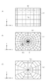
前記第2の光学素子は、前記第1の方向における前記第2の光学素子の投影された前記第2の光学素子の外縁の中心にて、最も高い高さを有することを特徴とする請求項1乃至5のいずれか1項に記載の光学素子アレイ。 - 前記第1の方向と前記第2の方向を含む面において、前記アレイ領域は、複数の区分から構成され、
前記複数の区分は、複数の前記第1の光学素子が設けられている第1の区分と、前記第1の区分よりも前記アレイ領域の中心に対して近い位置にあり、複数の前記第2の光学素子が設けられている第2の区分を含むことを特徴とする請求項6に記載の光学素子アレイ。 - 前記第1の方向と前記第2の方向を含む面において、前記第1の区分及び前記第2の区分は、前記第1の区分の前記第1の方向の長さが、前記第2の区分の前記第1の方向の長さよりも短いことを特徴とする請求項7に記載の光学素子アレイ。
- 前記第1の方向と前記第2の方向を含む面において、前記第1の区分及び前記第2の区分は、同心円形状を有することを特徴とする請求項8に記載の光学素子アレイ。
- 前記第1の方向と前記第2の方向を含む面において、前記第1の区分及び前記第2の区分は、帯形状を有することを特徴とする請求項7に記載の光学素子アレイ。
- 前記第1の方向と前記第2の方向を含む面において、前記第1の区分と前記第2の区分は、前記第1の区分と前記第2の区分の境界に、緩衝領域を有し、
前記緩衝領域には、前記第1の光学素子と前記第2の光学素子が設けられていることを特徴とする請求項7乃至10のいずれか1項に記載の光学素子アレイ。 - 前記第2の光学素子の体積に対する前記第1の光学素子の体積の比は、95%以上105%以下であることを特徴とする請求項6乃至11のいずれか1項に記載の光学素子アレイ。
- 前記複数の光学素子は、前記アレイ領域の中心から前記第1の方向に沿って前記第1の距離より大きい第3の距離だけ離れて位置する第3の光学素子を含み、
前記第1の光学素子は、前記第1の方向において、前記投影された前記第1の光学素子の外縁の中心から第4の距離だけ離れて位置する頂点を有し、
前記第3の光学素子は、前記第1の方向と前記第2の方向を有する面に投影された前記第3の光学素子の外縁を有し、
前記第3の光学素子は、前記第1の方向において、前記投影された前記第3の光学素子の外縁の中心から前記第4の距離より大きな第5の距離だけ離れて位置する頂点を有することを特徴とする請求項1乃至12のいずれか1項に記載の光学素子アレイ。 - 前記アレイ領域は、複数の区分により構成され、
前記複数の区分は、複数の前記第1の光学素子が設けられている第1の区分と、前記第1の区分よりも前記アレイ領域の中心から離れて位置し、複数の前記第3の光学素子が設けられている第3の区分を含むことを特徴とする請求項13に記載の光学素子アレイ。 - 前記複数の光学素子は、更に、前記第2の方向に配されていることを特徴とする請求項1乃至14のいずれか1項に記載の光学素子アレイ。
- 請求項1乃至15のいずれか1項に記載の光学素子アレイと、
前記複数の光学素子のそれぞれに対応してそれぞれが設けられた複数の画素を有する固体撮像装置。 - 前記第1の方向において、前記複数の光学素子の中心の間隔と、前記複数の画素の中心の間隔が等しいことを特徴とする請求項16に記載の固体撮像装置。
- 前記第1の方向において、前記複数の光学素子の中心の間隔と、前記複数の画素の中心の間隔が異なることを特徴とする請求項16に記載の固体撮像装置。
Priority Applications (6)
| Application Number | Priority Date | Filing Date | Title |
|---|---|---|---|
| JP2013137050A JP5791664B2 (ja) | 2013-06-28 | 2013-06-28 | 光学素子アレイ、及び固体撮像装置 |
| EP14172669.5A EP2819172B1 (en) | 2013-06-28 | 2014-06-17 | Optical element array and solid-state imaging device including the array |
| US14/313,857 US9285510B2 (en) | 2013-06-28 | 2014-06-24 | Optical element array and solid-state imaging device including the array |
| CN201410299663.8A CN104252013B (zh) | 2013-06-28 | 2014-06-27 | 光学元件阵列和包括该阵列的固态成像装置 |
| CN201510796237.XA CN105319622B (zh) | 2013-06-28 | 2014-06-27 | 光学元件阵列和包括该阵列的固态成像装置 |
| US15/009,646 US9599754B2 (en) | 2013-06-28 | 2016-01-28 | Optical element array and solid-state imaging device including the array |
Applications Claiming Priority (1)
| Application Number | Priority Date | Filing Date | Title |
|---|---|---|---|
| JP2013137050A JP5791664B2 (ja) | 2013-06-28 | 2013-06-28 | 光学素子アレイ、及び固体撮像装置 |
Related Child Applications (1)
| Application Number | Title | Priority Date | Filing Date |
|---|---|---|---|
| JP2015156107A Division JP6072164B2 (ja) | 2015-08-06 | 2015-08-06 | 光学素子アレイ、及び固体撮像装置 |
Publications (3)
| Publication Number | Publication Date |
|---|---|
| JP2015012488A JP2015012488A (ja) | 2015-01-19 |
| JP2015012488A5 JP2015012488A5 (ja) | 2015-03-12 |
| JP5791664B2 true JP5791664B2 (ja) | 2015-10-07 |
Family
ID=51032926
Family Applications (1)
| Application Number | Title | Priority Date | Filing Date |
|---|---|---|---|
| JP2013137050A Expired - Fee Related JP5791664B2 (ja) | 2013-06-28 | 2013-06-28 | 光学素子アレイ、及び固体撮像装置 |
Country Status (4)
| Country | Link |
|---|---|
| US (2) | US9285510B2 (ja) |
| EP (1) | EP2819172B1 (ja) |
| JP (1) | JP5791664B2 (ja) |
| CN (2) | CN105319622B (ja) |
Families Citing this family (6)
| Publication number | Priority date | Publication date | Assignee | Title |
|---|---|---|---|---|
| JP2016058538A (ja) * | 2014-09-09 | 2016-04-21 | キヤノン株式会社 | 固体撮像装置およびカメラ |
| JP6506614B2 (ja) * | 2015-05-14 | 2019-04-24 | キヤノン株式会社 | 固体撮像装置およびカメラ |
| WO2018103819A1 (en) * | 2016-12-05 | 2018-06-14 | Photonic Sensors & Algorithms, S.L. | Microlens array |
| US10777609B1 (en) * | 2019-04-01 | 2020-09-15 | Visera Technologies Company Limited | Optical devices with light collection elements formed in pixels |
| JP7353834B2 (ja) | 2019-07-12 | 2023-10-02 | キヤノン株式会社 | 表示装置および表示システム |
| JP2022141058A (ja) | 2021-03-15 | 2022-09-29 | オムロン株式会社 | 表示切替装置 |
Family Cites Families (22)
| Publication number | Priority date | Publication date | Assignee | Title |
|---|---|---|---|---|
| JPH04252579A (ja) | 1991-01-28 | 1992-09-08 | Sony Corp | 固体撮像装置 |
| JPH11317836A (ja) * | 1998-02-02 | 1999-11-16 | Sharp Corp | 光導波路型縮小光学イメ―ジセンサ |
| JP2000039503A (ja) | 1998-07-22 | 2000-02-08 | Matsushita Electric Ind Co Ltd | レンズアレイ |
| JP2002120230A (ja) * | 2000-10-13 | 2002-04-23 | Canon Inc | マイクロ構造体、及びその作製方法 |
| JP4161602B2 (ja) * | 2002-03-27 | 2008-10-08 | セイコーエプソン株式会社 | マイクロレンズアレイおよびその製造方法並びに光学装置 |
| JP5031173B2 (ja) * | 2003-03-26 | 2012-09-19 | 大日本印刷株式会社 | 撮像装置と撮像装置におけるマイクロレンズの形成方法 |
| JP2004347693A (ja) | 2003-05-20 | 2004-12-09 | Seiko Epson Corp | マイクロレンズアレイ、空間光変調装置、プロジェクタ及びマイクロレンズアレイの製造方法 |
| JP4796287B2 (ja) * | 2004-08-06 | 2011-10-19 | パナソニック株式会社 | 固体撮像装置 |
| JP4882224B2 (ja) * | 2004-11-26 | 2012-02-22 | ソニー株式会社 | 固体撮像装置の製造方法 |
| KR100693927B1 (ko) * | 2005-02-03 | 2007-03-12 | 삼성전자주식회사 | 마이크로 렌즈 제조방법, 마이크로 렌즈 어레이 제조방법및 이미지 센서 제조방법 |
| JP2007335723A (ja) * | 2006-06-16 | 2007-12-27 | Fujifilm Corp | 固体撮像素子用マイクロレンズ及びその製造方法 |
| JP2008244225A (ja) | 2007-03-28 | 2008-10-09 | Matsushita Electric Ind Co Ltd | 固体撮像装置,グレースケールマスクおよびカラーフィルタならびにマイクロレンズ |
| KR20100080785A (ko) * | 2007-09-06 | 2010-07-12 | 쓰리엠 이노베이티브 프로퍼티즈 컴파니 | 광 출력의 영역 제어를 제공하는 광 추출 구조물을 갖는 도광체 |
| US8228606B2 (en) * | 2008-01-08 | 2012-07-24 | United Microelectronics Corp. | Contiguous microlens array and photomask for defining the same |
| JP5269454B2 (ja) * | 2008-03-25 | 2013-08-21 | 株式会社東芝 | 固体撮像素子 |
| JP5233404B2 (ja) * | 2008-05-19 | 2013-07-10 | 凸版印刷株式会社 | 濃度分布マスクの製造方法及びマイクロレンズアレイの製造方法 |
| JP5131164B2 (ja) | 2008-11-19 | 2013-01-30 | 凸版印刷株式会社 | マイクロレンズアレイと濃度分布マスク及びその設計装置 |
| JP2010245202A (ja) | 2009-04-03 | 2010-10-28 | Panasonic Corp | 固体撮像装置およびその製造方法 |
| JP5365353B2 (ja) | 2009-06-08 | 2013-12-11 | 凸版印刷株式会社 | 濃度分布マスク |
| DE102009049387B4 (de) | 2009-10-14 | 2016-05-25 | Fraunhofer-Gesellschaft zur Förderung der angewandten Forschung e.V. | Vorrichtung, Bildverarbeitungsvorrichtung und Verfahren zur optischen Abbildung |
| CN101820237B (zh) * | 2010-03-16 | 2013-11-27 | 香港应用科技研究院有限公司 | 小型光伏装置 |
| JP5591851B2 (ja) * | 2012-03-15 | 2014-09-17 | 株式会社東芝 | 固体撮像装置および携帯情報端末 |
-
2013
- 2013-06-28 JP JP2013137050A patent/JP5791664B2/ja not_active Expired - Fee Related
-
2014
- 2014-06-17 EP EP14172669.5A patent/EP2819172B1/en active Active
- 2014-06-24 US US14/313,857 patent/US9285510B2/en active Active
- 2014-06-27 CN CN201510796237.XA patent/CN105319622B/zh not_active Expired - Fee Related
- 2014-06-27 CN CN201410299663.8A patent/CN104252013B/zh active Active
-
2016
- 2016-01-28 US US15/009,646 patent/US9599754B2/en active Active
Also Published As
| Publication number | Publication date |
|---|---|
| CN104252013B (zh) | 2016-05-25 |
| EP2819172B1 (en) | 2017-03-22 |
| CN104252013A (zh) | 2014-12-31 |
| CN105319622A (zh) | 2016-02-10 |
| US9285510B2 (en) | 2016-03-15 |
| US20160146981A1 (en) | 2016-05-26 |
| US9599754B2 (en) | 2017-03-21 |
| EP2819172A1 (en) | 2014-12-31 |
| JP2015012488A (ja) | 2015-01-19 |
| US20150001662A1 (en) | 2015-01-01 |
| CN105319622B (zh) | 2018-06-12 |
Similar Documents
| Publication | Publication Date | Title |
|---|---|---|
| JP5791664B2 (ja) | 光学素子アレイ、及び固体撮像装置 | |
| JP6292814B2 (ja) | 光学素子アレイ、光電変換装置、及び撮像システム | |
| JP5636509B2 (ja) | カラー撮像装置 | |
| JP2015028960A (ja) | 固体撮像装置および電子機器 | |
| US20160334621A1 (en) | Design method for optical element, and optical element array | |
| JP2016149417A (ja) | 固体撮像装置、固体撮像装置の製造方法及び撮像システム | |
| JPWO2006040963A1 (ja) | 固体撮像装置 | |
| US20090242735A1 (en) | Solid-state image pickup device and mask manufacturing method | |
| JP6072164B2 (ja) | 光学素子アレイ、及び固体撮像装置 | |
| US20120262611A1 (en) | Method for calculating shift amount of image pickup element and image pickup element | |
| US20160141323A1 (en) | Solid-state imaging apparatus | |
| JP6492395B2 (ja) | 撮像素子および撮像装置 | |
| JP2017079243A (ja) | 固体撮像装置及びカメラ | |
| JP6195369B2 (ja) | 固体撮像装置、カメラ、および、固体撮像装置の製造方法 | |
| JP2012084873A (ja) | 固体撮像素子の製造方法 | |
| JP4419658B2 (ja) | 固体撮像装置 | |
| US20230296978A1 (en) | Photomask, method for manufacturing lens, and method for manufacturing photodetector | |
| JP4941221B2 (ja) | 固体撮像素子およびそれを用いた撮像装置 | |
| WO2022018981A1 (ja) | 固体撮像装置、固体撮像装置の製造方法、および電子機器 | |
| JP2019134170A (ja) | 撮像素子および撮像装置 |
Legal Events
| Date | Code | Title | Description |
|---|---|---|---|
| A521 | Request for written amendment filed |
Free format text: JAPANESE INTERMEDIATE CODE: A523 Effective date: 20150127 |
|
| A621 | Written request for application examination |
Free format text: JAPANESE INTERMEDIATE CODE: A621 Effective date: 20150127 |
|
| A871 | Explanation of circumstances concerning accelerated examination |
Free format text: JAPANESE INTERMEDIATE CODE: A871 Effective date: 20150205 |
|
| A975 | Report on accelerated examination |
Free format text: JAPANESE INTERMEDIATE CODE: A971005 Effective date: 20150220 |
|
| A131 | Notification of reasons for refusal |
Free format text: JAPANESE INTERMEDIATE CODE: A131 Effective date: 20150317 |
|
| A521 | Request for written amendment filed |
Free format text: JAPANESE INTERMEDIATE CODE: A523 Effective date: 20150518 |
|
| TRDD | Decision of grant or rejection written | ||
| A01 | Written decision to grant a patent or to grant a registration (utility model) |
Free format text: JAPANESE INTERMEDIATE CODE: A01 Effective date: 20150707 |
|
| A61 | First payment of annual fees (during grant procedure) |
Free format text: JAPANESE INTERMEDIATE CODE: A61 Effective date: 20150804 |
|
| R151 | Written notification of patent or utility model registration |
Ref document number: 5791664 Country of ref document: JP Free format text: JAPANESE INTERMEDIATE CODE: R151 |
|
| LAPS | Cancellation because of no payment of annual fees |