JP5574656B2 - カーテンエアバッグ装置 - Google Patents
カーテンエアバッグ装置 Download PDFInfo
- Publication number
- JP5574656B2 JP5574656B2 JP2009221686A JP2009221686A JP5574656B2 JP 5574656 B2 JP5574656 B2 JP 5574656B2 JP 2009221686 A JP2009221686 A JP 2009221686A JP 2009221686 A JP2009221686 A JP 2009221686A JP 5574656 B2 JP5574656 B2 JP 5574656B2
- Authority
- JP
- Japan
- Prior art keywords
- protector
- cushion
- curtain airbag
- airbag device
- vehicle
- Prior art date
- Legal status (The legal status is an assumption and is not a legal conclusion. Google has not performed a legal analysis and makes no representation as to the accuracy of the status listed.)
- Active
Links
Images


Classifications
-
- B—PERFORMING OPERATIONS; TRANSPORTING
- B60—VEHICLES IN GENERAL
- B60R—VEHICLES, VEHICLE FITTINGS, OR VEHICLE PARTS, NOT OTHERWISE PROVIDED FOR
- B60R21/00—Arrangements or fittings on vehicles for protecting or preventing injuries to occupants or pedestrians in case of accidents or other traffic risks
- B60R21/02—Occupant safety arrangements or fittings, e.g. crash pads
- B60R21/16—Inflatable occupant restraints or confinements designed to inflate upon impact or impending impact, e.g. air bags
- B60R21/23—Inflatable members
- B60R21/231—Inflatable members characterised by their shape, construction or spatial configuration
- B60R21/232—Curtain-type airbags deploying mainly in a vertical direction from their top edge
-
- B—PERFORMING OPERATIONS; TRANSPORTING
- B60—VEHICLES IN GENERAL
- B60R—VEHICLES, VEHICLE FITTINGS, OR VEHICLE PARTS, NOT OTHERWISE PROVIDED FOR
- B60R21/00—Arrangements or fittings on vehicles for protecting or preventing injuries to occupants or pedestrians in case of accidents or other traffic risks
- B60R21/02—Occupant safety arrangements or fittings, e.g. crash pads
- B60R21/16—Inflatable occupant restraints or confinements designed to inflate upon impact or impending impact, e.g. air bags
- B60R21/20—Arrangements for storing inflatable members in their non-use or deflated condition; Arrangement or mounting of air bag modules or components
- B60R21/201—Packaging straps or envelopes for inflatable members
-
- B—PERFORMING OPERATIONS; TRANSPORTING
- B60—VEHICLES IN GENERAL
- B60R—VEHICLES, VEHICLE FITTINGS, OR VEHICLE PARTS, NOT OTHERWISE PROVIDED FOR
- B60R21/00—Arrangements or fittings on vehicles for protecting or preventing injuries to occupants or pedestrians in case of accidents or other traffic risks
- B60R21/02—Occupant safety arrangements or fittings, e.g. crash pads
- B60R21/16—Inflatable occupant restraints or confinements designed to inflate upon impact or impending impact, e.g. air bags
- B60R21/20—Arrangements for storing inflatable members in their non-use or deflated condition; Arrangement or mounting of air bag modules or components
- B60R21/213—Arrangements for storing inflatable members in their non-use or deflated condition; Arrangement or mounting of air bag modules or components in vehicle roof frames or pillars
-
- B—PERFORMING OPERATIONS; TRANSPORTING
- B60—VEHICLES IN GENERAL
- B60R—VEHICLES, VEHICLE FITTINGS, OR VEHICLE PARTS, NOT OTHERWISE PROVIDED FOR
- B60R21/00—Arrangements or fittings on vehicles for protecting or preventing injuries to occupants or pedestrians in case of accidents or other traffic risks
- B60R21/02—Occupant safety arrangements or fittings, e.g. crash pads
- B60R21/16—Inflatable occupant restraints or confinements designed to inflate upon impact or impending impact, e.g. air bags
- B60R21/20—Arrangements for storing inflatable members in their non-use or deflated condition; Arrangement or mounting of air bag modules or components
- B60R21/217—Inflation fluid source retainers, e.g. reaction canisters; Connection of bags, covers, diffusers or inflation fluid sources therewith or together
- B60R21/2171—Inflation fluid source retainers, e.g. reaction canisters; Connection of bags, covers, diffusers or inflation fluid sources therewith or together specially adapted for elongated cylindrical or bottle-like inflators with a symmetry axis perpendicular to the main direction of bag deployment, e.g. extruded reaction canisters
-
- B—PERFORMING OPERATIONS; TRANSPORTING
- B60—VEHICLES IN GENERAL
- B60R—VEHICLES, VEHICLE FITTINGS, OR VEHICLE PARTS, NOT OTHERWISE PROVIDED FOR
- B60R21/00—Arrangements or fittings on vehicles for protecting or preventing injuries to occupants or pedestrians in case of accidents or other traffic risks
- B60R21/02—Occupant safety arrangements or fittings, e.g. crash pads
- B60R21/16—Inflatable occupant restraints or confinements designed to inflate upon impact or impending impact, e.g. air bags
- B60R2021/161—Inflatable occupant restraints or confinements designed to inflate upon impact or impending impact, e.g. air bags characterised by additional means for controlling deployment trajectory
Landscapes
- Engineering & Computer Science (AREA)
- Mechanical Engineering (AREA)
- Air Bags (AREA)
Description
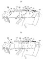
図1は、本発明によるカーテンエアバッグ装置の第1実施形態を例示する図である。図1(a)はカーテンエアバッグ装置100の未展開時、図1(b)はカーテンエアバッグ装置100の展開時をそれぞれ例示する。以下すべての実施形態を図1のように車両102の右側面用のカーテンエアバッグ装置として説明するが、左側面用のカーテンエアバッグ装置も同様の対称な構造を有する。
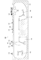
図4は、図3(a)のプロテクタの詳細を例示する図である。図4(a)(b)はそれぞれ、車内側および車外側からプロテクタ180を見た図である。
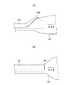
図8は、図1のプロテクタのうち、インフレータ120に近い第1の端部180Aの形状を例示する図である。図8(a)は第1の端部180Aを車内側から見た図、図8(b)は第1の端部180Aの斜視図、図8(c)は第1の端部180Aの断面形状の推移を例示する図である。図8(c)に例示するように、プロテクタ180の断面は、インフレータ120に近い第1の端部180Aにて、その断面をなす開曲線の車内側の端点Pがなだらかに上昇する。すなわち、第1の端部180Aに接近するに従って、開曲線の形状は、図8(c)に例示するように断面I−I、断面II−II、断面III−IIIと順次変化する。その結果、開曲線の間口が距離D1から距離D2に拡大している。このようなフレア状(ラッパ状)の第1の端部180Aの形状を「チョーク防止形状」と呼ぶ。
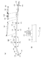
図12は、本発明によるカーテンエアバッグ装置の第2実施形態を例示する斜視図である。以下、第1の実施形態と共通する構成については、説明を省略する。本実施形態にかかるカーテンエアバッグ装置200のプロテクタ210の特徴は、図12に例示するように、その外面における長手方向の軌道上に、車体に固定される、プロテクタ280と一体の複数のプロテクタタブ220を有することである。ほとんど一直線状の軌道上に設けられた複数のプロテクタタブ220を車体に固定することとなるので、クッション部140は、組付時によじれることがない。
図14は本発明によるカーテンエアバッグ装置の第3実施形態を例示する斜視図であり、図15は図14のD−D断面図である。以下、本実施形態にかかるカーテンエアバッグ装置300について、第2の実施形態と共通する構成については、説明を省略する。第3の実施形態におけるプロテクタ250の特徴は、車室天井242の上面に当接する延伸部240をさらに有することである。図14に例示するように、延伸部240は、剛性の高いプロテクタタブ220の直下に設けるとよい。かかる構成によれば、乗員が何らかの理由で車室天井242に接触するなどした場合に、天井242のブカつきを防止可能である。延伸部240は車室天井242に常時当接している必要はなく、1〜3mmのクリアランスがあってもよい。
図16は本発明によるカーテンエアバッグ装置の第4実施形態を例示する斜視図である。本実施形態にかかるカーテンエアバッグ装置400のプロテクタ480は、プロテクタタブ220とクッションタブ170との位置がずれていて、第3実施形態(図13)のように両者を重ね合わせて共締めすることが不可能なタイプである。かかる場合には、プロテクタタブ220とクッションタブ170とをそれぞれ別個に車体に固定する。
図17は本発明によるカーテンエアバッグ装置の第5実施形態を例示する図であり、図16のカーテンエアバッグ装置400を変形したものを、車両前後方向に見た図である。本実施形態にかかるカーテンエアバッグ装置500では、プロテクタ510のプロテクタタブ520を単独で車体に固定する方法を例示している。カーテンエアバッグ装置500のプロテクタタブ520の車外側には、パンタグラフ状固定具530が一体成形されている。図17(a)のように、パンタグラフ状固定具530は、ルーフサイドレール110に設けられた孔に挿入されるときには横長の菱形になり、図17(b)に例示するように、孔の反対側で縦長になりプロテクタ500は固定可能となる。縦長になったパンタグラフ状固定具530にさらにピンまたはネジ等を入れることで、パンタグラフ状固定具530は再び孔より小さくならないので、より強固な固定が可能となる。
図18は本発明によるカーテンエアバッグ装置の第6実施形態を例示する図であり、図16のカーテンエアバッグ装置400を変形したものを、車両前後方向に見た図である。本実施形態にかかるカーテンエアバッグ装置600では、プロテクタ610のプロテクタタブ620を単独で車体に固定する方法を例示している。カーテンエアバッグ装置600のプロテクタタブ620は、アンカ状固定具630によって車体に固定される。図18のように、アンカ状固定具630は、ルーフサイドレール110に設けられた孔に挿入されるときには周囲の羽630Aを引っ込めて干渉しないようにし、孔の反対側で弾性力を用いて羽630Aを露出させ、孔から抜けなくして固定を完成する。
図19は本発明によるカーテンエアバッグ装置の第7実施形態を例示する図である。本実施形態にかかるカーテンエアバッグ装置700では、図19(a)に例示するように、巻回されているクッション部140の2つの折返し部の付近に、プロテクタ730とクッション部140とを正しく位置合わせするためのライン710、720が引かれている。
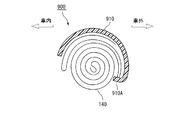
図20は本発明によるカーテンエアバッグ装置の第8実施形態を例示する図であり、本実施形態にかかるカーテンエアバッグ装置800を車両前後方向に沿って見た図である。本実施形態も図16のカーテンエアバッグ装置400を変形したものである。すなわち、プロテクタタブ220とクッションタブ170との位置がずれていて、両者を重ね合わせて共締めすることが不可能であるため、クッション部140をプロテクタに位置合わせする必要があるタイプである。
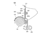
図21は本発明によるカーテンエアバッグ装置の第9実施形態を例示する図であり、本実施形態にかかるカーテンエアバッグ装置900を車両前後方向に沿って見た図である。本実施形態も図16のカーテンエアバッグ装置400を変形したものである。すなわち、プロテクタタブ220とクッションタブ170との位置がずれていて、両者を重ね合わせて共締めすることが不可能であるため、クッション部140をプロテクタに位置合わせする必要があるタイプである。
102 …車両
110 …ルーフサイドレール
120 …インフレータ
140 …クッション部
142 …メインダクト
170 …クッションタブ
172 …ボルト穴
174 …固定用金具
176 …角形ボルト穴
180、210、250、510、610、730、810、910 …プロテクタ
180A …第1の端部
180B …第2の端部
192 …アシストグリップブラケット
194 …回転防止部
196 …スリット
220、520、620 …プロテクタタブ
230 …リブ
236 …ウェザーストリップ
238 …エッジ
240 …延伸部
242 …車室天井
Claims (3)
- 車室側面上方に収納されるカーテンエアバッグ装置において、
車両前後方向に延伸し、下端から上端に向かって巻回された状態で収納され、上端に取り付けられたタブで車両のルーフサイドレールに固定され、ガスを供給されて下方へ膨張展開するクッション部と、
前記クッション部を被覆する長尺のプロテクタと、
を備え、
前記プロテクタは、粘着テープで前記クッション部に固定され、下方に開口した弧状の開曲線の断面を有し、前記クッション部が膨張展開初期に前記プロテクタと共に回転しようとすることに対し、前記プロテクタの周辺で車体に固定されていて前記プロテクタには固定されていない固定部材と干渉して前記クッション部および前記プロテクタの当該回転を防止する、該プロテクタと一体の回転防止部を有することを特徴とするカーテンエアバッグ装置。 - 前記回転防止部は前記プロテクタから突出していることを特徴とする請求項1に記載のカーテンエアバッグ装置。
- 当該カーテンエアバッグ装置は、前記巻回された状態のクッション部を前記プロテクタが所定の位置で被覆するよう位置合わせする位置合わせ手段をさらに有することを特徴とする請求項1または2に記載のカーテンエアバッグ装置。
Priority Applications (2)
| Application Number | Priority Date | Filing Date | Title |
|---|---|---|---|
| JP2009221686A JP5574656B2 (ja) | 2009-09-25 | 2009-09-25 | カーテンエアバッグ装置 |
| PCT/JP2010/066582 WO2011037198A1 (ja) | 2009-09-25 | 2010-09-24 | カーテンエアバッグ装置 |
Applications Claiming Priority (1)
| Application Number | Priority Date | Filing Date | Title |
|---|---|---|---|
| JP2009221686A JP5574656B2 (ja) | 2009-09-25 | 2009-09-25 | カーテンエアバッグ装置 |
Related Child Applications (2)
| Application Number | Title | Priority Date | Filing Date |
|---|---|---|---|
| JP2014093267A Division JP5714746B2 (ja) | 2014-04-30 | 2014-04-30 | カーテンエアバッグ装置 |
| JP2014093266A Division JP5815789B2 (ja) | 2014-04-30 | 2014-04-30 | カーテンエアバッグ装置 |
Publications (2)
| Publication Number | Publication Date |
|---|---|
| JP2012179922A JP2012179922A (ja) | 2012-09-20 |
| JP5574656B2 true JP5574656B2 (ja) | 2014-08-20 |
Family
ID=43795942
Family Applications (1)
| Application Number | Title | Priority Date | Filing Date |
|---|---|---|---|
| JP2009221686A Active JP5574656B2 (ja) | 2009-09-25 | 2009-09-25 | カーテンエアバッグ装置 |
Country Status (2)
| Country | Link |
|---|---|
| JP (1) | JP5574656B2 (ja) |
| WO (1) | WO2011037198A1 (ja) |
Families Citing this family (5)
| Publication number | Priority date | Publication date | Assignee | Title |
|---|---|---|---|---|
| DE102011087449B4 (de) | 2011-11-30 | 2019-04-25 | Autoliv Development Ab | Vorhangairbag für ein Fahrzeug |
| DE102013201880B4 (de) * | 2013-02-05 | 2022-02-17 | Autoliv Development Ab | Aufblasbare Vorhangairbagbaugruppe |
| JP6034762B2 (ja) * | 2013-07-09 | 2016-11-30 | オートリブ ディベロップメント エービー | カーテンエアバッグ装置の製造方法 |
| JP5948296B2 (ja) * | 2013-09-27 | 2016-07-06 | オートリブ ディベロップメント エービー | カーテンエアバッグ装置 |
| JP6768566B2 (ja) | 2017-03-13 | 2020-10-14 | 豊田合成株式会社 | 頭部保護エアバッグ装置 |
Family Cites Families (7)
| Publication number | Priority date | Publication date | Assignee | Title |
|---|---|---|---|---|
| JP3741061B2 (ja) * | 2002-02-27 | 2006-02-01 | 日産自動車株式会社 | 自動車の車体上部の衝撃吸収構造 |
| JP4736665B2 (ja) * | 2005-09-20 | 2011-07-27 | タカタ株式会社 | カーテンエアバッグ取付金具及び取付構造、並びにカーテンエアバッグ装置 |
| EP1772328A3 (en) * | 2005-10-07 | 2008-03-26 | Delphi Korea Corporation | Automobile side airbag guide plate |
| JP2007261293A (ja) * | 2006-03-27 | 2007-10-11 | Nippon Plast Co Ltd | カーテンエアバッグ装置 |
| JP4911760B2 (ja) * | 2006-07-31 | 2012-04-04 | 日本プラスト株式会社 | エアバッグ装置 |
| JP4770791B2 (ja) * | 2007-05-11 | 2011-09-14 | トヨタ自動車株式会社 | 頭部保護エアバッグ装置 |
| JP5137487B2 (ja) * | 2007-07-18 | 2013-02-06 | 日本プラスト株式会社 | エアバッグ装置 |
-
2009
- 2009-09-25 JP JP2009221686A patent/JP5574656B2/ja active Active
-
2010
- 2010-09-24 WO PCT/JP2010/066582 patent/WO2011037198A1/ja active Application Filing
Also Published As
| Publication number | Publication date |
|---|---|
| WO2011037198A1 (ja) | 2011-03-31 |
| JP2012179922A (ja) | 2012-09-20 |
Similar Documents
| Publication | Publication Date | Title |
|---|---|---|
| WO2011037199A1 (ja) | カーテンエアバッグ装置 | |
| JP5582751B2 (ja) | カーテンエアバッグ装置 | |
| JP5595154B2 (ja) | カーテンエアバッグ | |
| KR100895128B1 (ko) | 사이드 커튼 에어백 유닛 | |
| JP5401288B2 (ja) | カーテンエアバッグ装置 | |
| US20140217707A1 (en) | Airbag device | |
| JP5411660B2 (ja) | カーテンエアバッグ装置 | |
| CN107933483B (zh) | 车辆窗帘气囊装置 | |
| US8955874B2 (en) | Cover and airbag device | |
| JP2007276767A (ja) | サイドエアバッグ用案内プレート | |
| JP5038089B2 (ja) | エアバッグ装置 | |
| JP5574656B2 (ja) | カーテンエアバッグ装置 | |
| US20080111354A1 (en) | Apparatus for guiding deployment of curtain airbag for vehicle | |
| JP3893887B2 (ja) | 車両の乗員保護装置 | |
| JP5815789B2 (ja) | カーテンエアバッグ装置 | |
| JP2004074867A (ja) | 頭部保護用エアバック装置 | |
| JP2001163160A (ja) | エアバッグ装置 | |
| JP5714746B2 (ja) | カーテンエアバッグ装置 | |
| JP4226615B2 (ja) | 乗員拘束装置 | |
| JP2008114739A (ja) | カーテンエアバッグ装置を備えた車両の後部構造 | |
| JP2010083240A (ja) | エアバッグ及びエアバッグ装置 | |
| JP5485921B2 (ja) | カバー | |
| JP5552445B2 (ja) | カバー | |
| JP2016120873A (ja) | 自動車用カーテンエアバッグの展開構造 | |
| JP5731111B2 (ja) | カーテンエアバッグ装置 |
Legal Events
| Date | Code | Title | Description |
|---|---|---|---|
| A131 | Notification of reasons for refusal |
Free format text: JAPANESE INTERMEDIATE CODE: A131 Effective date: 20130924 |
|
| A02 | Decision of refusal |
Free format text: JAPANESE INTERMEDIATE CODE: A02 Effective date: 20140204 |
|
| A521 | Request for written amendment filed |
Free format text: JAPANESE INTERMEDIATE CODE: A523 Effective date: 20140430 |
|
| A521 | Request for written amendment filed |
Free format text: JAPANESE INTERMEDIATE CODE: A821 Effective date: 20140513 |
|
| A911 | Transfer to examiner for re-examination before appeal (zenchi) |
Free format text: JAPANESE INTERMEDIATE CODE: A911 Effective date: 20140604 |
|
| TRDD | Decision of grant or rejection written | ||
| A01 | Written decision to grant a patent or to grant a registration (utility model) |
Free format text: JAPANESE INTERMEDIATE CODE: A01 Effective date: 20140624 |
|
| A61 | First payment of annual fees (during grant procedure) |
Free format text: JAPANESE INTERMEDIATE CODE: A61 Effective date: 20140701 |
|
| R150 | Certificate of patent or registration of utility model |
Ref document number: 5574656 Country of ref document: JP Free format text: JAPANESE INTERMEDIATE CODE: R150 |
|
| R250 | Receipt of annual fees |
Free format text: JAPANESE INTERMEDIATE CODE: R250 |
|
| R250 | Receipt of annual fees |
Free format text: JAPANESE INTERMEDIATE CODE: R250 |
|
| R250 | Receipt of annual fees |
Free format text: JAPANESE INTERMEDIATE CODE: R250 |
|
| R250 | Receipt of annual fees |
Free format text: JAPANESE INTERMEDIATE CODE: R250 |
|
| R250 | Receipt of annual fees |
Free format text: JAPANESE INTERMEDIATE CODE: R250 |
|
| R250 | Receipt of annual fees |
Free format text: JAPANESE INTERMEDIATE CODE: R250 |
|
| R250 | Receipt of annual fees |
Free format text: JAPANESE INTERMEDIATE CODE: R250 |