JP5300431B2 - Substrate alignment device - Google Patents
Substrate alignment device Download PDFInfo
- Publication number
- JP5300431B2 JP5300431B2 JP2008293669A JP2008293669A JP5300431B2 JP 5300431 B2 JP5300431 B2 JP 5300431B2 JP 2008293669 A JP2008293669 A JP 2008293669A JP 2008293669 A JP2008293669 A JP 2008293669A JP 5300431 B2 JP5300431 B2 JP 5300431B2
- Authority
- JP
- Japan
- Prior art keywords
- axis
- substrate
- inspected
- stage
- alignment
- Prior art date
- Legal status (The legal status is an assumption and is not a legal conclusion. Google has not performed a legal analysis and makes no representation as to the accuracy of the status listed.)
- Active
Links
Images


Classifications
-
- G—PHYSICS
- G01—MEASURING; TESTING
- G01R—MEASURING ELECTRIC VARIABLES; MEASURING MAGNETIC VARIABLES
- G01R31/00—Arrangements for testing electric properties; Arrangements for locating electric faults; Arrangements for electrical testing characterised by what is being tested not provided for elsewhere
- G01R31/28—Testing of electronic circuits, e.g. by signal tracer
- G01R31/2851—Testing of integrated circuits [IC]
- G01R31/2855—Environmental, reliability or burn-in testing
- G01R31/286—External aspects, e.g. related to chambers, contacting devices or handlers
- G01R31/2865—Holding devices, e.g. chucks; Handlers or transport devices
- G01R31/2867—Handlers or transport devices, e.g. loaders, carriers, trays
-
- G—PHYSICS
- G01—MEASURING; TESTING
- G01R—MEASURING ELECTRIC VARIABLES; MEASURING MAGNETIC VARIABLES
- G01R31/00—Arrangements for testing electric properties; Arrangements for locating electric faults; Arrangements for electrical testing characterised by what is being tested not provided for elsewhere
- G01R31/28—Testing of electronic circuits, e.g. by signal tracer
- G01R31/2851—Testing of integrated circuits [IC]
- G01R31/2886—Features relating to contacting the IC under test, e.g. probe heads; chucks
- G01R31/2887—Features relating to contacting the IC under test, e.g. probe heads; chucks involving moving the probe head or the IC under test; docking stations
-
- G—PHYSICS
- G01—MEASURING; TESTING
- G01R—MEASURING ELECTRIC VARIABLES; MEASURING MAGNETIC VARIABLES
- G01R31/00—Arrangements for testing electric properties; Arrangements for locating electric faults; Arrangements for electrical testing characterised by what is being tested not provided for elsewhere
- G01R31/28—Testing of electronic circuits, e.g. by signal tracer
- G01R31/2851—Testing of integrated circuits [IC]
- G01R31/2893—Handling, conveying or loading, e.g. belts, boats, vacuum fingers
-
- G—PHYSICS
- G02—OPTICS
- G02F—OPTICAL DEVICES OR ARRANGEMENTS FOR THE CONTROL OF LIGHT BY MODIFICATION OF THE OPTICAL PROPERTIES OF THE MEDIA OF THE ELEMENTS INVOLVED THEREIN; NON-LINEAR OPTICS; FREQUENCY-CHANGING OF LIGHT; OPTICAL LOGIC ELEMENTS; OPTICAL ANALOGUE/DIGITAL CONVERTERS
- G02F1/00—Devices or arrangements for the control of the intensity, colour, phase, polarisation or direction of light arriving from an independent light source, e.g. switching, gating or modulating; Non-linear optics
- G02F1/01—Devices or arrangements for the control of the intensity, colour, phase, polarisation or direction of light arriving from an independent light source, e.g. switching, gating or modulating; Non-linear optics for the control of the intensity, phase, polarisation or colour
- G02F1/13—Devices or arrangements for the control of the intensity, colour, phase, polarisation or direction of light arriving from an independent light source, e.g. switching, gating or modulating; Non-linear optics for the control of the intensity, phase, polarisation or colour based on liquid crystals, e.g. single liquid crystal display cells
-
- H—ELECTRICITY
- H01—ELECTRIC ELEMENTS
- H01L—SEMICONDUCTOR DEVICES NOT COVERED BY CLASS H10
- H01L21/00—Processes or apparatus adapted for the manufacture or treatment of semiconductor or solid state devices or of parts thereof
- H01L21/67—Apparatus specially adapted for handling semiconductor or electric solid state devices during manufacture or treatment thereof; Apparatus specially adapted for handling wafers during manufacture or treatment of semiconductor or electric solid state devices or components ; Apparatus not specifically provided for elsewhere
- H01L21/68—Apparatus specially adapted for handling semiconductor or electric solid state devices during manufacture or treatment thereof; Apparatus specially adapted for handling wafers during manufacture or treatment of semiconductor or electric solid state devices or components ; Apparatus not specifically provided for elsewhere for positioning, orientation or alignment
Abstract
Description
本発明は、大型のLCD基板等の被検査基板を検査する際に、この被検査基板のプリアライメントを行う被検査基板のアライメント装置に関する。 The present invention relates to an alignment apparatus for a substrate to be inspected that pre-aligns the substrate to be inspected when inspecting a substrate to be inspected such as a large LCD substrate.
LCD基板等の被検査基板を検査する場合はプローバ等の検査装置が用いられる。この検査装置においては、その探針と、被検査基板上の電極とを正確に位置合わせする必要がある。 When inspecting an inspection substrate such as an LCD substrate, an inspection device such as a prober is used. In this inspection apparatus, it is necessary to accurately align the probe and the electrode on the substrate to be inspected.
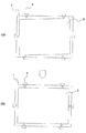
この場合においては、通常、プリアライメントを行った後に、探針と電極とを正確に位置合わせする2段階の調整が行われる。従来のプリアライメントは、図2(A)に示すように、ワークテーブル1に対してガラス基板等の被検査基板2がずれて載置されると、パネルクランプ3が被検査基板2に接触して押し、図2(B)に示すように、設定位置までずらして被検査基板2のプリアライメントを行っていた。 In this case, usually, after pre-alignment, two-stage adjustment is performed to accurately align the probe and the electrode. In the conventional pre-alignment, as shown in FIG. 2A, when the inspection substrate 2 such as a glass substrate is shifted with respect to the work table 1, the panel clamp 3 comes into contact with the inspection substrate 2. As shown in FIG. 2 (B), the substrate to be inspected 2 is pre-aligned by shifting to the set position.
この場合、パネルクランプ3で被検査基板2に直接接触するため、被検査基板2が欠けることがあった。また、被検査基板2の寸法が大きくなると、パネルクランプ3で押し切れない場合もあった。 In this case, since the panel clamp 3 is in direct contact with the substrate 2 to be inspected, the substrate 2 to be inspected may be missing. Further, when the size of the substrate to be inspected 2 is increased, the panel clamp 3 sometimes cannot be pushed completely.
一方、特許文献1のように、ロボットアームに被検査基板を載せた状態で、プリアライメントを行う例がある。また、特許文献2のように、検出機構でLCD基板の縁を検出してX軸方向の傾きを検出し、その傾きに応じて載置機構を回転させてLCD基板の向きを合わせてプリアライメントを行う例がある。
ところが、上記特許文献1の被検査基板のアライメント方法では、ロボットアームに載せられる大きさの被検査基板に限られ、大きな寸法の被検査基板のプリアライメントを行うことはできない。
However, the method for aligning a substrate to be inspected in
また、特許文献2のLCD基板のアライメント方法では、原理的には大きな寸法の被検査基板のプリアライメントを行うことも可能であるが、特許文献2は原理のみであり、具体的にどのような機構で行うのかは不明である。 Further, in the alignment method of the LCD substrate of Patent Document 2, in principle, it is possible to perform pre-alignment of a substrate to be inspected having a large size. It is unclear whether the mechanism is used.
本発明はこのような問題点に鑑みてなされたもので、大きな寸法の被検査基板に対して具体的にプリアライメントを行うことができる被検査基板のアライメント装置を提供することを目的とする。 The present invention has been made in view of such problems, and an object of the present invention is to provide an alignment apparatus for a substrate to be inspected that can specifically perform pre-alignment on a substrate to be inspected having a large size.
本発明に係るアライメント装置は前記課題を解決するためになされたもので、X軸方向に延ばして構成され被検査基板をX軸方向へ移動可能に且つθ軸方向に回転可能に支持するXθ軸ワークステージと、当該Xθ軸ワークステージと別部材として構成されてこのXθ軸ワークステージの上方にY軸方向に掛け渡して設けられX軸プリアライメントセンサ及びY軸プリアライメントセンサをY軸方向及びZ軸方向へ移動可能に支持するYZ軸コンタクトステージと、前記Xθ軸ワークステージ及びYZ軸コンタクトステージを制御する制御部とを備え、前記Xθ軸ワークステージが、X軸方向に延びる骨組みである架台と、前記被検査基板を支持するワークテーブルと、当該ワークテーブルの下側面に設けられてワークテーブルを回転させるθ軸回転機構と、前記架台に支持されて前記θ軸回転機構を支持し当該θ軸回転機構を介して前記ワークテーブルをX軸方向に移動させるX軸直動機構とを備え、前記YZ軸コンタクトステージが、前記Xθ軸ワークステージの上方にY軸方向に掛け渡して設けられた支持アーム部と、当該支持アーム部に取り付けられて前記Xθ軸ワークステージの上方に位置するY軸直動機構と、当該Y軸直動機構によってY軸方向に移動可能に支持された複数のコンタクトステージ板と、当該複数のコンタクトステージ板のうちの一方の端部側のコンタクトステージ板に設けられて前記被検査基板のX軸方向の位置を検出する第1のX軸プリアライメントセンサと、他方の端部側のコンタクトステージ板に設けられて前記被検査基板のX軸方向の位置を検出する第2のX軸プリアライメントセンサ及びY軸方向の位置を検出するY軸プリアライメントセンサと、前記各コンタクトステージ板に設けられ前記被検査基板上の電極と接触する探針を有するプローブブロックをZ軸方向に移動可能に支持するZ軸直動機構とを備え、前記制御部が、前記YZ軸コンタクトステージ側の前記Y軸プリアライメントセンサ及び少なくとも2つの前記X軸プリアライメントセンサで検出した前記被検査基板の位置情報を基に、前記Xθ軸ワークステージの前記θ軸回転機構及びX軸直動機構を制御して前記ワークテーブルをX軸方向に移動させると共に適宜回転させて当該被検査基板のプリアライメントを行う機能を備えたことを特徴とするものである。 An alignment apparatus according to the present invention has been made to solve the above-described problems, and is configured to extend in the X-axis direction, and supports the substrate to be inspected so as to be movable in the X-axis direction and rotatable in the θ-axis direction. The work stage and the Xθ-axis work stage are configured as separate members and are provided above the Xθ-axis work stage so as to extend in the Y-axis direction. A YZ-axis contact stage that is movably supported in the axial direction; and a control unit that controls the Xθ-axis work stage and the YZ-axis contact stage, wherein the Xθ-axis work stage is a skeleton that extends in the X-axis direction; , A work table that supports the substrate to be inspected, and a θ axis that is provided on the lower surface of the work table and rotates the work table A YZ-axis contact stage comprising: a rotation mechanism; and an X-axis linear motion mechanism that is supported by the gantry, supports the θ-axis rotation mechanism, and moves the work table in the X-axis direction via the θ-axis rotation mechanism. A support arm portion provided over the Xθ-axis work stage in the Y-axis direction, a Y-axis linear motion mechanism attached to the support arm portion and positioned above the Xθ-axis work stage, A plurality of contact stage plates supported by the Y-axis linear movement mechanism so as to be movable in the Y-axis direction, and the substrate to be inspected provided on a contact stage plate on one end side of the plurality of contact stage plates; to the first and the X-axis pre-alignment sensor for detecting the position of the X-axis direction, is provided in the contact stage plate at the other end side detects the X-axis direction position of the inspection substrate Z-axis probe block having a Y-axis pre-alignment sensor for detecting the position of the second X-axis prealignment sensor and the Y-axis direction, the probe of the contact with the electrode on the substrate to be inspected is provided in each contact stage plate A Z-axis linear motion mechanism that is movably supported in a direction, and the control unit detects the Y-axis pre-alignment sensor on the YZ-axis contact stage side and at least two X-axis pre-alignment sensors. Based on the position information of the substrate, the θ-axis rotation mechanism and the X-axis linear movement mechanism of the Xθ-axis work stage are controlled to move the work table in the X-axis direction and rotate the X-axis work stage as appropriate. It is characterized by having a function of performing alignment.
前記Y軸プリアライメントセンサ及びX軸プリアライメントセンサで検出した前記被検査基板の位置情報を基に、前記Xθ軸ワークステージの前記θ軸回転機構及びX軸直動機構で前記ワークテーブルを調整して被検査基板のプリアライメントを行うため、大型の被検査基板に対しても確実にプリアライメントを行うことができる。 Based on the position information of the substrate to be inspected detected by the Y-axis pre-alignment sensor and the X-axis pre-alignment sensor, the work table is adjusted by the θ-axis rotation mechanism and the X-axis linear motion mechanism of the Xθ-axis work stage. Since the pre-alignment of the substrate to be inspected is performed, the pre-alignment can be reliably performed even for a large substrate to be inspected.
以下、本発明の実施形態に係るアライメント機構について、添付図面を参照しながら説明する。 Hereinafter, an alignment mechanism according to an embodiment of the present invention will be described with reference to the accompanying drawings.
[第1実施形態]
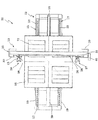
アライメント機構11は図1,3,4に示すように主に、Xθ軸ワークステージ12と、YZ軸コンタクトステージ13とから構成されている。
[First embodiment]
As shown in FIGS. 1, 3, and 4, the
Xθ軸ワークステージ12は、X軸方向に延ばして構成されて、大型のLCD基板等の被検査基板P(図10参照)をX軸方向へ移動可能に且つθ軸方向に回転可能に支持するための装置である。このXθ軸ワークステージ12は主に、架台15と、ワークテーブル16と、θ軸回転機構(図示せず)と、X軸直動機構17とから構成されている。
The Xθ-
架台15は、X軸方向に延ばして構成される台座である。この架台15は、後述するYZ軸コンタクトステージ13の2つの架台30と共にベース板(図示せず)に取り付けられて設置スペースの床部に据え付けられている。架台15は、その上側部にX軸方向に平行に延びる3本の支持フレーム19を備えて構成されている。架台15は、例えば横幅2m、高さ1m、長さ5m程度の大型の部材である。
The
ワークテーブル16は、大型の被検査基板Pを支持するための部材である。ワークテーブル16は、被検査基板Pよりも大きい寸法の四角形板状に形成され、その上側面に被検査基板Pを吸着支持するためのバキューム溝21が設けられている。バキューム溝21は、バキューム装置(図示せず)に接続されて、適宜真空引きされる。
The work table 16 is a member for supporting the large inspected substrate P. The work table 16 is formed in a rectangular plate shape having a size larger than that of the substrate to be inspected P, and a
θ軸回転機構は、ワークテーブル16を回転させるための装置である。θ軸回転機構としては公知の技術を用いることができる。例えば、θ軸回転機構は、扇状の駆動機構によって構成されている。具体的には、θ軸回転機構は、Rガイドレール(リング状のガイドレールの一部)を複数箇所(例えば環状の位置に等間隔に4箇所)設けて、ワークテーブル16を回転可能に支持し、ワークテーブル16の縁部を回動機構でずらしてワークテーブル16を回転させている。回動機構は、ステッピングモータ等の角度調整機能を備えた駆動モータと、この駆動モータに連結されたネジ棒と、このネジ棒にねじ込まれた移動ナットとからなり、この移動ナットがワークテーブル16の縁部に固定されている。そして、駆動モータでネジ棒を設定角度だけ回転させてネジ棒を正確に移動させてワークテーブル16を正確に設定角度だけ回転させる。Rガイドレールは、基板(図示せず)に支持された状態でワークテーブル16の下側面に取り付けられて、ワークテーブル16を回転可能に支持している。 The θ-axis rotation mechanism is a device for rotating the work table 16. A known technique can be used as the θ-axis rotation mechanism. For example, the θ-axis rotation mechanism is configured by a fan-shaped drive mechanism. Specifically, the θ-axis rotating mechanism is provided with a plurality of R guide rails (a part of a ring-shaped guide rail) (for example, four positions at equal intervals in an annular position) to rotatably support the work table 16. Then, the work table 16 is rotated by shifting the edge of the work table 16 by the rotation mechanism. The rotation mechanism includes a drive motor having an angle adjusting function such as a stepping motor, a screw rod connected to the drive motor, and a moving nut screwed into the screw rod. It is fixed to the edge. Then, the screw rod is rotated by the set angle by the drive motor to move the screw rod accurately, and the work table 16 is accurately rotated by the set angle. The R guide rail is attached to the lower surface of the work table 16 while being supported by a substrate (not shown), and rotatably supports the work table 16.
X軸直動機構17は、ワークテーブル16をX軸方向に移動させるための装置である。このX軸直動機構17は、2本のガイドレール22と、1本のリニアモータ23とから構成されている。2本のガイドレール22は、架台15の3本の支持フレーム19のうち両端の支持フレーム19にそれぞれ取り付けられている。このガイドレール22には、ガイド(図示せず)がスライド可能に取り付けられている。このガイドに前記θ軸回転機構の基板が取り付けられることによって、θ軸回転機構に支持されたワークテーブル16を、ガイドレール22に沿ってX軸方向に移動可能に支持している。
The X axis
リニアモータ23は、架台15の3本の支持フレーム19のうち真ん中の支持フレーム19に取り付けられている。このリニアモータ23のスライダはθ軸回転機構の基板に取り付けられている。これにより、ガイドレール22に支持されたθ軸回転機構がリニアモータ23によってX軸方向に移動され、θ軸回転機構に支持されたワークテーブル16が、ガイドレール22に沿ってX軸方向に移動されるようになっている。
The
YZ軸コンタクトステージ13は、後述するX軸プリアライメントセンサ38及びY軸プリアライメントセンサ40等をY軸方向及びZ軸方向へ移動可能に支持するための装置である。YZ軸コンタクトステージ13は、Xθ軸ワークステージ12と別部材として構成されている。YZ軸コンタクトステージ13は、X軸方向に配設されたXθ軸ワークステージ12の上側を跨ぐようにしてY軸方向に配設されている。YZ軸コンタクトステージ13は主に、支持アーム部25と、Y軸直動機構26と、第1Z軸ステージ部27と、第2Z軸ステージ部28とから構成されている。
The YZ-
支持アーム部25は、Xθ軸ワークステージ12の上側を跨ぐように掛け渡される部材である。この支持アーム部25は、2つの架台30と、梁材31とから構成されている。架台30は、YZ軸コンタクトステージ13の両側の脚部を構成する部材である。架台30は、Xθ軸ワークステージ12の両側位置でベース板(図示せず)に取り付けられて設置スペースの床部に据え付けられている。梁材31は、ワークテーブル16の上側位置で水平方向に掛け渡される部材である。梁材31は、その両端部が2つの架台30に固定されている。これにより、支持アーム部25は、ワークテーブル16の上側位置でY軸方向にアーチ状に掛け渡されている。
The
Y軸直動機構26は、第1Z軸ステージ部27及び第2Z軸ステージ部28をY軸方向に移動させるための装置である。このY軸直動機構26は、ガイドレール33と、リニアモータ34とから構成されている。ガイドレール33は、Y軸方向へ延びる梁材31の縦壁に取り付けられている。リニアモータ34は、ガイドレール33と平行にかつ一体的に、梁材31に取り付けられている。ガイドレール33には、リニアモータ34のスライダ35がスライド可能に取り付けられている。スライダ35は、リニアモータ34に2つ設けられている。各スライダ35に、第1Z軸ステージ部27及び第2Z軸ステージ部28がそれぞれ取り付けられている。各スライダ35は、リニアモータ34によって、個別に独立して移動制御されるようになっている。
The Y-axis
第1Z軸ステージ部27は、ワークテーブル16上に載置された被検査基板PのX軸方向の大まかな位置合わせと、その後の被検査基板Pの正確な位置合わせと、被検査基板P上の試験回路E(図4参照)の電極への電気的接触を行うための装置である。第1Z軸ステージ部27は、図5,6に示すように、コンタクトステージ板37と、X軸プリアライメントセンサ38と、Z軸直動機構39と、検索用カメラ40と、アライメントカメラ41と、プローブブロック42とから構成されている。
The first Z-
コンタクトステージ板37は、Y軸直動機構26のスライダ35に直接取り付けられる板材である。コンタクトステージ板37によってZ軸直動機構39等が支持される。
The
X軸プリアライメントセンサ38は、ワークテーブル16上の被検査基板PのX軸方向の大まかな位置調整をするためにワークテーブル16の縁部を検出する第1のX軸プリアライメントセンサである。X軸プリアライメントセンサ38は、図5〜8に示すように、検査光Cを発する発光素子(図7中の投光部で示す部分)と、この発光素子から発せられて被検査基板Pの表面で反射した検査光Cを受光する受光素子(図7中の受光部で示す部分)とを備えて構成されている。これらの発光素子及び受光素子は、その検査光Cが被検査基板Pの縁部に平行になるように配設されている。これは以下の理由による。図8(A)(B)に示すように、検査光Cが被検査基板Pの縁部に直交するように配設すると、被検査基板Pの厚さによって位置がずれてしまう。図8(A)は薄い被検査基板Pの例であり、図8(B)は厚い被検査基板Pの例である。図8(A)の薄い被検査基板Pに比べて、図8(B)の厚い被検査基板Pの場合は、検査光Cが発光素子に近い位置で反射して、薄い被検査基板Pよりも早く検出してしまう。これに対して、検査光Cを被検査基板Pの縁部に平行に向けると、被検査基板Pの厚さは無関係になる。このため、発光素子及び受光素子を、その検査光Cが被検査基板Pの縁部に平行になるように配設している。
The X-axis
図5,6に示すZ軸直動機構39は、検索用カメラ40等を支持してZ軸方向に移動させるための装置である。Z軸直動機構39は、Z軸移動機構部39Aと、Z軸ステージ板39Bと、Z軸モータ39Cとから構成されている。Z軸移動機構部39Aは、Z軸ステージ板39BをZ軸方向にスライド可能に支持するための部材である。Z軸移動機構部39Aは、ガイドレール等で構成されている。Z軸ステージ板39Bは、検索用カメラ40等を支持するための部材である。Z軸ステージ板39Bは、水平に延びた2本の腕を有するブラケット39Dを備え、このブラケット39Dに検索用カメラ40等が取り付けられている。Z軸モータ39Cは、Z軸ステージ板39BをZ軸方向に移動させるためのモータである。Z軸モータ39Cには、ネジ棒と移動ナット(いずれも図示せず)を備え、移動ナットがZ軸ステージ板39Bに固定されて、Z軸ステージ板39BをZ軸方向に移動させるようになっている。
The Z-axis
検索用カメラ40は、被検査基板Pの位置決め用マークを広い視野で検索するためのカメラである。アライメントカメラ41は、検索用カメラ40で特定された位置決め用マークを正確に認識して、被検査基板Pの正確な位置合わせを行うためのカメラである。アライメントカメラ41は、狭い視野で被検査基板Pを撮影する。検索用カメラ40及びアライメントカメラ41は、ブラケット39Dの2本の腕にそれぞれ支持されている。プローブブロック42は、被検査基板Pの試験回路Eの電極に電気的に接触して検査を行うための部材である。
The
第2Z軸ステージ部28は、ワークテーブル16上に載置された被検査基板PのX軸方向及びY軸方向の大まかな位置合わせと、その後の被検査基板Pの正確な位置合わせと、被検査基板P上の電極への電気的接触を行うための装置である。この第2Z軸ステージ部28は、全体的には前記第1Z軸ステージ部27と同様である。第2Z軸ステージ部28では、図9に示すように、第1Z軸ステージ部27に加えて、Y軸プリアライメントセンサ43を備えている。このY軸プリアライメントセンサ43は、ワークテーブル16上の被検査基板PのY軸方向の大まかな位置調整をするためにワークテーブル16の縁部を検出するセンサである。Y軸プリアライメントセンサ43は、第1Z軸ステージ部27の第1のX軸プリアライメントセンサ38と同様に、発光素子と受光素子とを備えて構成されている。これらの発光素子及び受光素子は、その検査光Cが被検査基板Pの縁部に平行になるように配設されている。これにより、第2Z軸ステージ部28の第2のX軸プリアライメントセンサ38の検査光CとY軸プリアライメントセンサ43の検査光Cとが直交する位置関係になるように、第2のX軸プリアライメントセンサ38とY軸プリアライメントセンサ43が配設されている。
The second Z-
以上のように構成された被検査基板Pのアライメント機構11は次のように動作する。図10〜14に基づいて説明する。
The
まず、図10に示すように、被検査基板Pは、Xθ軸ワークステージ12のワークテーブル16に載置されて、このXθ軸ワークステージ12でYZ軸コンタクトステージ13側へ移送される。このとき、被検査基板Pがずれていると、図11に示すように、2つのX軸プリアライメントセンサ38のうちの一方が、先に被検査基板Pの縁部を検出する。次いで、図12に示すように、他方のX軸プリアライメントセンサ38が被検査基板Pの縁部を検出する。この2つのX軸プリアライメントセンサ38の検出のずれを基に、被検査基板Pの傾きを制御部45で座標に取り込んで計算する。そして、制御部45で、Xθ軸ワークステージ12のθ軸回転機構を制御して、図13に示すように、前記被検査基板Pの傾きの分だけワークテーブル16を回転させて補正する。
First, as shown in FIG. 10, the inspected substrate P is placed on the work table 16 of the Xθ-
次いで、第2Z軸ステージ部28がY軸直動機構26でY軸方向に移動されて、Y軸プリアライメントセンサ43で被検査基板Pの縁部を検出する。
Next, the second Z-
これにより、被検査基板PのX軸方向及びY軸方向の位置と、被検査基板Pの角度が特定されて、被検査基板Pの大まかな位置合わせが行われる。 As a result, the positions of the inspected substrate P in the X-axis direction and the Y-axis direction and the angle of the inspected substrate P are specified, and the rough alignment of the inspected substrate P is performed.
次いで、検索用カメラ40によって、被検査基板Pが広い視野で撮影されて被検査基板Pの位置決め用マークが特定される。次いで、アライメントカメラ41によって、被検査基板Pの位置決め用マークが狭い視野で撮影されて被検査基板Pの位置が正確に調整される。次いで、プローブブロック42の探針が試験回路Eの電極に接触させて検査が行われる。
Next, the
以上により、大型の被検査基板Pに対しても、確実にプリアライメントを行うことができる。 As described above, it is possible to reliably perform the pre-alignment even for the large inspected substrate P.
制御部45で補正するため、Xθ軸ワークステージ12とYZ軸コンタクトステージ13とを別部材とする場合でも、被検査基板Pのずれを補正して、確実にプリアライメントを行うことができる。
Since the correction is performed by the
YZ軸コンタクトステージ13のZ軸直動機構39に、被検査基板Pの位置決め用マークを検索するために広い視野で被検査基板Pを撮影する検索用カメラ40と、被検査基板Pの正確な位置決めをするために狭い視野で被検査基板Pを撮影するアライメントカメラ41とを備えたので、X軸プリアライメントセンサ38及びY軸プリアライメントセンサ43と相まって、大型の被検査基板Pを短時間で容易にかつ正確に位置合わせすることができる。この結果、被検査基板Pの検査の作業性が向上する。
A
X軸プリアライメントセンサ38及びY軸プリアライメントセンサ43を、検査光Cを発する発光素子と、当該発光素子から発せられて前記被検査基板の表面で反射した検査光Cを受光する受光素子とから構成し、前記検査光Cが被検査基板Pの縁部に平行になるように、前記発光素子と受光素子を配設したので、被検査基板Pの縁部を正確に検出することができる。この結果、大型の被検査基板Pを短時間で容易にかつ正確に位置合わせすることができ、被検査基板Pの検査の作業性が向上する。
The X-axis
また、制御部45が、別部材であるXθ軸ワークステージ12とYZ軸コンタクトステージ13との設置時等のずれを吸収する補正機能を備えたので、Xθ軸ワークステージ12とYZ軸コンタクトステージ13とが諸般に事情によってずれても、大型の被検査基板Pを正確に位置合わせすることができるようになる。
Further, since the
[第2実施形態]
次に、本発明の第2実施形態について図15を基に説明する。
[Second Embodiment]
Next, a second embodiment of the present invention will be described with reference to FIG.
本実施形態のアライメント機構51の全体構成は、前記第1実施形態に係るアライメント機構11とほぼ同様であるため、同一部材には同一符号を付してその説明を省略する。本実施形態のアライメント機構51は、第1実施形態に係るアライメント機構11に、第3Z軸ステージ部52と、第4Z軸ステージ部53を追加したものである。
Since the entire configuration of the
第3Z軸ステージ部52は、図5,6に示す前記第1実施形態の第1Z軸ステージ部27の各装置のうち、X軸プリアライメントセンサ38、検索用カメラ40、アライメントカメラ41を除いて、プローブブロック42だけにしたものである。コンタクトステージ板37に取り付けられたZ軸直動機構39のZ軸ステージ板39Bにプローブブロック42が取り付けられている。この第3Z軸ステージ部52は、制御部45で制御されたY軸直動機構26によってY軸方向に適宜移動されて、プローブブロック42の探針と被検査基板Pの試験回路Eの電極とが互いに整合される。そして、Z軸直動機構39でプローブブロック42が上下動されて探針が被検査基板Pの試験回路Eの電極に電気的に接触される。
The third Z-
第4Z軸ステージ部53は第3Z軸ステージ部52と同様の装置である。本実施形態では、第3Z軸ステージ部52と第4Z軸ステージ部53の2つの装置を追加して4つのZ軸ステージ部としている。4つのZ軸ステージ部としたのは、被検査基板P上の試験回路Eが4列に配設されているためである。即ち、本実施形態の被検査基板Pでは、試験回路Eが4行4列に配設されているため、第1Z軸ステージ部27、第2Z軸ステージ部28、第3Z軸ステージ部52及び第4Z軸ステージ部53をそれぞれ試験回路Eの列に合わせて配設し、一度に4つの試験回路Eに4つのプローブブロック42の探針をそれぞれ接触させて、4回の接触で1枚の被検査基板Pの試験を完了させるようにした。
The fourth Z-
具体的には、第1Z軸ステージ部27及び第2Z軸ステージ部28をY軸直動機構26でY軸方向に適宜移動させて、X軸プリアライメントセンサ38及びY軸プリアライメントセンサ43で被検査基板Pの縁部を検出して、被検査基板PのX軸方向及びY軸方向の位置と、被検査基板Pの角度が特定されて、被検査基板Pの大まかな位置合わせを行う。次いで、検索用カメラ40で被検査基板Pの位置決め用マークを検索し、アライメントカメラ41で被検査基板Pの位置を正確に調整する。
Specifically, the first Z-
次いで、制御部45が、正確に位置決めされた被検査基板Pを基に、被検査基板P上の各試験回路Eの位置を計算し、Y軸直動機構26を制御して、第1Z軸ステージ部27及び第2Z軸ステージ部28と共に、第3Z軸ステージ部52及び第4Z軸ステージ部53をそれぞれ移動させて、1行目の各試験回路Eの位置に整合させる。次いで、Z軸直動機構39でプローブブロック42の各探針を各試験回路Eの電極に接触させて、検査する。
Next, the
Xθ軸ワークステージ12で被検査基板PをX軸方向に移動させながら、2〜4行目の各試験回路Eの電極にプローブブロック42の各探針を接触させて、検査する。そして、この4回の接触で1枚の被検査基板Pの試験を完了させる。
While inspecting the substrate P to be inspected in the X-axis direction by the Xθ-
これにより、前記第1実施形態と同様の効果を奏すると共に、4つのZ軸ステージ部で平行して検査するため、検査作業の効率化を図ることができる。特に、大型の被検査基板Pでは、Z軸ステージ部の数が少ないと、このZ軸ステージ部の移動量が多くなり、検査作業に時間がかかることになるが、本実施形態のように4つのZ軸ステージ部で平行して検査することで、検査作業の効率化を図ることができる。 As a result, the same effects as those of the first embodiment can be obtained, and inspection can be performed in parallel with the four Z-axis stage portions, so that the efficiency of inspection work can be improved. In particular, in a large substrate to be inspected P, if the number of Z-axis stage portions is small, the amount of movement of the Z-axis stage portion increases, and inspection work takes time. By inspecting in parallel with the two Z-axis stages, the efficiency of the inspection work can be improved.
[変形例]
前記第1実施形態では、当該Y軸直動機構によってY軸方向に移動可能に支持されるZ軸ステージ部を、第1Z軸ステージ部27と第2Z軸ステージ部28との2つ設けたが、3つ以上設けても良い。被検査基板Pが大型になると、その縁部も正確な寸法に維持されるとは限らないため、複数箇所で被検査基板Pの縁部を検出して、座標上でその各位置を確認する。このとき、互いにずれている場合は、それが誤差の範囲ないか否かを判断する。そして、誤差の範囲内であれば無視し、誤差の範囲を超えていれば、各点の平均値に基づいて座標を特定する。
[Modification]
In the first embodiment, two Z-axis stage portions, the first Z-
前記第2実施形態では、第1実施形態に対して、2つのZ軸ステージ部52,53を追加して4つのZ軸ステージ部(第1〜第4Z軸ステージ部27、28,52,53)としたが、第1実施形態に対して、1つ又は3つ以上のZ軸ステージ部を追加して、3つのZ軸ステージ部又は5つ以上のZ軸ステージ部としてもよい。被検査基板Pの寸法や、試験回路Eの個数等の諸条件に応じて、Z軸ステージ部の設置個数を設定する。
In the second embodiment, two Z-
また、複数のZ軸ステージ部を設ける場合、Y軸プリアライメントセンサ43は複数のZ軸ステージ部のうち端部のZ軸ステージ部に設けることが望ましいが、X軸プリアライメントセンサ38は各Z軸ステージ部に設けてもよい。ある程度離れた2箇所の位置で被検査基板Pの縁部を検出できればよいため、複数のZ軸ステージ部のうちのある程度離れた2つのZ軸ステージ部に設ければよい。また、全てのZ軸ステージ部にX軸プリアライメントセンサ38を設けて、ある程度離れた2つのZ軸ステージ部のX軸プリアライメントセンサ38を適宜選択して被検査基板Pの縁部を検出してもよい。
Further, when providing a plurality of Z-axis stage parts, it is desirable that the Y-
これらによっても、前記第1及び第2実施形態と同様の作用、効果を奏することができる。 Also by these, the effect | action and effect similar to the said 1st and 2nd embodiment can be show | played.
11:アライメント機構、12:Xθ軸ワークステージ、13:YZ軸コンタクトステージ、15:架台、16:ワークテーブル、17:X軸直動機構、19:支持フレーム、21:バキューム溝、22:ガイドレール、23:リニアモータ、25:支持アーム部、26:Y軸直動機構、27:第1Z軸ステージ部、28:第2Z軸ステージ部、30:架台、31:梁材、33:ガイドレール、34:リニアモータ、35:スライダ、37:コンタクトステージ板、38:X軸プリアライメントセンサ、39:Z軸直動機構、40:検索用カメラ、41:アライメントカメラ、42:プローブブロック、43:Y軸プリアライメントセンサ、45:制御部、51:アライメント機構、52:第3Z軸ステージ部、53:第4Z軸ステージ部。 11: alignment mechanism, 12: Xθ-axis work stage, 13: YZ-axis contact stage, 15: mount, 16: work table, 17: X-axis linear motion mechanism, 19: support frame, 21: vacuum groove, 22: guide rail , 23: linear motor, 25: support arm part, 26: Y-axis linear motion mechanism, 27: first Z-axis stage part, 28: second Z-axis stage part, 30: frame, 31: beam material, 33: guide rail, 34: linear motor, 35: slider, 37: contact stage plate, 38: X-axis pre-alignment sensor, 39: Z-axis linear motion mechanism, 40: search camera, 41: alignment camera, 42: probe block, 43: Y Axis pre-alignment sensor, 45: control unit, 51: alignment mechanism, 52: third Z-axis stage unit, 53: fourth Z-axis stage unit.
Claims (3)
当該Xθ軸ワークステージと別部材として構成されてこのXθ軸ワークステージの上方にY軸方向に掛け渡して設けられX軸プリアライメントセンサ及びY軸プリアライメントセンサをY軸方向及びZ軸方向へ移動可能に支持するYZ軸コンタクトステージと、
前記Xθ軸ワークステージ及びYZ軸コンタクトステージを制御する制御部とを備え、
前記Xθ軸ワークステージが、X軸方向に延びる骨組みである架台と、前記被検査基板を支持するワークテーブルと、当該ワークテーブルの下側面に設けられてワークテーブルを回転させるθ軸回転機構と、前記架台に支持されて前記θ軸回転機構を支持し当該θ軸回転機構を介して前記ワークテーブルをX軸方向に移動させるX軸直動機構とを備え、
前記YZ軸コンタクトステージが、前記Xθ軸ワークステージの上方にY軸方向に掛け渡して設けられた支持アーム部と、当該支持アーム部に取り付けられて前記Xθ軸ワークステージの上方に位置するY軸直動機構と、当該Y軸直動機構によってY軸方向に移動可能に支持された複数のコンタクトステージ板と、当該複数のコンタクトステージ板のうちの一方の端部側のコンタクトステージ板に設けられて前記被検査基板のX軸方向の位置を検出する第1のX軸プリアライメントセンサと、他方の端部側のコンタクトステージ板に設けられて前記被検査基板のX軸方向の位置を検出する第2のX軸プリアライメントセンサ及びY軸方向の位置を検出するY軸プリアライメントセンサと、前記各コンタクトステージ板に設けられ前記被検査基板上の電極と接触する探針を有するプローブブロックをZ軸方向に移動可能に支持するZ軸直動機構とを備え、
前記制御部が、前記YZ軸コンタクトステージ側の前記Y軸プリアライメントセンサ及び少なくとも2つの前記X軸プリアライメントセンサで検出した前記被検査基板の位置情報を基に、前記Xθ軸ワークステージの前記θ軸回転機構及びX軸直動機構を制御して前記ワークテーブルをX軸方向に移動させると共に適宜回転させて当該被検査基板のプリアライメントを行う機能を備えたことを特徴とする被検査基板のアライメント機構。 An Xθ-axis work stage configured to extend in the X-axis direction and support the substrate to be inspected so as to be movable in the X-axis direction and rotatable in the θ-axis direction;
It is configured as a separate member from the Xθ-axis work stage and is provided across the Xθ-axis work stage in the Y-axis direction. The X-axis pre-alignment sensor and the Y-axis pre-alignment sensor move in the Y-axis direction and the Z-axis direction. YZ axis contact stage that supports the
A control unit for controlling the Xθ-axis work stage and the YZ-axis contact stage;
The Xθ-axis work stage is a frame that extends in the X-axis direction, a work table that supports the substrate to be inspected, a θ-axis rotation mechanism that is provided on the lower surface of the work table and rotates the work table, An X-axis linear motion mechanism that is supported by the gantry and supports the θ-axis rotation mechanism and moves the work table in the X-axis direction via the θ-axis rotation mechanism;
The YZ-axis contact stage is provided above the Xθ-axis work stage in the Y-axis direction, and the Y-axis is mounted on the support arm and positioned above the Xθ-axis work stage. A linear motion mechanism, a plurality of contact stage plates supported by the Y axis linear motion mechanism so as to be movable in the Y axis direction, and a contact stage plate on one end side of the plurality of contact stage plates. The first X-axis pre-alignment sensor that detects the position of the substrate to be inspected in the X-axis direction and the contact stage plate on the other end side to detect the position of the substrate to be inspected in the X-axis direction. A second X-axis pre-alignment sensor, a Y-axis pre-alignment sensor for detecting a position in the Y-axis direction, and the substrate to be inspected provided on each contact stage plate A Z-axis linear motion mechanism for supporting a probe block having a probe in contact with the upper electrode so as to be movable in the Z-axis direction;
Based on position information of the substrate to be inspected detected by the control unit by the Y-axis pre-alignment sensor on the YZ-axis contact stage side and at least two of the X-axis pre-alignment sensors, the θ of the Xθ-axis work stage An inspection substrate having a function of controlling a shaft rotation mechanism and an X-axis linear movement mechanism to move the work table in the X-axis direction and appropriately rotating the work table to pre-align the inspection substrate. Alignment mechanism.
複数のコンタクトステージ板のうちの両方の端部側のコンタクトステージ板にのみ前記X軸プリアライメントセンサ又は前記X軸プリアライメントセンサ及びY軸プリアライメントセンサを備えると共に、前記両方の端部側のコンタクトステージ板の各Z軸直動機構に、被検査基板の位置決め用マークを検索するために広い視野で被検査基板を撮影する検索用カメラと、被検査基板の正確な位置決めをするために狭い視野で被検査基板を撮影するアライメントカメラとをそれぞれ備え、
前記複数のコンタクトステージ板のうちの中間のコンタクトステージ板には前記プローブブロックのみを備えたことを特徴とする被検査基板のアライメント機構。 In the alignment mechanism of the substrate to be inspected according to claim 1,
The X-axis pre-alignment sensor or the X-axis pre-alignment sensor and the Y-axis pre-alignment sensor are provided only on the contact stage plates on both end sides of the plurality of contact stage plates, and the contacts on both end sides are provided. Each Z-axis linear motion mechanism on the stage plate has a search camera that captures the inspection substrate with a wide field of view in order to search for a positioning mark on the inspection substrate, and a narrow field of view to accurately position the inspection substrate. Each with an alignment camera that images the substrate to be inspected.
An alignment mechanism for a substrate to be inspected, wherein only the probe block is provided on an intermediate contact stage plate among the plurality of contact stage plates.
前記Y軸プリアライメントセンサ及びX軸プリアライメントセンサが、検査光を発する発光素子と、当該発光素子から発せられて前記被検査基板の表面で反射した検査光を受光する受光素子とを備え、
前記被検査基板の表面に垂直な方向から見た、前記発光素子から前記受光素子への前記検査光の経路が前記被検査基板の縁部に平行になるように、前記発光素子と受光素子を配設したことを特徴とする被検査基板のアライメント機構。 In the alignment mechanism of the substrate to be inspected according to claim 1 or 2,
The Y-axis pre-alignment sensor and the X-axis pre-alignment sensor include a light emitting element that emits inspection light, and a light receiving element that receives the inspection light emitted from the light emitting element and reflected by the surface of the substrate to be inspected,
The light emitting element and the light receiving element are arranged so that a path of the inspection light from the light emitting element to the light receiving element is parallel to an edge of the substrate to be inspected when viewed from a direction perpendicular to the surface of the substrate to be inspected. An alignment mechanism for a substrate to be inspected, which is provided.
Priority Applications (4)
| Application Number | Priority Date | Filing Date | Title |
|---|---|---|---|
| JP2008293669A JP5300431B2 (en) | 2008-11-17 | 2008-11-17 | Substrate alignment device |
| KR1020090090814A KR101013110B1 (en) | 2008-11-17 | 2009-09-25 | Alignment Apparatus for Inspection Substrate |
| TW098133718A TWI396246B (en) | 2008-11-17 | 2009-10-05 | Alignment apparatus for inspection substrate |
| CN2009102094036A CN101739923B (en) | 2008-11-17 | 2009-10-27 | Alignment device for inspection substrate |
Applications Claiming Priority (1)
| Application Number | Priority Date | Filing Date | Title |
|---|---|---|---|
| JP2008293669A JP5300431B2 (en) | 2008-11-17 | 2008-11-17 | Substrate alignment device |
Publications (3)
| Publication Number | Publication Date |
|---|---|
| JP2010121969A JP2010121969A (en) | 2010-06-03 |
| JP2010121969A5 JP2010121969A5 (en) | 2011-08-11 |
| JP5300431B2 true JP5300431B2 (en) | 2013-09-25 |
Family
ID=42279817
Family Applications (1)
| Application Number | Title | Priority Date | Filing Date |
|---|---|---|---|
| JP2008293669A Active JP5300431B2 (en) | 2008-11-17 | 2008-11-17 | Substrate alignment device |
Country Status (4)
| Country | Link |
|---|---|
| JP (1) | JP5300431B2 (en) |
| KR (1) | KR101013110B1 (en) |
| CN (1) | CN101739923B (en) |
| TW (1) | TWI396246B (en) |
Families Citing this family (19)
| Publication number | Priority date | Publication date | Assignee | Title |
|---|---|---|---|---|
| TWI416144B (en) * | 2011-05-06 | 2013-11-21 | Fu Lai Yao | The method and device for detecting the touch point of the substrate line with the probe |
| KR101155961B1 (en) * | 2011-11-17 | 2012-06-18 | 에스엔티코리아 주식회사 | Two dimension driving inspection apparatus replaced 1 axis by conveyor |
| JP6184301B2 (en) * | 2013-11-14 | 2017-08-23 | 株式会社日本マイクロニクス | Inspection device |
| KR101616564B1 (en) * | 2014-09-24 | 2016-04-29 | 주식회사 디이엔티 | Probe Mobile Apparatus |
| CN104459439B (en) * | 2014-12-08 | 2019-02-19 | 昆山精讯电子技术有限公司 | The automatic checkout equipment of touch screen |
| CN106370656B (en) * | 2015-07-23 | 2019-03-05 | 旭东机械工业股份有限公司 | Automate micro- imaging equipment and view finding method |
| TWI750721B (en) * | 2015-12-28 | 2021-12-21 | 美商色拉頓系統公司 | System and method of positioning a lurality of probe modules for observing and testing arrays of devices under test (duts) |
| US10324112B2 (en) * | 2016-08-11 | 2019-06-18 | Intel Corporation | Package testing system and method with contact alignment |
| CN106249449B (en) * | 2016-08-29 | 2019-07-23 | 武汉华星光电技术有限公司 | It is anti-to be caught broken substrate alignment apparatus |
| CN108242410B (en) * | 2018-01-04 | 2020-05-19 | 苏州德睿联自动化科技有限公司 | Battery string detection and correction device and method |
| JP7050359B2 (en) * | 2018-02-26 | 2022-04-08 | ヤマハファインテック株式会社 | Positioning device and positioning method |
| JP6956030B2 (en) * | 2018-02-28 | 2021-10-27 | 東京エレクトロン株式会社 | Inspection system |
| US11468590B2 (en) * | 2018-04-24 | 2022-10-11 | Cyberoptics Corporation | Wireless substrate-like teaching sensor for semiconductor processing |
| IT201800010440A1 (en) * | 2018-11-20 | 2020-05-20 | Nuova Sima Spa | STRAIGHTENING DEVICE TO STRAIGHTEN A SHEET-SHAPED ARTICLE WITH RESPECT TO A HANDLING DIRECTION |
| CN110320686B (en) * | 2019-07-15 | 2023-07-25 | 中导光电设备股份有限公司 | Pre-alignment device of ULED screen substrate detection/measurement equipment and use method thereof |
| CN111999919B (en) * | 2020-08-31 | 2023-05-05 | 晟光科技股份有限公司 | LCD display screen positioning detection mechanism |
| CN112720384B (en) * | 2020-12-21 | 2022-08-26 | 苏州科韵激光科技有限公司 | Display panel alignment apparatus and display panel alignment method |
| KR102591202B1 (en) * | 2021-03-26 | 2023-10-19 | (주)지엠더블유 | Wireless device inspection device for automatically setting position |
| CN114536480B (en) * | 2022-03-02 | 2023-05-23 | 重庆天荣日盛家居科技有限公司 | Multi-station wooden house plate cutting equipment |
Family Cites Families (13)
| Publication number | Priority date | Publication date | Assignee | Title |
|---|---|---|---|---|
| JPH0817194B2 (en) * | 1987-09-29 | 1996-02-21 | 東京エレクトロン株式会社 | Liquid crystal display probe device and liquid crystal display alignment method |
| KR100222614B1 (en) * | 1997-08-20 | 1999-10-01 | 윤종용 | Apparatus for positioning lcd panel |
| JPH11304884A (en) * | 1998-04-24 | 1999-11-05 | Micronics Japan Co Ltd | Prober for large-sized circuit board |
| JP2001050858A (en) * | 1999-08-04 | 2001-02-23 | Micronics Japan Co Ltd | Inspection apparatus for display panel board |
| KR20010109212A (en) * | 2000-05-31 | 2001-12-08 | 시마무라 테루오 | Estimating method, position detecting method, exposure method and method of manufacturing device, and exposure apparatus |
| KR100488535B1 (en) * | 2002-07-20 | 2005-05-11 | 엘지.필립스 엘시디 주식회사 | Apparatus for dispensing Liquid crystal and method for dispensing thereof |
| KR100960472B1 (en) * | 2003-12-16 | 2010-05-28 | 엘지디스플레이 주식회사 | Appratus for fabricating liquid crystal display panel and fabricating method thereof |
| CN100479097C (en) * | 2004-08-19 | 2009-04-15 | 株式会社尼康 | Alignment information display method, program thereof, alignment method, exposure method, device manufacturing method, display system, display device, program, and measurement/inspection device |
| JP4395429B2 (en) * | 2004-10-20 | 2010-01-06 | 日本発條株式会社 | Contact unit and inspection system using contact unit |
| JP2006245174A (en) * | 2005-03-02 | 2006-09-14 | Dainippon Printing Co Ltd | Positioning stage, pattern forming equipment, inspection device, position correction method, substrate supporting part |
| JP2006240015A (en) * | 2005-03-02 | 2006-09-14 | Dainippon Printing Co Ltd | Pattern forming apparatus, alignment apparatus, substrate handling apparatus, pattern formation method, and substrate handling method |
| JP5061904B2 (en) * | 2005-10-28 | 2012-10-31 | 株式会社ニコン | Connection apparatus and connection method between device manufacturing processing apparatuses, program, device manufacturing processing system, exposure apparatus and exposure method, measurement inspection apparatus and measurement inspection method |
| JP4808135B2 (en) | 2006-11-09 | 2011-11-02 | 株式会社日本マイクロニクス | Probe positioning method, movable probe unit mechanism, and inspection apparatus |
-
2008
- 2008-11-17 JP JP2008293669A patent/JP5300431B2/en active Active
-
2009
- 2009-09-25 KR KR1020090090814A patent/KR101013110B1/en active IP Right Grant
- 2009-10-05 TW TW098133718A patent/TWI396246B/en active
- 2009-10-27 CN CN2009102094036A patent/CN101739923B/en active Active
Also Published As
| Publication number | Publication date |
|---|---|
| CN101739923B (en) | 2012-10-03 |
| KR20100055321A (en) | 2010-05-26 |
| CN101739923A (en) | 2010-06-16 |
| JP2010121969A (en) | 2010-06-03 |
| TW201025477A (en) | 2010-07-01 |
| TWI396246B (en) | 2013-05-11 |
| KR101013110B1 (en) | 2011-02-14 |
Similar Documents
| Publication | Publication Date | Title |
|---|---|---|
| JP5300431B2 (en) | Substrate alignment device | |
| TWI645267B (en) | Optical measuring device and method | |
| KR101344675B1 (en) | substrate processing method | |
| WO2013005480A1 (en) | Laser height measuring device and component mounting machine | |
| TWI595594B (en) | Substrate holding device, coating device, substrate holding method | |
| JP2016205957A (en) | Method for correcting movable head position of x-y substrate inspection device, and x-y substrate inspection device | |
| KR20190029697A (en) | Device and method for bonding alignment | |
| JP2011066041A (en) | Electronic component mounting device | |
| JP2010072615A (en) | Scan exposure apparatus and method for conveying substrate in scan exposure apparatus | |
| KR20140137873A (en) | Align equipment of glass and mask | |
| JP2009016673A5 (en) | ||
| JP2008065034A (en) | Drawing device and alignment method | |
| JP2009016673A (en) | Method for correcting component suction position and component transferring apparatus | |
| JP3783260B2 (en) | Through-hole drilling machine for multilayer printed wiring boards | |
| JP2009010167A (en) | Part transfer equipment | |
| JP2011071225A (en) | Alignment device | |
| JP2007040831A (en) | Circuit board holder | |
| KR20130017894A (en) | Exposure apparatus and exposure method thereof | |
| JP2006100590A (en) | Proximity aligner | |
| JP2005216974A (en) | Method for controlling move of moving block in electronic component mounting device, and matrix board used therefor | |
| JP4487688B2 (en) | Step-type proximity exposure system | |
| KR102258116B1 (en) | Appratus for inspecting panel | |
| JP2595995B2 (en) | Assembly equipment | |
| JP2024051752A (en) | Lighting inspection device | |
| JP2001339200A (en) | Method and apparatus for mounting component |
Legal Events
| Date | Code | Title | Description |
|---|---|---|---|
| A521 | Request for written amendment filed |
Free format text: JAPANESE INTERMEDIATE CODE: A523 Effective date: 20110627 |
|
| A621 | Written request for application examination |
Free format text: JAPANESE INTERMEDIATE CODE: A621 Effective date: 20110627 |
|
| A977 | Report on retrieval |
Free format text: JAPANESE INTERMEDIATE CODE: A971007 Effective date: 20130321 |
|
| A131 | Notification of reasons for refusal |
Free format text: JAPANESE INTERMEDIATE CODE: A131 Effective date: 20130326 |
|
| A521 | Request for written amendment filed |
Free format text: JAPANESE INTERMEDIATE CODE: A523 Effective date: 20130527 |
|
| TRDD | Decision of grant or rejection written | ||
| A01 | Written decision to grant a patent or to grant a registration (utility model) |
Free format text: JAPANESE INTERMEDIATE CODE: A01 Effective date: 20130611 |
|
| A61 | First payment of annual fees (during grant procedure) |
Free format text: JAPANESE INTERMEDIATE CODE: A61 Effective date: 20130618 |
|
| R150 | Certificate of patent or registration of utility model |
Ref document number: 5300431 Country of ref document: JP Free format text: JAPANESE INTERMEDIATE CODE: R150 Free format text: JAPANESE INTERMEDIATE CODE: R150 |
|
| R250 | Receipt of annual fees |
Free format text: JAPANESE INTERMEDIATE CODE: R250 |
|
| R250 | Receipt of annual fees |
Free format text: JAPANESE INTERMEDIATE CODE: R250 |
|
| R250 | Receipt of annual fees |
Free format text: JAPANESE INTERMEDIATE CODE: R250 |
|
| R250 | Receipt of annual fees |
Free format text: JAPANESE INTERMEDIATE CODE: R250 |