Embodiment
Below, with reference to the aligning guide of description of drawings embodiment of the present invention.
The 1st embodiment
Like Fig. 1,3, shown in 4, aligning guide 11 is mainly carried by X θ shaft-like work to be put platform 12, YZ and is coupling to touch to carry and puts platform 13 and constitute.
X θ shaft-like work carries to be put platform 12 and constitutes along X-direction and extend, and is to be used to support large-scale inspection substrate P (with reference to Figure 10) such as LCD substrate can move it and can rotate around the θ direction of principal axis on X-direction device.This X θ shaft-like work carries puts platform 12 mainly by pallet 15, worktable 16, θ axle rotating mechanism (not shown) and X axle straight-line motion mechanism 17 formations.
Pallet 15 is to extend the pedestal that ground constitutes along X-direction.This pallet 15 with after the YZ that states be coupling to touch and carry 2 pallets 30 putting platform 13 and together be installed on base plate (not shown) and be installed in the floor portion that the space is set.Pallet 15 constitutes above it, and side is included in 3 scaffolds 19 that extend abreast on the X-direction.Pallet 15 is for example horizontal wide for 2m, highly be that 1m, length are the large-scale component about 5m.
Worktable 16 is the members that are used to support large-scale inspection substrate P.Worktable 16 forms more tabular than the larger sized quadrilateral of inspection substrate P, and the side is provided with the vacuum tank 21 that is used to adsorb supporting inspection substrate P above that.Vacuum tank 21 is connected in vacuum plant (not shown) and suitably is evacuated.
θ axle rotating mechanism is the device that is used to make worktable 16 rotations.As θ axle rotating mechanism, can adopt technique known.For example, θ axle rotating mechanism is made up of the driving mechanism of fan-shaped.Specifically, (for example at equally spaced 4 places of cyclic position) are provided with R guide rail (part of ring-shaped guide rail) to θ axle rotating mechanism in many places, and rotatably mounted worktable 16 utilizes rotating mechanism to make the edge portion of worktable 16 make worktable 16 rotations with moving.Rotating mechanism by stepping motor etc. have the angular setting function driving motor, be linked to the screw rod of this driving motor and the travelling nut that is screwed in this screw rod constitutes, this travelling nut is fixed in the edge portion of worktable 16.So, utilize driving motor to make screw rod only rotate set angle and screw rod is moved exactly, make worktable 16 only rotate set angle exactly.The R guide rail is installed on the downside of worktable 16, rotatably mounted worktable 16 with the state that is supported on substrate (not shown).
X axle straight-line motion mechanism 17 is the devices that are used to make worktable 16 on X-direction, to move.This X axle straight-line motion mechanism 17 is made up of 2 guide rails 22 and 1 linear motor 23.Article 2, guide rail 22 is installed on the scaffold 19 at the two ends in 3 scaffolds 19 of pallet 15 respectively.Guiding piece (not shown) is installed on this guide rail 22 slidably.Through the substrate of above-mentioned θ axle rotating mechanism is installed on this guiding piece, the worktable 16 that supporting is supported in θ axle rotating mechanism can move on X-direction along guide rail 22.
Linear motor 23 is installed on the scaffold 19 of the middle in 3 scaffolds 19 of pallet 15.The sliding part of this linear motor 23 is installed on the substrate of θ axle rotating mechanism.Thus, the θ axle rotating mechanism that is supported on guide rail 22 is driven by linear motor 23 and on X-direction, moves, and the worktable 16 that is supported on θ axle rotating mechanism moves on X-direction along guide rail 22.
YZ is coupling to touch and carries that to put platform 13 are devices that the X axle prealignment sensor 38 stated after being used to support and Y axle prealignment sensor 43 etc. can move on Y direction and Z-direction.YZ is coupling to touch to carry and puts platform 13 and carry with respect to X θ shaft-like work and put platform 12 and constitute independent member.YZ is coupling to touch to carry and puts platform 13 and carry the upside ground of putting platform 12 across the X θ shaft-like work that sets along X-direction and set along Y direction.YZ is coupling to touch to carry and puts platform 13 and mainly carry the portion of putting 27 and 2Z axle by supporting arm 25, Y axle straight-line motion mechanism 26,1Z axle and carry the portion of putting 28 and constitute.
Supporting arm 25 is the members that set up across X θ shaft-like work with carrying the upside of putting platform 12.This supporting arm 25 is made up of 2 pallets 30 and beam 31.Pallet 30 is to constitute YZ to be coupling and to touch the member that carries the shank of putting platform 13 both sides.Pallet 30 carries two side positions of putting platform 12 at X θ shaft-like work and is installed on base plate (not shown) and is installed on the floor portion that the space is set.Beam 31 is members that the upper side position along continuous straight runs at worktable 16 sets up.2 pallets 30 are fixed at the both ends of beam 31.Thus, supporting arm 25 is arch at the upper side position of worktable 16 along Y direction and sets up.
Y axle straight-line motion mechanism 26 is to be used to make the 1Z axle to carry the portion of putting 27 and the 2Z axle carries the device that the portion of putting 28 moves on Y direction.This Y axle straight-line motion mechanism 26 is made up of guide rail 33 and linear motor 34.Guide rail 33 is installed on vertical wall of the beam 31 that on Y direction, extends.Linear motor 34 and guide rail 33 are parallel and be installed on beam 31 integratedly.The sliding part 35 of linear motor 34 is installed on guide rail 33 slidably.Sliding part 35 is provided with 2 in linear motor 34.Be respectively equipped with on each sliding part 35 that the 1Z axle carries the portion of putting 27 and the 2Z axle carries the portion of putting 28.Each sliding part 35 is controlled to be respectively by linear motor 34 and moves independently.
The 1Z axle carry the portion of putting 27 be used to make carry put the inspection substrate P on the worktable 16 in roughly contraposition on the X-direction, the device that makes inspection substrate P contraposition exactly afterwards, contact with the electrode electricity of hookup E (with reference to Fig. 4) on the inspection substrate P.Like Fig. 5, shown in 6, the 1Z axle carries the portion of putting 27 and is carried by contact and put plate 37, X axle prealignment sensor 38, Z axle straight-line motion mechanism 39, retrieval and constitute with camera 40, align cameras 41 and gauge head assembly 42.
Contact carries that to put plate 37 be the sheet material that directly is installed on the sliding part 35 of Y axle straight-line motion mechanism 26.Utilize contact to carry and put plate 37 supporting Z axle straight-line motion mechanisms 39 etc.
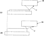
X axle prealignment sensor 38 is sensors of the edge portion of testing platform 16 for the approximate location of the X-direction of adjusting the inspection substrate P on the worktable 16.Shown in Fig. 5~8, X axle prealignment sensor 38 constitutes and comprises the light-emitting component (not shown) that sends inspection light C and accept and send and at the photo detector (not shown) of the inspection light C of the surface reflection of inspection substrate P from this light-emitting component.These light-emitting components and photo detector set into, light C is parallel with the edge portion of inspection substrate P in this inspection.This point is according to following reason.Shown in Fig. 8 (A), (B), when the edge portion quadrature that sets to inspection light C and inspection substrate P, cause squinting by the thickness of inspection substrate P.(A) of Fig. 8 is the example of the inspection substrate P that approaches, and (B) of Fig. 8 is the example of thick inspection substrate P.Compare with the thin inspection substrate P of Fig. 8 (A), under the situation of the thick inspection substrate P of Fig. 8 (B), inspection light C is near the position reflection of light-emitting component and detecting quickly than thin inspection substrate P.With respect to this, make inspection light C when parallel with the edge portion of inspection substrate P, irrelevant with the thickness of inspection substrate P.Therefore, with light-emitting component and photo detector set into, C is parallel with the edge portion of inspection substrate P for this inspection light.
Fig. 5, the Z axle straight-line motion mechanism 39 shown in 6 are to be used to support retrieval to make its device mobile on Z-direction with camera 40 etc.Z axle straight-line motion mechanism 39 is carried by the 39A of portion of Z axle travel mechanism, Z axle puts plate 39B and Z axle motor 39C constitutes.The 39A of portion of Z axle travel mechanism is used on Z-direction, supporting the Z axle slidably to carry the member of putting plate 39B.The 39A of portion of Z axle travel mechanism is made up of guide rail etc.The Z axle carries to be put plate 39B and is used to support the member of retrieval with camera 40 grades.The Z axle carries to be put plate 39B and comprises the carriage 39D with horizontally extending 2 arms, retrieval is installed with camera 40 etc. on this carriage 39D.Z axle motor 39C is used to that the Z axle is carried to put the motor that plate 39B moves on Z-direction.In Z axle motor 39C, comprise screw rod and travelling nut (all not shown), travelling nut is fixed in the Z axle and carries and put plate 39B, the Z axle is carried put plate 39B on Z-direction, to move.
Retrieval is to be used for retrieving the camera of the location of inspection substrate P with mark with big visual field with camera 40.Align cameras 41 is that the location that is used for discerning exactly by retrieving with camera 40 appointments makes the inspection substrate P camera of contraposition exactly with mark.Align cameras 41 is taken inspection substrate P with small field of view.Retrieval is supported on 2 arms of carriage 39D respectively with camera 40 and align cameras 41.Gauge head assembly 42 is to be used for contacting with the electrode electricity of the hookup E of inspection substrate P and the member checked.
The 2Z axle carries the portion of putting 28 and is used to make carry the device of putting in the X-direction of the inspection substrate P on the worktable 16 and roughly contraposition of Y direction, making inspection substrate P contraposition exactly afterwards, contact with electrode electricity on the inspection substrate P.This 2Z axle carries the portion of putting 28, and whole to carry the portion of putting 27 same with above-mentioned 1Z axle.As shown in Figure 9, carry in the portion of putting 28 at the 2Z axle, carry at the 1Z axle on the basis of the portion of putting 27 and also comprise Y axle prealignment sensor 43.This Y axle prealignment sensor 43 is sensors of the edge portion of testing platform 16 for the approximate location of the Y direction of adjusting the inspection substrate P on the worktable 16.Y axle prealignment sensor 43 constitutes with X axle prealignment sensor 38 and likewise comprises light-emitting component and photo detector.These light-emitting components and photo detector are adapted to, and C is parallel with the edge portion of inspection substrate P for this inspection light.Thus, X axle prealignment sensor 38 is adapted to Y axle prealignment sensor 43, and the inspection light C of the inspection light C of X axle prealignment sensor 38 and Y axle prealignment sensor 43 forms the position relation of quadrature.
The aligning guide 11 of the inspection substrate P that constitutes as described above moves as follows.Describe according to Figure 10~14.
At first, shown in figure 10, inspection substrate P carries and places X θ shaft-like work to carry the worktable 16 of putting platform 12, is carried by this X θ shaft-like work and puts platform 12 and be transplanted on YZ and be coupling to touch to carry and put platform 13 sides.At this moment, if inspection substrate P dislocation is then shown in figure 11, an edge portion that takes the lead in detecting inspection substrate P in 2 X axle prealignment sensors 38.Then, shown in figure 12, another X axle prealignment sensor 38 detects the edge portion of inspection substrate P.Based on the detection deviation of these 2 X axle prealignment sensors 38, utilize control part 45 that coordinate is enrolled in the inclination of inspection substrate P and calculate.Then, shown in figure 13, utilize control part 45 control X θ shaft-like works to carry the θ axle rotating mechanism of putting platform 12, make the tilt quantity of the above-mentioned inspection substrate P of worktable 16 rotations and proofread and correct.
Then, the 2Z axle carries the portion of putting 28 and utilizes Y axle straight-line motion mechanism 26 on Y direction, to move, and utilizes Y axle prealignment sensor 43 to detect the edge portion of inspection substrate P.
Thus, confirm X-direction and the position of Y direction and the angle of inspection substrate P of inspection substrate P, make inspection substrate P carry out roughly contraposition.
Then, utilize retrieval with camera 40, mark is used in the location of definite inspection substrate P with big visual field shooting inspection substrate P.Then, utilize align cameras 41, adjust the position of inspection substrate P with the location of small field of view shooting inspection substrate P with mark exactly.Then, the probe of gauge head assembly 42 is contacted with the electrode of hookup E and checks.
Through above operation,, also can carry out prealignment reliably even for large-scale inspection substrate P.
Even put platform 12 and YZ and be coupling to touch to carry and put platform 13 and make separately under the situation of member independently X θ shaft-like work being carried, also can proofread and correct the dislocation of inspection substrate P and carry out prealignment reliably in order to proofread and correct by control part 45.
Since YZ be coupling touch carry comprise in the Z axle straight-line motion mechanism 39 put platform 13 retrieval of taking inspection substrate P with mark with big visual field for the location of retrieving inspection substrate P with camera 40 and in order to locate inspection substrate P exactly with the align cameras 41 of small field of view shooting inspection substrate P; Therefore; X axle prealignment sensor 38 and Y axle prealignment sensor 43 mutually combine, and can make large-scale inspection substrate P contraposition at short notice easily and exactly.As a result, improved the inspection operation property of inspection substrate P.
By the light-emitting component that sends inspection light C with accept to send and constitute X axle prealignment sensor 38 and Y axle prealignment sensor 43 at the photo detector of the inspection light C of the surface reflection of above-mentioned inspection substrate from this light-emitting component; With above-mentioned light-emitting component and photo detector set into above-mentioned inspection light C parallel with the edge portion of inspection substrate P; Therefore, can detect the edge portion of inspection substrate P exactly.As a result, can make large-scale inspection substrate P contraposition at short notice easily and exactly, improve the inspection operation property of inspection substrate P.
In addition; Carry as the X θ shaft-like work of individual member and put platform 12 and YZ and be coupling and touch the calibration function of the dislocation of carrying when putting platform 13 and being provided with etc. because control part 45 has absorption; Therefore; Even X θ shaft-like work carries and puts platform 12 and YZ and be coupling to touch to carry and put platform 13 and misplace because of various situations, also can make large-scale inspection substrate P contraposition exactly.
The 2nd embodiment
Then, according to Figure 15 the 2nd embodiment of the present invention is described.
Because the unitary construction of the aligning guide 51 of this embodiment and the aligning guide 11 of above-mentioned the 1st embodiment are roughly the same, therefore, the Reference numeral identical to identical member mark omits its explanation.The aligning guide 51 of this embodiment has appended in the aligning guide 11 of the 1st embodiment that the 3Z axle carries the portion of putting 52 and the 4Z axle carries the portion of putting 53.
The 3Z axle carries the portion of putting 52 and carries X axle prealignment sensor 38 in each device of the portion of putting 27, retrieval with camera 40, the align cameras 41, the only extra gauge head assembly 42 that is formed with except the 1Z axle of above-mentioned Fig. 5, above-mentioned the 1st embodiment shown in 6.Carry the Z axle of the Z axle straight-line motion mechanism 39 put plate 37 and carry to put gauge head assembly 42 is installed on the plate 39B being installed on contact.This 3Z axle carries the portion of putting 52 and utilizes the Y axle straight-line motion mechanism 26 by control part 45 controls on Y direction, suitably to move, and the electrode of the hookup E of the probe of gauge head assembly 42 and inspection substrate P is aligned with each other.Then, utilize Z axle straight-line motion mechanism 39 that gauge head assembly 42 is moved up and down and probe is contacted with the electrode electricity of the hookup E of inspection substrate P.
The 4Z axle carries the portion of putting 53 and carries the same device of the portion of putting 52 with the 3Z axle.In this embodiment, append the 3Z axle and carry the portion of putting 52 and 4Z axle and carry the portion's of putting 53 these 2 devices and make 4 Z axles and carry the portion of putting.Make the reason that 4 Z axles carry the portion of putting and be, the hookup E on the inspection substrate P is adapted to 4 row.Promptly; In the inspection substrate P of this embodiment; Because hookup E is adapted to 4 row 4 row, therefore, with the 1Z axle carry the portion of putting 27,2Z axle carry the portion of putting 28,3Z axle carry the portion of putting 52 and 4Z axle carry the portion of putting 53 respectively alignment test circuit E row set; The probe of 4 gauge head assemblies 42 is contacted with 4 hookup E respectively, accomplish the test of 1 inspection substrate P with 4 contacts.
Specifically; Utilizing Y axle straight-line motion mechanism 26 to make the 1Z axle carry the portion of putting 27 and 2Z axle carries the portion of putting 28 and on Y direction, suitably moves; Detect the edge portion of inspection substrate P by X axle prealignment sensor 38 and Y axle prealignment sensor 43; Specify X-direction and the position of Y direction and the angle of inspection substrate P of inspection substrate P, make roughly contraposition of inspection substrate P.Then, utilize retrieval to use mark, utilize align cameras 41 to adjust the position of inspection substrate P exactly with the location of camera 40 retrieval inspection substrate P.
Then; Control part 45 calculates the position of each the hookup E on the inspection substrate P based on the inspection substrate P that locatees exactly; Control Y axle straight-line motion mechanism 26 makes the 3Z axle carry the portion of putting 52 and 4Z axle and carries the portion of putting 53 and carry that the portion of putting 27 and 2Z axle carry that the portion of putting 28 together moves and each hookup E of aiming at the 1st row with the 1Z axle respectively.Then, utilize Z axle straight-line motion mechanism 39 to make each probe of gauge head assembly 42 be contacted with the electrode of each hookup E and check.While utilizing X θ shaft-like work to carry to put platform 12 to make inspection substrate P on X-direction, move, make the electrode of each probe and the 2nd~4 capable each hookup E of gauge head assembly 42 to contact and checking.Then, accomplish the test of 1 inspection substrate P with these 4 times contacts.
Thus, play and the same effect of above-mentioned the 1st embodiment, and, check abreast owing to utilize 4 Z axles to carry the portion of putting, therefore can seek to check efficiency of operationization.Particularly in large-scale inspection substrate P; If the Z axle carries the negligible amounts of the portion of putting, then this Z axle amount of movement of carrying the portion of putting is more, inspection operation spended time; But check abreast through utilize 4 Z axles to carry the portion of putting in this wise as this embodiment, can seek to check efficiency of operationization.
Variation
In above-mentioned the 1st embodiment, utilize this Y axle straight-line motion mechanism can be on Y direction movably the Z axle of supporting carry the portion of putting and be set to the 1Z axle and carry the portion of putting 27 and 2Z axle and carry the portion of putting 28 these 2, but also can be provided with more than 3., be not defined as its edge portion and be maintained size accurately yet when being large-scale at inspection substrate P, therefore, detect the edge portion of inspection substrate P in many places and on coordinate, confirm its each position.At this moment, under the situation that they misplace mutually, judge in its scope that whether is in error.Like this, if in error range, then can ignore, if exceed error range, then according to the mean value specified coordinate of each point.
In above-mentioned the 2nd embodiment; Append 2 Z axles with respect to the 1st embodiment and carry the portion of putting 52,53 and make 4 Z axles and carry portion's of putting (the 1st~the 4Z axle carries the portion of putting 27,28,52,53), carry the portion of putting and make that 3 Z axles carry the portion of putting or 5 above Z axles carry the portion of putting but also can append 1 or 3 above Z axles with respect to the 1st embodiment.Set the number that is provided with that the Z axle carries the portion of putting according to all conditions such as the size of inspection substrate P, the number of hookup E.
In addition, carry under the situation of the portion of putting being provided with a plurality of Z axles, 43 expectations of Y axle prealignment sensor are arranged on the Z axle that a plurality of Z axles carry the end in the portion of putting and carry the portion of putting, and carry the portion of putting but X axle prealignment sensor 38 also can be arranged at each Z axle.As long as because can be, therefore, also can be arranged on 2 Z axles that separate to a certain degree that a plurality of Z axles carry in the portion of putting and carry the portion of putting in to a certain degree the edge portion of the 2 position probing inspection substrate P of place separately.In addition, also can carry X axle prealignment sensor 38 is set in the portion of putting, suitably select separately to a certain degree 2 Z axles to carry the X axle prealignment sensor 38 of the portion of putting and detect the edge portion of inspection substrate P at all Z axles.
Thus, also can play and same effect, the effect of the above-mentioned the 1st and the 2nd embodiment.