JP5154917B2 - プロービング装置で焦点を合わせて多平面画像を取得する装置と方法 - Google Patents
プロービング装置で焦点を合わせて多平面画像を取得する装置と方法 Download PDFInfo
- Publication number
- JP5154917B2 JP5154917B2 JP2007337424A JP2007337424A JP5154917B2 JP 5154917 B2 JP5154917 B2 JP 5154917B2 JP 2007337424 A JP2007337424 A JP 2007337424A JP 2007337424 A JP2007337424 A JP 2007337424A JP 5154917 B2 JP5154917 B2 JP 5154917B2
- Authority
- JP
- Japan
- Prior art keywords
- objective lens
- microscope
- image
- focusing
- probe
- Prior art date
- Legal status (The legal status is an assumption and is not a legal conclusion. Google has not performed a legal analysis and makes no representation as to the accuracy of the status listed.)
- Expired - Fee Related
Links
Images


Classifications
-
- G—PHYSICS
- G02—OPTICS
- G02B—OPTICAL ELEMENTS, SYSTEMS OR APPARATUS
- G02B21/00—Microscopes
- G02B21/36—Microscopes arranged for photographic purposes or projection purposes or digital imaging or video purposes including associated control and data processing arrangements
- G02B21/365—Control or image processing arrangements for digital or video microscopes
-
- G—PHYSICS
- G02—OPTICS
- G02B—OPTICAL ELEMENTS, SYSTEMS OR APPARATUS
- G02B21/00—Microscopes
- G02B21/24—Base structure
- G02B21/241—Devices for focusing
- G02B21/244—Devices for focusing using image analysis techniques
-
- G—PHYSICS
- G02—OPTICS
- G02B—OPTICAL ELEMENTS, SYSTEMS OR APPARATUS
- G02B21/00—Microscopes
- G02B21/24—Base structure
- G02B21/26—Stages; Adjusting means therefor
-
- G—PHYSICS
- G02—OPTICS
- G02B—OPTICAL ELEMENTS, SYSTEMS OR APPARATUS
- G02B21/00—Microscopes
- G02B21/32—Micromanipulators structurally combined with microscopes
-
- G—PHYSICS
- G02—OPTICS
- G02B—OPTICAL ELEMENTS, SYSTEMS OR APPARATUS
- G02B21/00—Microscopes
- G02B21/06—Means for illuminating specimens
Landscapes
- Physics & Mathematics (AREA)
- Chemical & Material Sciences (AREA)
- Analytical Chemistry (AREA)
- General Physics & Mathematics (AREA)
- Optics & Photonics (AREA)
- Engineering & Computer Science (AREA)
- Computer Vision & Pattern Recognition (AREA)
- Multimedia (AREA)
- Testing Or Measuring Of Semiconductors Or The Like (AREA)
- Microscoopes, Condenser (AREA)
- Tests Of Electronic Circuits (AREA)
Description
2 X−Y移動ステージ
3 ハウジング
4 固定装置
5 検査対象物
6 探針
7 探針ホルダ
8 探針ホルダプレート
9 開口
10 検査対象物の表面
11 画像取得装置
12 顕微鏡
13 照明装置
14 対物レンズ
15 ビデオカメラ
16 画像評価ユニット
17 プローブカード
18 プローブカード探針
19 プローブカードアダプタ
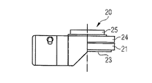
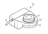
20 顕微鏡対物レンズ焦点合わせシステム
21 下側部分
22 接続線
23 雌ねじ
24 上側部分
25 ねじ付き軸
26 対物レンズホルダ
27 ボンディングパッド
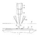
28 第1焦点面
29 探針の尖端
30 第2焦点面
31 第1位置
32 焦点
33 第2位置
Claims (15)
- プロービング装置(1)で焦点を合わせて多平面画像を取得するための装置であって、
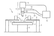
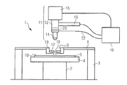
このプロービング装置(1)が、移動装置(2)と、この移動装置(2)上に配置された検査対象物(5)用の固定装置(4)と、この検査対象物(5)に接触可能な探針(6;18)と、前記探針(6;18)用の保持装置(7;17)と、前記固定装置(4)の上方に配置された固定プレート(8)とを有し、前記保持装置(7;17)が、この固定プレート(8)上に固定可能であり、この固定プレート(8)が、前記検査対象物(5)の表面を見ることができるように開放している観察開口(9)を有し、
前記プロービング装置(1)が、前記観察開口(9)の上方に配置された画像取得装置(11)を有し、この画像取得装置(11)が、対物レンズ(14)と対物レンズ保持部(26)とを有する顕微鏡(12)を備え、且つ、この画像取得装置(11)が、前記検査対象物(5)の表面(10)に向けられた光ビームを発生可能な照明装置(13)を備える、当該装置において、
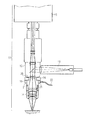
前記対物レンズ(14)が、前記顕微鏡(12)の垂直調節駆動装置に左右されずに、前記検査対象物(5)の前記表面(10)上の第1焦点面(30)内と探針尖端(29)の高さにある第2焦点面(30)内とに、前記対物レンズ(14)を焦点合わせ可能な顕微鏡対物レンズ焦点合わせシステム(20)を有すること、及び
前記顕微鏡対物レンズ焦点合わせシステム(20)が、前記対物レンズ保持部(26)と前記対物レンズ(14)との間に配置されている、ことを特徴とする装置。 - 前記顕微鏡対物レンズ焦点合わせシステム(20)は、電気的に調節可能に構成されていて且つこの顕微鏡対物レンズ焦点合わせシステム(20)の移動を制御する制御装置に接続されている、ことを特徴とする請求項1に記載の装置。
- 前記顕微鏡対物レンズ焦点合わせシステム(20)は、圧電式駆動装置を有する、ことを特徴とする請求項2に記載の装置。
- 前記顕微鏡対物レンズ焦点合わせシステム(20)は、対物レンズねじにねじ込み可能である顕微鏡側のねじ付き軸(25)と、前記対物レンズ(14)を保持するための雌ねじ(23)を有すること、及び、前記ねじ付き軸(25)と前記雌ねじ(23)とが、変位増幅式圧電式リニアアクチュエータによって軸方向に相対移動可能である、ことを特徴とする請求項1〜3のいずれか1項に記載の装置。
- 前記顕微鏡(12)は、共焦点顕微鏡として構成されている、ことを特徴とする請求項1〜4のいずれか1項に記載の装置。
- 前記画像取得装置(11)は、画像評価ユニット(16)に接続されている、ことを特徴とする請求項1〜5のいずれか1項に記載の装置。
- 前記画像評価ユニット(16)は、制御装置を有する、ことを特徴とする請求項6に記載の装置。
- 前記画像取得装置(11)は、ビデオカメラ(15)を有する、ことを特徴とする請求項1〜6のいずれか1項に記載の装置。
- プロービング装置(1)で焦点を合わせて多平面画像を取得するための方法であって、
検査対象物(5)の表面(10)から離隔された複数の探針(6;18)の複数の尖端(29)に対してこの検査対象物(5)を側面に沿って位置決めするため、顕微鏡(12)が、最初の時点に検査対象物(5)の表面(10)上に焦点合わせされ、次の第2の時点に当該両探針(6;18)の平面(30)上に焦点合わせされる、当該方法において、
顕微鏡対物レンズ焦点合わせシステム(20)が、対物レンズ保持部(26)と対物レンズ(14)との間に配置されていることによって、この対物レンズ(14)が、前記顕微鏡(12)の高さ調節に関係なく、異なる時点に両焦点面(28;30)上に焦点合わせされ、前記対物レンズ(14)の適当な焦点合わせ調節が、位置決め中に複数回変更される、ことを特徴とする方法。 - 複数の前記焦点合わせ調節は、残像周波数よりも高い周波数で変更される、ことを特徴とする請求項9に記載の方法。
- 複数の前記焦点合わせ調節の変更は、同じ時間間隔で実施される、ことを特徴とする請求項9または10に記載の方法。
- 前記顕微鏡(12)で撮影される画像が、ビデオカメラ(15)によって記録され、ディスプレイ上に表示される、ことを特徴とする請求項9又は10に記載の方法。
- 前記ビデオカメラ(15)によって記録された画像は、画像評価ユニット(16)に供給され、異なる焦点合わせ調節で撮影された連続する少なくとも2つの画像が記憶され、表示装置に重ねて投影されて表示される、ことを特徴とする請求項12に記載の方法。
- 前記検査対象物(5)の複数の画像がそれぞれ、色彩の異なる照明光で撮影され、引き続き前記探針(6;18)の尖端(29)の1つの画像が撮影され、1つの画像が、前記検査対象物(5)の当該複数の画像から合成され、前記探針(6;18)の前記尖端(29)の前記1つの画像が、前記1つの画像中に投影されるように、前記焦点合わせ調節の変更が実施される、ことを特徴とする請求項9〜13のいずれか1項に記載の方法。
- 別の照明色で実施される画像撮影ごとに、当該照明色のために鮮明さを最適化した焦点合わせ調節が、前記対物レンズ(14)に対して実施される、ことを特徴とする請求項14に記載の方法。
Applications Claiming Priority (4)
| Application Number | Priority Date | Filing Date | Title |
|---|---|---|---|
| DE102006062297 | 2006-12-27 | ||
| DE102006062297.9 | 2006-12-27 | ||
| DE102007002097 | 2007-01-09 | ||
| DE102007002097.1 | 2007-01-09 |
Publications (2)
| Publication Number | Publication Date |
|---|---|
| JP2008166806A JP2008166806A (ja) | 2008-07-17 |
| JP5154917B2 true JP5154917B2 (ja) | 2013-02-27 |
Family
ID=39695740
Family Applications (1)
| Application Number | Title | Priority Date | Filing Date |
|---|---|---|---|
| JP2007337424A Expired - Fee Related JP5154917B2 (ja) | 2006-12-27 | 2007-12-27 | プロービング装置で焦点を合わせて多平面画像を取得する装置と方法 |
Country Status (2)
| Country | Link |
|---|---|
| US (2) | US20080212078A1 (ja) |
| JP (1) | JP5154917B2 (ja) |
Families Citing this family (13)
| Publication number | Priority date | Publication date | Assignee | Title |
|---|---|---|---|---|
| JP2008167447A (ja) * | 2006-12-27 | 2008-07-17 | Suss Microtec Test Systems Gmbh | プローバで画像を記録するための装置および方法 |
| US8284246B2 (en) * | 2008-01-18 | 2012-10-09 | Olympus Corporation | Microscope system, control method used for microscope system, and recording medium for reproducing a microscope state based on microscope operation history and a microscope operation item |
| AT505671B1 (de) * | 2008-05-13 | 2009-03-15 | Evk Di Kerschhaggl Gmbh | Verfahren zum optischen detektieren von bewegten objekten |
| US8253784B2 (en) * | 2008-11-13 | 2012-08-28 | Honeywell International Inc. | Image capturing device assembly for use with test probe |
| JP4724756B2 (ja) * | 2009-01-07 | 2011-07-13 | 日置電機株式会社 | 基板検査用カメラのための照明装置を備える基板検査装置 |
| DE102009059274B4 (de) * | 2009-12-22 | 2012-07-19 | Max-Joseph Kraus | Verfahren zur Messung der Dynamik der Änderungen von Blutplättchen |
| US9110131B2 (en) | 2010-04-13 | 2015-08-18 | Cascade Microtech, Inc. | Method and device for contacting a row of contact areas with probe tips |
| EP2955947B1 (en) * | 2014-06-12 | 2019-07-31 | Uros Technology S.à r.l. | Processing of preferred roaming lists |
| US10785625B2 (en) * | 2016-02-17 | 2020-09-22 | Wistron Aidge Corporation | Internet of Things (IOT) companion device |
| JP6781120B2 (ja) * | 2017-08-18 | 2020-11-04 | 株式会社日本マイクロニクス | 検査装置 |
| US10698025B2 (en) * | 2018-07-20 | 2020-06-30 | Formfactor Beaverton, Inc. | Probe systems and methods that utilize a flow-regulating structure for improved collection of an optical image of a device under test |
| DE102018121911A1 (de) * | 2018-09-07 | 2020-03-12 | Formfactor Gmbh | Verfahren zur Positionierung von Testsubstrat, Sonden und Inspektionseinheit relativ zueinander und Prober zu dessen Ausführung |
| US12203959B2 (en) | 2022-11-18 | 2025-01-21 | Formfactor, Inc. | Methods of establishing contact between a probe tip of a probe system and a device under test, probe systems that perform the methods, and storage media that directs probe systems to perform the methods |
Family Cites Families (14)
| Publication number | Priority date | Publication date | Assignee | Title |
|---|---|---|---|---|
| JPS5917260A (ja) * | 1982-07-20 | 1984-01-28 | Mitsubishi Electric Corp | 半導体ウエハの試験方法 |
| JPS63204153A (ja) * | 1987-02-19 | 1988-08-23 | Tokyo Electron Ltd | プロ−ブ装置 |
| EP0606736A3 (en) * | 1992-12-11 | 1995-03-15 | Nippon Kogaku Kk | A multi-LED color scanning device and associated color image scanning method. |
| US5394100A (en) * | 1993-05-06 | 1995-02-28 | Karl Suss America, Incorporated | Probe system with automatic control of contact pressure and probe alignment |
| US5880465A (en) * | 1996-05-31 | 1999-03-09 | Kovex Corporation | Scanning confocal microscope with oscillating objective lens |
| US6002426A (en) * | 1997-07-02 | 1999-12-14 | Cerprobe Corporation | Inverted alignment station and method for calibrating needles of probe card for probe testing of integrated circuits |
| US6096567A (en) * | 1997-12-01 | 2000-08-01 | Electroglas, Inc. | Method and apparatus for direct probe sensing |
| US6590612B1 (en) * | 1999-03-18 | 2003-07-08 | Cellavision Ab | Optical system and method for composing color images from chromatically non-compensated optics |
| JP3544892B2 (ja) * | 1999-05-12 | 2004-07-21 | 株式会社東京精密 | 外観検査方法及び装置 |
| JP2004022871A (ja) * | 2002-06-18 | 2004-01-22 | Nec Kansai Ltd | マニピュレータ型プローブ装置およびそのプローブピンの位置調整方法 |
| US20040102903A1 (en) * | 2002-11-27 | 2004-05-27 | Graessle Josef A. | Biological growth plate scanner |
| DE102004034970A1 (de) * | 2004-07-16 | 2006-02-02 | Carl Zeiss Jena Gmbh | Lichtrastermikroskop und Verwendung |
| US7656172B2 (en) * | 2005-01-31 | 2010-02-02 | Cascade Microtech, Inc. | System for testing semiconductors |
| JP2008167447A (ja) * | 2006-12-27 | 2008-07-17 | Suss Microtec Test Systems Gmbh | プローバで画像を記録するための装置および方法 |
-
2007
- 2007-12-27 US US11/964,744 patent/US20080212078A1/en not_active Abandoned
- 2007-12-27 JP JP2007337424A patent/JP5154917B2/ja not_active Expired - Fee Related
-
2010
- 2010-07-30 US US12/847,723 patent/US8072586B2/en not_active Expired - Fee Related
Also Published As
| Publication number | Publication date |
|---|---|
| US20080212078A1 (en) | 2008-09-04 |
| JP2008166806A (ja) | 2008-07-17 |
| US20110013011A1 (en) | 2011-01-20 |
| US8072586B2 (en) | 2011-12-06 |
Similar Documents
| Publication | Publication Date | Title |
|---|---|---|
| JP5154917B2 (ja) | プロービング装置で焦点を合わせて多平面画像を取得する装置と方法 | |
| US20080158664A1 (en) | Arrangement and method for image acquisition on a prober | |
| JP5325522B2 (ja) | 複合型観察装置 | |
| JP6009862B2 (ja) | 走査型プローブ顕微鏡 | |
| JP5863357B2 (ja) | 拡大観察装置、並びに、拡大観察装置の画像表示方法及び検鏡法切換方法 | |
| US11681133B2 (en) | System and method for macroscopic and microscopic imaging ex-vivo tissue | |
| JP4567594B2 (ja) | 顕微鏡、試料観察方法、及び半導体検査方法 | |
| CN101019058A (zh) | 带焦点位置控制机构的观察装置 | |
| JP2010080144A (ja) | 複合型顕微鏡装置及び試料観察方法 | |
| JPH10339845A (ja) | モニタ観察型顕微鏡 | |
| CN111989608A (zh) | 对样品进行显微观察以呈现具有扩展景深的图像或三维图像的显微镜和方法 | |
| JP6590429B1 (ja) | 共焦点顕微鏡、及びその撮像方法 | |
| JP2007140183A (ja) | 共焦点走査型顕微鏡装置 | |
| JP2003315238A (ja) | 測定位置合わせ方法、カンチレバ及び走査形プローブ顕微鏡 | |
| JP2019144456A (ja) | 観察装置 | |
| JP3125124U (ja) | 赤外顕微鏡 | |
| JP6255305B2 (ja) | 光学顕微装置 | |
| JP4963567B2 (ja) | 微小高さ測定装置 | |
| JP6971770B2 (ja) | 拡大観察装置 | |
| JP3126047B2 (ja) | 走査型プローブ顕微鏡 | |
| CN113885187A (zh) | 数字显微镜和显微套件 | |
| KR102715080B1 (ko) | 현미경용 얼라인 장치 | |
| JP2024154082A (ja) | レンズユニットおよび拡大観察装置 | |
| JP2008046362A (ja) | 光学装置 | |
| JP2008299210A (ja) | 干渉対物レンズと、その干渉対物レンズを備える干渉顕微鏡装置 |
Legal Events
| Date | Code | Title | Description |
|---|---|---|---|
| A521 | Request for written amendment filed |
Free format text: JAPANESE INTERMEDIATE CODE: A821 Effective date: 20080613 |
|
| A521 | Request for written amendment filed |
Free format text: JAPANESE INTERMEDIATE CODE: A523 Effective date: 20080613 |
|
| A621 | Written request for application examination |
Free format text: JAPANESE INTERMEDIATE CODE: A621 Effective date: 20100317 |
|
| RD04 | Notification of resignation of power of attorney |
Free format text: JAPANESE INTERMEDIATE CODE: A7424 Effective date: 20100526 |
|
| A977 | Report on retrieval |
Free format text: JAPANESE INTERMEDIATE CODE: A971007 Effective date: 20120531 |
|
| A131 | Notification of reasons for refusal |
Free format text: JAPANESE INTERMEDIATE CODE: A131 Effective date: 20120619 |
|
| A521 | Request for written amendment filed |
Free format text: JAPANESE INTERMEDIATE CODE: A523 Effective date: 20120906 |
|
| TRDD | Decision of grant or rejection written | ||
| A01 | Written decision to grant a patent or to grant a registration (utility model) |
Free format text: JAPANESE INTERMEDIATE CODE: A01 Effective date: 20121127 |
|
| A61 | First payment of annual fees (during grant procedure) |
Free format text: JAPANESE INTERMEDIATE CODE: A61 Effective date: 20121206 |
|
| FPAY | Renewal fee payment (event date is renewal date of database) |
Free format text: PAYMENT UNTIL: 20151214 Year of fee payment: 3 |
|
| R150 | Certificate of patent or registration of utility model |
Ref document number: 5154917 Country of ref document: JP Free format text: JAPANESE INTERMEDIATE CODE: R150 Free format text: JAPANESE INTERMEDIATE CODE: R150 |
|
| R250 | Receipt of annual fees |
Free format text: JAPANESE INTERMEDIATE CODE: R250 |
|
| R250 | Receipt of annual fees |
Free format text: JAPANESE INTERMEDIATE CODE: R250 |
|
| R250 | Receipt of annual fees |
Free format text: JAPANESE INTERMEDIATE CODE: R250 |
|
| R250 | Receipt of annual fees |
Free format text: JAPANESE INTERMEDIATE CODE: R250 |
|
| R250 | Receipt of annual fees |
Free format text: JAPANESE INTERMEDIATE CODE: R250 |
|
| R250 | Receipt of annual fees |
Free format text: JAPANESE INTERMEDIATE CODE: R250 |
|
| R250 | Receipt of annual fees |
Free format text: JAPANESE INTERMEDIATE CODE: R250 |
|
| R250 | Receipt of annual fees |
Free format text: JAPANESE INTERMEDIATE CODE: R250 |
|
| LAPS | Cancellation because of no payment of annual fees |