JP5154917B2 - Apparatus and method for acquiring a multi-plane image by focusing with a probing apparatus - Google Patents
Apparatus and method for acquiring a multi-plane image by focusing with a probing apparatus Download PDFInfo
- Publication number
- JP5154917B2 JP5154917B2 JP2007337424A JP2007337424A JP5154917B2 JP 5154917 B2 JP5154917 B2 JP 5154917B2 JP 2007337424 A JP2007337424 A JP 2007337424A JP 2007337424 A JP2007337424 A JP 2007337424A JP 5154917 B2 JP5154917 B2 JP 5154917B2
- Authority
- JP
- Japan
- Prior art keywords
- objective lens
- microscope
- image
- focusing
- probe
- Prior art date
- Legal status (The legal status is an assumption and is not a legal conclusion. Google has not performed a legal analysis and makes no representation as to the accuracy of the status listed.)
- Expired - Fee Related
Links
Images


Classifications
-
- G—PHYSICS
- G02—OPTICS
- G02B—OPTICAL ELEMENTS, SYSTEMS OR APPARATUS
- G02B21/00—Microscopes
- G02B21/36—Microscopes arranged for photographic purposes or projection purposes or digital imaging or video purposes including associated control and data processing arrangements
- G02B21/365—Control or image processing arrangements for digital or video microscopes
-
- G—PHYSICS
- G02—OPTICS
- G02B—OPTICAL ELEMENTS, SYSTEMS OR APPARATUS
- G02B21/00—Microscopes
- G02B21/24—Base structure
- G02B21/241—Devices for focusing
- G02B21/244—Devices for focusing using image analysis techniques
-
- G—PHYSICS
- G02—OPTICS
- G02B—OPTICAL ELEMENTS, SYSTEMS OR APPARATUS
- G02B21/00—Microscopes
- G02B21/24—Base structure
- G02B21/26—Stages; Adjusting means therefor
-
- G—PHYSICS
- G02—OPTICS
- G02B—OPTICAL ELEMENTS, SYSTEMS OR APPARATUS
- G02B21/00—Microscopes
- G02B21/32—Micromanipulators structurally combined with microscopes
-
- G—PHYSICS
- G02—OPTICS
- G02B—OPTICAL ELEMENTS, SYSTEMS OR APPARATUS
- G02B21/00—Microscopes
- G02B21/06—Means for illuminating specimens
Landscapes
- Physics & Mathematics (AREA)
- Chemical & Material Sciences (AREA)
- Analytical Chemistry (AREA)
- General Physics & Mathematics (AREA)
- Optics & Photonics (AREA)
- Engineering & Computer Science (AREA)
- Computer Vision & Pattern Recognition (AREA)
- Multimedia (AREA)
- Testing Or Measuring Of Semiconductors Or The Like (AREA)
- Microscoopes, Condenser (AREA)
- Tests Of Electronic Circuits (AREA)
Description
本発明は、移動装置と、この移動装置上に配置された検査対象物用固定装置と、検査対象物に接触可能な探針と、探針用保持装置と、固定装置の上方に配置された、保持装置を固定可能な固定プレートとを具備し、この固定プレートが検査対象物の表面を見ることができるように開放した観察開口を有し、さらに観察開口の上方に配置された画像取得装置を具備し、この画像取得装置が対物レンズと対物レンズ保持部を有する顕微鏡を含み、画像取得装置が検査対象物の表面に向いた光ビームを発生可能な照明装置を備えている、プロービング装置で焦点を合わせて多平面画像を取得するための装置に関する。 The present invention is arranged above a moving device, a fixing device for an inspection object disposed on the moving device, a probe that can contact the inspection object, a holding device for the probe, and the fixing device. And an image acquisition device having an observation opening that is open so that the surface of the object to be inspected can be seen, and further disposed above the observation opening. A probing apparatus, the image acquisition apparatus including a microscope having an objective lens and an objective lens holding unit, and the image acquisition apparatus includes an illumination device capable of generating a light beam directed toward the surface of the inspection object. The present invention relates to an apparatus for acquiring a multi-plane image in focus.
本発明はさらに、検査対象物の表面から離隔された複数の探針の複数の尖端までこの検査対象物を側面に沿って位置決めするため、顕微鏡が、最初の時点に検査対象物の表面上に焦点合わせされ、次の時点に当該両探針の平面上に焦点合わせされる、プロービング装置で焦点を合わせて多平面画像を取得するための方法に関する。 The present invention further positions the inspection object along the side to a plurality of tips of a plurality of probes spaced from the surface of the inspection object, so that the microscope is initially on the surface of the inspection object. is focused, and focused on the plane of the two probes to the next point relates to a method for obtaining a multi-planar image focused probing device.
細胞、花粉粒等のような顕微鏡でしか見えぬほど小さな物体の三次元画像を生成するために、いわゆる共焦点顕微鏡が知られている。共焦点顕微鏡は、物体の仮想光学断面を生成可能な光学顕微鏡の変形である。この断面画像は続いて、適当なソフトウェアによって三次元表示のために合成される。 A so-called confocal microscope is known for generating a three-dimensional image of an object that can only be seen with a microscope, such as cells, pollen grains, and the like. A confocal microscope is a modification of an optical microscope that can generate a virtual optical section of an object. This cross-sectional image is subsequently synthesized for 3D display by suitable software.
この共焦点顕微鏡の場合、光は絞り板を通ってビームスプリットミラーと対物レンズを経てプレパラートに達する。放出された光は対物レンズによって捕らえられ、絞り板の開口に焦点を合わせられる。この開口の背後に検出器が設けられている。絞り板は、対物レンズに調節された焦点面よりも高い位置または低い位置にある層によってビームを表示しないで隠す働きをする。それによって、焦点面内でプレパラートを通る断面に一致する画像が得られる。共焦点顕微鏡によって三次元結像を得るために、この焦点面の画像が記憶され、続いて対物レンズの焦点が第1焦点面に対して間隔を有する他の焦点面内にセットされる。その後で再び、この他の焦点面内でプレパラートを通る断面に一致する画像が生成されて記憶される。この過程を複数回繰り返した後で、適当なソフトウェアを用いて、異なる焦点面の個々の画像から、プレパラートの三次元結像が生成される。 In the case of this confocal microscope, the light passes through the diaphragm plate, reaches the preparation through the beam split mirror and the objective lens. The emitted light is captured by the objective lens and focused on the aperture of the aperture plate. A detector is provided behind the opening. The diaphragm plate serves to hide the beam without displaying it by a layer located higher or lower than the focal plane adjusted to the objective lens. Thereby, an image is obtained that matches the cross-section passing through the preparation in the focal plane. In order to obtain a three-dimensional image by the confocal microscope, an image of this focal plane is stored, and then the focal point of the objective lens is set in another focal plane spaced from the first focal plane. Thereafter, again, an image matching the cross-section passing through the preparation in this other focal plane is generated and stored. After repeating this process multiple times, a suitable three-dimensional image of the slide is generated from individual images at different focal planes using appropriate software.
共焦点顕微鏡の対物レンズの焦点を調節するために、顕微鏡対物レンズ焦点合わせシステムを高速作動のコンパクトな調節ユニットとして使用することが知られている。この調節ユニットはほとんどの顕微鏡に組込み可能である。そのために、調節ユニットはリボルバと対物レンズの間にねじ止めされる。このような顕微鏡対物レンズ焦点合わせシステムはリボルバ側にねじ付き軸を備え、このねじ付き軸は顕微鏡リボルバの対物レンズねじに螺合可能である。対物レンズ自体は顕微鏡対物レンズ焦点合わせシステムの雌ねじにねじ込まれる。 In order to adjust the focus of the objective lens of a confocal microscope, it is known to use the microscope objective focusing system as a fast operating compact adjustment unit. This adjustment unit can be integrated into most microscopes. For this purpose, the adjusting unit is screwed between the revolver and the objective lens. Such a microscope objective focusing system has a threaded shaft on the revolver side, which can be screwed onto the microscope revolver objective lens screw. The objective lens itself is screwed into the internal thread of the microscope objective focusing system.
ねじ付き軸と雌ねじは、変位増幅式圧電式リニアアクチュエータによって相対的に軸方向に移動可能である。それによって、圧電式リニアアクチュエータに異なる電圧を掛けると、対物レンズとリボルバヘッドの間隔、ひいては焦点を電気的に変更することができる。従って、共焦点顕微鏡による走査時の適当な焦点面の選択は顕微鏡対物レンズ焦点合わせシステムの電圧を変更することによって行うことができる。 The threaded shaft and the female thread are relatively movable in the axial direction by a displacement amplification type piezoelectric linear actuator. Accordingly, when a different voltage is applied to the piezoelectric linear actuator, the distance between the objective lens and the revolver head, and hence the focal point, can be electrically changed. Accordingly, selection of an appropriate focal plane during scanning with a confocal microscope can be made by changing the voltage of the microscope objective lens focusing system.
この共焦点顕微鏡の場合、検査すべき物体の照明はレーザビームによって行われる。その際、レーザビームは物体全体を照明するように拡げられる。物体を完全に照明する他の方法では、レーザビームが拡げられないで、一種のスキャナモードで時間と共に動かされ、物体が走査されるレーザビームによって照明される。 In the case of this confocal microscope, the object to be examined is illuminated by a laser beam. At that time, the laser beam is expanded to illuminate the entire object. In another way of completely illuminating the object, the laser beam is not expanded but moved over time in a kind of scanner mode and the object is illuminated by the scanned laser beam.
さらに、小さな強度で多色結像を可能にする白色光共焦点顕微鏡が知られている。 Furthermore, white light confocal microscopes that allow multicolor imaging with low intensity are known.
構成部品、特に半導体構成部品の技術的機能および物理パラメータの影響を検査するために、いわゆるプロービング装置が知られている。プロービング装置は一般的に、位置補正のために小さな回転運動を行うことができる移動装置、例えばX−Y移動ステージを備えている。この移動装置上には、固定装置、いわゆるチャックが配置されている。固定装置の上方には、侵入兼観察開口を有する固定プレートが設けられている。この固定プレート上には、探針のための保持装置を例えば吸着ホルダによって固定することができる。それによって、探針は侵入兼観察開口を通過し、検査すべき物体の適当な個所に電気的に接触することができ、従って検査すべき物体の電気的な特性を正確に測定することができる。 In order to inspect the influence of the technical functions and physical parameters of components, in particular semiconductor components, so-called probing devices are known. The probing device generally includes a moving device capable of performing a small rotational movement for position correction, for example, an XY moving stage. A fixing device, a so-called chuck, is disposed on the moving device. Above the fixing device, a fixing plate having an intrusion and observation opening is provided. On the fixed plate, a holding device for the probe can be fixed by, for example, a suction holder. Thereby, the probe can pass through the intrusion and observation aperture and make electrical contact with the appropriate part of the object to be inspected, so that the electrical properties of the object to be inspected can be measured accurately. .
いわゆるプローブカードを備えた解決策も知られている。この解決策の場合、探針がプローブカード針としてプローブカードに動かぬように固定され、そしてプローブカードが固定プレートに固定されている。 Solutions with so-called probe cards are also known. In this solution, the probe is fixed as a probe card needle so as not to move to the probe card, and the probe card is fixed to the fixing plate.
検査対象物は基本的には、探針の尖端と相対的に位置決めすべきである。そのために通常は、移動装置を垂直方向に移動させて、検査対象物を探針から分離する。探針尖端と検査対象物の間の間隔は通常200〜250μmである。そして、移動装置は固定装置ひいては検査対象物を移動させ、他の検査対象物または検査対象物の他の部分が探針尖端の下方に位置するようにする。その後で、さらに垂直移動させることにより、検査対象物と探針尖端が再び接触する。この位置決め過程は通常、画像取得装置によってチェックされる。この画像取得装置は顕微鏡を含み、通常はさらにビデオカメラを備えている。画像取得装置、すなわち顕微鏡の対物レンズは観察開口の上方に配置されている。画像取得装置によって検査対象物の表面が撮影され、画像評価装置に供給される。画像評価ユニットでは、適当な分析プログラムによって移動装置を正確に次のように制御することができる。すなわち、探針尖端を検査対象物上の接触部のすぐ上に配置し、測定過程を開始できるように制御することができる。 The inspection object should basically be positioned relative to the tip of the probe. For this purpose, the moving object is usually moved in the vertical direction to separate the inspection object from the probe. The distance between the probe tip and the inspection object is usually 200 to 250 μm. Then, the moving device moves the fixing device, and thus the inspection object, so that the other inspection object or other part of the inspection object is positioned below the tip of the probe. Thereafter, the object to be inspected and the tip of the probe come into contact again by further vertical movement. This positioning process is usually checked by an image acquisition device. This image acquisition device includes a microscope and usually further includes a video camera. The objective lens of the image acquisition device, that is, the microscope is disposed above the observation aperture. The surface of the inspection object is photographed by the image acquisition device and supplied to the image evaluation device. In the image evaluation unit, the mobile device can be accurately controlled as follows by an appropriate analysis program. That is, it is possible to control the probe tip so that the measurement process can be started by placing the probe tip just above the contact portion on the inspection object.
手動式プロービング装置の場合には、ビデオカメラによって生成される画像を拡大して示すディスプレイを介してあるいは顕微鏡の接眼レンズで直接的に、観察が操作人によって行われる。そして、操作人は表示された位置に相応して位置決めおよび接触を制御する。 In the case of a manual probing device, observation is performed by an operator through a display showing an enlarged image generated by a video camera or directly with an eyepiece of a microscope. The operator then controls positioning and contact according to the displayed position.
顕微鏡で取得される画像を鮮明にするために、この顕微鏡は垂直方向調節駆動装置を備えている。この垂直方向調節駆動装置を用いて顕微鏡の全体を調節することにより、対物レンズと結像平面の間隔を変更することができる。 In order to sharpen the images acquired with the microscope, the microscope is equipped with a vertical adjustment drive. The distance between the objective lens and the imaging plane can be changed by adjusting the entire microscope using the vertical adjustment drive unit.
探針尖端が検査対象物上の接触部に接触する前に、尖端と接触表面は対物レンズに関して異なる結像平面上にある。そのため、尖端と接触表面は決して同時に鮮明に結像されない。 Before the probe tip contacts the contact on the object to be inspected, the tip and the contact surface are on different imaging planes with respect to the objective lens. Therefore, the tip and the contact surface are never clearly imaged at the same time.
手動式プロービング装置の場合、操作人は検査対象物のボンディングパッドを先ず最初に、極めて不鮮明な影として見える探針の下方に案内し、そして探針と検査対象物の間隔を縮める。それによって、顕微鏡の焦点を検査対象物に合わせると、探針が鮮明に見える。そしてさらに幾分再調整が可能である。実際に接触接続されるときに初めて、探針尖端が実際に検査対象物のボンディングパッド上に正確に位置しているかどうかを確かめることができる。操作人は必要とあらば、もう一度接触を解除し、再位置決めし、そして新たに接触させなければならない。 In the case of a manual probing device, the operator first guides the test object bonding pad below the probe, which appears as a very blurred shadow, and reduces the distance between the probe and the test object. As a result, when the microscope is focused on the inspection object, the probe looks clear. And some more readjustment is possible. Only when the contact is actually made can it be ascertained whether the probe tip is actually accurately positioned on the bonding pad of the object to be inspected. If necessary, the operator must release the contact again, reposition, and make a new contact.
顕微鏡の結像が画像評価装置を介して行われるプロービング装置の場合には、先ず最初にウェーハ表面の画像を撮影し、そして顕微鏡を機械的に調節した後で探針尖端の鮮明な画像を撮影し、両画像を重ね合わせて鮮明な全体画像にすることにより、両対象物の鮮明な結像を行うことができる。それによって、探針と検査対象物の両方の鮮明な結像が行われるがもちろん、静止画像であり、リアルタイムモードではない。 In the case of a probing device in which the microscope is imaged via an image evaluation device, first the wafer surface image is taken and then the tip of the probe is sharpened after mechanical adjustment of the microscope. Then, by superimposing both images to form a clear whole image, it is possible to perform clear imaging of both objects. Thereby, clear imaging of both the probe and the inspection object is performed, but of course, it is a still image and not a real time mode.
本発明の根底をなす課題は、焦点を合わせた多平面画像取得をリアルタイムで、すなわち検査対象物の移動中にも可能にすることである。 The problem underlying the present invention is to make it possible to obtain a focused multi-planar image in real time, i.e. during movement of the object to be inspected.
本発明による課題の装置の解決策は、対物レンズが、顕微鏡の垂直調節駆動装置に左右されずに、検査対象物の表面上の第1焦点面と探針尖端の高さ位置にある第2焦点面に対物レンズの焦点を合わせることができる顕微鏡対物レンズ焦点合わせシステムを備えていることにある。この解決策により、顕微鏡の全体を移動させずに焦点合わせを行うことできる。従って、移動させるべき質量が従来技術と比べて大幅に減少する。これは、非常に短い時間間隔で焦点合わせを行うために利用可能である。従って、検査対象物と探針の相対運動中に、焦点合わせを何度も変更することができる。それによってさらに、適当な画像再生により、探針尖端と検査対象物表面の両方を鮮明に結像することができる。これは、目視観察を行う手動プロービング装置から、画像認識と位置決めを自動的に行う全自動プロービング装置まで、有利に利用可能である。 The solution of the device according to the invention is such that the objective lens is at a height of the first focal plane and the tip of the probe tip on the surface of the object to be examined, independent of the vertical adjustment drive of the microscope. The objective is to provide a microscope objective lens focusing system capable of focusing the objective lens on the focal plane. With this solution, focusing can be performed without moving the entire microscope. Therefore, the mass to be moved is greatly reduced compared to the prior art. This can be used for focusing at very short time intervals. Therefore, the focusing can be changed many times during the relative movement of the inspection object and the probe. Accordingly, both the tip of the probe and the surface of the inspection object can be clearly imaged by appropriate image reproduction. This can be advantageously used from a manual probing device that performs visual observation to a fully automatic probing device that automatically performs image recognition and positioning.
顕微鏡対物レンズ焦点合わせシステムにより、対物レンズと接眼レンズまたは画像撮影面との間の間隔が変更される。これは基本的には純機械的な解決策によって可能である。しかし、顕微鏡対物レンズ焦点合わせシステムが電気的に調節可能に形成され、顕微鏡対物レンズ焦点合わせシステムの移動を制御する制御装置に接続されていることにより、調節が大幅に簡単化される。この制御装置は2つのスイッチ位置によって両焦点合わせを開始する簡単なスイッチでもよい。このような解決策は例えば、位置決め時に操作人がどのように行動するかに応じて、操作人自体が両焦点合わせ調節の間で往復切換えを行う手動式プロービング装置で実施可能である。 The microscope objective lens focusing system changes the spacing between the objective lens and the eyepiece or image capture surface. This is basically possible with a purely mechanical solution. However, the adjustment is greatly simplified by the fact that the microscope objective focusing system is configured to be electrically adjustable and connected to a controller that controls the movement of the microscope objective focusing system. This control device may be a simple switch that initiates both focusing by two switch positions. Such a solution can be implemented, for example, with a manual probing device in which the operator itself switches back and forth between the bifocal adjustments depending on how the operator behaves during positioning.
顕微鏡対物レンズ焦点合わせシステムの極めて高速の調節は、この顕微鏡対物レンズ焦点合わせシステムが圧電式駆動装置を備えていることによって達成される。 A very fast adjustment of the microscope objective focusing system is achieved by the fact that this microscope objective focusing system is equipped with a piezoelectric drive.
基本的には、焦点調節部を顕微鏡の対物レンズまたはビーム経路内の他の個所に統合することができる。しかし、顕微鏡対物レンズ焦点合わせシステムが対物レンズ保持部と対物レンズの間に配置されていると極めて合目的である。それによって、市販の対物レンズと市販の顕微鏡対物レンズ焦点合わせシステムが他の使用目的のため、すなわち三次元結像を提供するための共焦点顕微鏡で使用するために設けられているとしても、使用可能である。 Basically, the focus adjustment can be integrated into the microscope objective or elsewhere in the beam path. However, it is very suitable if the microscope objective lens focusing system is arranged between the objective lens holding part and the objective lens. It can be used even if a commercial objective and a commercial microscope objective focusing system are provided for other uses, i.e. for use with confocal microscopes to provide 3D imaging It is.
顕微鏡対物レンズ焦点合わせシステムが対物レンズ保持部の対物レンズねじにねじ込み可能な顕微鏡側のねじ付き軸と、対物レンズを保持するための雌ねじを備え、ねじ付き軸と雌ねじが変位増幅式圧電式リニアアクチュエータによって相対的に軸方向に移動可能であると、顕微鏡対物レンズ焦点合わせシステムは大きく変更することなくプロービング装置に既に設けられた顕微鏡に組込み可能である。 The microscope objective lens focusing system has a threaded shaft on the microscope side that can be screwed into the objective lens screw of the objective lens holding section, and a female screw to hold the objective lens. The threaded shaft and female screw are displacement amplification type piezoelectric linear If the actuator can be moved relatively in the axial direction, the microscope objective lens focusing system can be incorporated into a microscope already provided in the probing apparatus without significant changes.
必ずしも必要ではないが、顕微鏡を共焦点顕微鏡として形成することができる。 Although not necessary, the microscope can be formed as a confocal microscope.
本発明の他の実施形態では、画像取得装置が画像評価ユニットに接続されている。それによって一方では、検査対象物の表面の撮影画像と、表面画像上に投影された探針画像の鮮明な結像によって、探針の尖端と相対的に検査対象物を自動的に位置決めすることができる。他方では、顕微鏡対物レンズ焦点合わせシステムを制御するための信号を、発生した画像に相応して生成することができる。それによって、例えば焦点調節の制御が可能である。 In another embodiment of the invention, the image acquisition device is connected to an image evaluation unit. On the other hand, the object to be inspected is automatically positioned relative to the tip of the probe by vivid imaging of the image of the surface of the object to be inspected and the probe image projected on the surface image. Can do. On the other hand, signals for controlling the microscope objective focusing system can be generated corresponding to the generated image. Thereby, for example, focus adjustment can be controlled.
特にこの機能のために、画像評価ユニットが制御装置を含んでいることにより、画像評価ユニット自体が顕微鏡対物レンズ焦点合わせシステムの制御を行うことが非常に合目的である。 Particularly for this function, it is very suitable for the image evaluation unit itself to control the microscope objective focusing system, since the image evaluation unit includes a control device.
位置決め過程の自動化と手動位置決めの目視観察の両方のために、画像取得装置がビデオカメラを備えていると合目的である。 For both automation of the positioning process and visual observation of manual positioning, it is expedient if the image acquisition device is equipped with a video camera.
課題の方法の解決策では、対物レンズが、顕微鏡の高さ調節に関係なく、異なる時点で両焦点面に焦点を合わせられ、対物レンズの焦点合わせ調節が位置決め中に複数回変更される。これによって、例えば焦点合わせ時に顕微鏡の全体で発生するような大きい慣性質量に対抗する必要なしに、対物レンズの焦点を極めて迅速に変更することができる。それによって、両焦点面の結像が観察者に同時に見えるように示される。 In the solution of the problem method, the objective lens is focused on both focal planes at different times regardless of the height adjustment of the microscope, and the focus adjustment of the objective lens is changed several times during positioning. By this, for example, when focusing without the need to combat not large inertial mass, as occurs in the whole of the microscope, it is possible to change the focus of the objective lens very quickly. Thereby, the imaging of both focal planes is shown to be visible to the observer simultaneously.
特に、観察を目視で行う手動式プロービング装置の場合には、焦点合わせ調節を残像周波数よりも高い周波数で変更して、目の慣性を利用することにより、両焦点面の同時に見える結像を達成することができる。 In particular, in the case of a manual probing device that visually observes, by changing the focusing adjustment at a frequency higher than the afterimage frequency and utilizing the inertia of the eye, it is possible to achieve imaging where both focal planes can be seen simultaneously. can do.
簡単な方法では、特に単色または白色光で照明が行われるときには、焦点合わせ調節の変更を同じ時間的間隔をおいて行うことができる。 In a simple way, especially when illumination is performed with monochromatic or white light, the adjustment of the focusing adjustment can be made at the same time interval.
顕微鏡結像の表示を改善するためには、顕微鏡で撮影された画像がビデオカメラで記録され、そしてディスプレイで表示されると合目的である。 In order to improve the display of the microscope image, it is expedient if the image taken with the microscope is recorded with a video camera and displayed on a display.
ビデオカメラの使用によってさらに、ビデオカメラで記録された画像を画像評価ユニットに供給し、異なる焦点合わせ調節で撮影された少なくとも2つの連続する画像を記憶し、表示装置で重ねて投影して表示することができる。これにより、人の目の残像周波数よりも低い結像周波数を選定することができる。なぜなら、この結像周波数が記憶された形で存在するからである。さらに、画像評価ユニットの使用により、極めて良好な着色結像を実現することできる。これについては後で詳しく述べる。 The use of the video camera further supplies the image recorded by the video camera to the image evaluation unit, stores at least two successive images taken with different focusing adjustments, and displays them in an overlaid manner on the display device. be able to. Thereby, an imaging frequency lower than the afterimage frequency of the human eye can be selected. This is because this imaging frequency exists in a stored form. Furthermore, by using the image evaluation unit, very good colored imaging can be realized. This will be described in detail later.
異なるカラーチャンネルで順々に画像を撮影して検査対象物の少なくとも表面の画像を合成することにより、極めて鮮明で高分解能の画像表示を行うことができる。その際、検査対象物の複数の画像が、それぞれ異なる色で照明して撮影され、続いて探針の尖端の画像が撮影され、探針の尖端の画像を投影する画像が、検査対象物の画像から合成されるように、焦点合わせ調節の変更が行われる。 By capturing images sequentially in different color channels and synthesizing at least the surface image of the inspection object, an extremely clear and high-resolution image display can be performed. At that time, a plurality of images of the inspection object are photographed with illumination in different colors, followed by an image of the tip of the probe, and an image that projects the image of the tip of the probe is an image of the inspection object. The focus adjustment is changed to be synthesized from the image.
たいていの対物レンズが2つの波長(アクロマート)または3つの波長(アポクロマート)でのみ補正するので、他の照明色で行われる検査対象物の画像撮影の際にその都度、照明色のために鮮明さを最適化した焦点合わせ調節を行うことによって、本発明による方法を改良すると合目的である。それによって、色に起因するすべての焦点合わせエラーが回避される。 Most objective lenses only correct at two wavelengths (achromat) or three wavelengths (apochromat), so that each time an object is imaged with a different illumination color, the illumination color is sharper It is expedient to improve the method according to the invention by making the focus adjustment optimized for. Thereby, all focusing errors due to color are avoided.
次に、実施形態に基づいて本発明を詳しく説明する。 Next, the present invention will be described in detail based on embodiments.
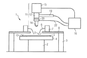
図1に示すように、プロービング装置1は移動装置としてX−Y移動ステージ2を備えている。このX−Y移動ステージ2はハウジング3内に配置されている。X−Y移動ステージ上には固定装置4が配置されている。この場合、固定装置4は角度θだけ回転可能である。固定装置4は検査対象物5を収容保持する働きをする。この検査対象物5は例えばウェーハである。このウェーハ上には多数の半導体チップが配置されている。この半導体チップ自体は個々のボンディングパッドを備えている。検査対象物5を検査するために、検査対象物は探針6によって接触させられる。その際例えば、検査対象物としてのウェーハのボンディングパッドは図示していない外側の検査配線に接触させられ、それによって電気信号が供給され、その反応が検出される。
As shown in FIG. 1, the probing apparatus 1 includes an
探針6は一端が探針ホルダ7に固定されている。この探針ホルダは一方では探針を収容保持し、他方では検査対象物と相対的に探針を高精度で位置決めする働きをする。探針ホルダ7を固定するために、固定板、いわゆる探針ホルダプレート8が設けられている。この探針ホルダプレート8上で、探針ホルダ7は負圧によって吸着して固定可能である。
One end of the
探針ホルダプレート8は開口9を有する。この開口9は一方では、観察のために検査対象物5の表面10の上方を開放する。他方では、探針6が探針ホルダプレート8の上側からこの開口9を通って検査対象物5に達することができる。
The probe holder plate 8 has an opening 9. On the one hand, this opening 9 opens above the
探針ホルダプレート8の観察開口9の上方には、画像取得装置11が配置されている。この画像取得装置11は照明装置13と対物レンズ14を有する顕微鏡12と、ビデオカメラ15とからなっている。ビデオカメラ15は画像評価ユニット16に接続されている。この画像評価ユニット16自体は適当な評価ソフトウェアを有するコンピュータからなっている。
An
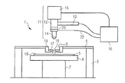
図2には、図1に関連して説明したものに類似する構造が示してある。両実施形態の違いは、別個の探針ホルダ7を有する個々の探針6の代わりに図2ではプローブカード17が使用される点にある。このプローブカード17は固有のプローブカード探針18を備え、プローブカードアダプタ19によって開口9内で保持されている。
FIG. 2 shows a structure similar to that described in connection with FIG. The difference between the two embodiments is that a
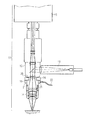
図1、2に示すような画像取得ユニットが、図3に拡大して断面図で示してある。 The image acquisition unit as shown in FIGS. 1 and 2 is shown in enlarged cross-sectional view in FIG.
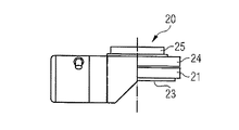
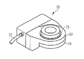
焦点合わせのために、対物レンズ14は顕微鏡対物レンズ焦点合わせシステム20を備えている。図4〜7は本発明に従って使用される顕微鏡対物レンズ焦点合わせシステム20を詳細に示している。顕微鏡対物レンズ焦点合わせシステム20は、図示していない圧電式駆動装置を収容保持する下側部分21を備えている。電圧をかけると幾何学的に変化する材料からなるこの圧電式駆動装置は、接続線22を介して、圧電式駆動装置用の図示していない制御装置を含む画像評価ユニット16に接続された電気的駆動装置である。下側部分は対物レンズ14を螺合することができる雌ねじ23を有する。上側部分24は下側部分21と相対的に軸方向に、そして顕微鏡12で使用する場合には垂直方向に移動可能であり、圧電式駆動装置によって駆動される。上側部分はねじ付き軸25を備えている。それによって、顕微鏡対物レンズ焦点合わせシステム20は、プロービング装置1において既に存在する顕微鏡12に、大きい変更なしに組み込むことができる。顕微鏡側のねじ付き軸25を対物レンズホルダ26の対物レンズねじにねじ込み可能である。雌ねじ23は対物レンズ14を収容保持する働きをする。電圧をかけると圧電式駆動装置が幾何学的に変化する結果として、対物レンズ14の焦点が調節される。
For focusing, the
この顕微鏡対物レンズ焦点合わせシステム20が接続線22を介して画像評価ユニット16に接続されているので、画像評価ユニット16にインストールされたソフトウェアによって、顕微鏡対物レンズ焦点合わせシステム20は撮影すべき画像に対応して対物レンズの焦点を極めて迅速に調節することができる。
Since the microscope objective
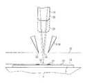
図8に示すように、検査対象物5のボンディングパッド27は、探針6がボンディングパッドに接触しておらず、従って探針6と相対的に検査対象物を動かすことができる状態にあり、ボンディングパッドは第1焦点面28内にあり、探針6の尖端29は第2焦点面30内にある。顕微鏡対物レンズ焦点合わせシステム20により、対物レンズ14は、焦点32が第1焦点面28内にある第1位置31から、対物レンズ14の焦点32が第2焦点面内にある第2位置33へもたらされる。この両位置31、33の間で対物レンズ14が往復操作され、両位置がそれぞれの画像で重ねて投影されるので、両平面は鮮明に結像される。
As shown in FIG. 8, the
1 プロービング装置
2 X−Y移動ステージ
3 ハウジング
4 固定装置
5 検査対象物
6 探針
7 探針ホルダ
8 探針ホルダプレート
9 開口
10 検査対象物の表面
11 画像取得装置
12 顕微鏡
13 照明装置
14 対物レンズ
15 ビデオカメラ
16 画像評価ユニット
17 プローブカード
18 プローブカード探針
19 プローブカードアダプタ
20 顕微鏡対物レンズ焦点合わせシステム
21 下側部分
22 接続線
23 雌ねじ
24 上側部分
25 ねじ付き軸
26 対物レンズホルダ
27 ボンディングパッド
28 第1焦点面
29 探針の尖端
30 第2焦点面
31 第1位置
32 焦点
33 第2位置
DESCRIPTION OF SYMBOLS 1
Claims (15)
このプロービング装置(1)が、移動装置(2)と、この移動装置(2)上に配置された検査対象物(5)用の固定装置(4)と、この検査対象物(5)に接触可能な探針(6;18)と、前記探針(6;18)用の保持装置(7;17)と、前記固定装置(4)の上方に配置された固定プレート(8)とを有し、前記保持装置(7;17)が、この固定プレート(8)上に固定可能であり、この固定プレート(8)が、前記検査対象物(5)の表面を見ることができるように開放している観察開口(9)を有し、
前記プロービング装置(1)が、前記観察開口(9)の上方に配置された画像取得装置(11)を有し、この画像取得装置(11)が、対物レンズ(14)と対物レンズ保持部(26)とを有する顕微鏡(12)を備え、且つ、この画像取得装置(11)が、前記検査対象物(5)の表面(10)に向けられた光ビームを発生可能な照明装置(13)を備える、当該装置において、
前記対物レンズ(14)が、前記顕微鏡(12)の垂直調節駆動装置に左右されずに、前記検査対象物(5)の前記表面(10)上の第1焦点面(30)内と探針尖端(29)の高さにある第2焦点面(30)内とに、前記対物レンズ(14)を焦点合わせ可能な顕微鏡対物レンズ焦点合わせシステム(20)を有すること、及び
前記顕微鏡対物レンズ焦点合わせシステム(20)が、前記対物レンズ保持部(26)と前記対物レンズ(14)との間に配置されている、ことを特徴とする装置。 A device for obtaining a multi-plane image by focusing with a probing device (1),
The probing device (1) is a mobile device (2), in contact with the mobile device (2) disposed on have been examined object (5) fixing device for (4), to the test object (5) Yes and; (17 7), upwardly arranged fixed plate of the fixing device (4) and (8); and; (18 6), the probe can be a probe holding device for (6 18) and, wherein the holding device (7; 17) is securable on the stationary plate (8), opened to the fixed plate (8), can be seen the surface of the test object (5) A viewing aperture (9)
The probing device (1) is, the observation image acquisition device disposed above the opening (9) has a (11), the image acquisition device (11) is an objective lens holder objective lens (14) ( 26) and equipped with a microscope (12) having, and, the image acquisition device (11) comprises inspection object (5) illumination device capable of generating a light beam directed to the surface (10) of (13) Bei obtaining, in the device,
The objective lens (14), irrespective of the vertical adjustment drive of the microscope (12), said first focal plane on the surface (10) (30) and the probe of the test object (5) and a second focal plane (30) at the height of the tip (29), said to have a focusable microscope objective lens focusing system of the objective lens (14) (20), and
The microscope objective lens focusing system (20) is arranged between the objective lens holding part (26) and the objective lens (14) .
検査対象物(5)の表面(10)から離隔された複数の探針(6;18)の複数の尖端(29)に対してこの検査対象物(5)を側面に沿って位置決めするため、顕微鏡(12)が、最初の時点に検査対象物(5)の表面(10)上に焦点合わせされ、次の第2の時点に当該両探針(6;18)の平面(30)上に焦点合わせされる、当該方法において、
顕微鏡対物レンズ焦点合わせシステム(20)が、対物レンズ保持部(26)と対物レンズ(14)との間に配置されていることによって、この対物レンズ(14)が、前記顕微鏡(12)の高さ調節に関係なく、異なる時点に両焦点面(28;30)上に焦点合わせされ、前記対物レンズ(14)の適当な焦点合わせ調節が、位置決め中に複数回変更される、ことを特徴とする方法。 A method for obtaining a multi-plane image by focusing with a probing device (1), comprising:
In order to position the inspection object (5) along the side surface with respect to the plurality of tips (29) of the plurality of probes (6; 18) separated from the surface (10) of the inspection object (5), microscope (12), is focused on the surface (10) of the inspection object to the first time point (5), following the second time point to the two probe; plane (30) on the (6 18) to be focused, in the process,
Microscope objective lens focusing system (20), by being disposed between the objective lens holding portion (26) and objective lens (14), the objective lens (14), said microscope (12) High is not involved in the regulation, in different times both focal plane; is focusing on (28 30), said adjustment appropriate focusing of the objective lens (14), characterized in being modified, it multiple times during positioning And how to.
Applications Claiming Priority (4)
| Application Number | Priority Date | Filing Date | Title |
|---|---|---|---|
| DE102006062297 | 2006-12-27 | ||
| DE102006062297.9 | 2006-12-27 | ||
| DE102007002097 | 2007-01-09 | ||
| DE102007002097.1 | 2007-01-09 |
Publications (2)
| Publication Number | Publication Date |
|---|---|
| JP2008166806A JP2008166806A (en) | 2008-07-17 |
| JP5154917B2 true JP5154917B2 (en) | 2013-02-27 |
Family
ID=39695740
Family Applications (1)
| Application Number | Title | Priority Date | Filing Date |
|---|---|---|---|
| JP2007337424A Expired - Fee Related JP5154917B2 (en) | 2006-12-27 | 2007-12-27 | Apparatus and method for acquiring a multi-plane image by focusing with a probing apparatus |
Country Status (2)
| Country | Link |
|---|---|
| US (2) | US20080212078A1 (en) |
| JP (1) | JP5154917B2 (en) |
Families Citing this family (13)
| Publication number | Priority date | Publication date | Assignee | Title |
|---|---|---|---|---|
| JP2008167447A (en) * | 2006-12-27 | 2008-07-17 | Suss Microtec Test Systems Gmbh | Apparatus and method for recording images with a prober |
| US8284246B2 (en) * | 2008-01-18 | 2012-10-09 | Olympus Corporation | Microscope system, control method used for microscope system, and recording medium for reproducing a microscope state based on microscope operation history and a microscope operation item |
| AT505671B1 (en) * | 2008-05-13 | 2009-03-15 | Evk Di Kerschhaggl Gmbh | METHOD FOR OPTICAL DETECTING OF MOVING OBJECTS |
| US8253784B2 (en) * | 2008-11-13 | 2012-08-28 | Honeywell International Inc. | Image capturing device assembly for use with test probe |
| JP4724756B2 (en) * | 2009-01-07 | 2011-07-13 | 日置電機株式会社 | Substrate inspection apparatus with illumination device for substrate inspection camera |
| DE102009059274B4 (en) * | 2009-12-22 | 2012-07-19 | Max-Joseph Kraus | Method for measuring the dynamics of changes in platelets |
| US9110131B2 (en) | 2010-04-13 | 2015-08-18 | Cascade Microtech, Inc. | Method and device for contacting a row of contact areas with probe tips |
| EP2955947B1 (en) * | 2014-06-12 | 2019-07-31 | Uros Technology S.à r.l. | Processing of preferred roaming lists |
| US10785625B2 (en) * | 2016-02-17 | 2020-09-22 | Wistron Aidge Corporation | Internet of Things (IOT) companion device |
| JP6781120B2 (en) * | 2017-08-18 | 2020-11-04 | 株式会社日本マイクロニクス | Inspection equipment |
| US10698025B2 (en) * | 2018-07-20 | 2020-06-30 | Formfactor Beaverton, Inc. | Probe systems and methods that utilize a flow-regulating structure for improved collection of an optical image of a device under test |
| DE102018121911A1 (en) * | 2018-09-07 | 2020-03-12 | Formfactor Gmbh | Method for positioning the test substrate, probes and inspection unit relative to each other and Prober for its execution |
| US12203959B2 (en) | 2022-11-18 | 2025-01-21 | Formfactor, Inc. | Methods of establishing contact between a probe tip of a probe system and a device under test, probe systems that perform the methods, and storage media that directs probe systems to perform the methods |
Family Cites Families (14)
| Publication number | Priority date | Publication date | Assignee | Title |
|---|---|---|---|---|
| JPS5917260A (en) * | 1982-07-20 | 1984-01-28 | Mitsubishi Electric Corp | Testing method for semiconductor wafer |
| JPS63204153A (en) * | 1987-02-19 | 1988-08-23 | Tokyo Electron Ltd | Probe |
| EP0606736A3 (en) * | 1992-12-11 | 1995-03-15 | Nippon Kogaku Kk | A color image scanner having multiple LEDs and color image scanning method thereof. |
| US5394100A (en) * | 1993-05-06 | 1995-02-28 | Karl Suss America, Incorporated | Probe system with automatic control of contact pressure and probe alignment |
| US5880465A (en) * | 1996-05-31 | 1999-03-09 | Kovex Corporation | Scanning confocal microscope with oscillating objective lens |
| US6002426A (en) * | 1997-07-02 | 1999-12-14 | Cerprobe Corporation | Inverted alignment station and method for calibrating needles of probe card for probe testing of integrated circuits |
| US6096567A (en) * | 1997-12-01 | 2000-08-01 | Electroglas, Inc. | Method and apparatus for direct probe sensing |
| US6590612B1 (en) * | 1999-03-18 | 2003-07-08 | Cellavision Ab | Optical system and method for composing color images from chromatically non-compensated optics |
| JP3544892B2 (en) * | 1999-05-12 | 2004-07-21 | 株式会社東京精密 | Appearance inspection method and apparatus |
| JP2004022871A (en) * | 2002-06-18 | 2004-01-22 | Nec Kansai Ltd | Manipulator type probe equipment and method for positioning probes pin thereof |
| US20040102903A1 (en) * | 2002-11-27 | 2004-05-27 | Graessle Josef A. | Biological growth plate scanner |
| DE102004034970A1 (en) * | 2004-07-16 | 2006-02-02 | Carl Zeiss Jena Gmbh | Scanning microscope and use |
| US7656172B2 (en) * | 2005-01-31 | 2010-02-02 | Cascade Microtech, Inc. | System for testing semiconductors |
| JP2008167447A (en) * | 2006-12-27 | 2008-07-17 | Suss Microtec Test Systems Gmbh | Apparatus and method for recording images with a prober |
-
2007
- 2007-12-27 US US11/964,744 patent/US20080212078A1/en not_active Abandoned
- 2007-12-27 JP JP2007337424A patent/JP5154917B2/en not_active Expired - Fee Related
-
2010
- 2010-07-30 US US12/847,723 patent/US8072586B2/en not_active Expired - Fee Related
Also Published As
| Publication number | Publication date |
|---|---|
| US20080212078A1 (en) | 2008-09-04 |
| JP2008166806A (en) | 2008-07-17 |
| US20110013011A1 (en) | 2011-01-20 |
| US8072586B2 (en) | 2011-12-06 |
Similar Documents
| Publication | Publication Date | Title |
|---|---|---|
| JP5154917B2 (en) | Apparatus and method for acquiring a multi-plane image by focusing with a probing apparatus | |
| US20080158664A1 (en) | Arrangement and method for image acquisition on a prober | |
| JP5325522B2 (en) | Combined observation system | |
| JP6009862B2 (en) | Scanning probe microscope | |
| JP5863357B2 (en) | Magnification observation apparatus, and image display method and spectroscopic method switching method of magnification observation apparatus | |
| US11681133B2 (en) | System and method for macroscopic and microscopic imaging ex-vivo tissue | |
| JP4567594B2 (en) | Microscope, sample observation method, and semiconductor inspection method | |
| CN101019058A (en) | Observation apparatus with focal position control mechanism | |
| JP2010080144A (en) | Compound microscope device and method of observing sample | |
| JPH10339845A (en) | Monitor observation type microscope | |
| CN111989608A (en) | Microscope and method for microscopically viewing a sample to present an image or three-dimensional image with extended depth of field | |
| JP6590429B1 (en) | Confocal microscope and imaging method thereof | |
| JP2007140183A (en) | Confocal scanning type microscope device | |
| JP2003315238A (en) | Measurement positioning method, cantilever and scanning probe microscope | |
| JP2019144456A (en) | Observation device | |
| JP3125124U (en) | Infrared microscope | |
| JP6255305B2 (en) | Optical microscope | |
| JP4963567B2 (en) | Minute height measuring device | |
| JP6971770B2 (en) | Magnifying observation device | |
| JP3126047B2 (en) | Scanning probe microscope | |
| CN113885187A (en) | Digital microscope and microscope kit | |
| KR102715080B1 (en) | Alignment device for microscope | |
| JP2024154082A (en) | Lens unit and magnifying observation device | |
| JP2008046362A (en) | Optical device | |
| JP2008299210A (en) | Interference objective lens and interference microscope apparatus provided with the interference objective lens |
Legal Events
| Date | Code | Title | Description |
|---|---|---|---|
| A521 | Request for written amendment filed |
Free format text: JAPANESE INTERMEDIATE CODE: A821 Effective date: 20080613 |
|
| A521 | Request for written amendment filed |
Free format text: JAPANESE INTERMEDIATE CODE: A523 Effective date: 20080613 |
|
| A621 | Written request for application examination |
Free format text: JAPANESE INTERMEDIATE CODE: A621 Effective date: 20100317 |
|
| RD04 | Notification of resignation of power of attorney |
Free format text: JAPANESE INTERMEDIATE CODE: A7424 Effective date: 20100526 |
|
| A977 | Report on retrieval |
Free format text: JAPANESE INTERMEDIATE CODE: A971007 Effective date: 20120531 |
|
| A131 | Notification of reasons for refusal |
Free format text: JAPANESE INTERMEDIATE CODE: A131 Effective date: 20120619 |
|
| A521 | Request for written amendment filed |
Free format text: JAPANESE INTERMEDIATE CODE: A523 Effective date: 20120906 |
|
| TRDD | Decision of grant or rejection written | ||
| A01 | Written decision to grant a patent or to grant a registration (utility model) |
Free format text: JAPANESE INTERMEDIATE CODE: A01 Effective date: 20121127 |
|
| A61 | First payment of annual fees (during grant procedure) |
Free format text: JAPANESE INTERMEDIATE CODE: A61 Effective date: 20121206 |
|
| FPAY | Renewal fee payment (event date is renewal date of database) |
Free format text: PAYMENT UNTIL: 20151214 Year of fee payment: 3 |
|
| R150 | Certificate of patent or registration of utility model |
Ref document number: 5154917 Country of ref document: JP Free format text: JAPANESE INTERMEDIATE CODE: R150 Free format text: JAPANESE INTERMEDIATE CODE: R150 |
|
| R250 | Receipt of annual fees |
Free format text: JAPANESE INTERMEDIATE CODE: R250 |
|
| R250 | Receipt of annual fees |
Free format text: JAPANESE INTERMEDIATE CODE: R250 |
|
| R250 | Receipt of annual fees |
Free format text: JAPANESE INTERMEDIATE CODE: R250 |
|
| R250 | Receipt of annual fees |
Free format text: JAPANESE INTERMEDIATE CODE: R250 |
|
| R250 | Receipt of annual fees |
Free format text: JAPANESE INTERMEDIATE CODE: R250 |
|
| R250 | Receipt of annual fees |
Free format text: JAPANESE INTERMEDIATE CODE: R250 |
|
| R250 | Receipt of annual fees |
Free format text: JAPANESE INTERMEDIATE CODE: R250 |
|
| R250 | Receipt of annual fees |
Free format text: JAPANESE INTERMEDIATE CODE: R250 |
|
| LAPS | Cancellation because of no payment of annual fees |