JP5043563B2 - 配線基板及びその製造方法 - Google Patents
配線基板及びその製造方法 Download PDFInfo
- Publication number
- JP5043563B2 JP5043563B2 JP2007222917A JP2007222917A JP5043563B2 JP 5043563 B2 JP5043563 B2 JP 5043563B2 JP 2007222917 A JP2007222917 A JP 2007222917A JP 2007222917 A JP2007222917 A JP 2007222917A JP 5043563 B2 JP5043563 B2 JP 5043563B2
- Authority
- JP
- Japan
- Prior art keywords
- terminal
- wiring board
- terminal pad
- mounting surface
- terminal pads
- Prior art date
- Legal status (The legal status is an assumption and is not a legal conclusion. Google has not performed a legal analysis and makes no representation as to the accuracy of the status listed.)
- Active
Links
Images


Classifications
-
- H—ELECTRICITY
- H01—ELECTRIC ELEMENTS
- H01L—SEMICONDUCTOR DEVICES NOT COVERED BY CLASS H10
- H01L2224/00—Indexing scheme for arrangements for connecting or disconnecting semiconductor or solid-state bodies and methods related thereto as covered by H01L24/00
- H01L2224/01—Means for bonding being attached to, or being formed on, the surface to be connected, e.g. chip-to-package, die-attach, "first-level" interconnects; Manufacturing methods related thereto
- H01L2224/10—Bump connectors; Manufacturing methods related thereto
- H01L2224/15—Structure, shape, material or disposition of the bump connectors after the connecting process
- H01L2224/16—Structure, shape, material or disposition of the bump connectors after the connecting process of an individual bump connector
- H01L2224/161—Disposition
- H01L2224/16151—Disposition the bump connector connecting between a semiconductor or solid-state body and an item not being a semiconductor or solid-state body, e.g. chip-to-substrate, chip-to-passive
- H01L2224/16221—Disposition the bump connector connecting between a semiconductor or solid-state body and an item not being a semiconductor or solid-state body, e.g. chip-to-substrate, chip-to-passive the body and the item being stacked
- H01L2224/16225—Disposition the bump connector connecting between a semiconductor or solid-state body and an item not being a semiconductor or solid-state body, e.g. chip-to-substrate, chip-to-passive the body and the item being stacked the item being non-metallic, e.g. insulating substrate with or without metallisation
- H01L2224/16235—Disposition the bump connector connecting between a semiconductor or solid-state body and an item not being a semiconductor or solid-state body, e.g. chip-to-substrate, chip-to-passive the body and the item being stacked the item being non-metallic, e.g. insulating substrate with or without metallisation the bump connector connecting to a via metallisation of the item
-
- H—ELECTRICITY
- H01—ELECTRIC ELEMENTS
- H01L—SEMICONDUCTOR DEVICES NOT COVERED BY CLASS H10
- H01L2224/00—Indexing scheme for arrangements for connecting or disconnecting semiconductor or solid-state bodies and methods related thereto as covered by H01L24/00
- H01L2224/01—Means for bonding being attached to, or being formed on, the surface to be connected, e.g. chip-to-package, die-attach, "first-level" interconnects; Manufacturing methods related thereto
- H01L2224/10—Bump connectors; Manufacturing methods related thereto
- H01L2224/15—Structure, shape, material or disposition of the bump connectors after the connecting process
- H01L2224/16—Structure, shape, material or disposition of the bump connectors after the connecting process of an individual bump connector
- H01L2224/161—Disposition
- H01L2224/16151—Disposition the bump connector connecting between a semiconductor or solid-state body and an item not being a semiconductor or solid-state body, e.g. chip-to-substrate, chip-to-passive
- H01L2224/16221—Disposition the bump connector connecting between a semiconductor or solid-state body and an item not being a semiconductor or solid-state body, e.g. chip-to-substrate, chip-to-passive the body and the item being stacked
- H01L2224/16225—Disposition the bump connector connecting between a semiconductor or solid-state body and an item not being a semiconductor or solid-state body, e.g. chip-to-substrate, chip-to-passive the body and the item being stacked the item being non-metallic, e.g. insulating substrate with or without metallisation
- H01L2224/16238—Disposition the bump connector connecting between a semiconductor or solid-state body and an item not being a semiconductor or solid-state body, e.g. chip-to-substrate, chip-to-passive the body and the item being stacked the item being non-metallic, e.g. insulating substrate with or without metallisation the bump connector connecting to a bonding area protruding from the surface of the item
-
- H—ELECTRICITY
- H01—ELECTRIC ELEMENTS
- H01L—SEMICONDUCTOR DEVICES NOT COVERED BY CLASS H10
- H01L2224/00—Indexing scheme for arrangements for connecting or disconnecting semiconductor or solid-state bodies and methods related thereto as covered by H01L24/00
- H01L2224/01—Means for bonding being attached to, or being formed on, the surface to be connected, e.g. chip-to-package, die-attach, "first-level" interconnects; Manufacturing methods related thereto
- H01L2224/26—Layer connectors, e.g. plate connectors, solder or adhesive layers; Manufacturing methods related thereto
- H01L2224/31—Structure, shape, material or disposition of the layer connectors after the connecting process
- H01L2224/32—Structure, shape, material or disposition of the layer connectors after the connecting process of an individual layer connector
- H01L2224/321—Disposition
- H01L2224/32151—Disposition the layer connector connecting between a semiconductor or solid-state body and an item not being a semiconductor or solid-state body, e.g. chip-to-substrate, chip-to-passive
- H01L2224/32221—Disposition the layer connector connecting between a semiconductor or solid-state body and an item not being a semiconductor or solid-state body, e.g. chip-to-substrate, chip-to-passive the body and the item being stacked
- H01L2224/32225—Disposition the layer connector connecting between a semiconductor or solid-state body and an item not being a semiconductor or solid-state body, e.g. chip-to-substrate, chip-to-passive the body and the item being stacked the item being non-metallic, e.g. insulating substrate with or without metallisation
-
- H—ELECTRICITY
- H01—ELECTRIC ELEMENTS
- H01L—SEMICONDUCTOR DEVICES NOT COVERED BY CLASS H10
- H01L2224/00—Indexing scheme for arrangements for connecting or disconnecting semiconductor or solid-state bodies and methods related thereto as covered by H01L24/00
- H01L2224/73—Means for bonding being of different types provided for in two or more of groups H01L2224/10, H01L2224/18, H01L2224/26, H01L2224/34, H01L2224/42, H01L2224/50, H01L2224/63, H01L2224/71
- H01L2224/732—Location after the connecting process
- H01L2224/73201—Location after the connecting process on the same surface
- H01L2224/73203—Bump and layer connectors
- H01L2224/73204—Bump and layer connectors the bump connector being embedded into the layer connector
-
- H—ELECTRICITY
- H01—ELECTRIC ELEMENTS
- H01L—SEMICONDUCTOR DEVICES NOT COVERED BY CLASS H10
- H01L2224/00—Indexing scheme for arrangements for connecting or disconnecting semiconductor or solid-state bodies and methods related thereto as covered by H01L24/00
- H01L2224/80—Methods for connecting semiconductor or other solid state bodies using means for bonding being attached to, or being formed on, the surface to be connected
- H01L2224/81—Methods for connecting semiconductor or other solid state bodies using means for bonding being attached to, or being formed on, the surface to be connected using a bump connector
- H01L2224/8119—Arrangement of the bump connectors prior to mounting
- H01L2224/81193—Arrangement of the bump connectors prior to mounting wherein the bump connectors are disposed on both the semiconductor or solid-state body and another item or body to be connected to the semiconductor or solid-state body
-
- H—ELECTRICITY
- H01—ELECTRIC ELEMENTS
- H01L—SEMICONDUCTOR DEVICES NOT COVERED BY CLASS H10
- H01L2224/00—Indexing scheme for arrangements for connecting or disconnecting semiconductor or solid-state bodies and methods related thereto as covered by H01L24/00
- H01L2224/80—Methods for connecting semiconductor or other solid state bodies using means for bonding being attached to, or being formed on, the surface to be connected
- H01L2224/81—Methods for connecting semiconductor or other solid state bodies using means for bonding being attached to, or being formed on, the surface to be connected using a bump connector
- H01L2224/818—Bonding techniques
- H01L2224/81801—Soldering or alloying
- H01L2224/81815—Reflow soldering
-
- H—ELECTRICITY
- H01—ELECTRIC ELEMENTS
- H01L—SEMICONDUCTOR DEVICES NOT COVERED BY CLASS H10
- H01L2224/00—Indexing scheme for arrangements for connecting or disconnecting semiconductor or solid-state bodies and methods related thereto as covered by H01L24/00
- H01L2224/91—Methods for connecting semiconductor or solid state bodies including different methods provided for in two or more of groups H01L2224/80 - H01L2224/90
- H01L2224/92—Specific sequence of method steps
- H01L2224/921—Connecting a surface with connectors of different types
- H01L2224/9212—Sequential connecting processes
- H01L2224/92122—Sequential connecting processes the first connecting process involving a bump connector
- H01L2224/92125—Sequential connecting processes the first connecting process involving a bump connector the second connecting process involving a layer connector
-
- H—ELECTRICITY
- H01—ELECTRIC ELEMENTS
- H01L—SEMICONDUCTOR DEVICES NOT COVERED BY CLASS H10
- H01L2924/00—Indexing scheme for arrangements or methods for connecting or disconnecting semiconductor or solid-state bodies as covered by H01L24/00
- H01L2924/15—Details of package parts other than the semiconductor or other solid state devices to be connected
- H01L2924/151—Die mounting substrate
- H01L2924/1517—Multilayer substrate
- H01L2924/15172—Fan-out arrangement of the internal vias
- H01L2924/15174—Fan-out arrangement of the internal vias in different layers of the multilayer substrate
-
- H—ELECTRICITY
- H01—ELECTRIC ELEMENTS
- H01L—SEMICONDUCTOR DEVICES NOT COVERED BY CLASS H10
- H01L2924/00—Indexing scheme for arrangements or methods for connecting or disconnecting semiconductor or solid-state bodies as covered by H01L24/00
- H01L2924/15—Details of package parts other than the semiconductor or other solid state devices to be connected
- H01L2924/151—Die mounting substrate
- H01L2924/153—Connection portion
- H01L2924/1531—Connection portion the connection portion being formed only on the surface of the substrate opposite to the die mounting surface
- H01L2924/15312—Connection portion the connection portion being formed only on the surface of the substrate opposite to the die mounting surface being a pin array, e.g. PGA
Description
前記半導体搭載面の複数の端子パッドは、めっきにより形成されており、平面形状が正多角形に形成されるとともに、立体形状は中央部が突出した凸形状であり、
前記正多角形の内心が、所定のピッチで配列されており、
前記配線基板は、樹脂からなる絶縁層と、配線層が積層した構成を有しており、
前記配線基板の前記半導体搭載面とは反対側の面は、外部接続端子面であって、
該外部接続端子面には半田接合用の複数の端子パッドが形成されており、
前記外部接続端子面の複数の端子パッドは、めっきにより形成されており、平面形状が正多角形に形成されるとともに、立体形状は中央部が突出した凸形状であり、
前記正多角形の内心が、所定のピッチで配列されていることを特徴とする。
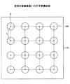
前記半導体搭載面の複数の端子パッドおよび/または前記外部接続端子面の複数の端子パッドは、格子をなして配列され、
前記正多角形は、前記格子と平行な辺で形成された正方形であることを特徴とする。
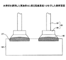
前記半導体搭載面の複数の端子パッドおよび/または前記外部接続端子面の複数の端子パッドの立体形状が、端部は平面状であり、中央部のみ段をなして突出した凸形状であることを特徴とする。
第5の発明は、第1〜3のいずれか一つの発明に係る配線基板において、
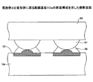
前記半導体搭載面の複数の端子パッドおよび/または前記外部接続端子面に形成された複数の端子パッドの立体形状が、略球面状に、端部から中央部に滑らかに突出した凸形状を有することを特徴とする。
前記半導体搭載面となる絶縁層の表面に前記端子パッドが形成されており、
前記半導体搭載面となる前記絶縁層の裏面には、前記端子パッドの裏面を露出するビア穴が形成され、
前記絶縁層裏面には、前記ビア穴を介して前記端子パッドの裏面に接続される前記配線層が形成されていることを特徴とする。
金属からなる支持体の表面に、正多角形の開口を有するレジストを形成するレジストパターンニング工程と、
エッチングを行い、前記レジストに覆われていない部分の前記支持体に凹状の窪みを形成するエッチング工程と、
前記窪みに、電解めっきにより半導体搭載面の端子パッドを形成する半導体搭載面端子パッド形成工程と、
前記レジストを除去するレジスト除去工程と、
前記半導体搭載面の端子パッドが形成された前記支持体の表面に、絶縁層を形成する絶縁層形成工程と、
前記絶縁層上に、前記半導体搭載面の端子パッドと接続された配線層を形成する配線層形成工程と、
最も上層の配線層上に、外部接続端子面の端子パッドを露出する正多角形の開口を有するソルダレジストを形成するソルダレジスト形成工程と、
前記支持体を、エッチングにより除去する支持体除去工程と、を含み、
前記ソルダレジストが有する正多角形の開口から露出した外部接続端子面の端子パッドは、中央部が突出した凸形状の立体形状を有しており、
前記ソルダレジストが有する正多角形の開口は、その内心が所定のピッチで配列されていることを特徴とする。
第8の発明は、第7の発明に係る配線基板の製造方法において、前記半導体搭載面の端子パッドおよび/または前記外部接続端子面の端子パッドの立体形状が、端部は平面状であり、中央部のみ段をなして突出した凸形状であることを特徴とする。
第9の発明は、第7の発明に係る配線基板の製造方法において、前記半導体搭載面の端子パッドおよび/または前記外部接続端子面の端子パッドの立体形状が、略球面状に、端部から中央部に滑らかに突出した凸形状を有することを特徴とする。
第10の発明は、第7〜第9の発明に係る配線基板の製造方法において、前記絶縁層に前記半導体搭載面の端子パッドの上面を露出するビア穴を形成する工程をさらに有しており、
前記配線層形成工程においては、前記ビア穴を介して前記半導体搭載面の端子パッド上面に接続された配線層を形成することを特徴とする。
第11の発明は、第7〜9の発明に係る配線基板の製造方法において、前記絶縁層は樹脂からなり、前記配線層がめっきからなることを特徴とする。
通常は、図10(e)の状態を上下反対とし、端子パッド22が形成された半導体素子面を上側にして半導体素子を搭載し、端子パッド24が形成された外部接続端子面を下側にして外部接続用に用いる場合が多い。
20、20a〜20g、21、21a〜21c、22、23、24、27、28 端子パッド
25 金めっき層
26 ニッケルめっき層
30 支持体
31 窪み
40 めっきレジスト
41、71 開口
50、51、52 絶縁層
55 ビア穴
60、61、62 配線層
70 ソルダレジスト
80 半導体素子
85 ピン
86 ヘッド部
87 軸部
90 半田(プレソルダ)
91 バンプ
100 アンダーフィル樹脂
120、120a〜120g、121、121a〜121c 内接円
Claims (11)
- 半導体素子が搭載される半導体搭載面に半田接合用の複数の端子パッドを有する配線基板であって、
前記半導体搭載面の複数の端子パッドは、めっきにより形成されており、平面形状が正多角形に形成されるとともに、立体形状は中央部が突出した凸形状であり、
前記正多角形の内心が、所定のピッチで配列されており、
前記配線基板は、樹脂からなる絶縁層と、配線層が積層した構成を有しており、
前記配線基板の前記半導体搭載面とは反対側の面は、外部接続端子面であって、
該外部接続端子面には半田接合用の複数の端子パッドが形成されており、
前記外部接続端子面の複数の端子パッドは、めっきにより形成されており、平面形状が正多角形に形成されるとともに、立体形状は中央部が突出した凸形状であり、
前記正多角形の内心が、所定のピッチで配列されていることを特徴とする配線基板。 - 前記半導体搭載面の複数の端子パッドおよび/または前記外部接続端子面の複数の端子パッドは、前記正多角形が同じ向きとなるように形成されたことを特徴とする請求項1に記載の配線基板。
- 前記半導体搭載面の複数の端子パッドおよび/または前記外部接続端子面の複数の端子パッドは、格子をなして配列され、
前記正多角形は、前記格子と平行な辺で形成された正方形であることを特徴とする請求項1又は2に記載の配線基板。 - 前記半導体搭載面の複数の端子パッドおよび/または前記外部接続端子面の複数の端子パッドの立体形状が、端部は平面状であり、中央部のみ段をなして突出した凸形状であることを特徴とする請求項1乃至3いずれか一項に記載の配線基板。
- 前記半導体搭載面の複数の端子パッドおよび/または前記外部接続端子面の複数の端子パッドの立体形状が、略球面状に、端部から中央部に滑らかに突出した凸形状を有することを特徴とする請求項1乃至3いずれか一項に記載の配線基板。
- 前記半導体搭載面となる絶縁層の表面に前記端子パッドが形成されており、
前記半導体搭載面となる前記絶縁層の裏面には、前記端子パッドの裏面を露出するビア穴が形成され、
前記絶縁層裏面には、前記ビア穴を介して前記端子パッドの裏面に接続される前記配線層が形成されていることを特徴とする請求項1乃至5いずれか一項に記載の配線基板。 - 平面形状が正多角形であり、立体形状が中央部の突出した凸形状である端子パッドを有する配線基板の製造方法であって、
金属からなる支持体の表面に、正多角形の開口を有するレジストを形成するレジストパターンニング工程と、
エッチングを行い、前記レジストに覆われていない部分の前記支持体に凹状の窪みを形成するエッチング工程と、
前記窪みに、電解めっきにより半導体搭載面の端子パッドを形成する半導体搭載面端子パッド形成工程と、
前記レジストを除去するレジスト除去工程と、
前記半導体搭載面の端子パッドが形成された前記支持体の表面に、絶縁層を形成する絶縁層形成工程と、
前記絶縁層上に、前記半導体搭載面の端子パッドと接続された配線層を形成する配線層形成工程と、
最も上層の配線層上に、外部接続端子面の端子パッドを露出する正多角形の開口を有するソルダレジストを形成するソルダレジスト形成工程と、
前記支持体を、エッチングにより除去する支持体除去工程と、を含み、
前記ソルダレジストが有する正多角形の開口から露出した外部接続端子面の端子パッドは、中央部が突出した凸形状の立体形状を有しており、
前記ソルダレジストが有する正多角形の開口は、その内心が所定のピッチで配列されていることを特徴とする配線基板の製造方法。 - 前記半導体搭載面の端子パッドおよび/または前記外部接続端子面の端子パッドの立体形状が、端部は平面状であり、中央部のみ段をなして突出した凸形状であることを特徴とする請求項7に記載の配線基板の製造方法。
- 前記半導体搭載面の端子パッドおよび/または前記外部接続端子面の端子パッドの立体形状が、略球面状に、端部から中央部に滑らかに突出した凸形状を有することを特徴とする請求項7に記載の配線基板の製造方法。
- 前記絶縁層に前記半導体搭載面の端子パッドの上面を露出するビア穴を形成する工程をさらに有しており、
前記配線層形成工程においては、前記ビア穴を介して前記半導体搭載面の端子パッド上面に接続された配線層を形成することを特徴とする請求項7乃至9いずれか一項に記載の配線基板の製造方法。 - 前記絶縁層は樹脂からなり、前記配線層がめっきからなることを特徴とする請求項7乃至10いずれか一項に記載の配線基板の製造方法。
Priority Applications (1)
| Application Number | Priority Date | Filing Date | Title |
|---|---|---|---|
| JP2007222917A JP5043563B2 (ja) | 2007-08-29 | 2007-08-29 | 配線基板及びその製造方法 |
Applications Claiming Priority (1)
| Application Number | Priority Date | Filing Date | Title |
|---|---|---|---|
| JP2007222917A JP5043563B2 (ja) | 2007-08-29 | 2007-08-29 | 配線基板及びその製造方法 |
Related Child Applications (1)
| Application Number | Title | Priority Date | Filing Date |
|---|---|---|---|
| JP2012155863A Division JP5399539B2 (ja) | 2012-07-11 | 2012-07-11 | 配線基板及びその製造方法 |
Publications (3)
| Publication Number | Publication Date |
|---|---|
| JP2009054969A JP2009054969A (ja) | 2009-03-12 |
| JP2009054969A5 JP2009054969A5 (ja) | 2010-07-29 |
| JP5043563B2 true JP5043563B2 (ja) | 2012-10-10 |
Family
ID=40505745
Family Applications (1)
| Application Number | Title | Priority Date | Filing Date |
|---|---|---|---|
| JP2007222917A Active JP5043563B2 (ja) | 2007-08-29 | 2007-08-29 | 配線基板及びその製造方法 |
Country Status (1)
| Country | Link |
|---|---|
| JP (1) | JP5043563B2 (ja) |
Families Citing this family (7)
| Publication number | Priority date | Publication date | Assignee | Title |
|---|---|---|---|---|
| JP5342422B2 (ja) * | 2009-12-10 | 2013-11-13 | ルネサスエレクトロニクス株式会社 | 半導体装置およびその製造方法 |
| CN102378484B (zh) * | 2010-08-13 | 2017-02-08 | 雅达电子有限公司 | 提高焊点可靠性方法、印刷电路板、封装器件及封装模块 |
| CN105357900A (zh) * | 2015-12-03 | 2016-02-24 | 北京浩瀚深度信息技术股份有限公司 | 消除异形smd元器件回流焊接位移的pad设计方法 |
| KR102519736B1 (ko) * | 2018-01-17 | 2023-04-11 | 주식회사 루멘스 | Led 디스플레이 모듈 |
| US20210035898A1 (en) * | 2019-07-30 | 2021-02-04 | Powertech Technology Inc. | Package structure and manufacturing method thereof |
| CN111863759A (zh) | 2020-03-26 | 2020-10-30 | 北京小米移动软件有限公司 | 芯片、电路板、电路板组件及电子设备 |
| CN113921491A (zh) * | 2020-07-08 | 2022-01-11 | 北京小米移动软件有限公司 | 芯片、电路板及电子设备 |
Family Cites Families (6)
| Publication number | Priority date | Publication date | Assignee | Title |
|---|---|---|---|---|
| JPH0846079A (ja) * | 1994-07-28 | 1996-02-16 | Matsushita Electric Ind Co Ltd | 半導体装置 |
| JPH11204570A (ja) * | 1998-01-08 | 1999-07-30 | Sumitomo Metal Smi Electron Devices Inc | 外部入出力端子 |
| JP4366777B2 (ja) * | 1999-09-01 | 2009-11-18 | パナソニック株式会社 | 電子部品 |
| JP2004200187A (ja) * | 2002-12-16 | 2004-07-15 | Nikon Corp | プリント配線板 |
| JP4541763B2 (ja) * | 2004-01-19 | 2010-09-08 | 新光電気工業株式会社 | 回路基板の製造方法 |
| JP2005244149A (ja) * | 2004-01-26 | 2005-09-08 | Kyocera Corp | 配線基板 |
-
2007
- 2007-08-29 JP JP2007222917A patent/JP5043563B2/ja active Active
Also Published As
| Publication number | Publication date |
|---|---|
| JP2009054969A (ja) | 2009-03-12 |
Similar Documents
| Publication | Publication Date | Title |
|---|---|---|
| JP5043563B2 (ja) | 配線基板及びその製造方法 | |
| US9111818B2 (en) | Packaging substrate | |
| TWI395274B (zh) | 製造電路基材的方法及製造電子部件封裝結構的方法 | |
| US7838982B2 (en) | Semiconductor package having connecting bumps | |
| JP4146864B2 (ja) | 配線基板及びその製造方法、並びに半導体装置及び半導体装置の製造方法 | |
| KR100800478B1 (ko) | 적층형 반도체 패키지 및 그의 제조방법 | |
| US8445329B2 (en) | Circuit board with oval micro via | |
| US8373276B2 (en) | Printed wiring board and method for manufacturing the same | |
| JP4980295B2 (ja) | 配線基板の製造方法、及び半導体装置の製造方法 | |
| JP6247032B2 (ja) | 配線基板、半導体装置及び配線基板の製造方法 | |
| US7484293B2 (en) | Semiconductor package and manufacturing method therefor | |
| US20080265411A1 (en) | Structure of packaging substrate and method for making the same | |
| TWI713427B (zh) | 封裝體的接著結構及其製造方法 | |
| CN110729254B (zh) | 封装体的接着结构及其制造方法 | |
| JP2011014944A (ja) | 電子部品実装構造体の製造方法 | |
| JP2019140174A (ja) | プリント配線板およびプリント配線板の製造方法 | |
| JP4494249B2 (ja) | 半導体装置 | |
| TWI646639B (zh) | 半導體封裝 | |
| JP5399539B2 (ja) | 配線基板及びその製造方法 | |
| JP3802824B2 (ja) | 配線基板の製造方法 | |
| JP2009224461A (ja) | 配線基板及びその製造方法 | |
| JP2006253167A (ja) | キャビティ構造プリント配線板の製造方法及び実装構造 | |
| US11749596B2 (en) | Wiring substrate | |
| JP3898628B2 (ja) | 配線基板及び、その製造方法 | |
| TWI575619B (zh) | 半導體封裝結構及其製作方法 |
Legal Events
| Date | Code | Title | Description |
|---|---|---|---|
| A521 | Written amendment |
Free format text: JAPANESE INTERMEDIATE CODE: A523 Effective date: 20100611 |
|
| A621 | Written request for application examination |
Free format text: JAPANESE INTERMEDIATE CODE: A621 Effective date: 20100611 |
|
| A977 | Report on retrieval |
Free format text: JAPANESE INTERMEDIATE CODE: A971007 Effective date: 20111206 |
|
| A131 | Notification of reasons for refusal |
Free format text: JAPANESE INTERMEDIATE CODE: A131 Effective date: 20111213 |
|
| A521 | Written amendment |
Free format text: JAPANESE INTERMEDIATE CODE: A523 Effective date: 20120210 |
|
| A131 | Notification of reasons for refusal |
Free format text: JAPANESE INTERMEDIATE CODE: A131 Effective date: 20120403 |
|
| A521 | Written amendment |
Free format text: JAPANESE INTERMEDIATE CODE: A523 Effective date: 20120531 |
|
| TRDD | Decision of grant or rejection written | ||
| A01 | Written decision to grant a patent or to grant a registration (utility model) |
Free format text: JAPANESE INTERMEDIATE CODE: A01 Effective date: 20120619 |
|
| A01 | Written decision to grant a patent or to grant a registration (utility model) |
Free format text: JAPANESE INTERMEDIATE CODE: A01 |
|
| A61 | First payment of annual fees (during grant procedure) |
Free format text: JAPANESE INTERMEDIATE CODE: A61 Effective date: 20120712 |
|
| R150 | Certificate of patent or registration of utility model |
Ref document number: 5043563 Country of ref document: JP Free format text: JAPANESE INTERMEDIATE CODE: R150 Free format text: JAPANESE INTERMEDIATE CODE: R150 |
|
| FPAY | Renewal fee payment (event date is renewal date of database) |
Free format text: PAYMENT UNTIL: 20150720 Year of fee payment: 3 |