JP4875993B2 - 電源回路接続装置 - Google Patents
電源回路接続装置 Download PDFInfo
- Publication number
- JP4875993B2 JP4875993B2 JP2007007737A JP2007007737A JP4875993B2 JP 4875993 B2 JP4875993 B2 JP 4875993B2 JP 2007007737 A JP2007007737 A JP 2007007737A JP 2007007737 A JP2007007737 A JP 2007007737A JP 4875993 B2 JP4875993 B2 JP 4875993B2
- Authority
- JP
- Japan
- Prior art keywords
- lever
- housing
- power supply
- supply circuit
- terminals
- Prior art date
- Legal status (The legal status is an assumption and is not a legal conclusion. Google has not performed a legal analysis and makes no representation as to the accuracy of the status listed.)
- Active
Links
Images


Classifications
-
- H—ELECTRICITY
- H01—ELECTRIC ELEMENTS
- H01R—ELECTRICALLY-CONDUCTIVE CONNECTIONS; STRUCTURAL ASSOCIATIONS OF A PLURALITY OF MUTUALLY-INSULATED ELECTRICAL CONNECTING ELEMENTS; COUPLING DEVICES; CURRENT COLLECTORS
- H01R13/00—Details of coupling devices of the kinds covered by groups H01R12/70 or H01R24/00 - H01R33/00
- H01R13/62—Means for facilitating engagement or disengagement of coupling parts or for holding them in engagement
- H01R13/629—Additional means for facilitating engagement or disengagement of coupling parts, e.g. aligning or guiding means, levers, gas pressure electrical locking indicators, manufacturing tolerances
- H01R13/62933—Comprising exclusively pivoting lever
- H01R13/62938—Pivoting lever comprising own camming means
-
- H—ELECTRICITY
- H01—ELECTRIC ELEMENTS
- H01H—ELECTRIC SWITCHES; RELAYS; SELECTORS; EMERGENCY PROTECTIVE DEVICES
- H01H85/00—Protective devices in which the current flows through a part of fusible material and this current is interrupted by displacement of the fusible material when this current becomes excessive
- H01H85/54—Protective devices wherein the fuse is carried, held, or retained by an intermediate or auxiliary part removable from the base, or used as sectionalisers
- H01H85/547—Protective devices wherein the fuse is carried, held, or retained by an intermediate or auxiliary part removable from the base, or used as sectionalisers with sliding fuse carrier
-
- H—ELECTRICITY
- H01—ELECTRIC ELEMENTS
- H01H—ELECTRIC SWITCHES; RELAYS; SELECTORS; EMERGENCY PROTECTIVE DEVICES
- H01H9/00—Details of switching devices, not covered by groups H01H1/00 - H01H7/00
- H01H9/08—Arrangements to facilitate replacement of a switch, e.g. cartridge housing
- H01H9/085—Arrangements to facilitate replacement of a switch, e.g. cartridge housing contact separation effected by removing contact carrying element
-
- H—ELECTRICITY
- H01—ELECTRIC ELEMENTS
- H01R—ELECTRICALLY-CONDUCTIVE CONNECTIONS; STRUCTURAL ASSOCIATIONS OF A PLURALITY OF MUTUALLY-INSULATED ELECTRICAL CONNECTING ELEMENTS; COUPLING DEVICES; CURRENT COLLECTORS
- H01R13/00—Details of coupling devices of the kinds covered by groups H01R12/70 or H01R24/00 - H01R33/00
- H01R13/62—Means for facilitating engagement or disengagement of coupling parts or for holding them in engagement
- H01R13/629—Additional means for facilitating engagement or disengagement of coupling parts, e.g. aligning or guiding means, levers, gas pressure electrical locking indicators, manufacturing tolerances
- H01R13/62933—Comprising exclusively pivoting lever
- H01R13/6295—Pivoting lever comprising means indicating incorrect coupling of mating connectors
-
- H—ELECTRICITY
- H01—ELECTRIC ELEMENTS
- H01R—ELECTRICALLY-CONDUCTIVE CONNECTIONS; STRUCTURAL ASSOCIATIONS OF A PLURALITY OF MUTUALLY-INSULATED ELECTRICAL CONNECTING ELEMENTS; COUPLING DEVICES; CURRENT COLLECTORS
- H01R13/00—Details of coupling devices of the kinds covered by groups H01R12/70 or H01R24/00 - H01R33/00
- H01R13/62—Means for facilitating engagement or disengagement of coupling parts or for holding them in engagement
- H01R13/629—Additional means for facilitating engagement or disengagement of coupling parts, e.g. aligning or guiding means, levers, gas pressure electrical locking indicators, manufacturing tolerances
- H01R13/62933—Comprising exclusively pivoting lever
- H01R13/62955—Pivoting lever comprising supplementary/additional locking means
-
- H—ELECTRICITY
- H01—ELECTRIC ELEMENTS
- H01R—ELECTRICALLY-CONDUCTIVE CONNECTIONS; STRUCTURAL ASSOCIATIONS OF A PLURALITY OF MUTUALLY-INSULATED ELECTRICAL CONNECTING ELEMENTS; COUPLING DEVICES; CURRENT COLLECTORS
- H01R13/00—Details of coupling devices of the kinds covered by groups H01R12/70 or H01R24/00 - H01R33/00
- H01R13/66—Structural association with built-in electrical component
- H01R13/70—Structural association with built-in electrical component with built-in switch
- H01R13/701—Structural association with built-in electrical component with built-in switch the switch being actuated by an accessory, e.g. cover, locking member
-
- H—ELECTRICITY
- H01—ELECTRIC ELEMENTS
- H01R—ELECTRICALLY-CONDUCTIVE CONNECTIONS; STRUCTURAL ASSOCIATIONS OF A PLURALITY OF MUTUALLY-INSULATED ELECTRICAL CONNECTING ELEMENTS; COUPLING DEVICES; CURRENT COLLECTORS
- H01R13/00—Details of coupling devices of the kinds covered by groups H01R12/70 or H01R24/00 - H01R33/00
- H01R13/66—Structural association with built-in electrical component
- H01R13/70—Structural association with built-in electrical component with built-in switch
- H01R13/71—Contact members of coupling parts operating as switch, e.g. linear or rotational movement required after mechanical engagement of coupling part to establish electrical connection
-
- H—ELECTRICITY
- H01—ELECTRIC ELEMENTS
- H01R—ELECTRICALLY-CONDUCTIVE CONNECTIONS; STRUCTURAL ASSOCIATIONS OF A PLURALITY OF MUTUALLY-INSULATED ELECTRICAL CONNECTING ELEMENTS; COUPLING DEVICES; CURRENT COLLECTORS
- H01R2201/00—Connectors or connections adapted for particular applications
- H01R2201/26—Connectors or connections adapted for particular applications for vehicles
-
- H—ELECTRICITY
- H01—ELECTRIC ELEMENTS
- H01R—ELECTRICALLY-CONDUCTIVE CONNECTIONS; STRUCTURAL ASSOCIATIONS OF A PLURALITY OF MUTUALLY-INSULATED ELECTRICAL CONNECTING ELEMENTS; COUPLING DEVICES; CURRENT COLLECTORS
- H01R33/00—Coupling devices specially adapted for supporting apparatus and having one part acting as a holder providing support and electrical connection via a counterpart which is structurally associated with the apparatus, e.g. lamp holders; Separate parts thereof
- H01R33/945—Holders with built-in electrical component
- H01R33/96—Holders with built-in electrical component with switch operated by engagement or disengagement of coupling
-
- H—ELECTRICITY
- H01—ELECTRIC ELEMENTS
- H01R—ELECTRICALLY-CONDUCTIVE CONNECTIONS; STRUCTURAL ASSOCIATIONS OF A PLURALITY OF MUTUALLY-INSULATED ELECTRICAL CONNECTING ELEMENTS; COUPLING DEVICES; CURRENT COLLECTORS
- H01R33/00—Coupling devices specially adapted for supporting apparatus and having one part acting as a holder providing support and electrical connection via a counterpart which is structurally associated with the apparatus, e.g. lamp holders; Separate parts thereof
- H01R33/97—Holders with separate means to prevent loosening of the coupling or unauthorised removal of apparatus held
-
- H—ELECTRICITY
- H01—ELECTRIC ELEMENTS
- H01R—ELECTRICALLY-CONDUCTIVE CONNECTIONS; STRUCTURAL ASSOCIATIONS OF A PLURALITY OF MUTUALLY-INSULATED ELECTRICAL CONNECTING ELEMENTS; COUPLING DEVICES; CURRENT COLLECTORS
- H01R33/00—Coupling devices specially adapted for supporting apparatus and having one part acting as a holder providing support and electrical connection via a counterpart which is structurally associated with the apparatus, e.g. lamp holders; Separate parts thereof
- H01R33/975—Holders with resilient means for protecting apparatus against vibrations or shocks
Landscapes
- Details Of Connecting Devices For Male And Female Coupling (AREA)
- Mechanical Control Devices (AREA)
- Position Input By Displaying (AREA)
- Connector Housings Or Holding Contact Members (AREA)
Description
また、本発明による電源回路接続方法は、まず、一対のメイン回路用端子と一対の嵌合検知用端子とが設けられた第1ハウジングに、第2ハウジングに回動可能に設けられたレバーを係合する。レバーの位置を第1の所定の位置にした状態で、第1ハウジングに第2ハウジングを嵌合するとともに、第2ハウジング内に設けた第1のスイッチ端子を介して一対のメイン回路用端子同士を接続する。さらにレバーを第1の所定位置を超えて第2の所定位置まで回動操作し、レバーに設けられた第2のスイッチ端子を介して一対の嵌合検知用端子同士を接続し、電源回路を導通状態とする。
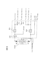
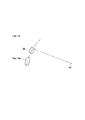
図1は、電気自動車もしくはハイブリッド車の電源回路の一部を示す電気回路図である。図1に示すように本実施の形態に係る電源回路接続装置100(以下、サービスディスコネクトスイッチ、略してSDSWと呼ぶ)は、電源回路の途中に設けられ、バッテリ同士を遮断および接続するメイン回路スイッチとして機能する。すなわちSDSW100は、後述するように着脱可能な一対のコネクタハウジングを有し、コネクタハウジングの着脱によりバッテリの中間電位部abを遮断および接続する。バッテリからの電気はリレーR1,R2を介して図示しないインバータと、14V用および42V用のDC/DCコンバータに流れる。バッテリからの電気は電流センサCSと電圧センサ(不図示)で検出される。
(1)レバー3の回動操作により第2ハウジング2を第1ハウジング1内に嵌合するとともに、レバー3のコネクタ部34を第1ハウジング1のコネクタ部12に嵌合し、メイン回路スイッチと嵌合検知スイッチをオンするようにした。これによりレバー3をスライド操作することなくSDSW100を作動することができる。このため、レバー3のスライドのためのスペースが不要であり、SDSW100を小型化できる。
(2)レバー3を一方向に回動操作することによりメイン回路スイッチと嵌合検知スイッチをオンまたはオフするので、SDSW100の操作が容易であり、緊急時等に素早くSDSW100を操作できる。
(4)ロック部材26の上端262cを後方に押してロック部材26をレバー3の回動軌跡L外に退避させるので、メイン回路嵌合状態から完全嵌合状態への移行も容易である。
(5)ロック部材26によりレバー3を完全嵌合位置にロックするので、走行時の車両振動等によってSDSW100のコネクタハウジングが離脱することはなく、電源回路を安定して導通状態とすることができる。
(7)コネクタハウジングをスライドさせる必要がないので、ハウジング内に余剰の収容スペースが形成されず、SDSW1へのごみ等の混入を防ぐことができる。
(8)端子36の左右内側の隙間を下部にいくほど狭くしたので、端子36の入口の隙間が狭くなり、内部にごみが入りにくい。
(9)コネクタ部34の開口端面34aに連なり、コネクタ部34の後面に開口部34bを設けたので、端子36の内部にごみが入ったとしてもそれを容易に取り除くことができる。完全嵌合状態では開口部34bは隠れるので、開口部34bからごみが入ることもない。
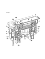
2 第2ハウジング
3 レバー
12 コネクタ部
13 ガイドピン
14a,14b 端子(メイン回路用端子)
16a,16b 端子(嵌合検知用端子)
26 ロック部材
27a,27b 端子(第1のスイッチ端子)
34 コネクタ部
34a 開口端面
34b 開口部
35 ガイド溝
36 端子(第2のスイッチ端子)
Claims (6)
- スイッチ端子を介して一対のメイン回路用端子同士を接続するとともに、一対の嵌合検知用端子同士を接続することにより、電源回路を導通状態とする電源回路接続装置であって、
前記一対のメイン回路用端子と前記一対の嵌合検知用端子とが設けられた第1ハウジングと、
前記第1ハウジングに嵌合および離脱する第2ハウジングと、
前記第2ハウジングに回動可能に支持されたレバーと、
前記レバーの回動により前記第2ハウジングを前記第1ハウジングに嵌合および離脱する嵌合離脱機構とを備え、
前記第2ハウジングには、前記レバーの位置を第1の所定の位置にした状態で、前記一対のメイン回路用端子同士を接続する第1のスイッチ端子が設けられ、
前記レバーには、前記第1の所定位置を超える第2の所定位置への前記レバーの回動操作によって、前記一対のメイン回路用端子同士の接続を維持したまま、前記一対の嵌合検知用端子同士を接続する第2のスイッチ端子が設けられ、
前記嵌合離脱機構は、
前記レバーの回動操作によりガイドピンに沿って移動するガイド溝を有し、
前記ガイド溝は、
前記第2ハウジングが前記第1ハウジングに嵌合した状態から前記一対の嵌合検知用端子同士が接続された状態になるまでは、前記レバーの回転軸から前記ガイド溝までの距離が一定となるよう形成されていることを特徴とする
電源回路接続装置。 - 請求項1に記載の電源回路接続装置において、
前記レバーを前記第2の所定位置でロックするロック機構を設けることを特徴とする電源回路接続装置。 - 請求項2に記載の電源回路接続装置において、
前記ロック機構は、前記レバーの回動軌跡上から回動軌跡外に移動して前記第1の所定位置から前記第2の所定位置への前記レバーの回動操作を許可し、前記回動軌跡外から回動軌跡上に移動して前記第1の所定位置から前記第2の所定位置への前記レバーの回動操作を阻止する可動部材を有することを特徴とする電源回路接続装置。 - 請求項1〜3のいずれか1項に記載の電源回路接続装置において、
前記レバーの先端部には、少なくともレバー回動方向の一端面が開口したケース部が設けられ、この開口端面から突出することなく前記ケース部内に前記第2のスイッチ端子が設けられるとともに、
前記第1ハウジングには、前記ケース部を収容する収容部が設けられ、この収容部内に前記嵌合検知用端子が収容部の開口端面から突出することなく設けられることを特徴とする電源回路接続装置。 - 請求項4に記載の電源回路接続装置において、
レバー回動軸側における前記ケース部の側端面には、前記開口端面の開口に連なり開口部が設けられことを特徴とする電源回路接続装置。 - 請求項1〜5のいずれか1項に記載の電源回路接続装置において、
前記嵌合検知用端子は、少なくとも先端部が前記第2のスイッチ端子の回動軌跡に沿って設けられることを特徴とする電源回路接続装置。
Priority Applications (4)
| Application Number | Priority Date | Filing Date | Title |
|---|---|---|---|
| JP2007007737A JP4875993B2 (ja) | 2007-01-17 | 2007-01-17 | 電源回路接続装置 |
| CN2008100019337A CN101226833B (zh) | 2007-01-17 | 2008-01-03 | 电源电路连接器及电源电路的连接方法 |
| EP08000377.5A EP1947744B1 (en) | 2007-01-17 | 2008-01-10 | Power supply circuit connector and method of connecting power supply circuit |
| US12/013,852 US7872206B2 (en) | 2007-01-17 | 2008-01-14 | Power supply circuit connector and method of connecting power supply circuit |
Applications Claiming Priority (1)
| Application Number | Priority Date | Filing Date | Title |
|---|---|---|---|
| JP2007007737A JP4875993B2 (ja) | 2007-01-17 | 2007-01-17 | 電源回路接続装置 |
Publications (2)
| Publication Number | Publication Date |
|---|---|
| JP2008176969A JP2008176969A (ja) | 2008-07-31 |
| JP4875993B2 true JP4875993B2 (ja) | 2012-02-15 |
Family
ID=39323582
Family Applications (1)
| Application Number | Title | Priority Date | Filing Date |
|---|---|---|---|
| JP2007007737A Active JP4875993B2 (ja) | 2007-01-17 | 2007-01-17 | 電源回路接続装置 |
Country Status (4)
| Country | Link |
|---|---|
| US (1) | US7872206B2 (ja) |
| EP (1) | EP1947744B1 (ja) |
| JP (1) | JP4875993B2 (ja) |
| CN (1) | CN101226833B (ja) |
Families Citing this family (46)
| Publication number | Priority date | Publication date | Assignee | Title |
|---|---|---|---|---|
| JP5278180B2 (ja) * | 2009-06-09 | 2013-09-04 | 日産自動車株式会社 | 電源回路接続装置 |
| DE102009053674B4 (de) * | 2009-11-19 | 2011-09-01 | Yazaki Europe Ltd. | Steckverbinder mit Sekundärsteckverbinder |
| JP5499886B2 (ja) * | 2010-05-06 | 2014-05-21 | スズキ株式会社 | 車両用高電圧回路遮断装置 |
| JP5569209B2 (ja) * | 2010-07-21 | 2014-08-13 | 日産自動車株式会社 | サービスプラグの取付構造 |
| JP5650971B2 (ja) * | 2010-09-30 | 2015-01-07 | 矢崎総業株式会社 | スイッチ装置 |
| JP5612997B2 (ja) * | 2010-10-06 | 2014-10-22 | 矢崎総業株式会社 | 電源回路遮断装置 |
| JP5707166B2 (ja) | 2010-11-09 | 2015-04-22 | 矢崎総業株式会社 | 電源回路遮断装置 |
| JP2012104338A (ja) * | 2010-11-09 | 2012-05-31 | Yazaki Corp | 電源回路遮断装置 |
| JP5686577B2 (ja) * | 2010-11-15 | 2015-03-18 | 矢崎総業株式会社 | コネクタユニット |
| JP5711985B2 (ja) * | 2011-01-28 | 2015-05-07 | 矢崎総業株式会社 | 電源回路遮断装置 |
| JP5723179B2 (ja) | 2011-03-04 | 2015-05-27 | 矢崎総業株式会社 | 電源回路遮断装置 |
| CN102122594B (zh) * | 2011-03-11 | 2013-05-01 | 上海诺雅克电气有限公司 | 熔断器 |
| JP5626136B2 (ja) * | 2011-06-15 | 2014-11-19 | 住友電装株式会社 | 電源回路遮断装置 |
| JP5840895B2 (ja) | 2011-08-22 | 2016-01-06 | 矢崎総業株式会社 | 電源遮断装置 |
| JP5872824B2 (ja) * | 2011-09-12 | 2016-03-01 | 矢崎総業株式会社 | 電源回路遮断装置 |
| JP5753465B2 (ja) * | 2011-09-12 | 2015-07-22 | 矢崎総業株式会社 | コネクタ係合体 |
| JP5858745B2 (ja) | 2011-11-21 | 2016-02-10 | 矢崎総業株式会社 | 電源回路遮断装置 |
| DE102012006488A1 (de) * | 2012-03-29 | 2013-10-02 | GM Global Technology Operations LLC (n. d. Gesetzen des Staates Delaware) | Hochvoltmodul mit Trennschalter für Kraftfahrzeuge |
| FR2988901B1 (fr) * | 2012-04-03 | 2015-01-30 | Renault Sa | Dispositif de coupure electrique de securite |
| EP2680374B1 (de) * | 2012-06-29 | 2020-01-22 | Aptiv Technologies Limited | Verbindungseinrichtung |
| JP2014011124A (ja) * | 2012-07-03 | 2014-01-20 | Nissan Motor Co Ltd | レバー式コネクタ |
| JP5965763B2 (ja) * | 2012-07-25 | 2016-08-10 | 矢崎総業株式会社 | 電気接続箱 |
| US9251985B2 (en) * | 2013-08-08 | 2016-02-02 | Lg Chem, Ltd. | Fuse lock-out assembly for a battery pack |
| JP6099203B2 (ja) * | 2013-09-03 | 2017-03-22 | 日本航空電子工業株式会社 | コネクタ装置 |
| US9847610B2 (en) * | 2014-01-16 | 2017-12-19 | Ford Global Technologies, Llc | Electric vehicle service disconnect position indicator |
| JP6309804B2 (ja) * | 2014-03-28 | 2018-04-11 | 矢崎総業株式会社 | レバー嵌合式コネクタ |
| US9853275B2 (en) | 2014-04-04 | 2017-12-26 | Ford Global Technologies, Llc | Battery pack array separator |
| JP6377425B2 (ja) * | 2014-06-20 | 2018-08-22 | 矢崎総業株式会社 | 電源回路遮断装置 |
| US9397459B2 (en) * | 2014-08-15 | 2016-07-19 | Lear Corporation | Manual service disconnect with screw cover |
| JP6182515B2 (ja) * | 2014-08-19 | 2017-08-16 | 日本航空電子工業株式会社 | コネクタ装置 |
| JP6492527B2 (ja) * | 2014-10-23 | 2019-04-03 | 三菱自動車工業株式会社 | 車両におけるキャニスターおよび補機用バッテリの配置構造 |
| JP6200933B2 (ja) * | 2015-11-10 | 2017-09-20 | タイコエレクトロニクスジャパン合同会社 | レバー式コネクタ組立体 |
| JP6663790B2 (ja) * | 2016-05-12 | 2020-03-13 | 日本航空電子工業株式会社 | コネクタ装置 |
| JP6634347B2 (ja) | 2016-06-20 | 2020-01-22 | 日本航空電子工業株式会社 | 電源回路遮断装置 |
| JP6692718B2 (ja) * | 2016-08-16 | 2020-05-13 | 日本航空電子工業株式会社 | コネクタ装置 |
| JP6720061B2 (ja) * | 2016-11-18 | 2020-07-08 | 日本航空電子工業株式会社 | コネクタ装置 |
| JP6792424B2 (ja) * | 2016-11-18 | 2020-11-25 | 日本航空電子工業株式会社 | コネクタ装置 |
| JP6581958B2 (ja) * | 2016-12-09 | 2019-09-25 | 矢崎総業株式会社 | 電圧検出構造および電圧検出モジュール |
| JP6592475B2 (ja) * | 2017-04-27 | 2019-10-16 | 矢崎総業株式会社 | レバー嵌合式コネクタ |
| JP6793684B2 (ja) * | 2018-06-19 | 2020-12-02 | 矢崎総業株式会社 | 電源回路遮断装置 |
| IT201900004565A1 (it) * | 2019-03-27 | 2020-09-27 | Oec S R L | Portafusibile. |
| KR102887127B1 (ko) * | 2020-11-10 | 2025-11-14 | 주식회사 엘지에너지솔루션 | 스위치 타입의 전력 차단장치 및 이를 포함하는 배터리 팩 |
| US11923642B2 (en) * | 2021-02-10 | 2024-03-05 | Juniper Networks, Inc. | Apparatus, system, and method for protecting power connectors against high-power arcing |
| EP4052968B1 (en) * | 2021-03-01 | 2025-11-12 | Aptiv Technologies AG | High voltage power distributor |
| CN119787030A (zh) * | 2021-12-03 | 2025-04-08 | 富士康(昆山)电脑接插件有限公司 | 电连接器组合 |
| JP7764283B2 (ja) | 2022-03-07 | 2025-11-05 | 日本航空電子工業株式会社 | コネクタ組立体 |
Family Cites Families (10)
| Publication number | Priority date | Publication date | Assignee | Title |
|---|---|---|---|---|
| US6361356B1 (en) * | 2000-10-03 | 2002-03-26 | Delphi Technologies, Inc. | Electrical connector position assurance device |
| JP2002319338A (ja) * | 2001-04-23 | 2002-10-31 | Auto Network Gijutsu Kenkyusho:Kk | ブレーカ装置 |
| JP3820354B2 (ja) | 2001-05-16 | 2006-09-13 | 矢崎総業株式会社 | レバー嵌合式電源回路遮断装置 |
| JP3798280B2 (ja) | 2001-09-25 | 2006-07-19 | 矢崎総業株式会社 | レバー嵌合式電源回路遮断装置 |
| JP2003100382A (ja) | 2001-09-25 | 2003-04-04 | Yazaki Corp | レバー嵌合式電源回路遮断装置 |
| US6580045B1 (en) * | 2002-06-03 | 2003-06-17 | Excel Cell Electronic Co., Ltd. | Switch with pivotable actuator |
| TW553540U (en) * | 2002-12-13 | 2003-09-11 | Hon Hai Prec Ind Co Ltd | Electrical connector assembly |
| JP4257832B2 (ja) * | 2003-04-03 | 2009-04-22 | アルプス電気株式会社 | スイッチ装置 |
| JP4272037B2 (ja) | 2003-11-10 | 2009-06-03 | 矢崎総業株式会社 | レバー嵌合式電源回路遮断装置 |
| JP4678333B2 (ja) * | 2005-09-29 | 2011-04-27 | 住友電装株式会社 | レバー式コネクタ |
-
2007
- 2007-01-17 JP JP2007007737A patent/JP4875993B2/ja active Active
-
2008
- 2008-01-03 CN CN2008100019337A patent/CN101226833B/zh active Active
- 2008-01-10 EP EP08000377.5A patent/EP1947744B1/en active Active
- 2008-01-14 US US12/013,852 patent/US7872206B2/en active Active
Also Published As
| Publication number | Publication date |
|---|---|
| EP1947744A3 (en) | 2011-07-27 |
| JP2008176969A (ja) | 2008-07-31 |
| CN101226833A (zh) | 2008-07-23 |
| EP1947744B1 (en) | 2013-05-01 |
| CN101226833B (zh) | 2011-12-07 |
| US20080185276A1 (en) | 2008-08-07 |
| US7872206B2 (en) | 2011-01-18 |
| EP1947744A2 (en) | 2008-07-23 |
Similar Documents
| Publication | Publication Date | Title |
|---|---|---|
| JP4875993B2 (ja) | 電源回路接続装置 | |
| KR101428254B1 (ko) | 고전압 배터리의 안전플러그 장치 | |
| JP5707166B2 (ja) | 電源回路遮断装置 | |
| JP5872824B2 (ja) | 電源回路遮断装置 | |
| JP2005237196A (ja) | ジャンクションボックス及びその組立方法 | |
| JP5723179B2 (ja) | 電源回路遮断装置 | |
| EP3591769B1 (en) | Connector device | |
| JP2012243559A (ja) | 電源回路遮断装置 | |
| EP3748779A1 (en) | Electrical connector and power supply circuit cut-off device | |
| EP4164071A1 (en) | Connector device | |
| JP2007335329A (ja) | コネクタ用キャップの保持構造 | |
| JP5278180B2 (ja) | 電源回路接続装置 | |
| JP5052321B2 (ja) | レバー嵌合式電源回路遮断装置 | |
| JP2013149382A (ja) | 電気コネクタ | |
| JP2000223001A (ja) | 電源遮断装置 | |
| JP2008269894A (ja) | コネクタ嵌合構造 | |
| JP2013149381A (ja) | 電気コネクタ | |
| JP5278181B2 (ja) | 電源回路接続装置 | |
| JP3966513B2 (ja) | コネクタ | |
| JP6378008B2 (ja) | サービスプラグ取付構造 | |
| US6572401B2 (en) | Connector locking member with disengagement feature | |
| JP2004103557A (ja) | レバー式嵌合コネクタ | |
| JP2014011124A (ja) | レバー式コネクタ | |
| EP3960970B1 (en) | Locking device | |
| JP2023121009A (ja) | 保護カバー |
Legal Events
| Date | Code | Title | Description |
|---|---|---|---|
| RD04 | Notification of resignation of power of attorney |
Free format text: JAPANESE INTERMEDIATE CODE: A7424 Effective date: 20081209 |
|
| A621 | Written request for application examination |
Free format text: JAPANESE INTERMEDIATE CODE: A621 Effective date: 20090527 |
|
| A977 | Report on retrieval |
Free format text: JAPANESE INTERMEDIATE CODE: A971007 Effective date: 20110318 |
|
| A131 | Notification of reasons for refusal |
Free format text: JAPANESE INTERMEDIATE CODE: A131 Effective date: 20110329 |
|
| A521 | Request for written amendment filed |
Free format text: JAPANESE INTERMEDIATE CODE: A523 Effective date: 20110527 |
|
| RD02 | Notification of acceptance of power of attorney |
Free format text: JAPANESE INTERMEDIATE CODE: A7422 Effective date: 20110527 |
|
| A521 | Request for written amendment filed |
Free format text: JAPANESE INTERMEDIATE CODE: A821 Effective date: 20110527 |
|
| A131 | Notification of reasons for refusal |
Free format text: JAPANESE INTERMEDIATE CODE: A131 Effective date: 20110726 |
|
| A521 | Request for written amendment filed |
Free format text: JAPANESE INTERMEDIATE CODE: A523 Effective date: 20110926 |
|
| TRDD | Decision of grant or rejection written | ||
| A01 | Written decision to grant a patent or to grant a registration (utility model) |
Free format text: JAPANESE INTERMEDIATE CODE: A01 Effective date: 20111108 |
|
| A01 | Written decision to grant a patent or to grant a registration (utility model) |
Free format text: JAPANESE INTERMEDIATE CODE: A01 |
|
| A61 | First payment of annual fees (during grant procedure) |
Free format text: JAPANESE INTERMEDIATE CODE: A61 Effective date: 20111128 |
|
| FPAY | Renewal fee payment (event date is renewal date of database) |
Free format text: PAYMENT UNTIL: 20141202 Year of fee payment: 3 |
|
| R150 | Certificate of patent or registration of utility model |
Ref document number: 4875993 Country of ref document: JP Free format text: JAPANESE INTERMEDIATE CODE: R150 Free format text: JAPANESE INTERMEDIATE CODE: R150 |
|
| S531 | Written request for registration of change of domicile |
Free format text: JAPANESE INTERMEDIATE CODE: R313531 |
|
| R350 | Written notification of registration of transfer |
Free format text: JAPANESE INTERMEDIATE CODE: R350 |