JP4654779B2 - シール部材及びシール部材付き転がり軸受ユニット - Google Patents
シール部材及びシール部材付き転がり軸受ユニット Download PDFInfo
- Publication number
- JP4654779B2 JP4654779B2 JP2005168203A JP2005168203A JP4654779B2 JP 4654779 B2 JP4654779 B2 JP 4654779B2 JP 2005168203 A JP2005168203 A JP 2005168203A JP 2005168203 A JP2005168203 A JP 2005168203A JP 4654779 B2 JP4654779 B2 JP 4654779B2
- Authority
- JP
- Japan
- Prior art keywords
- lip
- seal
- seal member
- axial
- slinger
- Prior art date
- Legal status (The legal status is an assumption and is not a legal conclusion. Google has not performed a legal analysis and makes no representation as to the accuracy of the status listed.)
- Expired - Fee Related
Links
Images


Classifications
-
- F—MECHANICAL ENGINEERING; LIGHTING; HEATING; WEAPONS; BLASTING
- F16—ENGINEERING ELEMENTS AND UNITS; GENERAL MEASURES FOR PRODUCING AND MAINTAINING EFFECTIVE FUNCTIONING OF MACHINES OR INSTALLATIONS; THERMAL INSULATION IN GENERAL
- F16C—SHAFTS; FLEXIBLE SHAFTS; ELEMENTS OR CRANKSHAFT MECHANISMS; ROTARY BODIES OTHER THAN GEARING ELEMENTS; BEARINGS
- F16C33/00—Parts of bearings; Special methods for making bearings or parts thereof
- F16C33/72—Sealings
- F16C33/76—Sealings of ball or roller bearings
- F16C33/78—Sealings of ball or roller bearings with a diaphragm, disc, or ring, with or without resilient members
- F16C33/7869—Sealings of ball or roller bearings with a diaphragm, disc, or ring, with or without resilient members mounted with a cylindrical portion to the inner surface of the outer race and having a radial portion extending inward
- F16C33/7879—Sealings of ball or roller bearings with a diaphragm, disc, or ring, with or without resilient members mounted with a cylindrical portion to the inner surface of the outer race and having a radial portion extending inward with a further sealing ring
-
- F—MECHANICAL ENGINEERING; LIGHTING; HEATING; WEAPONS; BLASTING
- F16—ENGINEERING ELEMENTS AND UNITS; GENERAL MEASURES FOR PRODUCING AND MAINTAINING EFFECTIVE FUNCTIONING OF MACHINES OR INSTALLATIONS; THERMAL INSULATION IN GENERAL
- F16C—SHAFTS; FLEXIBLE SHAFTS; ELEMENTS OR CRANKSHAFT MECHANISMS; ROTARY BODIES OTHER THAN GEARING ELEMENTS; BEARINGS
- F16C2326/00—Articles relating to transporting
- F16C2326/01—Parts of vehicles in general
- F16C2326/02—Wheel hubs or castors
Description
(1) 1又は複数のシールリップと、前記シールリップの少なくとも1つが摺接するシールリップ相手部材と、を備えるシール部材であって、前記シールリップ相手部材はスリンガであり、前記スリンガに軸方向外側に傾斜する斜部を設け、前記シールリップの少なくとも1つは径方向外方に向けて斜めに立ち上がるように形成されるアキシアルリップであり、前記斜部に前記アキシアルリップの先端を摺接させ、且つ前記アキシアルリップの根元から立ち上がる部分と軸とのなす角度である立ち上がり角度は、前記斜部と軸とのなす角度である傾斜角度よりも大きく、前記斜部は、軸方向で前記スリンガを前記アキシアルリップとのしめしろが増大する方向に移動させることで描かれる前記アキシアルリップの先端と前記斜部との接触点の円弧状の軌跡で、設定した接触点での接線に対して90°±15°となるように設定されることを特徴とするシール部材。
(2) 少なくとも一つの軌道面が形成される静止輪と、少なくとも一つの軌道面が形成される回転輪と、静止輪及び回転輪の両軌道面の間に転動自在に配置される複数の転動体と、を備え、静止輪及び回転輪の軸方向端部に(1)に記載のシール部材を設けることを特徴とするシール部材付き転がり軸受ユニット。
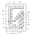
図1は本発明に係るシール部材付き転がり軸受ユニットの一実施形態を説明するための断面図、図2は図1のA部拡大図、図3は図2のシール部材を説明するための要部拡大図、図4は本発明例及び従来例におけるしめしろとトルク比との関係を示すグラフ図、図5はシール部材の第1変形例を説明するための断面図、図6はシール部材の第2変形例を説明するための断面図である。
例えば、アキシアルリップは、その先端が斜部に接触していればよく、その形状は任意であり、特に限定するものではない。
また、本実施形態では、シールリップにアキシアルリップを1つ設ける場合を例示したが、これに限定されず、アキシアルリップを複数個設けて、このアキシアルリップの数に対応する複数の斜部をスリンガに設けてもよい。
また、本実施形態では、転動体として玉を使用しているが、これに限定されず、円筒ころ、円すいころ及び針状ころ等を使用してもよい。
また、本実施形態では、内輪回転の駆動輪用の転がり軸受ユニットに本発明を適用した場合を例示したが、これに代えて、内輪回転の従動輪用の転がり軸受ユニットや、外輪回転の従動輪用及び駆動輪用の転がり軸受ユニットに本発明を適用してもよい。
さらに、本実施形態では、転がり軸受ユニットのシール部材に本発明を適用した場合を例示したが、転がり軸受のシール部材に本発明を適用してもよい。
2 外輪(静止輪)
3 ハブ輪(回転輪)
4 内輪(回転輪)
5 玉(転動体)
6 保持器
8 ナックル
11,12 シール部材
15 芯金
16 スリンガ(シールリップ相手部材)
16a 円筒部
16b 内側円環部
16c 斜部
16d 外側円環部
17 シールリップ
17a アキシアルリップ
17b ラジアルリップ
17c 内側リップ
19,20 ラビリンスリール
Claims (2)
- 1又は複数のシールリップと、前記シールリップの少なくとも1つが摺接するシールリップ相手部材と、を備えるシール部材であって、
前記シールリップ相手部材はスリンガであり、前記スリンガに軸方向外側に傾斜する斜部を設け、
前記シールリップの少なくとも1つは径方向外方に向けて斜めに立ち上がるように形成されるアキシアルリップであり、
前記斜部に前記アキシアルリップの先端を摺接させ、且つ
前記アキシアルリップの根元から立ち上がる部分と軸とのなす角度である立ち上がり角度は、前記斜部と軸とのなす角度である傾斜角度よりも大きく、
前記斜部は、軸方向で前記スリンガを、前記アキシアルリップとのしめしろが増大する方向に移動させることで描かれる前記アキシアルリップの先端と前記斜部との接触点の円弧状の軌跡で、設定した接触点での接線に対して90°±15°となるように設定されることを特徴とするシール部材。 - 少なくとも一つの軌道面が形成される静止輪と、少なくとも一つの軌道面が形成される回転輪と、前記静止輪及び前記回転輪の両軌道面の間に転動自在に配置される複数の転動体と、を備え、
前記静止輪及び前記回転輪の軸方向端部に請求項1記載のシール部材を設けることを特徴とするシール部材付き転がり軸受ユニット。
Priority Applications (1)
| Application Number | Priority Date | Filing Date | Title |
|---|---|---|---|
| JP2005168203A JP4654779B2 (ja) | 2005-06-08 | 2005-06-08 | シール部材及びシール部材付き転がり軸受ユニット |
Applications Claiming Priority (1)
| Application Number | Priority Date | Filing Date | Title |
|---|---|---|---|
| JP2005168203A JP4654779B2 (ja) | 2005-06-08 | 2005-06-08 | シール部材及びシール部材付き転がり軸受ユニット |
Publications (3)
| Publication Number | Publication Date |
|---|---|
| JP2006342871A JP2006342871A (ja) | 2006-12-21 |
| JP2006342871A5 JP2006342871A5 (ja) | 2008-05-15 |
| JP4654779B2 true JP4654779B2 (ja) | 2011-03-23 |
Family
ID=37639981
Family Applications (1)
| Application Number | Title | Priority Date | Filing Date |
|---|---|---|---|
| JP2005168203A Expired - Fee Related JP4654779B2 (ja) | 2005-06-08 | 2005-06-08 | シール部材及びシール部材付き転がり軸受ユニット |
Country Status (1)
| Country | Link |
|---|---|
| JP (1) | JP4654779B2 (ja) |
Families Citing this family (10)
| Publication number | Priority date | Publication date | Assignee | Title |
|---|---|---|---|---|
| JP2009103142A (ja) * | 2007-10-19 | 2009-05-14 | Toyota Motor Corp | シール装置 |
| JP5303909B2 (ja) * | 2007-11-20 | 2013-10-02 | 株式会社ジェイテクト | 密封装置、転がり軸受および車輪用転がり軸受 |
| JP5327603B2 (ja) * | 2008-08-05 | 2013-10-30 | 株式会社ジェイテクト | 転がり軸受装置 |
| JP6490348B2 (ja) * | 2014-03-31 | 2019-03-27 | Ntn株式会社 | プーリユニット |
| JP2016044687A (ja) * | 2014-08-19 | 2016-04-04 | キーパー株式会社 | オイルシール |
| JP6864624B2 (ja) | 2015-09-25 | 2021-04-28 | Nok株式会社 | ディファレンシャル機構用密封装置 |
| KR20200023459A (ko) * | 2017-07-07 | 2020-03-04 | 엔오케이 가부시키가이샤 | 밀봉장치 |
| JP6890488B2 (ja) * | 2017-07-07 | 2021-06-18 | Nok株式会社 | 密封装置 |
| JP6896536B2 (ja) * | 2017-07-07 | 2021-06-30 | Nok株式会社 | 密封装置 |
| JP6852657B2 (ja) * | 2017-11-20 | 2021-03-31 | トヨタ自動車株式会社 | シール装置 |
Citations (2)
| Publication number | Priority date | Publication date | Assignee | Title |
|---|---|---|---|---|
| JP2002372059A (ja) * | 2001-06-12 | 2002-12-26 | Nsk Ltd | 軸受装置 |
| JP2004068844A (ja) * | 2002-08-02 | 2004-03-04 | Nsk Ltd | シールリング及びシールリング付転がり軸受ユニット |
-
2005
- 2005-06-08 JP JP2005168203A patent/JP4654779B2/ja not_active Expired - Fee Related
Patent Citations (2)
| Publication number | Priority date | Publication date | Assignee | Title |
|---|---|---|---|---|
| JP2002372059A (ja) * | 2001-06-12 | 2002-12-26 | Nsk Ltd | 軸受装置 |
| JP2004068844A (ja) * | 2002-08-02 | 2004-03-04 | Nsk Ltd | シールリング及びシールリング付転がり軸受ユニット |
Also Published As
| Publication number | Publication date |
|---|---|
| JP2006342871A (ja) | 2006-12-21 |
Similar Documents
| Publication | Publication Date | Title |
|---|---|---|
| JP4654779B2 (ja) | シール部材及びシール部材付き転がり軸受ユニット | |
| JP5334287B2 (ja) | ベアリングシール | |
| WO2010113842A1 (ja) | 環状密封装置 | |
| US9976600B2 (en) | Method of producing wheel bearing apparatus | |
| CN211778585U (zh) | 轮毂单元轴承 | |
| JP4822173B2 (ja) | 車両用ハブユニット | |
| JP5087901B2 (ja) | 車輪用転がり軸受装置 | |
| JP5733080B2 (ja) | 転がり軸受 | |
| JP2005119505A (ja) | 車輪用軸受装置 | |
| JP4333116B2 (ja) | 転がり軸受の密封装置 | |
| JP2005059830A (ja) | 車輪用軸受装置 | |
| JP2008144861A (ja) | 軸受ユニット | |
| JP4531541B2 (ja) | 密封装置 | |
| JP7119992B2 (ja) | ハブユニット軸受 | |
| JP2005059832A (ja) | 車両用軸受装置 | |
| WO2020145244A1 (ja) | 転がり軸受 | |
| JP4042528B2 (ja) | 転がり軸受装置 | |
| JP2012087901A (ja) | 密封装置および転がり軸受装置 | |
| JP5202348B2 (ja) | センサ付車輪用軸受装置 | |
| JP4748003B2 (ja) | ドラムブレーキ装置のシール構造 | |
| WO2023189756A1 (ja) | 車輪用軸受装置 | |
| JP2013029132A (ja) | 転がり軸受 | |
| JP7273963B2 (ja) | 密封装置、密封構造および密封構造の固定方法 | |
| JP5834551B2 (ja) | 転がり軸受の製造方法 | |
| JP4560989B2 (ja) | 密封装置ならびに車軸用軸受装置 |
Legal Events
| Date | Code | Title | Description |
|---|---|---|---|
| RD04 | Notification of resignation of power of attorney |
Free format text: JAPANESE INTERMEDIATE CODE: A7424 Effective date: 20071128 |
|
| A521 | Written amendment |
Free format text: JAPANESE INTERMEDIATE CODE: A523 Effective date: 20080402 |
|
| A621 | Written request for application examination |
Free format text: JAPANESE INTERMEDIATE CODE: A621 Effective date: 20080402 |
|
| A977 | Report on retrieval |
Free format text: JAPANESE INTERMEDIATE CODE: A971007 Effective date: 20100714 |
|
| A131 | Notification of reasons for refusal |
Free format text: JAPANESE INTERMEDIATE CODE: A131 Effective date: 20100727 |
|
| A521 | Written amendment |
Free format text: JAPANESE INTERMEDIATE CODE: A523 Effective date: 20100914 |
|
| TRDD | Decision of grant or rejection written | ||
| A01 | Written decision to grant a patent or to grant a registration (utility model) |
Free format text: JAPANESE INTERMEDIATE CODE: A01 Effective date: 20101124 |
|
| A01 | Written decision to grant a patent or to grant a registration (utility model) |
Free format text: JAPANESE INTERMEDIATE CODE: A01 |
|
| A61 | First payment of annual fees (during grant procedure) |
Free format text: JAPANESE INTERMEDIATE CODE: A61 Effective date: 20101207 |
|
| FPAY | Renewal fee payment (event date is renewal date of database) |
Free format text: PAYMENT UNTIL: 20140107 Year of fee payment: 3 |
|
| R150 | Certificate of patent or registration of utility model |
Free format text: JAPANESE INTERMEDIATE CODE: R150 |
|
| LAPS | Cancellation because of no payment of annual fees |