JP4654779B2 - Seal member and rolling bearing unit with seal member - Google Patents
Seal member and rolling bearing unit with seal member Download PDFInfo
- Publication number
- JP4654779B2 JP4654779B2 JP2005168203A JP2005168203A JP4654779B2 JP 4654779 B2 JP4654779 B2 JP 4654779B2 JP 2005168203 A JP2005168203 A JP 2005168203A JP 2005168203 A JP2005168203 A JP 2005168203A JP 4654779 B2 JP4654779 B2 JP 4654779B2
- Authority
- JP
- Japan
- Prior art keywords
- lip
- seal
- seal member
- axial
- slinger
- Prior art date
- Legal status (The legal status is an assumption and is not a legal conclusion. Google has not performed a legal analysis and makes no representation as to the accuracy of the status listed.)
- Expired - Fee Related
Links
Images


Classifications
-
- F—MECHANICAL ENGINEERING; LIGHTING; HEATING; WEAPONS; BLASTING
- F16—ENGINEERING ELEMENTS AND UNITS; GENERAL MEASURES FOR PRODUCING AND MAINTAINING EFFECTIVE FUNCTIONING OF MACHINES OR INSTALLATIONS; THERMAL INSULATION IN GENERAL
- F16C—SHAFTS; FLEXIBLE SHAFTS; ELEMENTS OR CRANKSHAFT MECHANISMS; ROTARY BODIES OTHER THAN GEARING ELEMENTS; BEARINGS
- F16C33/00—Parts of bearings; Special methods for making bearings or parts thereof
- F16C33/72—Sealings
- F16C33/76—Sealings of ball or roller bearings
- F16C33/78—Sealings of ball or roller bearings with a diaphragm, disc, or ring, with or without resilient members
- F16C33/7869—Sealings of ball or roller bearings with a diaphragm, disc, or ring, with or without resilient members mounted with a cylindrical portion to the inner surface of the outer race and having a radial portion extending inward
- F16C33/7879—Sealings of ball or roller bearings with a diaphragm, disc, or ring, with or without resilient members mounted with a cylindrical portion to the inner surface of the outer race and having a radial portion extending inward with a further sealing ring
-
- F—MECHANICAL ENGINEERING; LIGHTING; HEATING; WEAPONS; BLASTING
- F16—ENGINEERING ELEMENTS AND UNITS; GENERAL MEASURES FOR PRODUCING AND MAINTAINING EFFECTIVE FUNCTIONING OF MACHINES OR INSTALLATIONS; THERMAL INSULATION IN GENERAL
- F16C—SHAFTS; FLEXIBLE SHAFTS; ELEMENTS OR CRANKSHAFT MECHANISMS; ROTARY BODIES OTHER THAN GEARING ELEMENTS; BEARINGS
- F16C2326/00—Articles relating to transporting
- F16C2326/01—Parts of vehicles in general
- F16C2326/02—Wheel hubs or castors
Description
本発明は、シール部材及びシール部材付き転がり軸受ユニットに関するものであり、特に、自動車等の車輪を支持するのに好適なシール部材付き転がり軸受ユニットに関する。 The present invention relates to a seal member and a rolling bearing unit with a seal member, and more particularly to a rolling bearing unit with a seal member suitable for supporting a wheel of an automobile or the like.
従来、この種のシール部材付き転がり軸受ユニットとしては、例えば、図7に示すようなシール部材付き転がり軸受ユニット100が知られている(例えば、特許文献1参照)。
Conventionally, as this type of rolling bearing unit with a seal member, for example, a rolling
特許文献1に記載のシール部材付き転がり軸受ユニット100は、図7に示すように、外輪102と、内輪に相当するハブ103と、複数個の転動体104,104とからなる。このうちのハブ103は、ハブ本体105と内輪素子106とを組み合わせてなる。また、各転動体104,104は、外輪102の内周面に形成した複列の外輪軌道面102a,102aと、ハブ103の外周面に形成した内輪軌道面103a,103aとの間に、それぞれ複数個ずつ転動自在に設けている。そして、車両の懸架装置に車輪を回転自在に支持する際には、外輪102を懸架装置を構成するナックル107に固定すると共に、ハブ本体105に設けた取付フランジ108に車輪を固定する。
As shown in FIG. 7, the rolling
また、シール部材付き転がり軸受ユニット100は、外輪102のインボード側端部と内輪素子106との間、及び外輪102のアウトボード側端部とハブ本体105との間に、シール部材109,110をそれぞれ設けている。これにより、転がり軸受ユニット100内に封入したグリースが外部に漏洩することを防止すると共に、外部に存在する雨水、泥、塵等の各種異物が転がり軸受ユニット100内に浸入することを防止している。
Further, the rolling
シール部材109は、図8に示すように、外輪102のインボード側端部の内周面に嵌合される芯金111と、内輪素子106の外周面に嵌合されるスリンガ112と、芯金111に接着等により固定され、スリンガ112に摺接するシールリップ113と、を備えている。シールリップ113は、図示の例では、スリンガ112に対して軸方向に摺接するアキシアルリップ114と、径方向に摺接するラジアルリップ115と、を有している。
As shown in FIG. 8, the
シール部材110は、図7に示すように、外輪102のアウトボード側端部の内周面に嵌合される芯金116と、芯金116に接着等により固定され、ハブ本体105の外周面に摺接するシールリップ117と、を備えている。
As shown in FIG. 7, the
ところで、一般的に、シール部材により転がり軸受ユニットの密封性を確保するためには、シールリップとシールリップ相手部材(スリンガ112、ハブ本体105)とのしめしろを大きくしたほうが効果的であるが、その反面、トルクが大きくなるので、従来においては、密封性を確保すると共に、低トルク化を図るために、しめしろの最適化を図っていた。
By the way, in general, in order to ensure the sealing performance of the rolling bearing unit by the seal member, it is more effective to increase the interference between the seal lip and the seal lip mating member (
しかしながら、シール部材付き転がり軸受ユニット100では、しめしろの最適化は図られているものの、トルク変動(バラツキ)の面が考慮されておらず、シールリップ113とスリンガ112とのしめしろが寸法公差(組み付け誤差)の範囲内で変化するため、トルク変動が発生してしまう。つまり、シール部材の低トルク化も重要であるが、トルク変動を抑制することも重要な要素となる。
However, in the rolling
また、シールリップ113とスリンガ112とのしめしろが不適切になるのは、車両の走行時における各部の弾性変形によっても生じる。即ち、車両の旋回時に車輪を構成するタイヤの接地面から取り付けフランジ108を介してハブ103に加わるモーメントM(図7参照)に基づく転がり軸受ユニット100の構成各部材の弾性変形により、ハブ103の中心軸が中立状態から角度λ分だけ変位して、図8に示すように、シールリップ113とスリンガ112との摺接状態が円周方向に関して不均一になるみそすり運動(軸方向及び径方向への運動)が発生する。これにより、しめしろが変化するため、トルク変動が発生してしまう。
Further, the inappropriate interference between the
本発明は、このような不都合を解消するためになされたものであり、その目的は、シールリップとシールリップ相手部材とのしめしろが変化したとしても、密封性を確保することができ、トルク変動を抑制することができるシール部材及びシール部材付き転がり軸受ユニットを提供することにある。 The present invention has been made to eliminate such inconveniences, and the purpose of the present invention is to ensure sealing performance even if the interference between the seal lip and the seal lip mating member changes, and to provide torque. An object of the present invention is to provide a seal member and a rolling bearing unit with a seal member that can suppress fluctuations.
本発明の上記目的は、下記の構成により達成される。
(1) 1又は複数のシールリップと、前記シールリップの少なくとも1つが摺接するシールリップ相手部材と、を備えるシール部材であって、前記シールリップ相手部材はスリンガであり、前記スリンガに軸方向外側に傾斜する斜部を設け、前記シールリップの少なくとも1つは径方向外方に向けて斜めに立ち上がるように形成されるアキシアルリップであり、前記斜部に前記アキシアルリップの先端を摺接させ、且つ前記アキシアルリップの根元から立ち上がる部分と軸とのなす角度である立ち上がり角度は、前記斜部と軸とのなす角度である傾斜角度よりも大きく、前記斜部は、軸方向で前記スリンガを前記アキシアルリップとのしめしろが増大する方向に移動させることで描かれる前記アキシアルリップの先端と前記斜部との接触点の円弧状の軌跡で、設定した接触点での接線に対して90°±15°となるように設定されることを特徴とするシール部材。
(2) 少なくとも一つの軌道面が形成される静止輪と、少なくとも一つの軌道面が形成される回転輪と、静止輪及び回転輪の両軌道面の間に転動自在に配置される複数の転動体と、を備え、静止輪及び回転輪の軸方向端部に(1)に記載のシール部材を設けることを特徴とするシール部材付き転がり軸受ユニット。
The above object of the present invention can be achieved by the following constitution.
(1) A seal member including one or a plurality of seal lips and a seal lip mating member in which at least one of the seal lips is in sliding contact, wherein the seal lip mating member is a slinger, and the slinger is axially disposed in the axial direction. An inclined portion that is inclined outward is provided, and at least one of the seal lips is an axial lip formed so as to rise obliquely outward in the radial direction, and the tip of the axial lip is slidably contacted with the inclined portion. And the rising angle, which is the angle formed by the portion rising from the base of the axial lip and the shaft, is greater than the tilt angle, which is the angle formed by the inclined portion and the shaft, and the inclined portion causes the slinger to move in the axial direction. The contact point between the tip of the axial lip and the oblique portion drawn by moving in the direction in which the interference with the axial lip increases A seal member characterized by being set to be 90 ° ± 15 ° with respect to a tangent at a set contact point in an arc-shaped locus .
(2) A stationary wheel on which at least one raceway surface is formed, a rotating wheel on which at least one raceway surface is formed, and a plurality of rolling wheels disposed between both raceway surfaces of the stationary wheel and the rotating wheel. A rolling bearing unit with a seal member, wherein the seal member according to (1) is provided at axial ends of the stationary wheel and the rotating wheel.
本発明のシール部材及びシール部材付き転がり軸受ユニットによれば、シールリップ相手部材はスリンガであり、スリンガに軸方向外側に傾斜する斜部を設け、斜部にシールリップの先端を摺接させるため、シールリップとシールリップ相手部材とのしめしろが変化したとしても、密封性を確保することができ、トルク変動を抑制することができる。 According to the seal member and the rolling bearing unit with the seal member of the present invention, the seal lip mating member is a slinger, and the slinger is provided with a slanted portion that is inclined outward in the axial direction, and the tip of the seal lip is slidably contacted with the slanted portion. Even if the interference between the seal lip and the seal lip mating member changes, the sealing performance can be ensured and the torque fluctuation can be suppressed.
以下、本発明に係るシール部材及びシール部材付き転がり軸受ユニットの一実施形態を説明するために、シール部材付き転がり軸受ユニットについて、図面を参照して詳細に説明する。
図1は本発明に係るシール部材付き転がり軸受ユニットの一実施形態を説明するための断面図、図2は図1のA部拡大図、図3は図2のシール部材を説明するための要部拡大図、図4は本発明例及び従来例におけるしめしろとトルク比との関係を示すグラフ図、図5はシール部材の第1変形例を説明するための断面図、図6はシール部材の第2変形例を説明するための断面図である。
Hereinafter, in order to describe one embodiment of a seal member and a rolling bearing unit with a seal member according to the present invention, a rolling bearing unit with a seal member will be described in detail with reference to the drawings.
FIG. 1 is a cross-sectional view for explaining an embodiment of a rolling bearing unit with a seal member according to the present invention, FIG. 2 is an enlarged view of a portion A in FIG. 1, and FIG. FIG. 4 is a graph showing the relationship between interference and torque ratio in the present invention example and the conventional example, FIG. 5 is a cross-sectional view for explaining a first modification of the seal member, and FIG. 6 is a seal member. It is sectional drawing for demonstrating the 2nd modification of this.
本実施形態のシール部材付き転がり軸受ユニット1は、図1に示すように、静止輪である外輪2と、回転輪であるハブ輪3及び内輪4と、複数の転動体である玉5と、玉5を円周方向に等間隔に保持する一対の保持器6,6と、を備えている。なお、図中7は、外輪2のインボード側端部に外嵌固定されるハブキャップである。
As shown in FIG. 1, the rolling
外輪2は、懸架装置を構成するナックル8に形成される保持孔8aに内嵌され、外輪2の外周面に設けられる懸架用フランジ9をナックル8にボルト締結することによって、ナックル8に結合固定される。また、外輪2の内周面には、2列の外輪軌道面2a,2aが形成され、一方、ハブ輪3及び内輪4の外周面には、外輪2の外輪軌道面2a,2aに対応する1列の内輪軌道面3a,4aがそれぞれ形成されており、これら両軌道面2a,2a,3a,4aの間に玉5が転動自在に配置されている。
The
ハブ輪3のインボード側端部には、小径段部3bが形成されており、内輪4は、この小径段部3bに外嵌され、ハブ輪3のインボード側端部を径方向外方に加締め広げた加締め部3cによって、ハブ輪3に結合固定される。また、加締め部3cによって内輪4を押圧することで、適正な与圧が付与されている。
A small-
また、ハブ輪3は、そのアウトボード側端部の外周面に径方向外方に延びるフランジ3dを有しており、このフランジ3dには、不図示のホイール及びブレーキロータ等を締結するためのハブボルト10が周方向に略等間隔で複数植設されている。
Further, the
そして、外輪2のアウトボード側端部とハブ輪3との間には、シール部材11が設けられ、外輪2のインボード側端部と内輪4との間には、シール部材12が設けられる。これにより、転がり軸受ユニット1の軸受空間の軸方向両端部をシールして、封入したグリースが外部に漏洩することを防止すると共に、外部に存在する雨水、泥、塵等の各種異物が軸受空間内に浸入することを防止している。
A
シール部材11は、外輪2のアウトボード側端部の内周面に嵌合される芯金13と、この芯金13に接着固定されてハブ輪3のフランジ3dの内側面(図1の右側面)と摺接するシールリップ14と、を備えている。
The
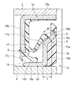
シール部材12は、図2に示すように、外輪2のインボード側端部の内周面に嵌合される芯金15と、内輪4のインボード側端部の外周面に嵌合されるスリンガ16(シールリップ相手部材)と、芯金15に接着固定されてスリンガ16と摺接するシールリップ17と、を備えている。
As shown in FIG. 2, the
芯金15は、外輪2の内周面に内嵌固定される円筒部15aと、この円筒部15aの軸方向内端縁(図2の左端縁)から径方向内方に延びる環状のフランジ部15bと、を有して、断面略L字状に形成される。
The
スリンガ16は、内輪4の外周面に外嵌固定される円筒部16aと、この円筒部16aの軸方向外端縁(図2の右側縁)から径方向外方に延びる内側円環部16bと、内側円環部16bの外周縁部から軸方向外方及び径方向外方に向けて斜めに延びる斜部16cと、斜部16cの外周縁部から径方向外方に延びる外側円環部16dと、を有している。また、スリンガ16の外側面、即ち、内側円環部16b、斜部16c及び外側円環部16dの軸方向外側面(図2の右側面)には、例えば、車両のABS用のセンサ等として使用される磁気エンコーダ18が接着等により固定されている。
The
シールリップ17は、ゴム材料によって形成され、芯金15の円筒部15a及びフランジ部15bに接着固定される。また、シールリップ17は、スリンガ16の斜部16cに対して軸方向に摺接するアキシアルリップ17aと、スリンガ16の円筒部16aの外周面に対して径方向に摺接するラジアルリップ17bと、スリンガ16の円筒部16aの外周面との間にラビリンスシール19を形成する内側リップ17cと、を有している。
The
斜部16cは、スリンガ16をアキシアルリップ17aとのしめしろが増大する方向(図2の左方向)に移動させることで描かれるアキシアルリップ17aの先端と斜部16cとの接触点の円弧状の軌跡Sにおいて、設定した接触点での接線Tに対して90°の角度となるように設定される。
The
このように構成されるシール部材12では、図2に示すように、スリンガ16とシールリップ17とをパッキングする際に、スリンガ16が軸方向動き量(しめしろ)δ分だけ移動する。この時、シールリップ17のアキシアルリップ17aの先端は、スリンガ16の斜部16cに接触し、押圧されて、支点Xを中心にして、破線から実線へと円弧を描くように移動する。
In the sealing
図2の状態をさらに詳述すると、図3に示すように、スリンガ16に接触する前のアキシアルリップ17aの先端位置はQ’点にある。そして、スリンガ16を軸方向動き量δだけ押し込んでいくと、アキシアルリップ17aの先端位置はQ’点からP’点へと移動する。
2 will be described in more detail. As shown in FIG. 3, the tip position of the
ここで、従来の平面状のスリンガ(A−A線)を使用した場合を説明すると、スリンガを軸方向動き量δだけ押し込んでいくと、アキシアルリップ17aの先端位置は、Q’点からP’’点まで移動する。シールリップ17の長さに対して軸方向動き量δは十分に小さいので、アキシアルリップ17aの先端が描く円弧状の軌跡(曲線)は、線分PQとして近似できる。
Here, the case where a conventional planar slinger (A-A line) is used will be described. When the slinger is pushed in by the axial movement amount δ, the tip position of the
そして、平面状スリンガを使用した場合のアキシアルリップ17aの先端移動量PQは、PQ=O’Q/sinθとなり、本実施形態のスリンガ16を使用した場合のアキシアルリップ17aの先端移動量はP’Qは、P’Q=O’Q・sinθとなる。従って、P’Q=PQ・sin2θとなる。即ち、本実施形態のスリンガ16の方が、従来の平面状のスリンガよりもアキシアルリップ17aの先端移動量がsin2θ分だけ小さくなる。
The tip movement amount PQ of the
これにより、組み付け誤差やみそすり運動等によって、シールリップ17とスリンガ16とのしめしろが変化したとしても、アキシアルリップ17aの先端移動量を小さくすることができるので、アキシアルリップ17aに与えるしめしろの変化の影響を最低限に抑えることができる。この結果、転がり軸受ユニット1の密封性を確保することができ、トルク変動(ばらつき)を抑制することができる。
As a result, even if the interference between the
また、本実施形態では、アキシアルリップ17aの根元にくびれを設け、先端に向かうに従って肉厚が漸増するようにアキシアルリップ17aを形成している。これは、アキシアルリップ17aの変形を根元に設けたくびれにある程度集中させることによって、しめしろの変化がアキシアルリップ17aに与える影響を低減するためである。なお、本実施形態では、アキシアルリップ17aの根元にくびれを設けているが、アキシアルリップ17aの形状は、本発明を達成できるものであれば任意であり、特に限定されない。
Further, in the present embodiment, a constriction is provided at the base of the
また、一般的に、設計上のしめしろは、シール部材12の作製精度や、組み付け誤差及びみそすり運動によるしめしろの変化等を考慮して、ある程度の範囲をもっている。この範囲を考慮すると、本実施形態のスリンガ16の斜部16cに対して±15°の許容範囲を設けることができる。即ち、本実施形態の接線Tに対して90°±15°の角度となるように斜部16cを設定することができ、この場合も上記と同様の効果を得ることができる。
In general, the design interference has a certain range in consideration of the manufacturing accuracy of the
図4は、本発明例及び従来例におけるしめしろとトルク比との関係を示すグラフ図である。このグラフ図は、しめしろが公差中央時のトルクを1とした場合の公差上限時と公差下限時とのトルク比を示している。 FIG. 4 is a graph showing the relationship between the interference and the torque ratio in the present invention example and the conventional example. This graph shows the torque ratio between the upper limit of tolerance and the lower limit of tolerance when the torque at the center of tolerance is 1.
図4から明らかなように、本実施例がトルク比0.8〜1.16の範囲でトルク変動しているのに対して、従来例はトルク比0.62〜1.28の範囲でトルク変動していることから、本実施例の方が、従来例よりもトルク値が安定しており、トルク変動が抑制されているのがわかった。 As is apparent from FIG. 4, the torque fluctuates in the range of the torque ratio of 0.8 to 1.16 in the present example, whereas the torque of the conventional example is in the range of the torque ratio of 0.62 to 1.28. Since it fluctuated, it was found that the torque value in this example was more stable than that in the conventional example, and the torque fluctuation was suppressed.
従って、本実施形態のシール部材付き転がり軸受ユニット1によれば、スリンガ16に軸方向外側に傾斜する斜部16cを設け、斜部16cにシールリップ17のアキシアルリップ17aの先端を摺接させるため、シールリップ17とスリンガ16とのしめしろが変化したとしても、密封性を確保することができ、トルク変動を抑制することができる。
Therefore, according to the rolling bearing unit with a
なお、本実施形態の第1変形例として、シール部材12は、図5に示すように、内側円環部16b及び斜部16cの軸方向外側面を外側円環部16dの軸方向外側面と面一になるように形成、即ち、スリンガ16の軸方向外側面を平面状に形成して、その外側面に磁気エンコーダ18を接着等により固定するようにしてもよい。
As a first modification of the present embodiment, as shown in FIG. 5, the
また、本実施形態の第2変形例として、シール部材12は、図6に示すように、スリンガ16の軸方向外側面に磁気エンコーダ18を設けなくてもよい。この場合、外側円環部16dを径方向外方に延ばし、その外周縁部を芯金15の円筒部15aの内周面に近接させて、外側円環部16dと円筒部15aとの間にラビリンスシール20を形成する。
As a second modification of the present embodiment, the
なお、本発明は、本実施形態に限定されるものでなく、本発明の要旨を逸脱しない範囲において適宜変更可能である。
例えば、アキシアルリップは、その先端が斜部に接触していればよく、その形状は任意であり、特に限定するものではない。
また、本実施形態では、シールリップにアキシアルリップを1つ設ける場合を例示したが、これに限定されず、アキシアルリップを複数個設けて、このアキシアルリップの数に対応する複数の斜部をスリンガに設けてもよい。
また、本実施形態では、転動体として玉を使用しているが、これに限定されず、円筒ころ、円すいころ及び針状ころ等を使用してもよい。
また、本実施形態では、内輪回転の駆動輪用の転がり軸受ユニットに本発明を適用した場合を例示したが、これに代えて、内輪回転の従動輪用の転がり軸受ユニットや、外輪回転の従動輪用及び駆動輪用の転がり軸受ユニットに本発明を適用してもよい。
さらに、本実施形態では、転がり軸受ユニットのシール部材に本発明を適用した場合を例示したが、転がり軸受のシール部材に本発明を適用してもよい。
In addition, this invention is not limited to this embodiment, In the range which does not deviate from the summary of this invention, it can change suitably.
For example, the axial lip may be any shape as long as the tip thereof is in contact with the oblique portion, and the shape thereof is not particularly limited.
In this embodiment, the case where one axial lip is provided on the seal lip is exemplified, but the present invention is not limited to this. A plurality of axial lips are provided, and a plurality of oblique portions corresponding to the number of the axial lips are provided as slinger. May be provided.
In the present embodiment, balls are used as the rolling elements, but the present invention is not limited thereto, and cylindrical rollers, tapered rollers, needle rollers, and the like may be used.
Further, in the present embodiment, the case where the present invention is applied to the rolling bearing unit for the driving wheel for inner ring rotation is exemplified, but instead, the rolling bearing unit for the driven wheel for inner ring rotation or the driven bearing for outer ring rotation is used. The present invention may be applied to rolling bearing units for driving wheels and driving wheels.
Furthermore, although the case where this invention was applied to the sealing member of a rolling bearing unit was illustrated in this embodiment, you may apply this invention to the sealing member of a rolling bearing.
1 シール部材付き転がり軸受ユニット
2 外輪(静止輪)
3 ハブ輪(回転輪)
4 内輪(回転輪)
5 玉(転動体)
6 保持器
8 ナックル
11,12 シール部材
15 芯金
16 スリンガ(シールリップ相手部材)
16a 円筒部
16b 内側円環部
16c 斜部
16d 外側円環部
17 シールリップ
17a アキシアルリップ
17b ラジアルリップ
17c 内側リップ
19,20 ラビリンスリール
1 Rolling bearing unit with
3 Hub wheel (rotating wheel)
4 Inner ring (rotating wheel)
5 balls (rolling elements)
6 Cage 8
16a
Claims (2)
前記シールリップ相手部材はスリンガであり、前記スリンガに軸方向外側に傾斜する斜部を設け、
前記シールリップの少なくとも1つは径方向外方に向けて斜めに立ち上がるように形成されるアキシアルリップであり、
前記斜部に前記アキシアルリップの先端を摺接させ、且つ
前記アキシアルリップの根元から立ち上がる部分と軸とのなす角度である立ち上がり角度は、前記斜部と軸とのなす角度である傾斜角度よりも大きく、
前記斜部は、軸方向で前記スリンガを、前記アキシアルリップとのしめしろが増大する方向に移動させることで描かれる前記アキシアルリップの先端と前記斜部との接触点の円弧状の軌跡で、設定した接触点での接線に対して90°±15°となるように設定されることを特徴とするシール部材。 A seal member comprising one or more seal lips and a seal lip mating member with which at least one of the seal lips comes into sliding contact,
The seal lip mating member is a slinger, and the slinger is provided with an inclined portion that is inclined outward in the axial direction.
At least one of the seal lips is an axial lip formed so as to rise obliquely outward in the radial direction;
The tip of the axial lip is brought into sliding contact with the oblique portion, and
The rising angle, which is the angle formed by the portion rising from the base of the axial lip and the axis, is greater than the inclination angle, which is the angle formed by the oblique portion and the axis,
The oblique portion is an arcuate locus of a contact point between the tip end of the axial lip and the oblique portion drawn by moving the slinger in the axial direction in a direction in which the interference with the axial lip increases. A seal member characterized by being set to be 90 ° ± 15 ° with respect to a tangent at a set contact point .
前記静止輪及び前記回転輪の軸方向端部に請求項1記載のシール部材を設けることを特徴とするシール部材付き転がり軸受ユニット。 A stationary wheel on which at least one raceway surface is formed, a rotating wheel on which at least one raceway surface is formed, and a plurality of rolling wheels disposed between the stationary wheels and the raceway surfaces of the rotating wheel so as to be capable of rolling. A moving body,
A rolling bearing unit with a seal member, wherein the seal member according to claim 1 is provided at axial ends of the stationary wheel and the rotating wheel.
Priority Applications (1)
| Application Number | Priority Date | Filing Date | Title |
|---|---|---|---|
| JP2005168203A JP4654779B2 (en) | 2005-06-08 | 2005-06-08 | Seal member and rolling bearing unit with seal member |
Applications Claiming Priority (1)
| Application Number | Priority Date | Filing Date | Title |
|---|---|---|---|
| JP2005168203A JP4654779B2 (en) | 2005-06-08 | 2005-06-08 | Seal member and rolling bearing unit with seal member |
Publications (3)
| Publication Number | Publication Date |
|---|---|
| JP2006342871A JP2006342871A (en) | 2006-12-21 |
| JP2006342871A5 JP2006342871A5 (en) | 2008-05-15 |
| JP4654779B2 true JP4654779B2 (en) | 2011-03-23 |
Family
ID=37639981
Family Applications (1)
| Application Number | Title | Priority Date | Filing Date |
|---|---|---|---|
| JP2005168203A Expired - Fee Related JP4654779B2 (en) | 2005-06-08 | 2005-06-08 | Seal member and rolling bearing unit with seal member |
Country Status (1)
| Country | Link |
|---|---|
| JP (1) | JP4654779B2 (en) |
Families Citing this family (10)
| Publication number | Priority date | Publication date | Assignee | Title |
|---|---|---|---|---|
| JP2009103142A (en) * | 2007-10-19 | 2009-05-14 | Toyota Motor Corp | Sealing device |
| JP5303909B2 (en) * | 2007-11-20 | 2013-10-02 | 株式会社ジェイテクト | Sealing device, rolling bearing and wheel rolling bearing |
| JP5327603B2 (en) * | 2008-08-05 | 2013-10-30 | 株式会社ジェイテクト | Rolling bearing device |
| JP6490348B2 (en) * | 2014-03-31 | 2019-03-27 | Ntn株式会社 | Pulley unit |
| JP2016044687A (en) * | 2014-08-19 | 2016-04-04 | キーパー株式会社 | Oil seal |
| JP6864624B2 (en) * | 2015-09-25 | 2021-04-28 | Nok株式会社 | Sealing device for differential mechanism |
| KR20200023459A (en) * | 2017-07-07 | 2020-03-04 | 엔오케이 가부시키가이샤 | Sealing device |
| JP6890488B2 (en) * | 2017-07-07 | 2021-06-18 | Nok株式会社 | Sealing device |
| JP6896536B2 (en) * | 2017-07-07 | 2021-06-30 | Nok株式会社 | Sealing device |
| JP6852657B2 (en) * | 2017-11-20 | 2021-03-31 | トヨタ自動車株式会社 | Sealing device |
Citations (2)
| Publication number | Priority date | Publication date | Assignee | Title |
|---|---|---|---|---|
| JP2002372059A (en) * | 2001-06-12 | 2002-12-26 | Nsk Ltd | Bearing device |
| JP2004068844A (en) * | 2002-08-02 | 2004-03-04 | Nsk Ltd | Seal ring and rolling bearing unit with seal ring |
-
2005
- 2005-06-08 JP JP2005168203A patent/JP4654779B2/en not_active Expired - Fee Related
Patent Citations (2)
| Publication number | Priority date | Publication date | Assignee | Title |
|---|---|---|---|---|
| JP2002372059A (en) * | 2001-06-12 | 2002-12-26 | Nsk Ltd | Bearing device |
| JP2004068844A (en) * | 2002-08-02 | 2004-03-04 | Nsk Ltd | Seal ring and rolling bearing unit with seal ring |
Also Published As
| Publication number | Publication date |
|---|---|
| JP2006342871A (en) | 2006-12-21 |
Similar Documents
| Publication | Publication Date | Title |
|---|---|---|
| JP4654779B2 (en) | Seal member and rolling bearing unit with seal member | |
| JP5334287B2 (en) | Bearing seal | |
| WO2010113842A1 (en) | Annular sealing device | |
| US9976600B2 (en) | Method of producing wheel bearing apparatus | |
| CN211778585U (en) | Hub unit bearing | |
| JP4822173B2 (en) | Hub unit for vehicles | |
| JP5087901B2 (en) | Rolling bearing device for wheels | |
| JP5733080B2 (en) | Rolling bearing | |
| JP2005119505A (en) | Bearing device for wheel | |
| JP2005059830A (en) | Wheel bearing assembly | |
| JP2008144861A (en) | Bearing unit | |
| JP4531541B2 (en) | Sealing device | |
| JP7119992B2 (en) | hub unit bearing | |
| JP4333116B2 (en) | Rolling bearing sealing device | |
| WO2020145244A1 (en) | Rolling bearing | |
| JP4042528B2 (en) | Rolling bearing device | |
| JP2012087901A (en) | Sealing device and rolling bearing device | |
| JP2005059832A (en) | Wheel bearing assembly | |
| JP5202348B2 (en) | Bearing device for wheels with sensor | |
| JP4748003B2 (en) | Drum brake seal structure | |
| WO2023189756A1 (en) | Wheel bearing device | |
| JP2013029132A (en) | Rolling bearing | |
| JP7273963B2 (en) | Sealing device, sealing structure and method of fixing sealing structure | |
| JP5834551B2 (en) | Manufacturing method of rolling bearing | |
| JP4560989B2 (en) | Sealing device and axle bearing device |
Legal Events
| Date | Code | Title | Description |
|---|---|---|---|
| RD04 | Notification of resignation of power of attorney |
Free format text: JAPANESE INTERMEDIATE CODE: A7424 Effective date: 20071128 |
|
| A521 | Written amendment |
Free format text: JAPANESE INTERMEDIATE CODE: A523 Effective date: 20080402 |
|
| A621 | Written request for application examination |
Free format text: JAPANESE INTERMEDIATE CODE: A621 Effective date: 20080402 |
|
| A977 | Report on retrieval |
Free format text: JAPANESE INTERMEDIATE CODE: A971007 Effective date: 20100714 |
|
| A131 | Notification of reasons for refusal |
Free format text: JAPANESE INTERMEDIATE CODE: A131 Effective date: 20100727 |
|
| A521 | Written amendment |
Free format text: JAPANESE INTERMEDIATE CODE: A523 Effective date: 20100914 |
|
| TRDD | Decision of grant or rejection written | ||
| A01 | Written decision to grant a patent or to grant a registration (utility model) |
Free format text: JAPANESE INTERMEDIATE CODE: A01 Effective date: 20101124 |
|
| A01 | Written decision to grant a patent or to grant a registration (utility model) |
Free format text: JAPANESE INTERMEDIATE CODE: A01 |
|
| A61 | First payment of annual fees (during grant procedure) |
Free format text: JAPANESE INTERMEDIATE CODE: A61 Effective date: 20101207 |
|
| FPAY | Renewal fee payment (event date is renewal date of database) |
Free format text: PAYMENT UNTIL: 20140107 Year of fee payment: 3 |
|
| R150 | Certificate of patent or registration of utility model |
Free format text: JAPANESE INTERMEDIATE CODE: R150 |
|
| LAPS | Cancellation because of no payment of annual fees |