JP4021846B2 - 自動車のホイールリムにケーシングを取り付けるための装置及び関連する取り付け方法 - Google Patents
自動車のホイールリムにケーシングを取り付けるための装置及び関連する取り付け方法 Download PDFInfo
- Publication number
- JP4021846B2 JP4021846B2 JP2003526705A JP2003526705A JP4021846B2 JP 4021846 B2 JP4021846 B2 JP 4021846B2 JP 2003526705 A JP2003526705 A JP 2003526705A JP 2003526705 A JP2003526705 A JP 2003526705A JP 4021846 B2 JP4021846 B2 JP 4021846B2
- Authority
- JP
- Japan
- Prior art keywords
- casing
- rim
- sensor
- traction member
- stopper
- Prior art date
- Legal status (The legal status is an assumption and is not a legal conclusion. Google has not performed a legal analysis and makes no representation as to the accuracy of the status listed.)
- Expired - Fee Related
Links
- 238000000034 method Methods 0.000 title claims description 6
- 230000009471 action Effects 0.000 claims description 4
- 230000008859 change Effects 0.000 claims description 2
- 238000013459 approach Methods 0.000 description 1
- 238000003754 machining Methods 0.000 description 1
- 230000004048 modification Effects 0.000 description 1
- 238000012986 modification Methods 0.000 description 1
- 230000002028 premature Effects 0.000 description 1
- 238000007789 sealing Methods 0.000 description 1
Images


Classifications
-
- B—PERFORMING OPERATIONS; TRANSPORTING
- B60—VEHICLES IN GENERAL
- B60C—VEHICLE TYRES; TYRE INFLATION; TYRE CHANGING; CONNECTING VALVES TO INFLATABLE ELASTIC BODIES IN GENERAL; DEVICES OR ARRANGEMENTS RELATED TO TYRES
- B60C23/00—Devices for measuring, signalling, controlling, or distributing tyre pressure or temperature, specially adapted for mounting on vehicles; Arrangement of tyre inflating devices on vehicles, e.g. of pumps or of tanks; Tyre cooling arrangements
- B60C23/02—Signalling devices actuated by tyre pressure
- B60C23/04—Signalling devices actuated by tyre pressure mounted on the wheel or tyre
- B60C23/0491—Constructional details of means for attaching the control device
- B60C23/0494—Valve stem attachments positioned inside the tyre chamber
-
- B—PERFORMING OPERATIONS; TRANSPORTING
- B60—VEHICLES IN GENERAL
- B60C—VEHICLE TYRES; TYRE INFLATION; TYRE CHANGING; CONNECTING VALVES TO INFLATABLE ELASTIC BODIES IN GENERAL; DEVICES OR ARRANGEMENTS RELATED TO TYRES
- B60C23/00—Devices for measuring, signalling, controlling, or distributing tyre pressure or temperature, specially adapted for mounting on vehicles; Arrangement of tyre inflating devices on vehicles, e.g. of pumps or of tanks; Tyre cooling arrangements
- B60C23/02—Signalling devices actuated by tyre pressure
- B60C23/04—Signalling devices actuated by tyre pressure mounted on the wheel or tyre
- B60C23/0408—Signalling devices actuated by tyre pressure mounted on the wheel or tyre transmitting the signals by non-mechanical means from the wheel or tyre to a vehicle body mounted receiver
Description
牽引部材と、
牽引部材に可動状に連結されたセンサ収納用ケーシングと、
ひとたびケーシングがリムと接触すると牽引部材をリム上にロックする手段とを有している。この装置の特徴は、前記ケーシングが、リムの第1のゾーンに接触しつつ連動する第1のストッパを有しており、該第1のストッパが、前記ケーシングの軸ピンを通る平面Pの一方の側に配置されており、第2のストッパが、前記平面の他方の側に配置されており、牽引部材による応力Fの下でリムに押しつけられることである。
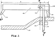
図1は本発明による可動連結されたケーシングの概略図であり、
図2は本発明による取付装置の第1の実施形態の断面図であり、
図3は本発明による取付装置の第2の実施形態の断面図であり、
図4は牽引部材を備えたケーシングの部分断面図であり、
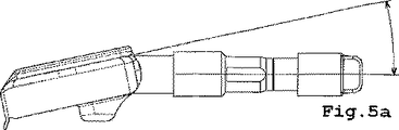
図5a及び図5bは牽引部材に対するケーシングの2つの可能な位置(それぞれ小さな傾斜角及び大きな傾斜角を有する)を示しており、
図6a及び図6bは、リムに取り付ける前のケーシング、牽引部材及びガスケットをそれぞれ別個に及び組み立てられた形で示す透視図であり、
図7は本発明による装置によりリム上に取り付けられたケーシングの透視図である。
20 牽引部材
30 牽引部材ロック手段
40 ケーシング
50 単方向傾斜ストッパ
60 通気孔
70 傾斜止め接触点
80 傾斜接触点
90,90’ 牽引部材と連動するケーシングの部分
100,100’ ケーシングと連動する牽引部材の部分
110 ガスケット
120 タイヤ
130 ケーシング取付部
Claims (9)
- 牽引部材(20)と、
前記牽引部材(20)に可動状に連結された、前記センサを収納するケーシング(40)と、
ひとたび前記ケーシング(40)が前記リム(10)と接触すると前記牽引部材を前記リム(10)上にロックする手段(30)とを有する、自動車のホイールリム(10)にセンサを取り付けるための装置において、
前記ケーシング(40)は、前記リム(10)の第1のゾーンに接触しながら連動する第1のストッパ(80)を有しており、該第1のストッパ(80)は、前記ケーシングの軸ピンを通る平面Pの一方の側に配置されており、第2のストッパ(70)は前記平面の他方の側に配置されており、前記牽引部材(20)による応力Fの下で前記リム(10)に押しつけられる、ことを特徴とする自動車のホイールリム(10)にセンサを取り付けるための装置。 - 前記第1のストッパと前記ケーシング(40)の軸ピンとの間の応力中心距離は、前記牽引部材(20)の並進を短くするため、前記ケーシング(40)の大きな角度変化が生じるように、前記第2のストッパと前記軸ピンとの間の応力中心距離に比べて短い、請求項1記載のセンサ取付装置。
- 前記ケーシング(40)は、ただ1つの方向に該ケーシングの傾斜を制限するための手段(50)を有している、請求項1又は2記載のセンサ取付装置。
- 前記牽引部材(20)は前記ケーシング(40)内に配置された軸(90)と連動するフック(100)を有する、請求項1から3のいずれか1項記載のセンサ取付装置。
- 前記牽引部材(20)は前記ケーシング(40)内に配置された相応する取付部と連動する軸を有する、請求項1から3のいずれか1項記載のセンサ取付装置。
- 前記牽引部材(20)は前記ケーシング(40)内に配置された相応する傾斜面(90’)と連動する突起部(100’)を有する、請求項1から3のいずれか1項記載のセンサ取付装置。
- 前記牽引部材(20)はタイヤ空気圧バルブ本体から構成されており、前記バルブ本体の足は前記ケーシング(40)と連動する、請求項1から6のいずれか1項記載のセンサ取付装置。
- 前記バルブをリム(10)上にロックする手段はナット(30)である、請求項7記載のセンサ取付装置。
- 牽引部材(20)と、
前記牽引部材(20)に可動状に連結された、前記センサを収納するケーシング(40)と、
ひとたび前記ケーシング(40)が前記リム(10)と接触すると前記牽引部材を前記リム(10)上にロックする手段(30)とを有する、自動車のホイールリム(10)にセンサを取り付けるため方法において、
前記牽引部材(20)による牽引力Fと、前記ケーシング(40)に組み込まれ且つ前記牽引部材(20)の軸を通る平面Pの一方の側に配置された第1のストッパ(80)の領域に作用する抗力とによって共同して発生させられた傾斜トルクの作用の下で、前記ケーシング(40)を前記リム(10)に向かって導き、
前記ストッパが前記リム(10)に接触すると、前記平面の他方の側に配置された、前記ケーシング(40)に組み込まれた第2のストッパ(70)が前記リム(10)と接触することにより、前記傾斜を停止させる、ことを特徴とする自動車のホイールリム(10)にセンサを取り付けるため方法。
Applications Claiming Priority (2)
| Application Number | Priority Date | Filing Date | Title |
|---|---|---|---|
| FR0111539A FR2829063B1 (fr) | 2001-09-06 | 2001-09-06 | Dispositif de montage d'un capteur sur une jante de roue de vehicule automobile et procede de montage associe |
| PCT/EP2002/008693 WO2003022603A1 (fr) | 2001-09-06 | 2002-08-05 | Dispositif de montage d'un capteur sur une jante de roue de vehicule automobile et procede de montage associe |
Publications (2)
| Publication Number | Publication Date |
|---|---|
| JP2005502515A JP2005502515A (ja) | 2005-01-27 |
| JP4021846B2 true JP4021846B2 (ja) | 2007-12-12 |
Family
ID=8867029
Family Applications (1)
| Application Number | Title | Priority Date | Filing Date |
|---|---|---|---|
| JP2003526705A Expired - Fee Related JP4021846B2 (ja) | 2001-09-06 | 2002-08-05 | 自動車のホイールリムにケーシングを取り付けるための装置及び関連する取り付け方法 |
Country Status (8)
| Country | Link |
|---|---|
| US (1) | US6865932B2 (ja) |
| EP (1) | EP1423285B1 (ja) |
| JP (1) | JP4021846B2 (ja) |
| KR (1) | KR20040028745A (ja) |
| DE (1) | DE60212410T2 (ja) |
| ES (1) | ES2262832T3 (ja) |
| FR (1) | FR2829063B1 (ja) |
| WO (1) | WO2003022603A1 (ja) |
Families Citing this family (14)
| Publication number | Priority date | Publication date | Assignee | Title |
|---|---|---|---|---|
| FR2838375B1 (fr) | 2002-04-16 | 2004-05-28 | Siemens Vdo Automotive | Dispositif d'articulation d'un capteur de pression de pneu sur une jante de vehicule automobile |
| US20040261512A1 (en) * | 2003-05-21 | 2004-12-30 | Daly Paul Desmond | Wheel with plastic rim and integral sensor |
| DE102005027002A1 (de) * | 2005-06-10 | 2006-12-21 | Lite-On Automotive Corp., Kaohsiung | Vorrichtung zum Abtasten des Reifenzustands und Verfahren zum Einbau derselben |
| US7021133B1 (en) | 2005-06-16 | 2006-04-04 | Lite-On Automotive Corp. | Tire condition sensing apparatus and mounting method thereof |
| KR100680793B1 (ko) * | 2005-11-21 | 2007-02-08 | 기아자동차주식회사 | 자동차의 휠 조립 장치 및 조립 방법 |
| JP4816095B2 (ja) * | 2006-01-20 | 2011-11-16 | 日産自動車株式会社 | タイヤ空気圧センサ取付構造およびタイヤホイール |
| US8803680B2 (en) * | 2006-06-21 | 2014-08-12 | Trw Automotive U.S. Llc | Tire pressure monitoring apparatus |
| WO2008055944A1 (en) * | 2006-11-09 | 2008-05-15 | Société de Technologie Michelin | Tyre valve fixing element |
| JP4853250B2 (ja) * | 2006-11-24 | 2012-01-11 | トヨタ自動車株式会社 | 車輪情報送信装置 |
| WO2008151267A1 (en) * | 2007-06-05 | 2008-12-11 | Continental Automotive Systems Us, Inc. | Formed flange for pressure monitoring valve stem mount |
| US8047068B2 (en) * | 2008-08-01 | 2011-11-01 | Schrader Electronics, Inc. | Snap-in tire valve |
| KR101666965B1 (ko) * | 2015-04-29 | 2016-10-17 | 씨트론 주식회사 | Tpms용 센서 부착장치 |
| EP3865319B1 (en) * | 2020-02-14 | 2023-04-05 | Continental Automotive Technologies GmbH | Valve system, tyre parameter monitoring system and method for mounting a tyre parameter monitoring system onto a wheel rim of a vehicle |
| CN113758729A (zh) * | 2020-12-31 | 2021-12-07 | 江苏瑞格信息科技有限公司 | 一种车辆监管设备及监管系统 |
Family Cites Families (17)
| Publication number | Priority date | Publication date | Assignee | Title |
|---|---|---|---|---|
| FR2616194B1 (fr) | 1987-06-04 | 1989-10-27 | France Etat Armement | Valve pneumatique pilotee perfectionnee pour la commande a distance du gonflage ou du degonflage d'une capacite |
| US4763517A (en) * | 1987-06-16 | 1988-08-16 | Feinberg Andrew S | Valve cap pressure indicator |
| EP0378891B1 (en) | 1988-01-11 | 1993-06-16 | Eaton Corporation | Rapid tire deflation |
| US5179981A (en) | 1988-05-25 | 1993-01-19 | Eaton Corporation | Fault detection method for central tire inflation system |
| CA1337080C (en) | 1988-05-25 | 1995-09-19 | Bradford Wallace Hicks | Fault detection method for central tire inflation system |
| US4924926A (en) | 1988-08-15 | 1990-05-15 | Eaton Corporation | Central tire inflation system |
| US4883105A (en) | 1988-09-12 | 1989-11-28 | Eaton Corporation | Wheel end valve for central tire inflation system |
| US4893664A (en) | 1988-09-12 | 1990-01-16 | Eaton Corporation | Wheel end valve for central tire inflation system |
| US4883106A (en) | 1989-01-19 | 1989-11-28 | Eaton Corporation | Rotary wheel-end assembly for tire inflation system |
| US5083457A (en) * | 1989-12-20 | 1992-01-28 | Tjs Development Corporation, Inc. | Remotely actuated tire pressure sensor |
| US5174839A (en) | 1991-07-05 | 1992-12-29 | Eaton Corporation | Drive axle sleeve and seal assembly |
| US5253687A (en) | 1991-09-03 | 1993-10-19 | Eaton Corporation | Vehicle central tire inflation system |
| US5180456A (en) | 1991-11-15 | 1993-01-19 | Eaton Corporation | Adaptive inflation control for vehicle central tire inflation system |
| US5844131A (en) * | 1995-06-26 | 1998-12-01 | Alligator Ventilfabrik Gmbh | Tire pressure sensor apparatus for a pneumatic tire of a vehicle |
| US5837891A (en) * | 1996-11-18 | 1998-11-17 | Bridge; David | Tire air pressure measuring device |
| US6055855A (en) | 1999-05-26 | 2000-05-02 | Trw Inc. | Tire pressure sensor wheel attachment apparatus |
| DE20015295U1 (de) * | 2000-08-11 | 2001-03-01 | Alligator Ventilfab Gmbh | Vorrichtung zum Messen des Reifendruckes in einem Luftreifen eines Fahrzeuges |
-
2001
- 2001-09-06 FR FR0111539A patent/FR2829063B1/fr not_active Expired - Fee Related
-
2002
- 2002-08-05 ES ES02762427T patent/ES2262832T3/es not_active Expired - Lifetime
- 2002-08-05 DE DE60212410T patent/DE60212410T2/de not_active Expired - Fee Related
- 2002-08-05 KR KR10-2003-7014116A patent/KR20040028745A/ko active IP Right Grant
- 2002-08-05 JP JP2003526705A patent/JP4021846B2/ja not_active Expired - Fee Related
- 2002-08-05 EP EP02762427A patent/EP1423285B1/fr not_active Expired - Lifetime
- 2002-08-05 US US10/473,864 patent/US6865932B2/en not_active Expired - Lifetime
- 2002-08-05 WO PCT/EP2002/008693 patent/WO2003022603A1/fr active IP Right Grant
Also Published As
| Publication number | Publication date |
|---|---|
| JP2005502515A (ja) | 2005-01-27 |
| WO2003022603A1 (fr) | 2003-03-20 |
| DE60212410T2 (de) | 2006-11-30 |
| KR20040028745A (ko) | 2004-04-03 |
| US20040103965A1 (en) | 2004-06-03 |
| ES2262832T3 (es) | 2006-12-01 |
| US6865932B2 (en) | 2005-03-15 |
| FR2829063B1 (fr) | 2003-10-31 |
| EP1423285B1 (fr) | 2006-06-14 |
| FR2829063A1 (fr) | 2003-03-07 |
| EP1423285A1 (fr) | 2004-06-02 |
| DE60212410D1 (de) | 2006-07-27 |
Similar Documents
| Publication | Publication Date | Title |
|---|---|---|
| JP4021846B2 (ja) | 自動車のホイールリムにケーシングを取り付けるための装置及び関連する取り付け方法 | |
| KR101137813B1 (ko) | 타이어 압력 모니터링 시스템 및 그의 타이어센서 | |
| US7516653B2 (en) | Tire pressure monitoring apparatus | |
| US4850263A (en) | Spring brake construction and method of manufacture thereof | |
| US4564056A (en) | Valve for wheels for tubeless bicycle tires | |
| US10549586B1 (en) | Electronic unit for measuring operating parameters of a vehicle wheel | |
| US11970029B2 (en) | Adapter, tyre parameter monitoring system and method for mounting a tyre parameter monitoring system onto a wheel rim | |
| US6367351B2 (en) | Steering wheel | |
| WO2017193548A1 (zh) | 爆胎应急支撑装置 | |
| US6070946A (en) | Dual wheel mounting system | |
| CN106103128B (zh) | 辐条轮辋 | |
| US11760138B2 (en) | Tire inflation valve equipped with adjusting system for a TPMS sensor | |
| KR101637258B1 (ko) | 차량의 드라이브 샤프트용 체결유닛 | |
| JP2008001222A (ja) | ホイール、エアーバルブ、並びに空気圧センサの移設方法 | |
| US6568765B1 (en) | Composite wheel having a shallow rim | |
| JP3973842B2 (ja) | チューブレスタイヤ用のワイヤースポークホイール | |
| US20130061994A1 (en) | Tire bead assist device wheel | |
| JPH09226331A (ja) | 楕円基部を有するバルブ | |
| JP4324659B2 (ja) | B型横装填ホイールのシール構造 | |
| KR200153444Y1 (ko) | 자동차용 스페어 타이어 고정구조 | |
| WO2015153001A1 (en) | Tire bead fitter for tire mounting machine | |
| JPS585952Y2 (ja) | タイヤクウキアツケンシユツキト エア−バルブノレンケツコウゾウ | |
| CN111479701A (zh) | 车轮保持系统 | |
| US726542A (en) | Wheel-tightener. | |
| JPS5828881Y2 (ja) | ホイ−ルにおけるエアセンサ−の取付構造 |
Legal Events
| Date | Code | Title | Description |
|---|---|---|---|
| A621 | Written request for application examination |
Free format text: JAPANESE INTERMEDIATE CODE: A621 Effective date: 20050518 |
|
| TRDD | Decision of grant or rejection written | ||
| A01 | Written decision to grant a patent or to grant a registration (utility model) |
Free format text: JAPANESE INTERMEDIATE CODE: A01 Effective date: 20070829 |
|
| A61 | First payment of annual fees (during grant procedure) |
Free format text: JAPANESE INTERMEDIATE CODE: A61 Effective date: 20070927 |
|
| FPAY | Renewal fee payment (event date is renewal date of database) |
Free format text: PAYMENT UNTIL: 20101005 Year of fee payment: 3 |
|
| R150 | Certificate of patent or registration of utility model |
Free format text: JAPANESE INTERMEDIATE CODE: R150 |
|
| FPAY | Renewal fee payment (event date is renewal date of database) |
Free format text: PAYMENT UNTIL: 20111005 Year of fee payment: 4 |
|
| FPAY | Renewal fee payment (event date is renewal date of database) |
Free format text: PAYMENT UNTIL: 20121005 Year of fee payment: 5 |
|
| FPAY | Renewal fee payment (event date is renewal date of database) |
Free format text: PAYMENT UNTIL: 20131005 Year of fee payment: 6 |
|
| R250 | Receipt of annual fees |
Free format text: JAPANESE INTERMEDIATE CODE: R250 |
|
| R250 | Receipt of annual fees |
Free format text: JAPANESE INTERMEDIATE CODE: R250 |
|
| R250 | Receipt of annual fees |
Free format text: JAPANESE INTERMEDIATE CODE: R250 |
|
| LAPS | Cancellation because of no payment of annual fees |