JP4021846B2 - Apparatus for attaching a casing to a wheel rim of an automobile and associated attachment method - Google Patents
Apparatus for attaching a casing to a wheel rim of an automobile and associated attachment method Download PDFInfo
- Publication number
- JP4021846B2 JP4021846B2 JP2003526705A JP2003526705A JP4021846B2 JP 4021846 B2 JP4021846 B2 JP 4021846B2 JP 2003526705 A JP2003526705 A JP 2003526705A JP 2003526705 A JP2003526705 A JP 2003526705A JP 4021846 B2 JP4021846 B2 JP 4021846B2
- Authority
- JP
- Japan
- Prior art keywords
- casing
- rim
- sensor
- traction member
- stopper
- Prior art date
- Legal status (The legal status is an assumption and is not a legal conclusion. Google has not performed a legal analysis and makes no representation as to the accuracy of the status listed.)
- Expired - Fee Related
Links
- 238000000034 method Methods 0.000 title claims description 6
- 230000009471 action Effects 0.000 claims description 4
- 230000008859 change Effects 0.000 claims description 2
- 238000013459 approach Methods 0.000 description 1
- 238000003754 machining Methods 0.000 description 1
- 230000004048 modification Effects 0.000 description 1
- 238000012986 modification Methods 0.000 description 1
- 230000002028 premature Effects 0.000 description 1
- 238000007789 sealing Methods 0.000 description 1
Images


Classifications
-
- B—PERFORMING OPERATIONS; TRANSPORTING
- B60—VEHICLES IN GENERAL
- B60C—VEHICLE TYRES; TYRE INFLATION; TYRE CHANGING; CONNECTING VALVES TO INFLATABLE ELASTIC BODIES IN GENERAL; DEVICES OR ARRANGEMENTS RELATED TO TYRES
- B60C23/00—Devices for measuring, signalling, controlling, or distributing tyre pressure or temperature, specially adapted for mounting on vehicles; Arrangement of tyre inflating devices on vehicles, e.g. of pumps or of tanks; Tyre cooling arrangements
- B60C23/02—Signalling devices actuated by tyre pressure
- B60C23/04—Signalling devices actuated by tyre pressure mounted on the wheel or tyre
- B60C23/0491—Constructional details of means for attaching the control device
- B60C23/0494—Valve stem attachments positioned inside the tyre chamber
-
- B—PERFORMING OPERATIONS; TRANSPORTING
- B60—VEHICLES IN GENERAL
- B60C—VEHICLE TYRES; TYRE INFLATION; TYRE CHANGING; CONNECTING VALVES TO INFLATABLE ELASTIC BODIES IN GENERAL; DEVICES OR ARRANGEMENTS RELATED TO TYRES
- B60C23/00—Devices for measuring, signalling, controlling, or distributing tyre pressure or temperature, specially adapted for mounting on vehicles; Arrangement of tyre inflating devices on vehicles, e.g. of pumps or of tanks; Tyre cooling arrangements
- B60C23/02—Signalling devices actuated by tyre pressure
- B60C23/04—Signalling devices actuated by tyre pressure mounted on the wheel or tyre
- B60C23/0408—Signalling devices actuated by tyre pressure mounted on the wheel or tyre transmitting the signals by non-mechanical means from the wheel or tyre to a vehicle body mounted receiver
Landscapes
- Engineering & Computer Science (AREA)
- Mechanical Engineering (AREA)
- Measuring Fluid Pressure (AREA)
Description
本発明は、自動車のホイールリムにケーシングを取り付けるための装置、より詳細には、タイヤ圧センサを取り付けるための装置と、関連する取り付け方法とに関する。 The present invention relates to an apparatus for mounting a casing on a wheel rim of an automobile, and more particularly to an apparatus for mounting a tire pressure sensor and an associated mounting method.
タイヤ圧センサを自動車のホイールリムに取り付けることは公知である。センサは一般にケーシングに組み込まれ、ケーシング自体はバルブに固定される。US6055855明細書では、例えば、センサのケーシング内に取付部を設け、そこにナットを差し込み、このナットで適合するねじ切りを有するバルブを締めることが提案されている。このアセンブリは次に第2のナットを介してリムに固定される。リム−センサ−バルブ−ナットのアセンブリの手動での位置決めは、上記ナットがリムに与えられた自由度の偏りによって動かないようにならない限り可能である。これにより、センサは異なるタイプのリムに対してある程度の適応性を得る。しかしながら、この従来技術は、多くの機械加工を含みまた多くの部材から成る特別なバルブを必要とするという重大な欠点を有している。同様に、2つのナットを同時に操作するため、センサの位置を迅速に調整することは非常に困難である。さらに、センサが実際にリムに接触することを保証するものはなく、接触が生じていないことに起因する振動によって、センサの時期尚早な摩耗及び潜在的な破損が生じる危険がある。 It is known to attach a tire pressure sensor to a wheel rim of an automobile. The sensor is generally built into the casing, which is itself fixed to the valve. In US 6055555, for example, it is proposed to provide a mounting part in the casing of the sensor, insert a nut therein, and tighten a valve having a threading that fits with this nut. This assembly is then secured to the rim via a second nut. Manual positioning of the rim-sensor-valve-nut assembly is possible as long as the nut does not move due to the degree of freedom imparted to the rim. This gives the sensor some flexibility for different types of rims. However, this prior art has the serious drawback of including a lot of machining and requiring special valves consisting of many parts. Similarly, since the two nuts are operated simultaneously, it is very difficult to quickly adjust the position of the sensor. Furthermore, there is no guarantee that the sensor will actually contact the rim, and there is a risk that premature wear and potential damage of the sensor will be caused by vibrations due to the absence of contact.
したがって、本発明が解決しようとする課題は、接触不良又はケーシングとリムとの間の過度に大きなオーバーハングによるセンサの破損の危険性がなく、様々なリムの輪郭にケーシングを自動的に押しつけることのできる迅速で、経済的で、使用し易く且つ信頼性の高い取り付け様式を提供することである。 Therefore, the problem to be solved by the present invention is to automatically press the casing against the contours of various rims without the risk of sensor failure due to poor contact or excessive overhang between the casing and the rim. It is to provide a quick, economical, easy to use and reliable mounting style.
そのために、本発明は自動車のホイールリムにセンサを取り付けるための装置に関係している。この装置は、
牽引部材と、
牽引部材に可動状に連結されたセンサ収納用ケーシングと、
ひとたびケーシングがリムと接触すると牽引部材をリム上にロックする手段とを有している。この装置の特徴は、前記ケーシングが、リムの第1のゾーンに接触しつつ連動する第1のストッパを有しており、該第1のストッパが、前記ケーシングの軸ピンを通る平面Pの一方の側に配置されており、第2のストッパが、前記平面の他方の側に配置されており、牽引部材による応力Fの下でリムに押しつけられることである。
To that end, the present invention relates to an apparatus for mounting a sensor on a wheel rim of an automobile. This device
A traction member;
A casing for housing the sensor movably connected to the pulling member;
Means for locking the traction member on the rim once the casing contacts the rim. This apparatus is characterized in that the casing has a first stopper that is interlocked while contacting the first zone of the rim, and the first stopper is one of the planes P passing through the shaft pin of the casing. The second stopper is disposed on the other side of the plane and is pressed against the rim under the stress F by the traction member.
有利には、第1のストッパとケーシングの軸ピンとの間の応力中心距離は、牽引部材の並進を短くするため、ケーシングの大きな角度変化が生じるように、第2のストッパと前記軸ピンとの間の応力中心距離に比べて短い。 Advantageously, the stress center distance between the first stopper and the axial pin of the casing shortens the translation of the traction member, so that a large angular change of the casing takes place between the second stopper and the axial pin. It is shorter than the stress center distance.
また、有利には、牽引部材はタイヤ空気圧バルブから構成されており、バルブの足はケーシングと連動し、バルブ本体はバルブをリム上にロックする機能を果たすナットを備えている。 Also advantageously, the traction member comprises a tire pneumatic valve, the foot of the valve interlocks with the casing, and the valve body includes a nut that functions to lock the valve onto the rim.
本発明はまた自動車のホイールリムにセンサを取り付けるための方法にも関している。この方法は、牽引部材による牽引力Fと第1のストッパの領域に作用する抗力とによって共同して発生させられた傾斜トルクの作用の下で、ケーシングをリムに向かって導き、前記ストッパがリムに接触すると、前記ケーシングに組み込まれた第2のストッパがリムと接触することにより傾斜を停止させることを特徴としている。ただし、第1のストッパはケーシングに組み込まれ、ケーシングの軸ピンを通る平面Pの一方の側に配置されており、ケーシングの上面に対して垂直であり、第2のストッパは、ケーシングに組み込まれており、前記平面の他方の側に配置されている。 The invention also relates to a method for mounting a sensor on an automobile wheel rim. In this method, the casing is guided toward the rim under the action of the inclination torque generated jointly by the traction force F by the traction member and the drag acting on the first stopper region, and the stopper is applied to the rim. When contact is made, the second stopper incorporated in the casing comes into contact with the rim to stop the inclination. However, the first stopper is incorporated in the casing and is disposed on one side of the plane P passing through the axial pin of the casing, and is perpendicular to the upper surface of the casing, and the second stopper is incorporated in the casing. And arranged on the other side of the plane.
本発明の他の特徴及び利点は以下の記述及び添付した図面から明らかとなる。添付した図面のうち、
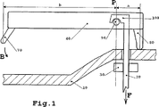
図1は本発明による可動連結されたケーシングの概略図であり、
図2は本発明による取付装置の第1の実施形態の断面図であり、
図3は本発明による取付装置の第2の実施形態の断面図であり、
図4は牽引部材を備えたケーシングの部分断面図であり、
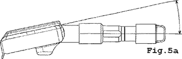
図5a及び図5bは牽引部材に対するケーシングの2つの可能な位置(それぞれ小さな傾斜角及び大きな傾斜角を有する)を示しており、
図6a及び図6bは、リムに取り付ける前のケーシング、牽引部材及びガスケットをそれぞれ別個に及び組み立てられた形で示す透視図であり、
図7は本発明による装置によりリム上に取り付けられたケーシングの透視図である。
Other features and advantages of the present invention will become apparent from the following description and accompanying drawings. Of the attached drawings,
FIG. 1 is a schematic view of a movable connected casing according to the present invention,
FIG. 2 is a cross-sectional view of a first embodiment of a mounting device according to the present invention,
FIG. 3 is a cross-sectional view of a second embodiment of the mounting device according to the present invention,
FIG. 4 is a partial sectional view of a casing provided with a pulling member,
Figures 5a and 5b show two possible positions of the casing relative to the traction member (with a small and a large inclination angle, respectively)
6a and 6b are perspective views showing the casing, the traction member and the gasket before being attached to the rim, separately and assembled,
FIG. 7 is a perspective view of a casing mounted on a rim by the apparatus according to the present invention.
本発明による装置は、3つの主要素、すなわち、牽引部材20、牽引部材20に可動状に連結されたセンサ収納用ケーシング40、牽引部材をロックする手段30から構成されている。図1を参照すると、この装置の動作様式がより良く理解される。牽引部材20はリム10の開口部に挿入され、ケーシング40がリム10に近づくように、牽引力Fがこの部材に加えられる。なお、リム10の開口部は、必ずではないが、有利にはバルブ孔である。したがって、ケーシング40に組み込まれた第1のストッパ80はリム10の第1のゾーンに接触し、牽引部材20によりケーシング40に及ぼされる牽引力Fとリム10により第1のストッパ80の領域に及ぼされる応力とにより発生する傾斜トルクの作用の下で、ケーシング40の傾斜(矢印B)が生じ、ケーシング40の第2のストッパ70がリム10に接触し、このようにしてケーシング40とリム10の間の緊密な接触が保証される。そのとき、ロック手段30が作動し、このようにしてロックされた牽引部材20はケーシングを確実にその位置に保持する。
The device according to the present invention comprises three main elements: a
距離《a》(第1のストッパに関する応力中心距離)は、ケーシング40が傾斜したときにケーシング40の角度位置の大きな変化が可能となるように、距離《b》(第2のストッパに関する応力中心距離)に比べて意図的に短く選択されていることに留意されたい。これは牽引部材20の行程を短くするためである。この行程は短いので、牽引部材20が大きく並進することはない。したがって、牽引部材20はリム10のサイズから外へ出ることはなく、したがって、自動車走行時に損傷する危険性がない。
The distance << a >> (stress center distance with respect to the first stopper) is such that the distance << b >> (stress center with respect to the second stopper) is such that the angular position of the
取り付けの図解は図2、4、6a、6b及び7に示されている。これらの図では、牽引部材20の機能はバルブにより果たされている。ケーシング40は取付部130を備えており、バルブはこの取付部に配置される。つぎにガスケット110が通され、このようにして構成されたアセンブリがリム10の内部に配置され、バルブは通常の位置をとる。そして、前記リム10がバルブナット30を一方の側とし、ケーシング40及びガスケット110を他方の側としてこれらの間に固定されるように、バルブ本体上でリム10の外からバルブナット30が締められる。ケーシング40は、バルブに牽引力Fを生じさせるバルブナット30のねじ締めの作用によって、第1のストッパ80の領域でリム10と接触するとすぐに、自動的に傾斜を生じる。この傾斜は、バルブナット30のねじ締めの続行に応じて、第2のストッパ70の領域でケーシング40をリム10に接触させる。こうして、ケーシングはリム10に対してしっかりと押しつけられる。バルブナット30の締めつけにより、この押しつけが完成し、ガスケット110の領域の封止が完全に保証される。バルブナット30のねじ締めはケーシング40の簡単かつ自動の押しつけを保証するに十分であると思われる。
An illustration of the mounting is shown in FIGS. 2, 4, 6a, 6b and 7. In these figures, the function of the
図2及び3は本発明に従った2つの実施形態であり、これらの実施形態では、牽引部材20は適合するバルブ足を備えた空気圧バルブ100,100’により構成されており、バルブのロック手段はナット30である。図2では、バルブ100の足は、ケーシング40に組み込まれた軸90と連動するフックの形をしており、一方図3では、バルブの足は突起100の形をしており、傾斜面90’に押しつけられる。これら2つの実施形態はケーシング40のリム10への傾斜を生じさせる。本発明の可能な変形(図示せず)は、バルブの足に、ケーシングに組み込まれた取付部に取り付けられる軸、又はケーシング40と牽引部材20との間の可動連結のための全く別の同機能の手段を備えさせることから成る。
FIGS. 2 and 3 show two embodiments according to the invention, in which the
ケーシング40は傾斜をガイドし、1方向のみを許すように構想されている。これにより、図示の例では、センサを衝撃から保護するため、ケーシング40をリム10の中でタイヤ120から最も遠い部分に押しつけることができ、また、タイヤ交換に関連した細工が可能となる。これはケーシング40及びバルブの連動する表面の形状そのものにより可能となるが、同様に、前記ケーシングに組み込まれたストッパ50によっても可能である。ただし、ストッパ50は1つの回転方向のみを許し、万が一の場合にはケーシングをロックする。
The
図5a及び5bは、本発明による装置により実現しうる傾斜の範囲を示している。このように、図示のケースでは、この傾斜範囲により、単純にバルブナット30を締めるだけで改造作業なしに同じアセンブリをリム10の異なる輪郭に合わせることが可能となる。図2及び3から気付かれるように、これらの様々な位置が、牽引部材20としてここで使用されているバルブの順調な動作を妨げることはまったくなく、ケーシング40が通気孔60をふさぐこともない。
Figures 5a and 5b show the range of tilting that can be achieved with the device according to the invention. Thus, in the illustrated case, this tilt range allows the same assembly to be matched to different contours of the
もちろん、本発明は単なる例として記載及び図示された上記実施形態に限定されない。したがって、本発明は、センサ以外の物体のための取り付け装置、又は空気圧バルブのバルブ孔以外への取り付けにも適用され、取り付け様式はリム10内に存在するすべての孔に合わせることが可能である。
Of course, the present invention is not limited to the embodiments described and illustrated by way of example only. Therefore, the present invention can be applied to an attachment device for an object other than a sensor or an attachment of a pneumatic valve other than a valve hole, and the attachment mode can be adapted to all holes existing in the
10 リム
20 牽引部材
30 牽引部材ロック手段
40 ケーシング
50 単方向傾斜ストッパ
60 通気孔
70 傾斜止め接触点
80 傾斜接触点
90,90’ 牽引部材と連動するケーシングの部分
100,100’ ケーシングと連動する牽引部材の部分
110 ガスケット
120 タイヤ
130 ケーシング取付部
DESCRIPTION OF
Claims (9)
前記牽引部材(20)に可動状に連結された、前記センサを収納するケーシング(40)と、
ひとたび前記ケーシング(40)が前記リム(10)と接触すると前記牽引部材を前記リム(10)上にロックする手段(30)とを有する、自動車のホイールリム(10)にセンサを取り付けるための装置において、
前記ケーシング(40)は、前記リム(10)の第1のゾーンに接触しながら連動する第1のストッパ(80)を有しており、該第1のストッパ(80)は、前記ケーシングの軸ピンを通る平面Pの一方の側に配置されており、第2のストッパ(70)は前記平面の他方の側に配置されており、前記牽引部材(20)による応力Fの下で前記リム(10)に押しつけられる、ことを特徴とする自動車のホイールリム(10)にセンサを取り付けるための装置。A traction member (20);
A casing (40) housing the sensor, movably connected to the traction member (20);
An apparatus for mounting a sensor on a wheel rim (10) of an automobile comprising means (30) for locking the traction member on the rim (10) once the casing (40) contacts the rim (10). In
The casing (40) has a first stopper (80) that interlocks while contacting the first zone of the rim (10), and the first stopper (80) is a shaft of the casing. The second stopper (70) is arranged on one side of the plane P passing through the pin, and the rim (under the stress F by the traction member (20) is arranged on the other side of the plane. 10) A device for mounting a sensor on a wheel rim (10) of a motor vehicle, characterized in that it is pressed against 10).
前記牽引部材(20)に可動状に連結された、前記センサを収納するケーシング(40)と、
ひとたび前記ケーシング(40)が前記リム(10)と接触すると前記牽引部材を前記リム(10)上にロックする手段(30)とを有する、自動車のホイールリム(10)にセンサを取り付けるため方法において、
前記牽引部材(20)による牽引力Fと、前記ケーシング(40)に組み込まれ且つ前記牽引部材(20)の軸を通る平面Pの一方の側に配置された第1のストッパ(80)の領域に作用する抗力とによって共同して発生させられた傾斜トルクの作用の下で、前記ケーシング(40)を前記リム(10)に向かって導き、
前記ストッパが前記リム(10)に接触すると、前記平面の他方の側に配置された、前記ケーシング(40)に組み込まれた第2のストッパ(70)が前記リム(10)と接触することにより、前記傾斜を停止させる、ことを特徴とする自動車のホイールリム(10)にセンサを取り付けるため方法。A traction member (20);
A casing (40) housing the sensor, movably connected to the traction member (20);
In a method for attaching a sensor to a wheel rim (10) of an automobile, comprising means (30) for locking the traction member on the rim (10) once the casing (40) contacts the rim (10). ,
In the region of the first stopper (80) arranged on one side of the plane P that is incorporated in the casing (40) and passes through the axis of the traction member (20), the traction force F by the traction member (20). Under the action of the tilting torque generated jointly by the acting drag, guiding the casing (40) towards the rim (10),
When the stopper comes into contact with the rim (10), a second stopper (70) arranged on the other side of the plane and built into the casing (40) comes into contact with the rim (10). A method for attaching a sensor to a wheel rim (10) of an automobile, characterized in that the tilting is stopped.
Applications Claiming Priority (2)
| Application Number | Priority Date | Filing Date | Title |
|---|---|---|---|
| FR0111539A FR2829063B1 (en) | 2001-09-06 | 2001-09-06 | DEVICE FOR MOUNTING A SENSOR ON A MOTOR VEHICLE WHEEL RIM AND ASSOCIATED MOUNTING METHOD |
| PCT/EP2002/008693 WO2003022603A1 (en) | 2001-09-06 | 2002-08-05 | Device for mounting a sensor on a motor vehicle wheel rim and related mounting method |
Publications (2)
| Publication Number | Publication Date |
|---|---|
| JP2005502515A JP2005502515A (en) | 2005-01-27 |
| JP4021846B2 true JP4021846B2 (en) | 2007-12-12 |
Family
ID=8867029
Family Applications (1)
| Application Number | Title | Priority Date | Filing Date |
|---|---|---|---|
| JP2003526705A Expired - Fee Related JP4021846B2 (en) | 2001-09-06 | 2002-08-05 | Apparatus for attaching a casing to a wheel rim of an automobile and associated attachment method |
Country Status (8)
| Country | Link |
|---|---|
| US (1) | US6865932B2 (en) |
| EP (1) | EP1423285B1 (en) |
| JP (1) | JP4021846B2 (en) |
| KR (1) | KR20040028745A (en) |
| DE (1) | DE60212410T2 (en) |
| ES (1) | ES2262832T3 (en) |
| FR (1) | FR2829063B1 (en) |
| WO (1) | WO2003022603A1 (en) |
Families Citing this family (14)
| Publication number | Priority date | Publication date | Assignee | Title |
|---|---|---|---|---|
| FR2838375B1 (en) | 2002-04-16 | 2004-05-28 | Siemens Vdo Automotive | DEVICE FOR ARTICULATING A TIRE PRESSURE SENSOR ON A MOTOR VEHICLE RIM |
| US20040261512A1 (en) * | 2003-05-21 | 2004-12-30 | Daly Paul Desmond | Wheel with plastic rim and integral sensor |
| DE102005027002A1 (en) * | 2005-06-10 | 2006-12-21 | Lite-On Automotive Corp., Kaohsiung | Tire condition sensing apparatus for vehicle, has valve assembly pivotally disposed in open end of ring plates, and comprising ring pad with one contact surface corresponding to another contact surface of plates |
| US7021133B1 (en) | 2005-06-16 | 2006-04-04 | Lite-On Automotive Corp. | Tire condition sensing apparatus and mounting method thereof |
| KR100680793B1 (en) * | 2005-11-21 | 2007-02-08 | 기아자동차주식회사 | Apparatus and method for assembling wheel of vehicle |
| JP4816095B2 (en) * | 2006-01-20 | 2011-11-16 | 日産自動車株式会社 | Tire pressure sensor mounting structure and tire wheel |
| US8803680B2 (en) * | 2006-06-21 | 2014-08-12 | Trw Automotive U.S. Llc | Tire pressure monitoring apparatus |
| US8776850B2 (en) * | 2006-11-09 | 2014-07-15 | Michelin Recherche Et Technique S.A. | Tire valve fixing element |
| JP4853250B2 (en) * | 2006-11-24 | 2012-01-11 | トヨタ自動車株式会社 | Wheel information transmitter |
| US20080302425A1 (en) * | 2007-06-05 | 2008-12-11 | Continental Automotive Systems Us, Inc. | Formed Flange For Pressure Monitoring Valve Stem Mount |
| US8047068B2 (en) * | 2008-08-01 | 2011-11-01 | Schrader Electronics, Inc. | Snap-in tire valve |
| KR101666965B1 (en) * | 2015-04-29 | 2016-10-17 | 씨트론 주식회사 | Fixing device for air pressure sensor of tire pressure monitoring system |
| EP3865319B1 (en) * | 2020-02-14 | 2023-04-05 | Continental Automotive Technologies GmbH | Valve system, tyre parameter monitoring system and method for mounting a tyre parameter monitoring system onto a wheel rim of a vehicle |
| CN113758729A (en) * | 2020-12-31 | 2021-12-07 | 江苏瑞格信息科技有限公司 | Vehicle supervision equipment and supervision system |
Family Cites Families (17)
| Publication number | Priority date | Publication date | Assignee | Title |
|---|---|---|---|---|
| FR2616194B1 (en) | 1987-06-04 | 1989-10-27 | France Etat Armement | IMPROVED PNEUMATIC PNEUMATIC VALVE FOR REMOTE CONTROL OF INFLATION OR DEFLATION OF A CAPACITY |
| US4763517A (en) * | 1987-06-16 | 1988-08-16 | Feinberg Andrew S | Valve cap pressure indicator |
| EP0378891B1 (en) | 1988-01-11 | 1993-06-16 | Eaton Corporation | Rapid tire deflation |
| US5179981A (en) | 1988-05-25 | 1993-01-19 | Eaton Corporation | Fault detection method for central tire inflation system |
| CA1337080C (en) | 1988-05-25 | 1995-09-19 | Bradford Wallace Hicks | Fault detection method for central tire inflation system |
| US4924926A (en) | 1988-08-15 | 1990-05-15 | Eaton Corporation | Central tire inflation system |
| US4883105A (en) | 1988-09-12 | 1989-11-28 | Eaton Corporation | Wheel end valve for central tire inflation system |
| US4893664A (en) | 1988-09-12 | 1990-01-16 | Eaton Corporation | Wheel end valve for central tire inflation system |
| US4883106A (en) | 1989-01-19 | 1989-11-28 | Eaton Corporation | Rotary wheel-end assembly for tire inflation system |
| US5083457A (en) * | 1989-12-20 | 1992-01-28 | Tjs Development Corporation, Inc. | Remotely actuated tire pressure sensor |
| US5174839A (en) | 1991-07-05 | 1992-12-29 | Eaton Corporation | Drive axle sleeve and seal assembly |
| US5253687A (en) | 1991-09-03 | 1993-10-19 | Eaton Corporation | Vehicle central tire inflation system |
| US5180456A (en) | 1991-11-15 | 1993-01-19 | Eaton Corporation | Adaptive inflation control for vehicle central tire inflation system |
| US5844131A (en) | 1995-06-26 | 1998-12-01 | Alligator Ventilfabrik Gmbh | Tire pressure sensor apparatus for a pneumatic tire of a vehicle |
| US5837891A (en) * | 1996-11-18 | 1998-11-17 | Bridge; David | Tire air pressure measuring device |
| US6055855A (en) | 1999-05-26 | 2000-05-02 | Trw Inc. | Tire pressure sensor wheel attachment apparatus |
| DE20015295U1 (en) * | 2000-08-11 | 2001-03-01 | Alligator Ventilfab Gmbh | Device for measuring the tire pressure in a pneumatic tire of a vehicle |
-
2001
- 2001-09-06 FR FR0111539A patent/FR2829063B1/en not_active Expired - Fee Related
-
2002
- 2002-08-05 DE DE60212410T patent/DE60212410T2/en not_active Expired - Fee Related
- 2002-08-05 ES ES02762427T patent/ES2262832T3/en not_active Expired - Lifetime
- 2002-08-05 WO PCT/EP2002/008693 patent/WO2003022603A1/en active IP Right Grant
- 2002-08-05 EP EP02762427A patent/EP1423285B1/en not_active Expired - Lifetime
- 2002-08-05 US US10/473,864 patent/US6865932B2/en not_active Expired - Lifetime
- 2002-08-05 KR KR10-2003-7014116A patent/KR20040028745A/en active IP Right Grant
- 2002-08-05 JP JP2003526705A patent/JP4021846B2/en not_active Expired - Fee Related
Also Published As
| Publication number | Publication date |
|---|---|
| KR20040028745A (en) | 2004-04-03 |
| DE60212410T2 (en) | 2006-11-30 |
| EP1423285A1 (en) | 2004-06-02 |
| FR2829063B1 (en) | 2003-10-31 |
| ES2262832T3 (en) | 2006-12-01 |
| WO2003022603A1 (en) | 2003-03-20 |
| DE60212410D1 (en) | 2006-07-27 |
| US6865932B2 (en) | 2005-03-15 |
| US20040103965A1 (en) | 2004-06-03 |
| JP2005502515A (en) | 2005-01-27 |
| EP1423285B1 (en) | 2006-06-14 |
| FR2829063A1 (en) | 2003-03-07 |
Similar Documents
| Publication | Publication Date | Title |
|---|---|---|
| JP4021846B2 (en) | Apparatus for attaching a casing to a wheel rim of an automobile and associated attachment method | |
| US7516653B2 (en) | Tire pressure monitoring apparatus | |
| US4850263A (en) | Spring brake construction and method of manufacture thereof | |
| US20120017672A1 (en) | Tire pressure monitoring system and tire pressure sensor thereof | |
| US4564056A (en) | Valve for wheels for tubeless bicycle tires | |
| US10549586B1 (en) | Electronic unit for measuring operating parameters of a vehicle wheel | |
| US11970029B2 (en) | Adapter, tyre parameter monitoring system and method for mounting a tyre parameter monitoring system onto a wheel rim | |
| WO2017193548A1 (en) | Emergency supporting device for tire blowout | |
| US6367351B2 (en) | Steering wheel | |
| US6070946A (en) | Dual wheel mounting system | |
| KR101637258B1 (en) | Mounting unit for drive shaft of vehicle | |
| JP2008001222A (en) | Wheel, air valve and transfer method of pneumatic sensor | |
| EP1340630A1 (en) | Connection system between valve and sensor for vehicle tyres | |
| JP3973842B2 (en) | Wire spoke wheels for tubeless tires | |
| US20130061994A1 (en) | Tire bead assist device wheel | |
| GB2580387A (en) | Adapter, tyre parameter monitoring system and method for mounting a tyre parameter monitoring system onto a wheel rim | |
| JP2005534548A (en) | Composite wheel with shallow rim | |
| JPH09226331A (en) | Valve having elliptical base | |
| JP4324659B2 (en) | Seal structure of B type lateral loading wheel | |
| KR200153444Y1 (en) | Spare tire fixing structure | |
| WO2015153001A1 (en) | Tire bead fitter for tire mounting machine | |
| JPS585952Y2 (en) | Tire clearance and air valve clearance | |
| CN111479701A (en) | Wheel retention system | |
| KR20060004180A (en) | Structure for coupling steering column and wheel in a car | |
| US726542A (en) | Wheel-tightener. |
Legal Events
| Date | Code | Title | Description |
|---|---|---|---|
| A621 | Written request for application examination |
Free format text: JAPANESE INTERMEDIATE CODE: A621 Effective date: 20050518 |
|
| TRDD | Decision of grant or rejection written | ||
| A01 | Written decision to grant a patent or to grant a registration (utility model) |
Free format text: JAPANESE INTERMEDIATE CODE: A01 Effective date: 20070829 |
|
| A61 | First payment of annual fees (during grant procedure) |
Free format text: JAPANESE INTERMEDIATE CODE: A61 Effective date: 20070927 |
|
| FPAY | Renewal fee payment (event date is renewal date of database) |
Free format text: PAYMENT UNTIL: 20101005 Year of fee payment: 3 |
|
| R150 | Certificate of patent or registration of utility model |
Free format text: JAPANESE INTERMEDIATE CODE: R150 |
|
| FPAY | Renewal fee payment (event date is renewal date of database) |
Free format text: PAYMENT UNTIL: 20111005 Year of fee payment: 4 |
|
| FPAY | Renewal fee payment (event date is renewal date of database) |
Free format text: PAYMENT UNTIL: 20121005 Year of fee payment: 5 |
|
| FPAY | Renewal fee payment (event date is renewal date of database) |
Free format text: PAYMENT UNTIL: 20131005 Year of fee payment: 6 |
|
| R250 | Receipt of annual fees |
Free format text: JAPANESE INTERMEDIATE CODE: R250 |
|
| R250 | Receipt of annual fees |
Free format text: JAPANESE INTERMEDIATE CODE: R250 |
|
| R250 | Receipt of annual fees |
Free format text: JAPANESE INTERMEDIATE CODE: R250 |
|
| LAPS | Cancellation because of no payment of annual fees |