JP2017143096A - 配線基板、半導体装置及び配線基板の製造方法 - Google Patents
配線基板、半導体装置及び配線基板の製造方法 Download PDFInfo
- Publication number
- JP2017143096A JP2017143096A JP2016021698A JP2016021698A JP2017143096A JP 2017143096 A JP2017143096 A JP 2017143096A JP 2016021698 A JP2016021698 A JP 2016021698A JP 2016021698 A JP2016021698 A JP 2016021698A JP 2017143096 A JP2017143096 A JP 2017143096A
- Authority
- JP
- Japan
- Prior art keywords
- opening
- hole
- holes
- core substrate
- wiring board
- Prior art date
- Legal status (The legal status is an assumption and is not a legal conclusion. Google has not performed a legal analysis and makes no representation as to the accuracy of the status listed.)
- Granted
Links
Images


Classifications
-
- H—ELECTRICITY
- H01—ELECTRIC ELEMENTS
- H01L—SEMICONDUCTOR DEVICES NOT COVERED BY CLASS H10
- H01L25/00—Assemblies consisting of a plurality of individual semiconductor or other solid state devices ; Multistep manufacturing processes thereof
- H01L25/03—Assemblies consisting of a plurality of individual semiconductor or other solid state devices ; Multistep manufacturing processes thereof all the devices being of a type provided for in the same subgroup of groups H01L27/00 - H01L33/00, or in a single subclass of H10K, H10N, e.g. assemblies of rectifier diodes
- H01L25/10—Assemblies consisting of a plurality of individual semiconductor or other solid state devices ; Multistep manufacturing processes thereof all the devices being of a type provided for in the same subgroup of groups H01L27/00 - H01L33/00, or in a single subclass of H10K, H10N, e.g. assemblies of rectifier diodes the devices having separate containers
- H01L25/11—Assemblies consisting of a plurality of individual semiconductor or other solid state devices ; Multistep manufacturing processes thereof all the devices being of a type provided for in the same subgroup of groups H01L27/00 - H01L33/00, or in a single subclass of H10K, H10N, e.g. assemblies of rectifier diodes the devices having separate containers the devices being of a type provided for in group H01L29/00
- H01L25/117—Stacked arrangements of devices
-
- H—ELECTRICITY
- H01—ELECTRIC ELEMENTS
- H01L—SEMICONDUCTOR DEVICES NOT COVERED BY CLASS H10
- H01L21/00—Processes or apparatus adapted for the manufacture or treatment of semiconductor or solid state devices or of parts thereof
- H01L21/02—Manufacture or treatment of semiconductor devices or of parts thereof
- H01L21/04—Manufacture or treatment of semiconductor devices or of parts thereof the devices having at least one potential-jump barrier or surface barrier, e.g. PN junction, depletion layer or carrier concentration layer
- H01L21/50—Assembly of semiconductor devices using processes or apparatus not provided for in a single one of the subgroups H01L21/06 - H01L21/326, e.g. sealing of a cap to a base of a container
- H01L21/56—Encapsulations, e.g. encapsulation layers, coatings
- H01L21/563—Encapsulation of active face of flip-chip device, e.g. underfilling or underencapsulation of flip-chip, encapsulation preform on chip or mounting substrate
-
- H—ELECTRICITY
- H01—ELECTRIC ELEMENTS
- H01L—SEMICONDUCTOR DEVICES NOT COVERED BY CLASS H10
- H01L23/00—Details of semiconductor or other solid state devices
- H01L23/28—Encapsulations, e.g. encapsulating layers, coatings, e.g. for protection
- H01L23/31—Encapsulations, e.g. encapsulating layers, coatings, e.g. for protection characterised by the arrangement or shape
- H01L23/3107—Encapsulations, e.g. encapsulating layers, coatings, e.g. for protection characterised by the arrangement or shape the device being completely enclosed
- H01L23/3121—Encapsulations, e.g. encapsulating layers, coatings, e.g. for protection characterised by the arrangement or shape the device being completely enclosed a substrate forming part of the encapsulation
- H01L23/3128—Encapsulations, e.g. encapsulating layers, coatings, e.g. for protection characterised by the arrangement or shape the device being completely enclosed a substrate forming part of the encapsulation the substrate having spherical bumps for external connection
-
- H—ELECTRICITY
- H01—ELECTRIC ELEMENTS
- H01L—SEMICONDUCTOR DEVICES NOT COVERED BY CLASS H10
- H01L23/00—Details of semiconductor or other solid state devices
- H01L23/48—Arrangements for conducting electric current to or from the solid state body in operation, e.g. leads, terminal arrangements ; Selection of materials therefor
- H01L23/488—Arrangements for conducting electric current to or from the solid state body in operation, e.g. leads, terminal arrangements ; Selection of materials therefor consisting of soldered or bonded constructions
- H01L23/498—Leads, i.e. metallisations or lead-frames on insulating substrates, e.g. chip carriers
- H01L23/49822—Multilayer substrates
-
- H—ELECTRICITY
- H01—ELECTRIC ELEMENTS
- H01L—SEMICONDUCTOR DEVICES NOT COVERED BY CLASS H10
- H01L23/00—Details of semiconductor or other solid state devices
- H01L23/48—Arrangements for conducting electric current to or from the solid state body in operation, e.g. leads, terminal arrangements ; Selection of materials therefor
- H01L23/488—Arrangements for conducting electric current to or from the solid state body in operation, e.g. leads, terminal arrangements ; Selection of materials therefor consisting of soldered or bonded constructions
- H01L23/498—Leads, i.e. metallisations or lead-frames on insulating substrates, e.g. chip carriers
- H01L23/49827—Via connections through the substrates, e.g. pins going through the substrate, coaxial cables
-
- H—ELECTRICITY
- H01—ELECTRIC ELEMENTS
- H01L—SEMICONDUCTOR DEVICES NOT COVERED BY CLASS H10
- H01L23/00—Details of semiconductor or other solid state devices
- H01L23/52—Arrangements for conducting electric current within the device in operation from one component to another, i.e. interconnections, e.g. wires, lead frames
- H01L23/538—Arrangements for conducting electric current within the device in operation from one component to another, i.e. interconnections, e.g. wires, lead frames the interconnection structure between a plurality of semiconductor chips being formed on, or in, insulating substrates
- H01L23/5389—Arrangements for conducting electric current within the device in operation from one component to another, i.e. interconnections, e.g. wires, lead frames the interconnection structure between a plurality of semiconductor chips being formed on, or in, insulating substrates the chips being integrally enclosed by the interconnect and support structures
-
- H—ELECTRICITY
- H01—ELECTRIC ELEMENTS
- H01L—SEMICONDUCTOR DEVICES NOT COVERED BY CLASS H10
- H01L24/00—Arrangements for connecting or disconnecting semiconductor or solid-state bodies; Methods or apparatus related thereto
- H01L24/01—Means for bonding being attached to, or being formed on, the surface to be connected, e.g. chip-to-package, die-attach, "first-level" interconnects; Manufacturing methods related thereto
- H01L24/02—Bonding areas ; Manufacturing methods related thereto
- H01L24/07—Structure, shape, material or disposition of the bonding areas after the connecting process
- H01L24/09—Structure, shape, material or disposition of the bonding areas after the connecting process of a plurality of bonding areas
-
- H—ELECTRICITY
- H01—ELECTRIC ELEMENTS
- H01L—SEMICONDUCTOR DEVICES NOT COVERED BY CLASS H10
- H01L24/00—Arrangements for connecting or disconnecting semiconductor or solid-state bodies; Methods or apparatus related thereto
- H01L24/01—Means for bonding being attached to, or being formed on, the surface to be connected, e.g. chip-to-package, die-attach, "first-level" interconnects; Manufacturing methods related thereto
- H01L24/10—Bump connectors ; Manufacturing methods related thereto
- H01L24/15—Structure, shape, material or disposition of the bump connectors after the connecting process
- H01L24/17—Structure, shape, material or disposition of the bump connectors after the connecting process of a plurality of bump connectors
-
- H—ELECTRICITY
- H01—ELECTRIC ELEMENTS
- H01L—SEMICONDUCTOR DEVICES NOT COVERED BY CLASS H10
- H01L24/00—Arrangements for connecting or disconnecting semiconductor or solid-state bodies; Methods or apparatus related thereto
- H01L24/01—Means for bonding being attached to, or being formed on, the surface to be connected, e.g. chip-to-package, die-attach, "first-level" interconnects; Manufacturing methods related thereto
- H01L24/18—High density interconnect [HDI] connectors; Manufacturing methods related thereto
- H01L24/19—Manufacturing methods of high density interconnect preforms
-
- H—ELECTRICITY
- H01—ELECTRIC ELEMENTS
- H01L—SEMICONDUCTOR DEVICES NOT COVERED BY CLASS H10
- H01L24/00—Arrangements for connecting or disconnecting semiconductor or solid-state bodies; Methods or apparatus related thereto
- H01L24/01—Means for bonding being attached to, or being formed on, the surface to be connected, e.g. chip-to-package, die-attach, "first-level" interconnects; Manufacturing methods related thereto
- H01L24/18—High density interconnect [HDI] connectors; Manufacturing methods related thereto
- H01L24/20—Structure, shape, material or disposition of high density interconnect preforms
-
- H—ELECTRICITY
- H01—ELECTRIC ELEMENTS
- H01L—SEMICONDUCTOR DEVICES NOT COVERED BY CLASS H10
- H01L24/00—Arrangements for connecting or disconnecting semiconductor or solid-state bodies; Methods or apparatus related thereto
- H01L24/01—Means for bonding being attached to, or being formed on, the surface to be connected, e.g. chip-to-package, die-attach, "first-level" interconnects; Manufacturing methods related thereto
- H01L24/18—High density interconnect [HDI] connectors; Manufacturing methods related thereto
- H01L24/23—Structure, shape, material or disposition of the high density interconnect connectors after the connecting process
- H01L24/25—Structure, shape, material or disposition of the high density interconnect connectors after the connecting process of a plurality of high density interconnect connectors
-
- H—ELECTRICITY
- H01—ELECTRIC ELEMENTS
- H01L—SEMICONDUCTOR DEVICES NOT COVERED BY CLASS H10
- H01L24/00—Arrangements for connecting or disconnecting semiconductor or solid-state bodies; Methods or apparatus related thereto
- H01L24/93—Batch processes
- H01L24/95—Batch processes at chip-level, i.e. with connecting carried out on a plurality of singulated devices, i.e. on diced chips
- H01L24/96—Batch processes at chip-level, i.e. with connecting carried out on a plurality of singulated devices, i.e. on diced chips the devices being encapsulated in a common layer, e.g. neo-wafer or pseudo-wafer, said common layer being separable into individual assemblies after connecting
-
- H—ELECTRICITY
- H01—ELECTRIC ELEMENTS
- H01L—SEMICONDUCTOR DEVICES NOT COVERED BY CLASS H10
- H01L21/00—Processes or apparatus adapted for the manufacture or treatment of semiconductor or solid state devices or of parts thereof
- H01L21/02—Manufacture or treatment of semiconductor devices or of parts thereof
- H01L21/04—Manufacture or treatment of semiconductor devices or of parts thereof the devices having at least one potential-jump barrier or surface barrier, e.g. PN junction, depletion layer or carrier concentration layer
- H01L21/50—Assembly of semiconductor devices using processes or apparatus not provided for in a single one of the subgroups H01L21/06 - H01L21/326, e.g. sealing of a cap to a base of a container
- H01L21/56—Encapsulations, e.g. encapsulation layers, coatings
- H01L21/568—Temporary substrate used as encapsulation process aid
-
- H—ELECTRICITY
- H01—ELECTRIC ELEMENTS
- H01L—SEMICONDUCTOR DEVICES NOT COVERED BY CLASS H10
- H01L2224/00—Indexing scheme for arrangements for connecting or disconnecting semiconductor or solid-state bodies and methods related thereto as covered by H01L24/00
- H01L2224/01—Means for bonding being attached to, or being formed on, the surface to be connected, e.g. chip-to-package, die-attach, "first-level" interconnects; Manufacturing methods related thereto
- H01L2224/02—Bonding areas; Manufacturing methods related thereto
- H01L2224/04—Structure, shape, material or disposition of the bonding areas prior to the connecting process
- H01L2224/0401—Bonding areas specifically adapted for bump connectors, e.g. under bump metallisation [UBM]
-
- H—ELECTRICITY
- H01—ELECTRIC ELEMENTS
- H01L—SEMICONDUCTOR DEVICES NOT COVERED BY CLASS H10
- H01L2224/00—Indexing scheme for arrangements for connecting or disconnecting semiconductor or solid-state bodies and methods related thereto as covered by H01L24/00
- H01L2224/01—Means for bonding being attached to, or being formed on, the surface to be connected, e.g. chip-to-package, die-attach, "first-level" interconnects; Manufacturing methods related thereto
- H01L2224/02—Bonding areas; Manufacturing methods related thereto
- H01L2224/04—Structure, shape, material or disposition of the bonding areas prior to the connecting process
- H01L2224/04105—Bonding areas formed on an encapsulation of the semiconductor or solid-state body, e.g. bonding areas on chip-scale packages
-
- H—ELECTRICITY
- H01—ELECTRIC ELEMENTS
- H01L—SEMICONDUCTOR DEVICES NOT COVERED BY CLASS H10
- H01L2224/00—Indexing scheme for arrangements for connecting or disconnecting semiconductor or solid-state bodies and methods related thereto as covered by H01L24/00
- H01L2224/01—Means for bonding being attached to, or being formed on, the surface to be connected, e.g. chip-to-package, die-attach, "first-level" interconnects; Manufacturing methods related thereto
- H01L2224/10—Bump connectors; Manufacturing methods related thereto
- H01L2224/12—Structure, shape, material or disposition of the bump connectors prior to the connecting process
- H01L2224/12105—Bump connectors formed on an encapsulation of the semiconductor or solid-state body, e.g. bumps on chip-scale packages
-
- H—ELECTRICITY
- H01—ELECTRIC ELEMENTS
- H01L—SEMICONDUCTOR DEVICES NOT COVERED BY CLASS H10
- H01L2224/00—Indexing scheme for arrangements for connecting or disconnecting semiconductor or solid-state bodies and methods related thereto as covered by H01L24/00
- H01L2224/01—Means for bonding being attached to, or being formed on, the surface to be connected, e.g. chip-to-package, die-attach, "first-level" interconnects; Manufacturing methods related thereto
- H01L2224/10—Bump connectors; Manufacturing methods related thereto
- H01L2224/15—Structure, shape, material or disposition of the bump connectors after the connecting process
- H01L2224/16—Structure, shape, material or disposition of the bump connectors after the connecting process of an individual bump connector
- H01L2224/161—Disposition
- H01L2224/16151—Disposition the bump connector connecting between a semiconductor or solid-state body and an item not being a semiconductor or solid-state body, e.g. chip-to-substrate, chip-to-passive
- H01L2224/16221—Disposition the bump connector connecting between a semiconductor or solid-state body and an item not being a semiconductor or solid-state body, e.g. chip-to-substrate, chip-to-passive the body and the item being stacked
- H01L2224/16225—Disposition the bump connector connecting between a semiconductor or solid-state body and an item not being a semiconductor or solid-state body, e.g. chip-to-substrate, chip-to-passive the body and the item being stacked the item being non-metallic, e.g. insulating substrate with or without metallisation
- H01L2224/16227—Disposition the bump connector connecting between a semiconductor or solid-state body and an item not being a semiconductor or solid-state body, e.g. chip-to-substrate, chip-to-passive the body and the item being stacked the item being non-metallic, e.g. insulating substrate with or without metallisation the bump connector connecting to a bond pad of the item
-
- H—ELECTRICITY
- H01—ELECTRIC ELEMENTS
- H01L—SEMICONDUCTOR DEVICES NOT COVERED BY CLASS H10
- H01L2224/00—Indexing scheme for arrangements for connecting or disconnecting semiconductor or solid-state bodies and methods related thereto as covered by H01L24/00
- H01L2224/01—Means for bonding being attached to, or being formed on, the surface to be connected, e.g. chip-to-package, die-attach, "first-level" interconnects; Manufacturing methods related thereto
- H01L2224/18—High density interconnect [HDI] connectors; Manufacturing methods related thereto
- H01L2224/23—Structure, shape, material or disposition of the high density interconnect connectors after the connecting process
- H01L2224/25—Structure, shape, material or disposition of the high density interconnect connectors after the connecting process of a plurality of high density interconnect connectors
- H01L2224/251—Disposition
- H01L2224/2518—Disposition being disposed on at least two different sides of the body, e.g. dual array
-
- H—ELECTRICITY
- H01—ELECTRIC ELEMENTS
- H01L—SEMICONDUCTOR DEVICES NOT COVERED BY CLASS H10
- H01L2224/00—Indexing scheme for arrangements for connecting or disconnecting semiconductor or solid-state bodies and methods related thereto as covered by H01L24/00
- H01L2224/01—Means for bonding being attached to, or being formed on, the surface to be connected, e.g. chip-to-package, die-attach, "first-level" interconnects; Manufacturing methods related thereto
- H01L2224/26—Layer connectors, e.g. plate connectors, solder or adhesive layers; Manufacturing methods related thereto
- H01L2224/31—Structure, shape, material or disposition of the layer connectors after the connecting process
- H01L2224/32—Structure, shape, material or disposition of the layer connectors after the connecting process of an individual layer connector
- H01L2224/321—Disposition
- H01L2224/32151—Disposition the layer connector connecting between a semiconductor or solid-state body and an item not being a semiconductor or solid-state body, e.g. chip-to-substrate, chip-to-passive
- H01L2224/32221—Disposition the layer connector connecting between a semiconductor or solid-state body and an item not being a semiconductor or solid-state body, e.g. chip-to-substrate, chip-to-passive the body and the item being stacked
- H01L2224/32225—Disposition the layer connector connecting between a semiconductor or solid-state body and an item not being a semiconductor or solid-state body, e.g. chip-to-substrate, chip-to-passive the body and the item being stacked the item being non-metallic, e.g. insulating substrate with or without metallisation
-
- H—ELECTRICITY
- H01—ELECTRIC ELEMENTS
- H01L—SEMICONDUCTOR DEVICES NOT COVERED BY CLASS H10
- H01L2224/00—Indexing scheme for arrangements for connecting or disconnecting semiconductor or solid-state bodies and methods related thereto as covered by H01L24/00
- H01L2224/73—Means for bonding being of different types provided for in two or more of groups H01L2224/10, H01L2224/18, H01L2224/26, H01L2224/34, H01L2224/42, H01L2224/50, H01L2224/63, H01L2224/71
- H01L2224/732—Location after the connecting process
- H01L2224/73201—Location after the connecting process on the same surface
- H01L2224/73203—Bump and layer connectors
- H01L2224/73204—Bump and layer connectors the bump connector being embedded into the layer connector
-
- H—ELECTRICITY
- H01—ELECTRIC ELEMENTS
- H01L—SEMICONDUCTOR DEVICES NOT COVERED BY CLASS H10
- H01L2224/00—Indexing scheme for arrangements for connecting or disconnecting semiconductor or solid-state bodies and methods related thereto as covered by H01L24/00
- H01L2224/91—Methods for connecting semiconductor or solid state bodies including different methods provided for in two or more of groups H01L2224/80 - H01L2224/90
- H01L2224/92—Specific sequence of method steps
- H01L2224/921—Connecting a surface with connectors of different types
- H01L2224/9212—Sequential connecting processes
- H01L2224/92122—Sequential connecting processes the first connecting process involving a bump connector
- H01L2224/92125—Sequential connecting processes the first connecting process involving a bump connector the second connecting process involving a layer connector
-
- H—ELECTRICITY
- H01—ELECTRIC ELEMENTS
- H01L—SEMICONDUCTOR DEVICES NOT COVERED BY CLASS H10
- H01L2225/00—Details relating to assemblies covered by the group H01L25/00 but not provided for in its subgroups
- H01L2225/03—All the devices being of a type provided for in the same subgroup of groups H01L27/00 - H01L33/648 and H10K99/00
- H01L2225/10—All the devices being of a type provided for in the same subgroup of groups H01L27/00 - H01L33/648 and H10K99/00 the devices having separate containers
- H01L2225/1005—All the devices being of a type provided for in the same subgroup of groups H01L27/00 - H01L33/648 and H10K99/00 the devices having separate containers the devices being of a type provided for in group H01L27/00
- H01L2225/1011—All the devices being of a type provided for in the same subgroup of groups H01L27/00 - H01L33/648 and H10K99/00 the devices having separate containers the devices being of a type provided for in group H01L27/00 the containers being in a stacked arrangement
- H01L2225/1017—All the devices being of a type provided for in the same subgroup of groups H01L27/00 - H01L33/648 and H10K99/00 the devices having separate containers the devices being of a type provided for in group H01L27/00 the containers being in a stacked arrangement the lowermost container comprising a device support
- H01L2225/1035—All the devices being of a type provided for in the same subgroup of groups H01L27/00 - H01L33/648 and H10K99/00 the devices having separate containers the devices being of a type provided for in group H01L27/00 the containers being in a stacked arrangement the lowermost container comprising a device support the device being entirely enclosed by the support, e.g. high-density interconnect [HDI]
-
- H—ELECTRICITY
- H01—ELECTRIC ELEMENTS
- H01L—SEMICONDUCTOR DEVICES NOT COVERED BY CLASS H10
- H01L23/00—Details of semiconductor or other solid state devices
- H01L23/12—Mountings, e.g. non-detachable insulating substrates
- H01L23/13—Mountings, e.g. non-detachable insulating substrates characterised by the shape
-
- H—ELECTRICITY
- H01—ELECTRIC ELEMENTS
- H01L—SEMICONDUCTOR DEVICES NOT COVERED BY CLASS H10
- H01L23/00—Details of semiconductor or other solid state devices
- H01L23/48—Arrangements for conducting electric current to or from the solid state body in operation, e.g. leads, terminal arrangements ; Selection of materials therefor
- H01L23/488—Arrangements for conducting electric current to or from the solid state body in operation, e.g. leads, terminal arrangements ; Selection of materials therefor consisting of soldered or bonded constructions
- H01L23/498—Leads, i.e. metallisations or lead-frames on insulating substrates, e.g. chip carriers
- H01L23/49811—Additional leads joined to the metallisation on the insulating substrate, e.g. pins, bumps, wires, flat leads
- H01L23/49816—Spherical bumps on the substrate for external connection, e.g. ball grid arrays [BGA]
-
- H—ELECTRICITY
- H01—ELECTRIC ELEMENTS
- H01L—SEMICONDUCTOR DEVICES NOT COVERED BY CLASS H10
- H01L2924/00—Indexing scheme for arrangements or methods for connecting or disconnecting semiconductor or solid-state bodies as covered by H01L24/00
- H01L2924/15—Details of package parts other than the semiconductor or other solid state devices to be connected
- H01L2924/151—Die mounting substrate
- H01L2924/153—Connection portion
- H01L2924/1531—Connection portion the connection portion being formed only on the surface of the substrate opposite to the die mounting surface
- H01L2924/15311—Connection portion the connection portion being formed only on the surface of the substrate opposite to the die mounting surface being a ball array, e.g. BGA
Abstract
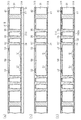
【解決手段】配線基板20は、コア基板31と、コア基板31の第1面31Aと第2面31Bとの間を貫通し、平面形状が矩形状に形成された開口部34と、コア基板31の第1面31Aと第2面31Bとの間を貫通し、開口部34と離間して形成された複数の貫通孔35とを有する。配線基板20は、開口部34内に配置された電子部品50と、開口部34及び貫通孔35に充填された絶縁材60とを有する。貫通孔35は、平面視において、開口部34の角部の周囲に、その角部を構成する開口部の2つの辺に沿ってL字形に連続して形成されている。
【選択図】図1
Description
なお、添付図面は、部分的に拡大して示している場合があり、寸法、比率などは実際と異なる場合がある。また、断面図では、各部材の断面構造を分かりやすくするために、一部のハッチングを省略している。
半導体装置90は、配線基板20と、配線基板20に実装された半導体チップ91と、配線基板20と半導体チップ91との間のアンダーフィル樹脂95と、バンプ96とを有している。
なお、各図の説明に必要な部材について符号を付し、説明しない部材については符号を省略する場合がある。
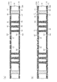
所定の厚さのコア基板31に貫通孔32を形成する。貫通孔32の形成には、例えばレーザ加工機やドリル機を用いることができる。例えば、レーザ加工機により貫通孔32を形成した場合、デスミア処理を行い、貫通孔32内に残留する樹脂スミア等を除去する。デスミア処理として、例えば過マンガン酸カリウム等を用いることができる。
図9(b)に示す工程では、配線基板20のパッドP2上にバンプ96を形成する。また、図9(b)に示す工程では、回路形成面に形成された接続端子92と、その接続端子92の下面に形成された接合部材93とを有する半導体チップ91を準備する。続いて、パッドP1上に、半導体チップ91をフリップチップ接合する。
以上の製造工程により、図3に示した半導体装置90を製造することができる。
(1)開口部34の各角部の周囲に、その角部を構成する開口部34の2つの辺に沿ってL字形に連続して形成された貫通孔35(貫通孔36)を開口部34と離間して形成し、その貫通孔35を充填する絶縁材60を形成した。これにより、絶縁材60の熱硬化後の冷却時に、開口部34の角部における外周縁が外側に引っ張られるため、応力の集中する電子部品50の角部にかかる圧縮応力を緩和することができる。したがって、その圧縮応力に起因して電子部品50の周辺が座屈変形することを抑制でき、絶縁材60の第1面60A及び第2面60Bに凹凸が形成されることを抑制できる。
尚、上記実施形態は、以下の態様で実施してもよい。
・上記実施形態に対し、配線基板20に実装される半導体チップ91の数、その半導体チップ91の実装の形態(例えば、フリップチップ実装、ワイヤボンディングによる実装、又はこれらの組み合わせ)を適宜変更してもよい。
・上記実施形態の電子部品50としては、半導体チップに限らず、チップコンデンサ、チップ抵抗、インダクタ、薄膜コンデンサ等を採用してもよい。
・上記各実施形態並びに各変形例は適宜組み合わせてもよい。
21 コア部
22,23 配線部
31 コア基板
31A 第1面
31B 第2面
31D 橋部
34 開口部
35 貫通孔
36 貫通孔(第1貫通孔)
37 貫通孔(第2貫通孔)
50 電子部品
60 絶縁材
90 半導体装置
91 半導体チップ
100 フィルム
101,102 絶縁樹脂
Claims (10)
- コア基板と、
前記コア基板の第1面と該第1面と反対側の第2面との間を貫通し、平面形状が矩形状に形成された開口部と、
前記コア基板の第1面と第2面との間を貫通し、前記開口部と離間して形成された複数の第1貫通孔と、
前記開口部内に配置された電子部品と、
前記第1貫通孔に充填された第1絶縁材と、
前記開口部の内面と前記電子部品との間に充填された第2絶縁材と、を有し、
前記第1貫通孔は、平面視において、前記開口部の角部の周囲に、前記角部を構成する前記開口部の2つの辺に沿ってL字形に連続して形成されていること、
を特徴とする配線基板。 - 前記コア基板の第1面と第2面との間を貫通し、前記開口部及び前記第1貫通孔と離間して形成された複数の第2貫通孔を有し、
前記複数の第2貫通孔は、平面視において、隣接する前記第1貫通孔の間に、前記開口部の各辺に沿って並設され、
前記各第2貫通孔は、対向する前記辺に沿って長手が延びる長孔状に形成され、
前記第1絶縁材は、前記第2貫通孔に充填されていること、
を特徴とする請求項1に記載の配線基板。 - 前記開口部の各辺の周囲に複数列の前記第2貫通孔が配列され、
前記コア基板は、各列に配置された前記第2貫通孔同士の間に設けられた橋部を有し、
前記第2貫通孔の短手方向に隣接する2列の前記第2貫通孔は、前記2列のうち一方の列に設けられた前記橋部と、前記2列のうち他方の列に設けられた前記第2貫通孔とが対向するように配列されていることを特徴とする請求項2に記載の配線基板。 - 前記開口部の各辺の周囲に複数列の前記第2貫通孔が配列され、
前記第2貫通孔の短手方向に隣接する2つの前記第2貫通孔の間の長さは、前記第2貫通孔の短手方向の長さと同じ、又は前記第2貫通孔の短手方向の長さよりも長いこと、
を特徴とする請求項2又は3に記載の配線基板。 - 前記開口部の各辺の周囲にM列の前記第2貫通孔が配列され、前記開口部の各角部の周囲に前記M列よりも多いN列の前記第1貫通孔が配列されていること、
を特徴とする請求項2〜4のいずれか一項に記載の配線基板。 - 前記第1貫通孔の幅は、前記第2貫通孔の短手方向の長さよりも広く設定されていること、
を特徴とする請求項2〜5のいずれか一項に記載の配線基板。 - 前記第1絶縁材の熱膨張率は、前記コア基板の熱膨張率よりも高いこと、
を特徴とする請求項1〜6のいずれか一項に記載の配線基板。 - 前記第1絶縁材の弾性率は、前記コア基板の弾性率よりも低いこと、
を特徴とする請求項1〜7のいずれか一項に記載の配線基板。 - 請求項1〜8のいずれか一項に記載の配線基板と、
前記コア基板の第1面側に形成された配線部に実装された半導体チップと、を有し、
前記第1貫通孔は、前記コア基板の第2面側から前記コア基板の第1面側に向かうに連れて幅が小さくなるように形成されていること、
を特徴とする半導体装置。 - コア基板を準備する工程と、
前記コア基板の第1面と該第1面と反対側の第2面との間を貫通する開口部と、前記コア基板の第1面と第2面との間を貫通する第1貫通孔とを互いに離間して形成する工程と、
前記開口部を覆うフィルムを、前記コア基板の第1面側に貼着する工程と、
前記開口部内に電子部品を配置し、前記電子部品を前記フィルム上に固定する工程と、
前記第1貫通孔を充填する第1絶縁材を形成する工程と、
前記開口部を充填し、前記電子部品を固定する第2絶縁材を形成する工程と、
前記コア基板から前記フィルムを剥離する工程と、を有し、
前記開口部の平面形状は矩形状に形成され、
前記第1貫通孔は、平面視において、前記開口部の角部の周囲に、前記角部を構成する前記開口部の2つの辺に沿ってL字形に連続して形成されること、
を特徴とする配線基板の製造方法。
Priority Applications (2)
| Application Number | Priority Date | Filing Date | Title |
|---|---|---|---|
| JP2016021698A JP6639934B2 (ja) | 2016-02-08 | 2016-02-08 | 配線基板、半導体装置及び配線基板の製造方法 |
| US15/425,390 US9799596B2 (en) | 2016-02-08 | 2017-02-06 | Wiring substrate and semiconductor device |
Applications Claiming Priority (1)
| Application Number | Priority Date | Filing Date | Title |
|---|---|---|---|
| JP2016021698A JP6639934B2 (ja) | 2016-02-08 | 2016-02-08 | 配線基板、半導体装置及び配線基板の製造方法 |
Publications (2)
| Publication Number | Publication Date |
|---|---|
| JP2017143096A true JP2017143096A (ja) | 2017-08-17 |
| JP6639934B2 JP6639934B2 (ja) | 2020-02-05 |
Family
ID=59498073
Family Applications (1)
| Application Number | Title | Priority Date | Filing Date |
|---|---|---|---|
| JP2016021698A Active JP6639934B2 (ja) | 2016-02-08 | 2016-02-08 | 配線基板、半導体装置及び配線基板の製造方法 |
Country Status (2)
| Country | Link |
|---|---|
| US (1) | US9799596B2 (ja) |
| JP (1) | JP6639934B2 (ja) |
Families Citing this family (3)
| Publication number | Priority date | Publication date | Assignee | Title |
|---|---|---|---|---|
| US11270920B2 (en) * | 2018-08-14 | 2022-03-08 | Medtronic, Inc. | Integrated circuit package and method of forming same |
| KR102545168B1 (ko) * | 2019-03-26 | 2023-06-19 | 삼성전자주식회사 | 인터포저 및 이를 포함하는 반도체 패키지 |
| KR20210007217A (ko) * | 2019-07-10 | 2021-01-20 | 삼성전자주식회사 | 인터포저를 포함하는 전자 장치 |
Family Cites Families (4)
| Publication number | Priority date | Publication date | Assignee | Title |
|---|---|---|---|---|
| JP6009228B2 (ja) * | 2012-05-30 | 2016-10-19 | 新光電気工業株式会社 | 電子部品内蔵基板の製造方法 |
| JP6166878B2 (ja) | 2012-08-30 | 2017-07-19 | 新光電気工業株式会社 | 配線基板、及び、配線基板の製造方法 |
| JP5968753B2 (ja) * | 2012-10-15 | 2016-08-10 | 新光電気工業株式会社 | 配線基板 |
| JP6373605B2 (ja) * | 2014-03-05 | 2018-08-15 | 新光電気工業株式会社 | 配線基板、及び、配線基板の製造方法 |
-
2016
- 2016-02-08 JP JP2016021698A patent/JP6639934B2/ja active Active
-
2017
- 2017-02-06 US US15/425,390 patent/US9799596B2/en active Active
Also Published As
| Publication number | Publication date |
|---|---|
| US9799596B2 (en) | 2017-10-24 |
| US20170229388A1 (en) | 2017-08-10 |
| JP6639934B2 (ja) | 2020-02-05 |
Similar Documents
| Publication | Publication Date | Title |
|---|---|---|
| JP6173781B2 (ja) | 配線基板及び配線基板の製造方法 | |
| JP5410660B2 (ja) | 配線基板及びその製造方法と電子部品装置及びその製造方法 | |
| JP5389770B2 (ja) | 電子素子内蔵印刷回路基板及びその製造方法 | |
| US20100208442A1 (en) | Wiring board assembly and manufacturing method thereof | |
| US9951434B2 (en) | Printed wiring board, semiconductor package and method for manufacturing printed wiring board | |
| US10098243B2 (en) | Printed wiring board and semiconductor package | |
| JP2015106615A (ja) | プリント配線板、プリント配線板の製造方法 | |
| WO2007126090A1 (ja) | 回路基板、電子デバイス装置及び回路基板の製造方法 | |
| JP6158601B2 (ja) | 配線基板及び配線基板の製造方法 | |
| JP7202785B2 (ja) | 配線基板及び配線基板の製造方法 | |
| JP2013532901A (ja) | 放熱回路基板及びその製造方法 | |
| JP2017034059A (ja) | プリント配線板、半導体パッケージおよびプリント配線板の製造方法 | |
| JP2015225895A (ja) | プリント配線板および半導体パッケージ、ならびにプリント配線板の製造方法 | |
| JP6228851B2 (ja) | 配線基板、配線基板の製造方法 | |
| KR101139084B1 (ko) | 다층 프린트 기판 및 그 제조 방법 | |
| JP2009252942A (ja) | 部品内蔵配線板、部品内蔵配線板の製造方法 | |
| JP2010226075A (ja) | 配線板及びその製造方法 | |
| JP6639934B2 (ja) | 配線基板、半導体装置及び配線基板の製造方法 | |
| JP2009135391A (ja) | 電子装置およびその製造方法 | |
| US9420696B2 (en) | Method of manufacturing wiring substrate | |
| JP7247046B2 (ja) | 配線基板及び配線基板の製造方法 | |
| JP2011151048A (ja) | 電子部品の製造方法および電子部品 | |
| JP2009231431A (ja) | 多層プリント配線板およびこれを用いた半導体装置 | |
| JP2008311508A (ja) | 電子部品パッケージおよびその製造方法 | |
| JP2002164475A (ja) | 半導体装置 |
Legal Events
| Date | Code | Title | Description |
|---|---|---|---|
| A621 | Written request for application examination |
Free format text: JAPANESE INTERMEDIATE CODE: A621 Effective date: 20181121 |
|
| A977 | Report on retrieval |
Free format text: JAPANESE INTERMEDIATE CODE: A971007 Effective date: 20190807 |
|
| A131 | Notification of reasons for refusal |
Free format text: JAPANESE INTERMEDIATE CODE: A131 Effective date: 20190820 |
|
| A521 | Request for written amendment filed |
Free format text: JAPANESE INTERMEDIATE CODE: A523 Effective date: 20190917 |
|
| TRDD | Decision of grant or rejection written | ||
| A01 | Written decision to grant a patent or to grant a registration (utility model) |
Free format text: JAPANESE INTERMEDIATE CODE: A01 Effective date: 20191210 |
|
| A61 | First payment of annual fees (during grant procedure) |
Free format text: JAPANESE INTERMEDIATE CODE: A61 Effective date: 20191225 |
|
| R150 | Certificate of patent or registration of utility model |
Ref document number: 6639934 Country of ref document: JP Free format text: JAPANESE INTERMEDIATE CODE: R150 |