JP2015186594A - Flexible microwave catheters for natural or artificial lumens - Google Patents
Flexible microwave catheters for natural or artificial lumens Download PDFInfo
- Publication number
- JP2015186594A JP2015186594A JP2015117544A JP2015117544A JP2015186594A JP 2015186594 A JP2015186594 A JP 2015186594A JP 2015117544 A JP2015117544 A JP 2015117544A JP 2015117544 A JP2015117544 A JP 2015117544A JP 2015186594 A JP2015186594 A JP 2015186594A
- Authority
- JP
- Japan
- Prior art keywords
- radiating portion
- flexible
- catheter
- fluid
- flexible microwave
- Prior art date
- Legal status (The legal status is an assumption and is not a legal conclusion. Google has not performed a legal analysis and makes no representation as to the accuracy of the status listed.)
- Granted
Links
- 239000004020 conductor Substances 0.000 claims abstract description 255
- 230000005855 radiation Effects 0.000 claims description 33
- 230000008878 coupling Effects 0.000 claims description 20
- 238000010168 coupling process Methods 0.000 claims description 20
- 238000005859 coupling reaction Methods 0.000 claims description 20
- 230000033001 locomotion Effects 0.000 claims description 9
- 230000001939 inductive effect Effects 0.000 claims description 3
- 210000005036 nerve Anatomy 0.000 abstract description 34
- 230000006378 damage Effects 0.000 abstract description 10
- 239000012212 insulator Substances 0.000 abstract description 9
- 230000002889 sympathetic effect Effects 0.000 abstract description 6
- 239000012530 fluid Substances 0.000 description 267
- 210000002254 renal artery Anatomy 0.000 description 111
- 210000001519 tissue Anatomy 0.000 description 73
- 238000000034 method Methods 0.000 description 68
- 230000002638 denervation Effects 0.000 description 58
- 239000000463 material Substances 0.000 description 32
- 239000002826 coolant Substances 0.000 description 27
- 210000003484 anatomy Anatomy 0.000 description 25
- 238000001816 cooling Methods 0.000 description 25
- 230000005672 electromagnetic field Effects 0.000 description 24
- 239000012528 membrane Substances 0.000 description 20
- 238000010438 heat treatment Methods 0.000 description 19
- 238000002679 ablation Methods 0.000 description 17
- 239000008280 blood Substances 0.000 description 17
- 210000004369 blood Anatomy 0.000 description 17
- 238000007789 sealing Methods 0.000 description 16
- 230000009977 dual effect Effects 0.000 description 15
- 239000012809 cooling fluid Substances 0.000 description 14
- 230000001965 increasing effect Effects 0.000 description 12
- 230000036772 blood pressure Effects 0.000 description 11
- 238000004891 communication Methods 0.000 description 11
- 239000002989 correction material Substances 0.000 description 11
- 230000007246 mechanism Effects 0.000 description 11
- 210000005166 vasculature Anatomy 0.000 description 10
- 239000011248 coating agent Substances 0.000 description 9
- 238000000576 coating method Methods 0.000 description 9
- 239000007788 liquid Substances 0.000 description 9
- 230000004044 response Effects 0.000 description 9
- 230000017531 blood circulation Effects 0.000 description 8
- 210000001105 femoral artery Anatomy 0.000 description 8
- 210000003734 kidney Anatomy 0.000 description 8
- 239000011295 pitch Substances 0.000 description 8
- 238000013459 approach Methods 0.000 description 7
- 210000004204 blood vessel Anatomy 0.000 description 7
- 230000008859 change Effects 0.000 description 7
- 239000003989 dielectric material Substances 0.000 description 7
- 229910052751 metal Inorganic materials 0.000 description 7
- 239000002184 metal Substances 0.000 description 7
- 230000002829 reductive effect Effects 0.000 description 7
- 230000005540 biological transmission Effects 0.000 description 6
- 238000013461 design Methods 0.000 description 6
- 210000002216 heart Anatomy 0.000 description 6
- 238000004519 manufacturing process Methods 0.000 description 6
- 229920001343 polytetrafluoroethylene Polymers 0.000 description 6
- 239000004810 polytetrafluoroethylene Substances 0.000 description 6
- 238000001356 surgical procedure Methods 0.000 description 6
- FAPWRFPIFSIZLT-UHFFFAOYSA-M Sodium chloride Chemical compound [Na+].[Cl-] FAPWRFPIFSIZLT-UHFFFAOYSA-M 0.000 description 5
- 210000001367 artery Anatomy 0.000 description 5
- 210000001124 body fluid Anatomy 0.000 description 5
- 238000010586 diagram Methods 0.000 description 5
- 230000006870 function Effects 0.000 description 5
- 238000012544 monitoring process Methods 0.000 description 5
- 239000012811 non-conductive material Substances 0.000 description 5
- 230000036961 partial effect Effects 0.000 description 5
- -1 polytetrafluoroethylene Polymers 0.000 description 5
- 210000002460 smooth muscle Anatomy 0.000 description 5
- 239000011780 sodium chloride Substances 0.000 description 5
- XLYOFNOQVPJJNP-UHFFFAOYSA-N water Substances O XLYOFNOQVPJJNP-UHFFFAOYSA-N 0.000 description 5
- CURLTUGMZLYLDI-UHFFFAOYSA-N Carbon dioxide Chemical compound O=C=O CURLTUGMZLYLDI-UHFFFAOYSA-N 0.000 description 4
- 206010053567 Coagulopathies Diseases 0.000 description 4
- BQCADISMDOOEFD-UHFFFAOYSA-N Silver Chemical compound [Ag] BQCADISMDOOEFD-UHFFFAOYSA-N 0.000 description 4
- QVGXLLKOCUKJST-UHFFFAOYSA-N atomic oxygen Chemical compound [O] QVGXLLKOCUKJST-UHFFFAOYSA-N 0.000 description 4
- 239000010839 body fluid Substances 0.000 description 4
- 230000035602 clotting Effects 0.000 description 4
- 238000009826 distribution Methods 0.000 description 4
- 210000004392 genitalia Anatomy 0.000 description 4
- 230000001976 improved effect Effects 0.000 description 4
- 238000007726 management method Methods 0.000 description 4
- 239000000203 mixture Substances 0.000 description 4
- 210000003097 mucus Anatomy 0.000 description 4
- 230000008904 neural response Effects 0.000 description 4
- 229910052760 oxygen Inorganic materials 0.000 description 4
- 239000001301 oxygen Substances 0.000 description 4
- 230000035479 physiological effects, processes and functions Effects 0.000 description 4
- 238000002310 reflectometry Methods 0.000 description 4
- 229910052709 silver Inorganic materials 0.000 description 4
- 239000004332 silver Substances 0.000 description 4
- 210000003708 urethra Anatomy 0.000 description 4
- 210000001835 viscera Anatomy 0.000 description 4
- 206010020772 Hypertension Diseases 0.000 description 3
- 239000003570 air Substances 0.000 description 3
- 230000015572 biosynthetic process Effects 0.000 description 3
- 210000000621 bronchi Anatomy 0.000 description 3
- 230000000694 effects Effects 0.000 description 3
- 210000003238 esophagus Anatomy 0.000 description 3
- 239000010408 film Substances 0.000 description 3
- 238000002594 fluoroscopy Methods 0.000 description 3
- 239000011888 foil Substances 0.000 description 3
- 238000003780 insertion Methods 0.000 description 3
- 230000037431 insertion Effects 0.000 description 3
- 238000009434 installation Methods 0.000 description 3
- 230000000670 limiting effect Effects 0.000 description 3
- 229910001000 nickel titanium Inorganic materials 0.000 description 3
- 229920000052 poly(p-xylylene) Polymers 0.000 description 3
- 229920000139 polyethylene terephthalate Polymers 0.000 description 3
- 239000005020 polyethylene terephthalate Substances 0.000 description 3
- 229920000642 polymer Polymers 0.000 description 3
- 230000029058 respiratory gaseous exchange Effects 0.000 description 3
- 210000002345 respiratory system Anatomy 0.000 description 3
- 210000002784 stomach Anatomy 0.000 description 3
- 230000002485 urinary effect Effects 0.000 description 3
- 230000002792 vascular Effects 0.000 description 3
- 208000006545 Chronic Obstructive Pulmonary Disease Diseases 0.000 description 2
- 102000016942 Elastin Human genes 0.000 description 2
- 108010014258 Elastin Proteins 0.000 description 2
- 208000031481 Pathologic Constriction Diseases 0.000 description 2
- 229920006362 Teflon® Polymers 0.000 description 2
- 208000007536 Thrombosis Diseases 0.000 description 2
- 210000000709 aorta Anatomy 0.000 description 2
- 230000006399 behavior Effects 0.000 description 2
- 230000033228 biological regulation Effects 0.000 description 2
- 230000003139 buffering effect Effects 0.000 description 2
- 229910002092 carbon dioxide Inorganic materials 0.000 description 2
- 239000001569 carbon dioxide Substances 0.000 description 2
- 230000001684 chronic effect Effects 0.000 description 2
- 230000008602 contraction Effects 0.000 description 2
- 230000007423 decrease Effects 0.000 description 2
- 238000000151 deposition Methods 0.000 description 2
- 230000008021 deposition Effects 0.000 description 2
- 238000011161 development Methods 0.000 description 2
- 230000018109 developmental process Effects 0.000 description 2
- 210000000613 ear canal Anatomy 0.000 description 2
- 229920002549 elastin Polymers 0.000 description 2
- 230000002496 gastric effect Effects 0.000 description 2
- 238000003384 imaging method Methods 0.000 description 2
- 238000009413 insulation Methods 0.000 description 2
- 210000000936 intestine Anatomy 0.000 description 2
- 238000011068 loading method Methods 0.000 description 2
- 210000004072 lung Anatomy 0.000 description 2
- 230000001537 neural effect Effects 0.000 description 2
- HLXZNVUGXRDIFK-UHFFFAOYSA-N nickel titanium Chemical compound [Ti].[Ti].[Ti].[Ti].[Ti].[Ti].[Ti].[Ti].[Ti].[Ti].[Ti].[Ni].[Ni].[Ni].[Ni].[Ni].[Ni].[Ni].[Ni].[Ni].[Ni].[Ni].[Ni].[Ni].[Ni] HLXZNVUGXRDIFK-UHFFFAOYSA-N 0.000 description 2
- 210000000056 organ Anatomy 0.000 description 2
- 230000002093 peripheral effect Effects 0.000 description 2
- 238000007747 plating Methods 0.000 description 2
- BASFCYQUMIYNBI-UHFFFAOYSA-N platinum Chemical compound [Pt] BASFCYQUMIYNBI-UHFFFAOYSA-N 0.000 description 2
- 230000001902 propagating effect Effects 0.000 description 2
- 230000008660 renal denervation Effects 0.000 description 2
- 230000000241 respiratory effect Effects 0.000 description 2
- 239000000523 sample Substances 0.000 description 2
- 239000012781 shape memory material Substances 0.000 description 2
- 229920000431 shape-memory polymer Polymers 0.000 description 2
- 238000007493 shaping process Methods 0.000 description 2
- 230000036262 stenosis Effects 0.000 description 2
- 208000037804 stenosis Diseases 0.000 description 2
- 239000000126 substance Substances 0.000 description 2
- 238000000427 thin-film deposition Methods 0.000 description 2
- 230000007704 transition Effects 0.000 description 2
- 210000003932 urinary bladder Anatomy 0.000 description 2
- 210000004291 uterus Anatomy 0.000 description 2
- 210000003462 vein Anatomy 0.000 description 2
- 238000003466 welding Methods 0.000 description 2
- 241001631457 Cannula Species 0.000 description 1
- RYGMFSIKBFXOCR-UHFFFAOYSA-N Copper Chemical compound [Cu] RYGMFSIKBFXOCR-UHFFFAOYSA-N 0.000 description 1
- 208000007342 Diabetic Nephropathies Diseases 0.000 description 1
- 208000005189 Embolism Diseases 0.000 description 1
- 206010014561 Emphysema Diseases 0.000 description 1
- PXGOKWXKJXAPGV-UHFFFAOYSA-N Fluorine Chemical compound FF PXGOKWXKJXAPGV-UHFFFAOYSA-N 0.000 description 1
- WQZGKKKJIJFFOK-GASJEMHNSA-N Glucose Natural products OC[C@H]1OC(O)[C@H](O)[C@@H](O)[C@@H]1O WQZGKKKJIJFFOK-GASJEMHNSA-N 0.000 description 1
- 206010019280 Heart failures Diseases 0.000 description 1
- 208000001953 Hypotension Diseases 0.000 description 1
- 208000001145 Metabolic Syndrome Diseases 0.000 description 1
- 239000004642 Polyimide Substances 0.000 description 1
- 208000001647 Renal Insufficiency Diseases 0.000 description 1
- 241000219793 Trifolium Species 0.000 description 1
- 201000000690 abdominal obesity-metabolic syndrome Diseases 0.000 description 1
- 238000010521 absorption reaction Methods 0.000 description 1
- 239000000853 adhesive Substances 0.000 description 1
- 238000004026 adhesive bonding Methods 0.000 description 1
- 230000001070 adhesive effect Effects 0.000 description 1
- 229910045601 alloy Inorganic materials 0.000 description 1
- 239000000956 alloy Substances 0.000 description 1
- 238000002583 angiography Methods 0.000 description 1
- 210000000436 anus Anatomy 0.000 description 1
- 210000000702 aorta abdominal Anatomy 0.000 description 1
- 208000006673 asthma Diseases 0.000 description 1
- 230000004323 axial length Effects 0.000 description 1
- 229910052788 barium Inorganic materials 0.000 description 1
- DSAJWYNOEDNPEQ-UHFFFAOYSA-N barium atom Chemical compound [Ba] DSAJWYNOEDNPEQ-UHFFFAOYSA-N 0.000 description 1
- 238000005452 bending Methods 0.000 description 1
- 230000008901 benefit Effects 0.000 description 1
- 210000000941 bile Anatomy 0.000 description 1
- 210000000013 bile duct Anatomy 0.000 description 1
- 239000012620 biological material Substances 0.000 description 1
- 230000000903 blocking effect Effects 0.000 description 1
- 230000023555 blood coagulation Effects 0.000 description 1
- 238000005219 brazing Methods 0.000 description 1
- 210000005242 cardiac chamber Anatomy 0.000 description 1
- 210000000845 cartilage Anatomy 0.000 description 1
- 239000000919 ceramic Substances 0.000 description 1
- 210000003679 cervix uteri Anatomy 0.000 description 1
- 230000004087 circulation Effects 0.000 description 1
- 230000007012 clinical effect Effects 0.000 description 1
- 210000001072 colon Anatomy 0.000 description 1
- 239000002131 composite material Substances 0.000 description 1
- 230000006835 compression Effects 0.000 description 1
- 238000007906 compression Methods 0.000 description 1
- 239000012141 concentrate Substances 0.000 description 1
- 210000002808 connective tissue Anatomy 0.000 description 1
- 229910052802 copper Inorganic materials 0.000 description 1
- 239000010949 copper Substances 0.000 description 1
- 238000005520 cutting process Methods 0.000 description 1
- 231100000433 cytotoxic Toxicity 0.000 description 1
- 230000001472 cytotoxic effect Effects 0.000 description 1
- 230000034994 death Effects 0.000 description 1
- 230000003247 decreasing effect Effects 0.000 description 1
- 239000008367 deionised water Substances 0.000 description 1
- 229910021641 deionized water Inorganic materials 0.000 description 1
- 230000001419 dependent effect Effects 0.000 description 1
- 208000033679 diabetic kidney disease Diseases 0.000 description 1
- 238000002059 diagnostic imaging Methods 0.000 description 1
- 230000000916 dilatatory effect Effects 0.000 description 1
- 201000010099 disease Diseases 0.000 description 1
- 208000037265 diseases, disorders, signs and symptoms Diseases 0.000 description 1
- 239000013013 elastic material Substances 0.000 description 1
- 230000005611 electricity Effects 0.000 description 1
- 230000003073 embolic effect Effects 0.000 description 1
- 238000005530 etching Methods 0.000 description 1
- HQQADJVZYDDRJT-UHFFFAOYSA-N ethene;prop-1-ene Chemical group C=C.CC=C HQQADJVZYDDRJT-UHFFFAOYSA-N 0.000 description 1
- 238000002474 experimental method Methods 0.000 description 1
- 238000001125 extrusion Methods 0.000 description 1
- 230000002349 favourable effect Effects 0.000 description 1
- 210000004996 female reproductive system Anatomy 0.000 description 1
- 230000005294 ferromagnetic effect Effects 0.000 description 1
- 238000011049 filling Methods 0.000 description 1
- 229910052731 fluorine Inorganic materials 0.000 description 1
- 239000011737 fluorine Substances 0.000 description 1
- 210000000232 gallbladder Anatomy 0.000 description 1
- 239000007789 gas Substances 0.000 description 1
- 210000005095 gastrointestinal system Anatomy 0.000 description 1
- 210000004907 gland Anatomy 0.000 description 1
- 239000008103 glucose Substances 0.000 description 1
- 239000003292 glue Substances 0.000 description 1
- PCHJSUWPFVWCPO-UHFFFAOYSA-N gold Chemical compound [Au] PCHJSUWPFVWCPO-UHFFFAOYSA-N 0.000 description 1
- 229910052737 gold Inorganic materials 0.000 description 1
- 239000010931 gold Substances 0.000 description 1
- 208000019622 heart disease Diseases 0.000 description 1
- 230000020169 heat generation Effects 0.000 description 1
- 230000036543 hypotension Effects 0.000 description 1
- 238000011065 in-situ storage Methods 0.000 description 1
- 238000007373 indentation Methods 0.000 description 1
- 230000002401 inhibitory effect Effects 0.000 description 1
- 201000006370 kidney failure Diseases 0.000 description 1
- 210000002429 large intestine Anatomy 0.000 description 1
- 231100000518 lethal Toxicity 0.000 description 1
- 230000001665 lethal effect Effects 0.000 description 1
- 210000004185 liver Anatomy 0.000 description 1
- 208000037841 lung tumor Diseases 0.000 description 1
- 210000004995 male reproductive system Anatomy 0.000 description 1
- 238000005259 measurement Methods 0.000 description 1
- 230000008450 motivation Effects 0.000 description 1
- 210000000214 mouth Anatomy 0.000 description 1
- 210000004877 mucosa Anatomy 0.000 description 1
- 210000003928 nasal cavity Anatomy 0.000 description 1
- 230000008035 nerve activity Effects 0.000 description 1
- 210000001672 ovary Anatomy 0.000 description 1
- 210000003101 oviduct Anatomy 0.000 description 1
- 210000000496 pancreas Anatomy 0.000 description 1
- 230000037361 pathway Effects 0.000 description 1
- 210000003800 pharynx Anatomy 0.000 description 1
- 239000004033 plastic Substances 0.000 description 1
- 229920003023 plastic Polymers 0.000 description 1
- 229910052697 platinum Inorganic materials 0.000 description 1
- 229920001721 polyimide Polymers 0.000 description 1
- 239000002861 polymer material Substances 0.000 description 1
- 229920002635 polyurethane Polymers 0.000 description 1
- 239000004814 polyurethane Substances 0.000 description 1
- 230000001737 promoting effect Effects 0.000 description 1
- 230000000644 propagated effect Effects 0.000 description 1
- 210000002307 prostate Anatomy 0.000 description 1
- 102000004169 proteins and genes Human genes 0.000 description 1
- 108090000623 proteins and genes Proteins 0.000 description 1
- 210000000664 rectum Anatomy 0.000 description 1
- 230000009467 reduction Effects 0.000 description 1
- 230000008439 repair process Effects 0.000 description 1
- 230000003252 repetitive effect Effects 0.000 description 1
- 230000036387 respiratory rate Effects 0.000 description 1
- 150000003839 salts Chemical class 0.000 description 1
- 238000000926 separation method Methods 0.000 description 1
- 229910001285 shape-memory alloy Inorganic materials 0.000 description 1
- 201000002859 sleep apnea Diseases 0.000 description 1
- 210000000813 small intestine Anatomy 0.000 description 1
- 238000005476 soldering Methods 0.000 description 1
- 210000000952 spleen Anatomy 0.000 description 1
- 229910001220 stainless steel Inorganic materials 0.000 description 1
- 239000010935 stainless steel Substances 0.000 description 1
- 238000003860 storage Methods 0.000 description 1
- 210000000434 stratum corneum Anatomy 0.000 description 1
- 230000002459 sustained effect Effects 0.000 description 1
- 230000035488 systolic blood pressure Effects 0.000 description 1
- 230000008685 targeting Effects 0.000 description 1
- 210000004876 tela submucosa Anatomy 0.000 description 1
- 210000001550 testis Anatomy 0.000 description 1
- 230000003685 thermal hair damage Effects 0.000 description 1
- 238000000015 thermotherapy Methods 0.000 description 1
- 230000000451 tissue damage Effects 0.000 description 1
- 231100000827 tissue damage Toxicity 0.000 description 1
- 231100000331 toxic Toxicity 0.000 description 1
- 230000002588 toxic effect Effects 0.000 description 1
- 210000003437 trachea Anatomy 0.000 description 1
- 238000002627 tracheal intubation Methods 0.000 description 1
- 230000017105 transposition Effects 0.000 description 1
- 238000002604 ultrasonography Methods 0.000 description 1
- 238000009827 uniform distribution Methods 0.000 description 1
- 210000000626 ureter Anatomy 0.000 description 1
- 210000002700 urine Anatomy 0.000 description 1
- 210000001215 vagina Anatomy 0.000 description 1
- 210000001177 vas deferen Anatomy 0.000 description 1
- 230000035899 viability Effects 0.000 description 1
Images


Classifications
-
- A—HUMAN NECESSITIES
- A61—MEDICAL OR VETERINARY SCIENCE; HYGIENE
- A61B—DIAGNOSIS; SURGERY; IDENTIFICATION
- A61B18/00—Surgical instruments, devices or methods for transferring non-mechanical forms of energy to or from the body
- A61B18/18—Surgical instruments, devices or methods for transferring non-mechanical forms of energy to or from the body by applying electromagnetic radiation, e.g. microwaves
- A61B18/1815—Surgical instruments, devices or methods for transferring non-mechanical forms of energy to or from the body by applying electromagnetic radiation, e.g. microwaves using microwaves
-
- A—HUMAN NECESSITIES
- A61—MEDICAL OR VETERINARY SCIENCE; HYGIENE
- A61B—DIAGNOSIS; SURGERY; IDENTIFICATION
- A61B17/00—Surgical instruments, devices or methods, e.g. tourniquets
- A61B17/00234—Surgical instruments, devices or methods, e.g. tourniquets for minimally invasive surgery
-
- A—HUMAN NECESSITIES
- A61—MEDICAL OR VETERINARY SCIENCE; HYGIENE
- A61B—DIAGNOSIS; SURGERY; IDENTIFICATION
- A61B18/00—Surgical instruments, devices or methods for transferring non-mechanical forms of energy to or from the body
- A61B18/04—Surgical instruments, devices or methods for transferring non-mechanical forms of energy to or from the body by heating
- A61B18/12—Surgical instruments, devices or methods for transferring non-mechanical forms of energy to or from the body by heating by passing a current through the tissue to be heated, e.g. high-frequency current
- A61B18/14—Probes or electrodes therefor
- A61B18/1492—Probes or electrodes therefor having a flexible, catheter-like structure, e.g. for heart ablation
-
- A—HUMAN NECESSITIES
- A61—MEDICAL OR VETERINARY SCIENCE; HYGIENE
- A61B—DIAGNOSIS; SURGERY; IDENTIFICATION
- A61B18/00—Surgical instruments, devices or methods for transferring non-mechanical forms of energy to or from the body
- A61B18/18—Surgical instruments, devices or methods for transferring non-mechanical forms of energy to or from the body by applying electromagnetic radiation, e.g. microwaves
-
- A—HUMAN NECESSITIES
- A61—MEDICAL OR VETERINARY SCIENCE; HYGIENE
- A61N—ELECTROTHERAPY; MAGNETOTHERAPY; RADIATION THERAPY; ULTRASOUND THERAPY
- A61N5/00—Radiation therapy
- A61N5/02—Radiation therapy using microwaves
- A61N5/022—Apparatus adapted for a specific treatment
-
- A—HUMAN NECESSITIES
- A61—MEDICAL OR VETERINARY SCIENCE; HYGIENE
- A61B—DIAGNOSIS; SURGERY; IDENTIFICATION
- A61B17/00—Surgical instruments, devices or methods, e.g. tourniquets
- A61B17/00234—Surgical instruments, devices or methods, e.g. tourniquets for minimally invasive surgery
- A61B2017/00292—Surgical instruments, devices or methods, e.g. tourniquets for minimally invasive surgery mounted on or guided by flexible, e.g. catheter-like, means
- A61B2017/003—Steerable
- A61B2017/00318—Steering mechanisms
- A61B2017/00323—Cables or rods
-
- A—HUMAN NECESSITIES
- A61—MEDICAL OR VETERINARY SCIENCE; HYGIENE
- A61B—DIAGNOSIS; SURGERY; IDENTIFICATION
- A61B18/00—Surgical instruments, devices or methods for transferring non-mechanical forms of energy to or from the body
- A61B2018/00005—Cooling or heating of the probe or tissue immediately surrounding the probe
- A61B2018/00011—Cooling or heating of the probe or tissue immediately surrounding the probe with fluids
- A61B2018/00023—Cooling or heating of the probe or tissue immediately surrounding the probe with fluids closed, i.e. without wound contact by the fluid
-
- A—HUMAN NECESSITIES
- A61—MEDICAL OR VETERINARY SCIENCE; HYGIENE
- A61B—DIAGNOSIS; SURGERY; IDENTIFICATION
- A61B18/00—Surgical instruments, devices or methods for transferring non-mechanical forms of energy to or from the body
- A61B2018/00053—Mechanical features of the instrument of device
- A61B2018/00059—Material properties
- A61B2018/00071—Electrical conductivity
- A61B2018/00077—Electrical conductivity high, i.e. electrically conducting
-
- A—HUMAN NECESSITIES
- A61—MEDICAL OR VETERINARY SCIENCE; HYGIENE
- A61B—DIAGNOSIS; SURGERY; IDENTIFICATION
- A61B18/00—Surgical instruments, devices or methods for transferring non-mechanical forms of energy to or from the body
- A61B2018/00053—Mechanical features of the instrument of device
- A61B2018/00172—Connectors and adapters therefor
-
- A—HUMAN NECESSITIES
- A61—MEDICAL OR VETERINARY SCIENCE; HYGIENE
- A61B—DIAGNOSIS; SURGERY; IDENTIFICATION
- A61B18/00—Surgical instruments, devices or methods for transferring non-mechanical forms of energy to or from the body
- A61B2018/00053—Mechanical features of the instrument of device
- A61B2018/00214—Expandable means emitting energy, e.g. by elements carried thereon
- A61B2018/0022—Balloons
- A61B2018/00226—Balloons extending from a surface, i.e. Blisters
-
- A—HUMAN NECESSITIES
- A61—MEDICAL OR VETERINARY SCIENCE; HYGIENE
- A61B—DIAGNOSIS; SURGERY; IDENTIFICATION
- A61B18/00—Surgical instruments, devices or methods for transferring non-mechanical forms of energy to or from the body
- A61B2018/00053—Mechanical features of the instrument of device
- A61B2018/00214—Expandable means emitting energy, e.g. by elements carried thereon
- A61B2018/0022—Balloons
- A61B2018/00232—Balloons having an irregular shape
-
- A—HUMAN NECESSITIES
- A61—MEDICAL OR VETERINARY SCIENCE; HYGIENE
- A61B—DIAGNOSIS; SURGERY; IDENTIFICATION
- A61B18/00—Surgical instruments, devices or methods for transferring non-mechanical forms of energy to or from the body
- A61B2018/00053—Mechanical features of the instrument of device
- A61B2018/00214—Expandable means emitting energy, e.g. by elements carried thereon
- A61B2018/0022—Balloons
- A61B2018/0025—Multiple balloons
-
- A—HUMAN NECESSITIES
- A61—MEDICAL OR VETERINARY SCIENCE; HYGIENE
- A61B—DIAGNOSIS; SURGERY; IDENTIFICATION
- A61B18/00—Surgical instruments, devices or methods for transferring non-mechanical forms of energy to or from the body
- A61B2018/00053—Mechanical features of the instrument of device
- A61B2018/00214—Expandable means emitting energy, e.g. by elements carried thereon
- A61B2018/00267—Expandable means emitting energy, e.g. by elements carried thereon having a basket shaped structure
-
- A—HUMAN NECESSITIES
- A61—MEDICAL OR VETERINARY SCIENCE; HYGIENE
- A61B—DIAGNOSIS; SURGERY; IDENTIFICATION
- A61B18/00—Surgical instruments, devices or methods for transferring non-mechanical forms of energy to or from the body
- A61B2018/00053—Mechanical features of the instrument of device
- A61B2018/00273—Anchoring means for temporary attachment of a device to tissue
- A61B2018/00279—Anchoring means for temporary attachment of a device to tissue deployable
- A61B2018/00285—Balloons
-
- A—HUMAN NECESSITIES
- A61—MEDICAL OR VETERINARY SCIENCE; HYGIENE
- A61B—DIAGNOSIS; SURGERY; IDENTIFICATION
- A61B18/00—Surgical instruments, devices or methods for transferring non-mechanical forms of energy to or from the body
- A61B2018/00315—Surgical instruments, devices or methods for transferring non-mechanical forms of energy to or from the body for treatment of particular body parts
- A61B2018/00345—Vascular system
-
- A—HUMAN NECESSITIES
- A61—MEDICAL OR VETERINARY SCIENCE; HYGIENE
- A61B—DIAGNOSIS; SURGERY; IDENTIFICATION
- A61B18/00—Surgical instruments, devices or methods for transferring non-mechanical forms of energy to or from the body
- A61B2018/00315—Surgical instruments, devices or methods for transferring non-mechanical forms of energy to or from the body for treatment of particular body parts
- A61B2018/00434—Neural system
-
- A—HUMAN NECESSITIES
- A61—MEDICAL OR VETERINARY SCIENCE; HYGIENE
- A61B—DIAGNOSIS; SURGERY; IDENTIFICATION
- A61B18/00—Surgical instruments, devices or methods for transferring non-mechanical forms of energy to or from the body
- A61B2018/00315—Surgical instruments, devices or methods for transferring non-mechanical forms of energy to or from the body for treatment of particular body parts
- A61B2018/00505—Urinary tract
- A61B2018/00511—Kidney
-
- A—HUMAN NECESSITIES
- A61—MEDICAL OR VETERINARY SCIENCE; HYGIENE
- A61B—DIAGNOSIS; SURGERY; IDENTIFICATION
- A61B18/00—Surgical instruments, devices or methods for transferring non-mechanical forms of energy to or from the body
- A61B2018/00571—Surgical instruments, devices or methods for transferring non-mechanical forms of energy to or from the body for achieving a particular surgical effect
- A61B2018/00577—Ablation
-
- A—HUMAN NECESSITIES
- A61—MEDICAL OR VETERINARY SCIENCE; HYGIENE
- A61B—DIAGNOSIS; SURGERY; IDENTIFICATION
- A61B18/00—Surgical instruments, devices or methods for transferring non-mechanical forms of energy to or from the body
- A61B2018/00571—Surgical instruments, devices or methods for transferring non-mechanical forms of energy to or from the body for achieving a particular surgical effect
- A61B2018/00595—Cauterization
-
- A—HUMAN NECESSITIES
- A61—MEDICAL OR VETERINARY SCIENCE; HYGIENE
- A61B—DIAGNOSIS; SURGERY; IDENTIFICATION
- A61B18/00—Surgical instruments, devices or methods for transferring non-mechanical forms of energy to or from the body
- A61B2018/00636—Sensing and controlling the application of energy
- A61B2018/00773—Sensed parameters
- A61B2018/00791—Temperature
-
- A—HUMAN NECESSITIES
- A61—MEDICAL OR VETERINARY SCIENCE; HYGIENE
- A61B—DIAGNOSIS; SURGERY; IDENTIFICATION
- A61B18/00—Surgical instruments, devices or methods for transferring non-mechanical forms of energy to or from the body
- A61B2018/00636—Sensing and controlling the application of energy
- A61B2018/00773—Sensed parameters
- A61B2018/00875—Resistance or impedance
-
- A—HUMAN NECESSITIES
- A61—MEDICAL OR VETERINARY SCIENCE; HYGIENE
- A61B—DIAGNOSIS; SURGERY; IDENTIFICATION
- A61B18/00—Surgical instruments, devices or methods for transferring non-mechanical forms of energy to or from the body
- A61B18/18—Surgical instruments, devices or methods for transferring non-mechanical forms of energy to or from the body by applying electromagnetic radiation, e.g. microwaves
- A61B18/1815—Surgical instruments, devices or methods for transferring non-mechanical forms of energy to or from the body by applying electromagnetic radiation, e.g. microwaves using microwaves
- A61B2018/1823—Generators therefor
-
- A—HUMAN NECESSITIES
- A61—MEDICAL OR VETERINARY SCIENCE; HYGIENE
- A61B—DIAGNOSIS; SURGERY; IDENTIFICATION
- A61B18/00—Surgical instruments, devices or methods for transferring non-mechanical forms of energy to or from the body
- A61B18/18—Surgical instruments, devices or methods for transferring non-mechanical forms of energy to or from the body by applying electromagnetic radiation, e.g. microwaves
- A61B18/1815—Surgical instruments, devices or methods for transferring non-mechanical forms of energy to or from the body by applying electromagnetic radiation, e.g. microwaves using microwaves
- A61B2018/183—Surgical instruments, devices or methods for transferring non-mechanical forms of energy to or from the body by applying electromagnetic radiation, e.g. microwaves using microwaves characterised by the type of antenna
- A61B2018/1846—Helical antennas
-
- A—HUMAN NECESSITIES
- A61—MEDICAL OR VETERINARY SCIENCE; HYGIENE
- A61B—DIAGNOSIS; SURGERY; IDENTIFICATION
- A61B18/00—Surgical instruments, devices or methods for transferring non-mechanical forms of energy to or from the body
- A61B18/18—Surgical instruments, devices or methods for transferring non-mechanical forms of energy to or from the body by applying electromagnetic radiation, e.g. microwaves
- A61B18/1815—Surgical instruments, devices or methods for transferring non-mechanical forms of energy to or from the body by applying electromagnetic radiation, e.g. microwaves using microwaves
- A61B2018/1861—Surgical instruments, devices or methods for transferring non-mechanical forms of energy to or from the body by applying electromagnetic radiation, e.g. microwaves using microwaves with an instrument inserted into a body lumen or cavity, e.g. a catheter
-
- A—HUMAN NECESSITIES
- A61—MEDICAL OR VETERINARY SCIENCE; HYGIENE
- A61B—DIAGNOSIS; SURGERY; IDENTIFICATION
- A61B18/00—Surgical instruments, devices or methods for transferring non-mechanical forms of energy to or from the body
- A61B18/18—Surgical instruments, devices or methods for transferring non-mechanical forms of energy to or from the body by applying electromagnetic radiation, e.g. microwaves
- A61B18/1815—Surgical instruments, devices or methods for transferring non-mechanical forms of energy to or from the body by applying electromagnetic radiation, e.g. microwaves using microwaves
- A61B2018/1884—Surgical instruments, devices or methods for transferring non-mechanical forms of energy to or from the body by applying electromagnetic radiation, e.g. microwaves using microwaves with non-uniform emissions
-
- A—HUMAN NECESSITIES
- A61—MEDICAL OR VETERINARY SCIENCE; HYGIENE
- A61B—DIAGNOSIS; SURGERY; IDENTIFICATION
- A61B18/00—Surgical instruments, devices or methods for transferring non-mechanical forms of energy to or from the body
- A61B18/18—Surgical instruments, devices or methods for transferring non-mechanical forms of energy to or from the body by applying electromagnetic radiation, e.g. microwaves
- A61B18/1815—Surgical instruments, devices or methods for transferring non-mechanical forms of energy to or from the body by applying electromagnetic radiation, e.g. microwaves using microwaves
- A61B2018/1892—Details of electrical isolations of the antenna
-
- A—HUMAN NECESSITIES
- A61—MEDICAL OR VETERINARY SCIENCE; HYGIENE
- A61B—DIAGNOSIS; SURGERY; IDENTIFICATION
- A61B90/00—Instruments, implements or accessories specially adapted for surgery or diagnosis and not covered by any of the groups A61B1/00 - A61B50/00, e.g. for luxation treatment or for protecting wound edges
- A61B90/10—Instruments, implements or accessories specially adapted for surgery or diagnosis and not covered by any of the groups A61B1/00 - A61B50/00, e.g. for luxation treatment or for protecting wound edges for stereotaxic surgery, e.g. frame-based stereotaxis
Abstract
Description
本開示は、一般に、天然または人工管腔のための可撓性マイクロ波カテーテル、ならびに関連する組立て方法および使用方法に関する。 The present disclosure relates generally to flexible microwave catheters for natural or artificial lumens, and related methods of assembly and use.
エネルギーに基づく組織処置は、当該技術分野で公知である。様々なタイプのエネルギー(例えば、電気、超音波、マイクロ波、低温、熱、レーザなど)が、組織に適用されて、所望の結果を実現する。マイクロ波エネルギーを体内の天然管腔内、体内の天然もしくは人工管腔を通りアクセス可能な場所、および/または身体構造、例えば内臓もしくは身体構造に効果的に送達させるマイクロ波カテーテルが開示されている。 Energy-based tissue treatment is known in the art. Various types of energy (eg, electricity, ultrasound, microwave, low temperature, heat, laser, etc.) are applied to the tissue to achieve the desired result. Disclosed is a microwave catheter that effectively delivers microwave energy to a natural lumen within the body, a location accessible through a natural or artificial lumen within the body, and / or a body structure, such as a viscera or body structure .
そのような天然管腔の1つの集合としては、胃腸系に関係する管腔(例えば、口、咽頭、食道、胃、膵臓、小腸および大腸、胆管、直腸、および肛門)が挙げられる。天然管腔の別のそのような集合としては、聴覚系(例えば、耳道および耳管)が挙げられる。天然管腔の更に別のそのような集合としては、呼吸器系に関係する管腔(例えば、鼻前庭、鼻腔、副鼻腔、気管、ならびに主および肺葉気管支)が挙げられる。天然管腔の別のそのような集合としては、泌尿器系に関係する管腔(例えば、尿道、膀胱、尿管、前立腺、および腎臓)が挙げられる。天然管腔の別のそのような集合としては、女性生殖器系に関係する管腔(例えば、膣、子宮頸部、子宮、卵管、および卵巣)が挙げられる。天然管腔の別のそのような集合としては、男性生殖器系に関係する管腔(例えば、尿道、射精管、輸精管、および精巣)が挙げられる。他の天然管腔が、血管系に関係する管腔(大動脈、動脈、静脈、心臓の部屋)にアクセスするために、他の手段、例えば一般的な血管内手順を介したアクセスを必要とする場合がある。加えて、血管系に関連する管腔は、全ての内臓/身体構造への経路および/またはアクセス(例えば、心臓、肺、腎臓、肝臓、胃、腸、結腸、脾臓、胆嚢および虫垂へのアクセス)を提供することができる。 One collection of such natural lumens includes lumens related to the gastrointestinal system (eg, mouth, pharynx, esophagus, stomach, pancreas, small and large intestine, bile duct, rectum, and anus). Another such collection of natural lumens includes the auditory system (eg, ear canal and ear canal). Yet another such collection of natural lumens includes lumens associated with the respiratory system (eg, nasal vestibule, nasal cavity, sinuses, trachea, and main and lobar bronchi). Another such collection of natural lumens includes lumens related to the urinary system (eg, urethra, bladder, ureters, prostate, and kidneys). Another such collection of natural lumens includes lumens associated with the female reproductive system (eg, vagina, cervix, uterus, fallopian tubes, and ovaries). Another such collection of natural lumens includes lumens associated with the male reproductive system (eg, urethra, ejaculatory tube, vas deferens, and testis). Other natural lumens require access via other means, such as general intravascular procedures, to access lumens related to the vasculature (aorta, arteries, veins, heart chambers) There is a case. In addition, lumens associated with the vasculature provide access and / or access to all internal organs / body structures (eg, heart, lung, kidney, liver, stomach, intestine, colon, spleen, gallbladder and appendix) ) Can be provided.
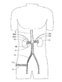
腎臓交感神経活性は、血圧の上昇を開始し、持続させると考えられている。慢性的な血圧上昇、または高血圧は、心臓疾患および死亡の大きな原因であり、世界中で数100万人を苦しめている。一般に慢性血圧が収縮期に140mmHgを超え、拡張期に90mmHgを超える人は、高血圧に罹患していると分類される。腎除神経が血圧を低下させることが、見出された。腎神経は、腎動脈を包囲しており、腎動脈は、大腿動脈から即座にアクセス可能である。腎神経を標的とすることが、降圧を超える更に有利な結果を提供し、メタボリックシンドローム、心不全、睡眠時無呼吸症候群、腎不全および糖尿病性腎症などの手順のために主要な動機づけとなり得る。 Renal sympathetic nerve activity is thought to initiate and sustain an increase in blood pressure. Chronic blood pressure rise, or high blood pressure, is a major cause of heart disease and death, afflicting millions of people worldwide. In general, a person whose chronic blood pressure exceeds 140 mmHg during systole and exceeds 90 mmHg during diastole is classified as suffering from hypertension. It has been found that renal denervation reduces blood pressure. The renal nerve surrounds the renal artery, which is immediately accessible from the femoral artery. Targeting the renal nerve provides more favorable results over hypotension and can be a major motivation for procedures such as metabolic syndrome, heart failure, sleep apnea syndrome, renal failure and diabetic nephropathy .
本開示の態様において、可撓性マイクロ波カテーテルが、提供される。開示の可撓性マイクロ波カテーテルは、内部導体と、内部導体の周りに同軸上に配設された内部誘電絶縁体と、内部誘電体の周りに同軸上に配設された外部導体と、を有する可撓性同軸ケーブルを含む。開示の可撓性マイクロ波カテーテルは、可撓性同軸ケーブルのマイクロ波放射部分を画定する少なくとも1つの給電点を含む。折畳み構成および拡張構成を有し、可撓性同軸ケーブルのマイクロ波放射部分の周りに配設されたメッシュ構造が提供され、メッシュ構造は、可撓性マイクロ波カテーテルから半径方向に外方へ拡張しており、それによりメッシュ構造の半径方向中心に少なくとも1つの給電点を配置させる。一部態様において、可撓性マイクロ波カテーテルのメッシュ構造は、軸方向のマイクロ波放射部分から除神経エネルギーの伝搬を低減する導電性材料を含む。 In aspects of the present disclosure, a flexible microwave catheter is provided. The disclosed flexible microwave catheter includes an inner conductor, an inner dielectric insulator disposed coaxially around the inner conductor, and an outer conductor disposed coaxially around the inner dielectric. A flexible coaxial cable. The disclosed flexible microwave catheter includes at least one feed point that defines the microwave radiating portion of the flexible coaxial cable. A mesh structure is provided that has a folded configuration and an expanded configuration and is disposed around the microwave radiating portion of the flexible coaxial cable, the mesh structure extending radially outward from the flexible microwave catheter. Thereby, at least one feeding point is arranged at the radial center of the mesh structure. In some aspects, the mesh structure of the flexible microwave catheter includes a conductive material that reduces the denervation energy propagation from the axial microwave radiation portion.
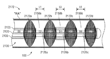
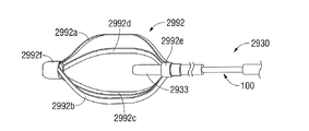
一部態様において、メッシュ構造は、その内表面上に配設された導電性パターンを有する弾性バルーンを含む。一部態様において、拡張構成における弾性バルーンは、メッシュ構造の半径方向中心に少なくとも1つの給電点を配置させる。一部態様において、導電性パターンは、弾性バルーンの内表面上の窓を画定し、その窓は、導電性パターンを有さないことを特徴とする。一部態様において、メッシュ構造および少なくとも1つの給電点は、円周方向に均衡のとれた共鳴構造を形成する。一部態様において、メッシュ構造は、先端導電性エンドキャップメッシュと、基端導電性エンドキャップメッシュと、先端エンドキャップメッシュと基端エンドキャップメッシュとの間に形成された管状メッシュ本体と、を更に含み、先端エンドキャップメッシュおよび基端エンドキャップメッシュは、軸方向のマイクロ波放射部分からマイクロ波エネルギーの伝搬を低減する。一部態様において、管状メッシュ本体は、約2cm〜約3cmの長手方向範囲に沿って360°にわたりエネルギーを放射する窓を画定する。 In some aspects, the mesh structure includes an elastic balloon having a conductive pattern disposed on its inner surface. In some aspects, the elastic balloon in the expanded configuration places at least one feed point at the radial center of the mesh structure. In some aspects, the conductive pattern defines a window on the inner surface of the elastic balloon, the window having no conductive pattern. In some aspects, the mesh structure and the at least one feed point form a resonant structure that is balanced in the circumferential direction. In some aspects, the mesh structure further comprises a distal conductive end cap mesh, a proximal conductive end cap mesh, and a tubular mesh body formed between the distal end cap mesh and the proximal end cap mesh. Including, the distal end cap mesh and the proximal end cap mesh reduce propagation of microwave energy from the axial microwave radiation portion. In some aspects, the tubular mesh body defines a window that emits energy over 360 degrees along a longitudinal extent of about 2 cm to about 3 cm.
本開示の別の態様において、内部導体と、内部導体の周りに同軸上に配設された内部誘電体と、内部誘電体の周りに同軸上に配設された外部導体と、を有する可撓性同軸ケーブルを有する可撓性マイクロ波カテーテルが、提供される。少なくとも1つの給電間隙が、可撓性同軸ケーブルのマイクロ波放射部分を画定する。センタリング構造が、可撓性同軸ケーブルのマイクロ波放射部分に隣接して配設され、それは折畳み構成および拡張構成を有し、センタリング構造は、可撓性マイクロ波カテーテルから半径方向に外方へ延在しており、それによりセンタリング構造の半径方向中心に少なくとも1つの給電点を配置させる。 In another aspect of the present disclosure, a flexible having an inner conductor, an inner dielectric disposed coaxially around the inner conductor, and an outer conductor disposed coaxially around the inner dielectric. A flexible microwave catheter having a conductive coaxial cable is provided. At least one feed gap defines a microwave radiating portion of the flexible coaxial cable. A centering structure is disposed adjacent to the microwave radiating portion of the flexible coaxial cable, which has a folded configuration and an expanded configuration, the centering structure extending radially outward from the flexible microwave catheter. At least one feed point at the radial center of the centering structure.
一部態様において、可撓性マイクロ波カテーテルのセンタリング構造は、可撓性マイクロ波カテーテルの外側のシースのコンファイド(confides)から先端に進めると管状形状に拡張するステント様拡張可能な要素を含む。一部態様において、ステント様拡張可能な要素は、長手方向の範囲に沿って360°にわたりエネルギーを放射させる複数の窓を画定する。一部態様において、センタリング構造は、複数のセンタリングデバイスと、少なくとも1つの給電間隙の各先端に配設されている複数のセンタリングデバイスの少なくとも1つと、少なくとも1つの給電間隙の各基端に配設されている複数のセンタリングデバイスの少なくとも1つと、を含む。一部態様において、複数のセンタリングデバイスは、少なくとも1つの給電間隙のそれぞれから軸方向へのマイクロ波エネルギーの伝搬を低減する。一部態様において、少なくとも1つの給電間隙は、第一の給電間隙および第二の給電間隙を含み、センタリング構造は、第一の給電間隙に動作可能に結合した第一のセンタリングデバイスと、第二の給電間隙に動作可能に結合した第二のセンタリングデバイスと、を更に含み、拡張構成において、第一の給電間隙は、第一のセンタリングデバイスの半径方向中心にあり、第二の給電間隙は、第二のセンタリングデバイスの半径方向中心にある。一部態様において、第一のセンタリングデバイスおよび第二のセンタリングデバイスは、それぞれマイクロ波エネルギーを放射する窓を画定する。 In some aspects, the centering structure of the flexible microwave catheter includes a stent-like expandable element that expands to a tubular shape upon advancement from the outer sheath confieds of the flexible microwave catheter. In some aspects, the stent-like expandable element defines a plurality of windows that radiate energy over 360 ° along the longitudinal extent. In some aspects, the centering structure is disposed at each proximal end of the plurality of centering devices, at least one of the plurality of centering devices disposed at each distal end of the at least one feeding gap, and at least one feeding gap. And at least one of a plurality of centering devices. In some aspects, the plurality of centering devices reduce the propagation of microwave energy in the axial direction from each of the at least one feed gap. In some aspects, the at least one feed gap includes a first feed gap and a second feed gap, and the centering structure includes a first centering device operably coupled to the first feed gap, and a second feed gap. A second centering device operably coupled to the feed gap, wherein, in the expanded configuration, the first feed gap is at a radial center of the first centering device and the second feed gap is At the radial center of the second centering device. In some aspects, the first centering device and the second centering device each define a window that emits microwave energy.
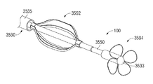
一部態様において、センタリング構造は、膨張可能なバルーンハウジングと、膨張可能なバルーンハウジング上に形成された複数の突出部と、を含み、拡張構成において、溝が、複数の突出部の隣接する突出部間に形成されている。一部態様において、センタリング構造は、可撓性マイクロ波カテーテルの円周の周りに等しい間隔で複数のフィンを含み、折畳み構成において複数のフィンが、可撓性マイクロ波カテーテルの外部シース内に抑制されており、拡張構成において複数のフィンは、可撓性マイクロ波カテーテルから半径方向に外方へ延在している。一部態様において、複数のフィンは、流体流動ルーメンを流れる流体により発生された流体/水力学的力を介して流体流動ルーメン内に可撓性マイクロ波カテーテルをセルフセンタリングするような寸法である。 In some aspects, the centering structure includes an inflatable balloon housing and a plurality of protrusions formed on the inflatable balloon housing, wherein, in the expanded configuration, the grooves are adjacent protrusions of the plurality of protrusions. It is formed between the parts. In some aspects, the centering structure includes a plurality of fins equally spaced around the circumference of the flexible microwave catheter, wherein the plurality of fins are constrained within the outer sheath of the flexible microwave catheter. In the expanded configuration, the plurality of fins extend radially outward from the flexible microwave catheter. In some aspects, the plurality of fins are sized to self-center the flexible microwave catheter into the fluid flow lumen via fluid / hydraulic forces generated by the fluid flowing through the fluid flow lumen.
一部態様において、センタリング構造は、センタリングバスケットを含む。センタリングバスケットは、可撓性マイクロ波カテーテルを係合するための第一のレシーバーと、可撓性マイクロ波カテーテルを係合するための第二のレシーバーと、第一のレシーバーと第二のレシーバーとの間に延在する複数のバンドと、を含み、複数のバンドのそれぞれは、外方に湾曲し、第一のレシーバーと第二のレシーバーとの間に弓形の通路を形成している。折畳み構成において複数のバンドは、半径方向に内方へ圧縮されており、それによりセンタリングバスケットを延長させている。拡張構成において複数のバンドは、圧縮されずに半径方向に外方へ延在している。一部態様において、第一のレシーバーは、可撓性マイクロ波カテーテルを堅固に係合しており、第二のレシーバーは、可撓性マイクロ波カテーテルを滑動可能に係合している。 In some aspects, the centering structure includes a centering basket. The centering basket includes a first receiver for engaging the flexible microwave catheter, a second receiver for engaging the flexible microwave catheter, a first receiver and a second receiver. A plurality of bands extending between each of the plurality of bands, each of which is curved outwardly to form an arcuate path between the first receiver and the second receiver. In the folded configuration, the plurality of bands are radially compressed inward, thereby extending the centering basket. In the expanded configuration, the plurality of bands extend radially outward without being compressed. In some embodiments, the first receiver firmly engages the flexible microwave catheter and the second receiver slidably engages the flexible microwave catheter.
一部態様において、センタリング構造は、少なくとも2つのセンタリングバスケットを含む。少なくとも2つのセンタリングバスケットのそれぞれは、可撓性マイクロ波カテーテルを係合するための第一のレシーバーと、可撓性マイクロ波カテーテルを係合するための第二のレシーバーと、第一のレシーバーと第二のレシーバーとの間に延在する複数のバンドと、を含み、複数のバンドのそれぞれは、外方に湾曲し、第一のレシーバーと第二のレシーバーとの間に弓形の通路を形成している。折畳み構成において、複数のバンドは、半径方向に内方へ圧縮されており、それによりセンタリングバスケットを延長させており、拡張構成において、複数のバンドは、圧縮されずに半径方向に外方へ延在している。一部態様において、第一のレシーバーは、可撓性マイクロ波カテーテルを堅固に係合しており、第二のレシーバーは、可撓性マイクロ波カテーテルを滑動可能に係合している。一部態様において、少なくとも1つの給電間隙の1つは、少なくとも2つのセンタリングバスケットの一番目と二番目との間に置かれている。 In some aspects, the centering structure includes at least two centering baskets. Each of the at least two centering baskets includes a first receiver for engaging a flexible microwave catheter, a second receiver for engaging a flexible microwave catheter, and a first receiver A plurality of bands extending between the second receiver and each of the plurality of bands is curved outwardly to form an arcuate path between the first receiver and the second receiver doing. In the folded configuration, the bands are compressed radially inward, thereby extending the centering basket, and in the expanded configuration, the bands extend radially outward without being compressed. Exist. In some embodiments, the first receiver firmly engages the flexible microwave catheter and the second receiver slidably engages the flexible microwave catheter. In some aspects, one of the at least one feed gap is located between the first and second of the at least two centering baskets.
一部態様において、センタリング構造は、可撓性マイクロ波カテーテルの円周の周りに等しいな間隔で複数のパドルを含む。複数のパドルのそれぞれは、可撓性マイクロ波カテーテルにヒンジ結合されており、折畳み構成において複数のパドルは、隣接しており可撓性マイクロ波カテーテルに平行であり、拡張構成において複数のパドルは、可撓性マイクロ波カテーテルに垂直に延在し、そこから半径方向に外方へ延在している。 In some aspects, the centering structure includes a plurality of paddles spaced equally around the circumference of the flexible microwave catheter. Each of the plurality of paddles is hinged to the flexible microwave catheter, wherein the plurality of paddles are adjacent and parallel to the flexible microwave catheter in the folded configuration, and the plurality of paddles are in the expanded configuration. , Extending perpendicular to the flexible microwave catheter and extending radially outward therefrom.
一部態様において、センタリング構造は、可撓性マイクロ波カテーテルの外表面に連結されており、螺旋様の方式で可撓性マイクロ波カテーテルの外表面の周りに延在する、複数の螺旋状リブを含み、折畳み構成では複数の螺旋状リブは、可撓性ケーブルと可撓性マイクロ波カテーテルの外部シースの内表面との間に圧縮されており、拡張構成では複数の螺旋状リブは、可撓性同軸ケーブルから半径方向に延在している。 In some aspects, the centering structure is coupled to the outer surface of the flexible microwave catheter and extends in a spiral-like manner around the outer surface of the flexible microwave catheter. In the folded configuration, the plurality of helical ribs are compressed between the flexible cable and the inner surface of the outer sheath of the flexible microwave catheter, and in the expanded configuration, the plurality of helical ribs are acceptable. Extending radially from the flexible coaxial cable.
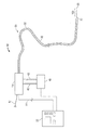
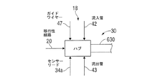
本開示の更に別の態様において、同軸可撓性ケーブルに連結するカップラーと、流体冷却システムと、カテーテルの外部シースと、が提供される。カップラーは、流体カップラー本体内に形成されており、冷却流体の供給源に動作可能に結合してそれから流体を受け取るように構成された流体入口と、流体カップラー本体内に形成されており、流体排出部に動作可能に連結するように構成された流体出口と、同軸ケーブルと滑動可能に連結するための開口を形成するバイパスバルブと、液密性シールを形成しながらカテーテルの外部シースと連結するための開口を形成する外部シースカップラーと、を有する流体カップラー本体を含む。該カップラーは、流入ルーメンの外表面の周りの液密性シールと流体カップラー本体の内表面との液密性シールを形成して、流体出口と流体連通する流出プレナムを画定するように構成された、先端密閉ダイヤフラムを有する流体カップラー本体内に収容された流体密閉システムを含み、流出プレナムは、流体カップラー本体の先端内表面と、流入ルーメンの外表面と、先端密閉ダイヤフラムの先端側と、外部シースカップラーと、の間に形成されている。該カップラーは、同軸ケーブルの外表面の周りの液密性シールと、流体カップラー本体の内表面との液密性シールとを形成し、それにより流体入口と流体連通する流入プレナムを形成するように構成された、基端密閉ダイヤフラムを含み、流出プレナムは、流体カップラー本体の基端内表面と、先端密閉ダイヤフラムの基端側と、基端密閉ダイヤフラムの基端側と、の間に形成されている。 In yet another aspect of the present disclosure, a coupler coupled to a coaxial flexible cable, a fluid cooling system, and an outer sheath of a catheter are provided. The coupler is formed in the fluid coupler body, and is formed in the fluid coupler body and fluid inlet configured to operably couple to and receive fluid therefrom. A fluid outlet configured to be operably coupled to the body; a bypass valve that forms an opening for slidably coupling with the coaxial cable; and a fluid-tight seal for coupling to the outer sheath of the catheter And a fluid coupler body having an outer sheath coupler that forms an opening. The coupler is configured to form a liquid tight seal around the outer surface of the inlet lumen and a liquid tight seal between the inner surface of the fluid coupler body and define an outlet plenum in fluid communication with the fluid outlet. Including a fluid sealing system housed within a fluid coupler body having a tip sealing diaphragm, wherein the outflow plenum includes a tip inner surface of the fluid coupler body, an outer surface of the inlet lumen, a tip side of the tip sealing diaphragm, and an outer sheath. And the coupler. The coupler forms a liquid tight seal around the outer surface of the coaxial cable and a liquid tight seal with the inner surface of the fluid coupler body, thereby forming an inflow plenum in fluid communication with the fluid inlet. And a spill plenum is formed between the proximal inner surface of the fluid coupler body, the proximal side of the distal sealing diaphragm, and the proximal side of the proximal sealing diaphragm. Yes.
一部態様において、カテーテルは、内部ルーメンの周りに同軸上に形成されており、内部ルーメンは、同軸ケーブルの周りに同軸上に形成されており、流入プレナムは、同軸ケーブルの外表面と流入ルーメンの内表面との間に形成された流体通路と流体連通している。一部態様において、カテーテルは、内部ルーメンの周りに同軸上に形成されており、内部ルーメンは、同軸ケーブルの周りに同軸上に形成されており、流出プレナムは、流入ルーメンの外表面と外部シースの内表面との間に形成された流体通路と流動連通している。 In some embodiments, the catheter is formed coaxially about the inner lumen, the inner lumen is formed coaxially about the coaxial cable, and the inflow plenum is formed between the outer surface of the coaxial cable and the inflow lumen. In fluid communication with a fluid passage formed therebetween. In some aspects, the catheter is formed coaxially about the inner lumen, the inner lumen is formed coaxially about the coaxial cable, and the outflow plenum includes the outer surface of the inflow lumen and the outer sheath. In fluid communication with a fluid passage formed therebetween.
一部態様において、カテーテルは、内部ルーメンの周りに同軸上に形成されており、内部ルーメンは、同軸ケーブルの周りに同軸上に形成されており、流入プレナムは、同軸ケーブルの外表面と流入ルーメンの内表面との間に形成された流体通路と流体連通しており、流出プレナムは、流入ルーメンの外表面と外部シースの内表面との間に形成された流体通路と流動連通している。一部態様において、流体カップラー本体は、同軸ケーブルを滑動可能に係合している。 In some embodiments, the catheter is formed coaxially about the inner lumen, the inner lumen is formed coaxially about the coaxial cable, and the inflow plenum is formed between the outer surface of the coaxial cable and the inflow lumen. The outflow plenum is in fluid communication with a fluid passage formed between the outer surface of the inflow lumen and the inner surface of the outer sheath. In some aspects, the fluid coupler body slidably engages the coaxial cable.
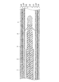
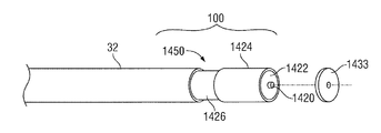
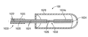
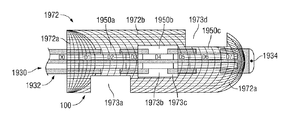
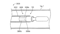
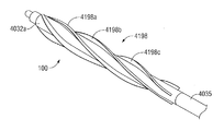
本開示の更に別の態様において、マイクロ波エネルギー送達デバイスが、提供される。マイクロ波エネルギー送達デバイスは、内部導体と、内部導体の周りに同軸上に配設された内部誘電絶縁体と、内部誘電体の周りに同軸上に配設された外部導体と、を有する同軸給電路を含む。マイクロ波エネルギー送達デバイスは、同軸給電路の先端に動作可能に連結された放射部分を含む。放射部分は、同軸給電路の内部導体の先端に動作可能に連結されておりそこから伸長する放射部分の内部導体と、放射部分の内部導体の周りを螺旋状に包囲し、同軸給電路の外部導体に動作可能に連結された遮蔽外部導体と、放射部分の内部導体と遮蔽外部導体との間に配置された遮蔽誘電体と、を含む。遮蔽外部導体の幅は、同軸給電路の内部導体に沿った長手方向位置に応じて変動する。キャップが、放射部分の内部導体および遮蔽外部導体の先端に動作可能に連結し、それらを電気的に結合させる。 In yet another aspect of the present disclosure, a microwave energy delivery device is provided. A microwave energy delivery device includes an inner conductor, an inner dielectric insulator disposed coaxially around the inner conductor, and an outer conductor disposed coaxially around the inner dielectric. Including roads. The microwave energy delivery device includes a radiating portion operably coupled to the tip of the coaxial feed path. The radiating portion is operatively connected to the tip of the inner conductor of the coaxial feeding path, and extends radially from the inner conductor of the radiating portion, and surrounds the inner conductor of the radiating portion in a spiral shape, and the outside of the coaxial feeding path A shielding outer conductor operatively coupled to the conductor, and a shielding dielectric disposed between the inner conductor and the shielding outer conductor of the radiating portion. The width of the shielding outer conductor varies according to the position in the longitudinal direction along the inner conductor of the coaxial feed path. A cap is operably connected to and electrically coupled to the tips of the inner and shield outer conductors of the radiating portion.
一部態様において、マイクロ波エネルギー送達デバイスは、先端に配設された温度センサーを含む。一部態様において、放射部分により発生した放射パターンは、遮蔽外部導体の可変性の幅、または遮蔽外部導体の可変性の螺旋角度のうちの少なくとも一方に関係する。 In some embodiments, the microwave energy delivery device includes a temperature sensor disposed at the tip. In some aspects, the radiation pattern generated by the radiating portion is related to at least one of a variable width of the shielded outer conductor or a variable spiral angle of the shielded outer conductor.
一部態様において、マイクロ波エネルギー送達デバイスは、遮蔽外部導体の隣接するラップ間に形成された空隙により画定される給電間隙を含む。一部態様において、断面に沿った給電間隙の円周と遮蔽外部導体の円周との比により定義される給電間隙比は、遮蔽外部導体の基端から遮蔽外部導体の先端まで直線的に変化する。一部態様において、給電間隙比は、遮蔽外部導体の基端から遮蔽外部導体の先端まで非直線的に変化する。一部態様において、給電間隙比は、放射部分の基端における0%から放射部分の先端における約50%まで変動する。一部態様において、給電間隙比は、放射部分の基端における0%から放射部分の先端における約100%まで変動する。 In some aspects, the microwave energy delivery device includes a feed gap defined by a gap formed between adjacent wraps of the shielded outer conductor. In some aspects, the feed gap ratio defined by the ratio of the circumference of the feed gap along the cross section to the circumference of the shield outer conductor varies linearly from the proximal end of the shield outer conductor to the tip of the shield outer conductor. To do. In some aspects, the feed gap ratio varies non-linearly from the proximal end of the shielding outer conductor to the distal end of the shielding outer conductor. In some aspects, the feed gap ratio varies from 0% at the proximal end of the radiating portion to about 50% at the distal end of the radiating portion. In some aspects, the feed gap ratio varies from 0% at the proximal end of the radiating portion to about 100% at the distal end of the radiating portion.
一部態様において、マイクロ波エネルギー送達デバイスは、放射部分の長手方向の長さに沿って延在する螺旋形の電磁場を発生する。一部態様において、螺旋形の電磁場は、遮蔽外部導体の個々のラップ間に形成された空隙に関係する。一部態様において、遮蔽外部導体は、少なくとも2つの螺旋回転を含む。一部態様において、キャップは、放射部分の内部導体と遮蔽外部導体との間を電気的に結合させる。 In some embodiments, the microwave energy delivery device generates a helical electromagnetic field that extends along the longitudinal length of the radiating portion. In some aspects, the helical electromagnetic field is related to air gaps formed between individual wraps of the shielded outer conductor. In some aspects, the shielding outer conductor includes at least two helical rotations. In some embodiments, the cap electrically couples between the radiating portion inner conductor and the shielding outer conductor.
本開示の更に別の態様において、内部導体と、内部導体の周りに同軸上に配設された内部誘電絶縁体と、内部誘電体の周りに同軸上に配設された外部導体と、を有する同軸給電路を含むマイクロ波エネルギー送達デバイスが、提供される。マイクロ波エネルギー送達デバイスは、同軸給電路の内部導体の先端に動作可能に連結され、そこから伸長する放射部分の内部導体と、放射部分の内部導体の周りを螺旋状に包囲し、同軸給電路の外部導体に動作可能に連結された遮蔽外部導体と、放射部分の内部導体と遮蔽外部導体との間に配置された遮蔽誘電体と、を含む、同軸給電路の先端に動作可能に連結された放射部分を含む。遮蔽外部導体の螺旋角度は、同軸給電路の内部導体に沿って、その長手方向位置により変動する。キャップが、放射部分の内部導体および遮蔽外部導体のうちの少なくとも一方の先端に動作可能に連結している。 In yet another aspect of the present disclosure, an inner conductor, an inner dielectric insulator disposed coaxially around the inner conductor, and an outer conductor disposed coaxially around the inner dielectric. A microwave energy delivery device including a coaxial feed path is provided. The microwave energy delivery device is operably connected to the tip of the inner conductor of the coaxial feed line, and spirally surrounds the inner conductor of the radiating portion extending from the inner conductor of the radiating portion, Operatively connected to the end of the coaxial feedway, including a shielded outer conductor operably coupled to the outer conductor of the shield and a shielding dielectric disposed between the inner conductor and the shielded outer conductor of the radiating portion. Including radiating parts. The spiral angle of the shield outer conductor varies with the position in the longitudinal direction along the inner conductor of the coaxial feeding path. A cap is operatively connected to the tip of at least one of the inner conductor and the shield outer conductor of the radiating portion.
一部態様において、マイクロ波エネルギー送達デバイスは、遮蔽外部導体の隣接するラップ間に形成された空隙により画定された給電間隙を含む。一部態様において、断面に沿った給電間隙の円周と遮蔽外部導体の円周の比により定義される給電間隙比は、遮蔽外部導体の基端から遮蔽外部導体の先端まで直線的に変化する。一部態様において、給電間隙比は、遮蔽外部導体の基端から遮蔽外部導体の先端まで非直線的に変化する。一部態様において、給電間隙比は、放射部分の基端における0%から放射部分の先端における約50%まで変動する。一部態様において、マイクロ波エネルギー送達デバイスは、放射部分の長手方向の長さに沿って延在する螺旋形の電磁場を発生する。一部態様において、螺旋形の電磁場は、遮蔽外部導体の個々のラップ間に形成された空隙に関係する。一部態様において、キャップが、放射部分の内部導体と遮蔽外部導体との間を電気的に結合させる。 In some aspects, the microwave energy delivery device includes a feed gap defined by a gap formed between adjacent wraps of the shielded outer conductor. In some aspects, the feed gap ratio defined by the ratio of the circumference of the feed gap along the cross section to the circumference of the shield outer conductor varies linearly from the proximal end of the shield outer conductor to the tip of the shield outer conductor. . In some aspects, the feed gap ratio varies non-linearly from the proximal end of the shielding outer conductor to the distal end of the shielding outer conductor. In some aspects, the feed gap ratio varies from 0% at the proximal end of the radiating portion to about 50% at the distal end of the radiating portion. In some embodiments, the microwave energy delivery device generates a helical electromagnetic field that extends along the longitudinal length of the radiating portion. In some aspects, the helical electromagnetic field is related to air gaps formed between individual wraps of the shielded outer conductor. In some embodiments, the cap electrically couples between the radiating portion inner conductor and the shielding outer conductor.
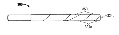
本開示の更に別の態様において、内部導体と、内部導体の周りに同軸上に配設された内部誘電絶縁体と、内部誘電体の周りに同軸上に配設された外部導体と、を有する同軸給電路を含むマイクロ波エネルギー送達デバイスが、提供される。開示のマイクロ波エネルギー送達デバイスは、同軸給電路の先端に動作可能に連結された放射部分を含む。放射部分は、同軸給電路の内部導体の先端に動作可能に連結され、そこから伸長する放射部分の内部導体と、放射部分の内部導体の周りを螺旋状に包囲し、同軸給電路の外部導体に動作可能に連結された遮蔽外部導体と、放射部分の内部導体と遮蔽外部導体との間に配置された遮蔽誘電体と、を含む。遮蔽外部導体の螺旋角度のピッチは、同軸給電路の内部導体に沿って、その長手方向位置により変動する。キャップが、放射部分の内部導体および遮蔽外部導体のうちの少なくとも一方の先端に動作可能に連結している。 In yet another aspect of the present disclosure, an inner conductor, an inner dielectric insulator disposed coaxially around the inner conductor, and an outer conductor disposed coaxially around the inner dielectric. A microwave energy delivery device including a coaxial feed path is provided. The disclosed microwave energy delivery device includes a radiating portion operably coupled to the tip of a coaxial feed path. The radiating portion is operatively connected to the tip of the inner conductor of the coaxial feed line, and surrounds the inner conductor of the radiating portion extending from the spiral, and the outer conductor of the coaxial feed path spirally surrounding the inner conductor of the radiating portion. A shield outer conductor operatively coupled to the shield and a shield dielectric disposed between the inner conductor and the shield outer conductor of the radiating portion. The pitch of the helix angle of the shielding outer conductor varies with the position in the longitudinal direction along the inner conductor of the coaxial feeding path. A cap is operatively connected to the tip of at least one of the inner conductor and the shield outer conductor of the radiating portion.
一部態様において、マイクロ波エネルギー送達デバイスは、遮蔽外部導体の隣接するラップ間に形成された空隙により画定された給電間隙を含む。一部態様において、断面に沿った給電間隙の円周と遮蔽外部導体の円周の比により定義される給電間隙比は、遮蔽外部導体の基端から遮蔽外部導体の先端まで直線的に変化する。一部態様において、給電間隙比は、遮蔽外部導体の基端から遮蔽外部導体の先端まで非直線的に変化する。一部態様において、給電間隙比は、放射部分の基端における0%から放射部分の先端における約50%まで変動する。一部態様において、マイクロ波エネルギー送達デバイスは、放射部分の長手方向の長さに沿って延在する螺旋形の電磁場を発生する。一部態様において、螺旋形の電磁場は、遮蔽外部導体の個々のラップ間に形成された空隙に関係する。一部態様において、キャップは、放射部分の内部導体と遮蔽外部導体との間を電気的に結合させる。 In some aspects, the microwave energy delivery device includes a feed gap defined by a gap formed between adjacent wraps of the shielded outer conductor. In some aspects, the feed gap ratio defined by the ratio of the circumference of the feed gap along the cross section to the circumference of the shield outer conductor varies linearly from the proximal end of the shield outer conductor to the tip of the shield outer conductor. . In some aspects, the feed gap ratio varies non-linearly from the proximal end of the shielding outer conductor to the distal end of the shielding outer conductor. In some aspects, the feed gap ratio varies from 0% at the proximal end of the radiating portion to about 50% at the distal end of the radiating portion. In some embodiments, the microwave energy delivery device generates a helical electromagnetic field that extends along the longitudinal length of the radiating portion. In some aspects, the helical electromagnetic field is related to air gaps formed between individual wraps of the shielded outer conductor. In some embodiments, the cap electrically couples between the radiating portion inner conductor and the shielding outer conductor.
本開示の更に別の態様において、体腔内に共鳴構造を形成する方法が、提供される。該方法は、可撓性マイクロ波カテーテルを患者の体腔により前進させることを含み、可撓性マイクロ波カテーテルは、可撓性マイクロ波カテーテルの先端に放射部分を含み、放射部分が、マイクロ波周波数のマイクロ波エネルギー信号を受信するように構成されており、少なくとも1つのセンタリングデバイスが、放射部分に隣接し、可撓性マイクロ波カテーテルから半径方向に外方へ展開するように構成されている。放射部分は、標的組織に隣接して配置される。少なくとも1つのセンタリングデバイスは、体腔内で可撓性マイクロ波カテーテルから半径方向に外方へ展開されて、体腔の半径方向中心で放射部分を配置させる。円周方向に均衡のとれた共鳴構造が、放射部分を介して体腔内に形成され、マイクロ波周波数でのマイクロなエネルギー信号が、放射部分から送達されて、マイクロ波周波数で体腔を共鳴させる。 In yet another aspect of the present disclosure, a method for forming a resonant structure in a body cavity is provided. The method includes advancing a flexible microwave catheter through a body cavity of a patient, the flexible microwave catheter including a radiating portion at the distal end of the flexible microwave catheter, the radiating portion being at a microwave frequency. And at least one centering device is configured to deploy radially outward from the flexible microwave catheter adjacent to the radiating portion. The radiating portion is positioned adjacent to the target tissue. At least one centering device is deployed radially outward from the flexible microwave catheter within the body cavity to place the radiating portion at the radial center of the body cavity. A circumferentially balanced resonant structure is formed in the body cavity through the radiating portion, and a micro energy signal at the microwave frequency is delivered from the radiating portion to resonate the body cavity at the microwave frequency.
一部態様において、円周方向に均衡のとれた共鳴構造は、約2cm〜約3cmの長手方向範囲に沿って360°にわたりエネルギーを放射する。一部態様において、体腔は、腎動脈である。一部態様において、標的組織は、腎神経であり、円周方向に均衡のとれた共鳴構造は、標的組織を除神経する電磁場を発生する。 In some aspects, the circumferentially balanced resonant structure radiates energy over 360 degrees along a longitudinal range of about 2 cm to about 3 cm. In some embodiments, the body cavity is a renal artery. In some embodiments, the target tissue is a renal nerve and the circumferentially balanced resonant structure generates an electromagnetic field that denerves the target tissue.
一部態様において、該方法は、体腔による連続流体流動を提供するステップ、および体腔の少なくとも一部を冷却するステップを含む。一部態様において、該方法は、体腔の重大な構造を防御しながら、十分量のエネルギーを送達して標的組織を効果的に損傷させるまで、マイクロ波エネルギー信号の送達を継続するステップを更に含む。 In some aspects, the method includes providing continuous fluid flow through the body cavity and cooling at least a portion of the body cavity. In some aspects, the method further comprises continuing the delivery of the microwave energy signal until a sufficient amount of energy is delivered to effectively damage the target tissue while protecting critical structures of the body cavity. .
一部態様において、該方法は、連続流体流動の温度をモニタリングするステップ、およびモニタリングされた温度が閾値温度を超えていればマイクロ波エネルギーの送達を停止するステップ、を更に含む。 In some embodiments, the method further includes monitoring the temperature of the continuous fluid flow and stopping the delivery of microwave energy if the monitored temperature exceeds a threshold temperature.
一部態様において、体腔は、胃腸管腔、耳管腔、呼吸器系管腔、泌尿器系管腔、女性生殖器系管腔、男性生殖器系管腔、血管系管腔、および内臓のうちの少なくとも1つから選択される。 In some embodiments, the body cavity is at least one of a gastrointestinal lumen, an ear lumen, a respiratory lumen, a urinary lumen, a female genital lumen, a male genital lumen, a vascular lumen, and a viscera One is selected.
一部態様において、該方法は、体腔を拡張してマイクロ波周波数に関係する構造を形成することを更に含む。 In some embodiments, the method further includes dilating the body cavity to form a structure related to the microwave frequency.
一部態様において、該方法は、マイクロ波周波数を選択して、体腔の解剖学的構造に基づき体腔を共鳴させることを更に含む。 In some embodiments, the method further includes selecting a microwave frequency to resonate the body cavity based on the anatomy of the body cavity.
一部態様において、該方法は、体腔内の温度をモニタリングすることと、その温度が閾値温度を超えていればマイクロ波エネルギー信号の送達を停止することと、を更に含む。 In some embodiments, the method further includes monitoring the temperature in the body cavity and stopping delivery of the microwave energy signal if the temperature exceeds a threshold temperature.
一部態様において、放射部分は、可撓性マイクロ波カテーテル内の開回路を形成する給電間隙を含む。一部態様において、放射部分は、第一の給電間隙および第二の給電間隙を含み、第一および第二の給電間隙は、それぞれ可撓性マイクロ波カテーテル内に開回路を形成する。 In some aspects, the radiating portion includes a feed gap that forms an open circuit within the flexible microwave catheter. In some embodiments, the radiating portion includes a first feed gap and a second feed gap, the first and second feed gaps each forming an open circuit within the flexible microwave catheter.
本開示の更に別の態様において、体腔内に共鳴構造を形成させる方法が、提示される。提示された方法は、可撓性マイクロ波カテーテルを患者の体腔により前進させることを含む。可撓性マイクロ波カテーテルは、マイクロ波周波数のマイクロ波エネルギー信号を受信するように構成された可撓性マイクロ波カテーテルの先端の放射部分と、放射部分に隣接する電気伝導性メッシュと、放射部分の周りで電気伝導性メッシュを展開するように構成された後退可能なシースと、を含む。該方法は、標的組織に隣接する放射部分を配置させることと、後退可能なシースを後退させることと、電気伝導性メッシュを体腔内で可撓性マイクロ波カテーテルから半径方向に外方へ展開させ、それにより体腔の半径方向中心で放射部分をセンタリングすることと、放射部分を介して体腔内に円周方向にバランスのとれた共鳴構造を形成させることと、マイクロ波周波数のマイクロ波エネルギー信号を送達して体腔をマイクロ波周波数で共鳴させることと、を含む。 In yet another aspect of the present disclosure, a method for forming a resonant structure in a body cavity is presented. The presented method involves advancing a flexible microwave catheter through a patient's body cavity. A flexible microwave catheter includes a radiating portion at the tip of a flexible microwave catheter configured to receive a microwave energy signal at a microwave frequency, an electrically conductive mesh adjacent to the radiating portion, and a radiating portion. And a retractable sheath configured to deploy an electrically conductive mesh around. The method includes placing a radiating portion adjacent to a target tissue, retracting a retractable sheath, and deploying an electrically conductive mesh radially outward from a flexible microwave catheter within a body cavity. Thereby centering the radiating part at the radial center of the body cavity, forming a circumferentially balanced resonant structure in the body cavity via the radiating part, and generating microwave energy signals at microwave frequencies. Delivering to resonate the body cavity at microwave frequencies.
一部態様において、該方法は、電気的結合性メッシュ内に、材料を有さないことを特徴とする窓を形成させることと、窓に関係して体腔の領域を加熱することと、を含む。一部態様において、体腔は、腎動脈であり、標的組織は、腎神経であり、窓に関係して体腔の領域を加熱することは、腎臓を少なくとも部分的に除神経する。 In some aspects, the method includes forming a window characterized by having no material in the electrically coupled mesh and heating a region of the body cavity relative to the window. . In some embodiments, the body cavity is a renal artery, the target tissue is a renal nerve, and heating the region of the body cavity relative to the window at least partially denervates the kidney.
一部態様において、該方法は、腎動脈の少なくとも一部を冷却するステップを含む。 In some aspects, the method includes cooling at least a portion of the renal artery.
一部態様において、該方法は、流体冷却構造を提供してエネルギー送達を促進し、可撓性マイクロ波カテーテルの少なくとも一部の加熱を低減するステップを含む。体腔は、胃腸管腔、耳管腔、呼吸器系管腔、泌尿器系管腔、女性生殖器系管腔、男性生殖器系管腔、血管系管腔、および内臓のうちの少なくとも1つから選択されてもよい。一部態様において、円周方向に均衡のとれた共鳴構造は、約2cm〜約3cmの長手方向範囲に沿って360°にわたりエネルギーを放射する。 In some aspects, the method includes providing a fluid cooling structure to facilitate energy delivery and reduce heating of at least a portion of the flexible microwave catheter. The body cavity is selected from at least one of a gastrointestinal lumen, an ear lumen, a respiratory lumen, a urinary lumen, a female genital lumen, a male genital lumen, a vascular lumen, and a viscera May be. In some aspects, the circumferentially balanced resonant structure radiates energy over 360 degrees along a longitudinal range of about 2 cm to about 3 cm.
本開示の更に別の態様において、マイクロ波アブレーション導波路を実行する方法が、提供される。該方法は、流体を運搬するように適合されており生きた生体組織から形成された管腔を選択するステップ、管腔内に長尺状内部導体を長手方向に導入するステップ、該当する解剖学的形状に隣接した管腔内の位置に長尺状内部導体の先端を配置させるステップ、管腔の長手方向軸に沿って長尺状内部導体の少なくとも一部をセンタリングするステップ、マイクロ波アブレーションエネルギーにより長尺状内部導体を励磁するステップ、および管腔で長尺状内部導体を電気的に遮断して、該当する解剖学的形状の付近のマイクロ波アブレーションエネルギーの伝搬を低減するステップ、を含む。一部態様において、管腔は、運搬される流体の誘電性により選択される。 In yet another aspect of the present disclosure, a method for performing a microwave ablation waveguide is provided. The method includes the steps of selecting a lumen formed from living biological tissue adapted to carry fluid, introducing an elongate inner conductor longitudinally into the lumen, and applicable anatomy Positioning the tip of the elongated inner conductor at a location in the lumen adjacent to the desired shape, centering at least a portion of the elongated inner conductor along the longitudinal axis of the lumen, microwave ablation energy Exciting the elongate inner conductor by means of, and electrically blocking the elongate inner conductor in the lumen to reduce the propagation of microwave ablation energy in the vicinity of the relevant anatomical shape . In some embodiments, the lumen is selected according to the dielectric properties of the fluid being carried.
一部態様において、センタリングステップは、運搬された流体の流動を容易にするセンタリング部材を提供することを含む。一部態様において、該方法は、運搬された流体の誘電性を変化させるステップを更に含む。一部態様において、該方法は、流体補正物質(fluid mendment)を運搬された流体中に導入するステップを更に含む。一部態様において、流体補正物質は、感知された電気的パラメータに応答して運搬された流体に導入される。感知された電気的パラメータは、VSWR、出力係数、インピーダンス、静電容量、インダクタンス、および抵抗からなる群より選択されてもよい。一部態様において、流体補正物質は、感知された生物学的パラメータに応答して運搬された流体に導入される。感知された生物学的パラメータは、組織温度、血圧、心拍数、呼吸数、組織インピーダンス、血中酸素度、および神経応答からなる群より選択されてもよい。一部態様において、流体補正物質は、持続的速度で運搬された流体に導入されてもよい。一部態様において、流体補正物質は、可変性の速度で運搬された流体に導入されてもよい。流体補正物質は、感知された電気的パラメータおよび/または感知された生物学的パラメータに応答して選択された速度で運搬された流体に導入されてもよい。 In some aspects, the centering step includes providing a centering member that facilitates flow of the conveyed fluid. In some aspects, the method further comprises changing the dielectric properties of the conveyed fluid. In some aspects, the method further comprises introducing a fluid compensation material into the conveyed fluid. In some aspects, the fluid correction material is introduced into the conveyed fluid in response to the sensed electrical parameter. The sensed electrical parameter may be selected from the group consisting of VSWR, power factor, impedance, capacitance, inductance, and resistance. In some embodiments, the fluid correction material is introduced into the delivered fluid in response to the sensed biological parameter. The sensed biological parameter may be selected from the group consisting of tissue temperature, blood pressure, heart rate, respiratory rate, tissue impedance, blood oxygen level, and neural response. In some aspects, the fluid correction material may be introduced into the fluid delivered at a sustained rate. In some aspects, the fluid correction material may be introduced into the fluid delivered at a variable rate. The fluid correction material may be introduced into the fluid delivered at a selected rate in response to the sensed electrical parameter and / or the sensed biological parameter.
本開示の更に別の態様において、放射パターンを有するマイクロ波アブレーション機器を用いる方法が、提供される。該方法は、流体を運搬するように適合されており生きた生体組織から形成された管腔を選択することと、管腔内にマイクロ波アブレーションパターンを導入することと、該当する解剖学的形状に隣接する位置にマイクロ波アブレーション機器の放射パターンを配置させることと、マイクロ波アブレーションエネルギーによりマイクロ波アブレーション機器を励磁することと、管腔でマイクロ波アブレーション機器を電気的に遮断して、該当する解剖学的形状の付近で管腔に沿ってマイクロ波アブレーションエネルギーの伝搬を低減することと、を含む。 In yet another aspect of the present disclosure, a method of using a microwave ablation device having a radiation pattern is provided. The method includes selecting a lumen formed from living biological tissue that is adapted to carry a fluid, introducing a microwave ablation pattern into the lumen, and a corresponding anatomical shape Place the radiation pattern of the microwave ablation device adjacent to the position, excite the microwave ablation device with microwave ablation energy, and electrically shut off the microwave ablation device in the lumen Reducing propagation of microwave ablation energy along the lumen in the vicinity of the anatomical shape.
該方法の一部態様において、管腔は、運搬される流体の誘電性に従って選択される。一部態様において、該方法は、運搬される流体の誘電性を変化させることを含む。一部態様において、該方法は、流体補正物質を運搬される流体中に導入することを含む。一部態様において、流体補正物質は、感知された電気的パラメータに応答して運搬される流体に導入される。一部態様において、感知された電気的パラメータは、VSWR、出力係数、インピーダンス、静電容量、インダクタンスおよび抵抗からなる群より選択される。一部態様において、流体補正物質は、感知された生物学的パラメータに応答して運搬される流体に導入される。一部態様において、感知された生物学的パラメータは、組織温度、血圧、心拍数、呼吸数、組織インピーダンス、血中酸素度、および神経応答からなる群より選択される。 In some aspects of the method, the lumen is selected according to the dielectric properties of the fluid being carried. In some embodiments, the method includes changing the dielectric properties of the fluid being carried. In some aspects, the method includes introducing a fluid compensation material into the fluid being carried. In some embodiments, the fluid correction material is introduced into the fluid being conveyed in response to the sensed electrical parameter. In some aspects, the sensed electrical parameter is selected from the group consisting of VSWR, power coefficient, impedance, capacitance, inductance, and resistance. In some embodiments, the fluid correction material is introduced into the fluid being conveyed in response to the sensed biological parameter. In some embodiments, the sensed biological parameter is selected from the group consisting of tissue temperature, blood pressure, heart rate, respiration rate, tissue impedance, blood oxygen level, and neural response.
本開示の更に別の態様において、マイクロ波アブレーション導波路を実行する方法が、提供される。該方法は、流体を運搬するように適合されており生きた生体組織から形成された管腔を選択するステップ、管腔内に長尺状内部導体を長手方向に導入するステップ、管腔内に長尺状内部導体の少なくとも一部を配置させることで、長尺状内部導体の長手方向軸を、管腔の長手方向軸と実質的に平行に、長手方向軸から所望の距離の、該当する解剖学的形状の付近に配置させるステップ、長尺状内部導体に沿ってマイクロ波を伝送させることで管腔が内部導体を遮断して所定の量のマイクロ波エネルギーを該当する解剖学的形状を通して伝搬させるステップ、を含む。該方法の一部態様において、管腔は、運搬される流体の誘電性により選択される。一部態様において、該方法は、運搬される流体の誘電性を変化させることを含む。一部態様において、該方法は、流体補正物質を運搬される流体中に導入することを含む。一部態様において、流体補正物質は、感知された電気的パラメータに応答して運搬される流体に導入される。一部態様において、感知された電気的パラメータは、VSWR、出力係数、インピーダンス、静電容量、インダクタンスおよび抵抗からなる群より選択される。一部態様において、流体補正物質は、感知された生物学的パラメータに応答して運搬される流体に導入される。一部態様において、感知された生物学的パラメータは、組織温度、血圧、心拍数、呼吸数、組織インピーダンス、血中酸素度、および神経応答からなる群より選択される。 In yet another aspect of the present disclosure, a method for performing a microwave ablation waveguide is provided. The method includes the steps of selecting a lumen formed from living biological tissue adapted to carry fluid, longitudinally introducing an elongated inner conductor into the lumen, By placing at least a portion of the elongate inner conductor, the longitudinal axis of the elongate inner conductor is substantially parallel to the longitudinal axis of the lumen and at a desired distance from the longitudinal axis. Placing near the anatomical shape, transmitting microwaves along the elongated inner conductor so that the lumen blocks the inner conductor and passes a predetermined amount of microwave energy through the corresponding anatomical shape Propagating. In some aspects of the method, the lumen is selected according to the dielectric properties of the fluid being carried. In some embodiments, the method includes changing the dielectric properties of the fluid being carried. In some aspects, the method includes introducing a fluid compensation material into the fluid being carried. In some embodiments, the fluid correction material is introduced into the fluid being conveyed in response to the sensed electrical parameter. In some aspects, the sensed electrical parameter is selected from the group consisting of VSWR, power coefficient, impedance, capacitance, inductance, and resistance. In some embodiments, the fluid correction material is introduced into the fluid being conveyed in response to the sensed biological parameter. In some embodiments, the sensed biological parameter is selected from the group consisting of tissue temperature, blood pressure, heart rate, respiration rate, tissue impedance, blood oxygen level, and neural response.
本開示の更に別の態様において、マイクロ波アブレーション機器を使用する方法が、提供される。該方法は、流体を運搬するように適合されており生存する生物学的組織から形成された管腔を選択することと、所定の放射パターンを生成し得る構造の外部導体を有するマイクロ波アンテナを管腔内に導入することと、該当する解剖学的形状の付近の位置にマイクロ波アンテナを配置させることと、マイクロ波アンテナをマイクロ波エネルギーで励磁することで、マイクロ波エネルギーが所定の放射パターンでマイクロ波アンテナから発出し、管腔が伝搬させるマイクロ波エネルギーの量を制御することと、を含む。該方法の一部態様において、管腔は、運搬される流体の誘電性に従って選択される。一部態様において、該方法は、運搬される流体の誘電性を変化させることを含む。一部態様において、該方法は、流体補正物質を運搬される流体中に導入することを含む。一部態様において、流体補正物質は、感知された電気的パラメータに応答して運搬される流体に導入される。一部態様において、感知された電気的パラメータは、VSWR、出力係数、インピーダンス、静電容量、インダクタンスおよび抵抗からなる群より選択される。一部態様において、流体補正物質は、感知された生物学的パラメータに応答して運搬される流体に導入される。一部態様において、感知された生物学的パラメータは、組織温度、血圧、心拍数、呼吸数、組織インピーダンス、血中酸素度、および神経応答からなる群より選択される。 In yet another aspect of the present disclosure, a method of using a microwave ablation instrument is provided. The method comprises selecting a lumen formed from living biological tissue adapted to carry a fluid and having a microwave antenna having an outer conductor structured to generate a predetermined radiation pattern. Introducing into the lumen, placing the microwave antenna in the vicinity of the relevant anatomical shape, and exciting the microwave antenna with microwave energy, the microwave energy becomes a predetermined radiation pattern And controlling the amount of microwave energy emanating from the microwave antenna and propagating through the lumen. In some aspects of the method, the lumen is selected according to the dielectric properties of the fluid being carried. In some embodiments, the method includes changing the dielectric properties of the fluid being carried. In some aspects, the method includes introducing a fluid compensation material into the fluid being carried. In some embodiments, the fluid correction material is introduced into the fluid being conveyed in response to the sensed electrical parameter. In some aspects, the sensed electrical parameter is selected from the group consisting of VSWR, power coefficient, impedance, capacitance, inductance, and resistance. In some embodiments, the fluid correction material is introduced into the fluid being conveyed in response to the sensed biological parameter. In some embodiments, the sensed biological parameter is selected from the group consisting of tissue temperature, blood pressure, heart rate, respiration rate, tissue impedance, blood oxygen level, and neural response.
本明細書に組み入れられ、本明細書の一部を構成する添付の図面は、本開示の様々な例示的実施形態を示す。上記の一般的記載および以下に示す実施形態の詳細な説明と共に、添付の図面は、本明細書に開示されるシステム、装置および方法の原理を説明するためのものである。 The accompanying drawings, which are incorporated in and constitute a part of this specification, illustrate various exemplary embodiments of the present disclosure. Together with the above general description and detailed description of the embodiments presented below, the accompanying drawings are intended to illustrate the principles of the systems, devices, and methods disclosed herein.
本開示の特定の実施形態を、添付の図面を参照しながら以下に記載するが、開示の実施形態は、単に本開示の例であり、様々な形態で具体化することができる。不要な、または余分な詳細により本開示を妨害することのないよう、周知の、および/または反復的な機能および構造は、詳細には記載していない。それゆえ、本明細書に開示された特定の実施形態、具体的構造および機能的詳細、ならびに本明細書に開示された具体的使用を説明する目的で本明細書において用いられた用語は、限定と解釈すべきでなく、事実上任意の適切に詳述された構造において本開示を多様に使用するために、単に特許請求の範囲の原理および当業者を教示するための代表的原理と解釈すべきである。この記載および図面において、類似の参照番号は、同じ、類似の、または同等の機能を実施し得る要素を表す。 Specific embodiments of the present disclosure are described below with reference to the accompanying drawings, but the disclosed embodiments are merely examples of the present disclosure and may be embodied in various forms. Well-known and / or repetitive functions and structures have not been described in detail so as not to obscure the present disclosure with unnecessary or redundant details. Therefore, the terms used herein to describe specific embodiments, specific structures and functional details disclosed herein, and specific uses disclosed herein, are Should not be construed as merely the principles of the claims and exemplary principles for teaching those of ordinary skill in the art for making various use of the disclosure in virtually any appropriately detailed structure. Should. In this description and in the drawings, like reference numbers represent elements that can perform the same, similar, or equivalent functions.
本明細書で用いられる用語「基端」は、従来の用法と同様に、使用者に近い方の機器の端部を指し、用語「先端」は、使用者からより離れた端部を指す。本明細書で用いられる配向を参照する用語、例えば「最上部」、「底部」、「上方」、「下方」、「左」、「右」、「時」などは、図、ならびにそこに示された対応する軸および形状を参照しながら例示的目的で用いられる。本開示に係る実施形態が、限定されず任意の方向に実践し得ることは、理解されなければならない。 As used herein, the term “proximal” refers to the end of the device that is closer to the user, as in conventional usage, and the term “tip” refers to the end that is further away from the user. Terms used herein to refer to orientations, such as “top”, “bottom”, “upper”, “lower”, “left”, “right”, “hour”, etc., are shown in the figure as well as there. Used for exemplary purposes with reference to the corresponding axes and shapes made. It should be understood that embodiments according to the present disclosure can be practiced in any direction without limitation.
前述のように、可撓性マイクロ波カテーテルを用いて、天然または人工管腔を利用することにより、手順を実施することができる。本明細書に開示の特定の一手順が、血管系を用いて腎臓にアクセスする除神経手順である。マイクロ波除神経エネルギーを標的神経構造、例えば非限定的に腎動脈を取り囲む交感神経束などに適用させるようにエネルギーおよびアンテナの特性を設計する実施形態が開示されるが、そのデバイスおよび方法は、任意の他の手順で、そして任意の他の管腔、臓器または身体構造において使用されてもよい。この特定の手順は、本開示に係る一部の実施形態の一般的概念および使用を実証するために用いられているに過ぎない。例えば、本明細書に開示の可撓性マイクロ波カテーテルの実施形態を用いて、呼吸器系おける手順を実施すること、例えば上気道および肺の腫瘍を処置すること、および喘息、慢性閉塞性肺疾患(COPD)、肺気腫などを処置することができる。 As described above, the procedure can be performed by utilizing a natural or artificial lumen using a flexible microwave catheter. One particular procedure disclosed herein is a denervation procedure that uses the vasculature to access the kidney. Embodiments are disclosed in which energy and antenna characteristics are designed to apply microwave denervation energy to a target neural structure, such as, but not limited to, a sympathetic nerve bundle surrounding a renal artery, but the device and method are optional It may be used in other procedures and in any other lumen, organ or body structure. This particular procedure is only used to demonstrate the general concept and use of some embodiments according to the present disclosure. For example, using the flexible microwave catheter embodiments disclosed herein to perform procedures in the respiratory system, such as treating upper airway and lung tumors, and asthma, chronic obstructive lung Diseases (COPD), emphysema, etc. can be treated.
図1に示すように、開示の可撓性マイクロ波カテーテル30は、動脈カテーテル110により大腿動脈FAに経皮導入され、右腎動脈RRA内の右腎神経束RRNに隣接して配置される。可撓性マイクロ波カテーテル30は、各右および/または左腎神経束RRN、LRN(本明細書では以後「腎神経RN」)に除神経エネルギーを送達するために、各動脈管および関連の解剖学的構造への副次的損傷を最小限にしながら、右および/または左腎動脈RRA、LRA(本明細書では以後、「腎動脈RA」)の生理学と有利に協調する放射部分100を含む。以下の議論において、腎神経RNおよび腎動脈RAを用いて、本開示に係る実施形態を例示しているが、開示の実施形態が右腎動脈RRAまたは左腎動脈LRAのいずれかと共に用いられて、各右腎神経束RRNおよび左腎神経束LRNに除神経エネルギーを送達し得ることが、理解されなければならない。
As shown in FIG. 1, the disclosed
交感神経活性の上昇は、血圧の上昇を開始し、それを持続する。腎神経束RNは、腎動脈RAの周りに束ねられた腎交感神経(遠心性および求心性)を含む。そのため、腎動脈RAは、大腿動脈FAおよび/または腹部大動脈Aによる腎神経束RNへのアクセスを容易にする。可撓性マイクロ波カテーテル30は、マイクロ波エネルギーアプリケータの放射部分100を腎神経束RNに接近して設置する。腎動脈RA内に配置されたら、放射部分100が、腎臓を除神経する試みとして、腎動脈RA内から腎動脈RAを取り囲む各腎神経束RNに向かってエネルギーを集中させ、最終的に血圧を低下させることができる。
Increased sympathetic activity initiates and sustains an increase in blood pressure. Renal nerve bundle RN includes renal sympathetic nerves (centrifugal and afferent) bundled around renal artery RA. As such, the renal artery RA facilitates access to the renal nerve bundle RN by the femoral artery FA and / or the abdominal aorta A. The
以下により詳細に説明するように、様々な実施形態が、血管壁の全体的統合性を損なうことなく、腎動脈RA(または他の管腔もしくは身体構造)内の1箇所以上の位置に電気外科的エネルギーを適用することが可能な構造を含む。一部の実施形態において、当該エネルギー送達構造は、血管壁と機械的に接触せず、それにより機械的損傷の結果である穿孔または狭窄による損傷を低減する。一部の実施形態において、エネルギー送達構造は、1層以上の体腔/身体構造の特定部分にエネルギーを送り、それにより体腔/身体構造の全体的な生存性を維持する。一部の実施形態において、血管での血液または流体の流れは、血管壁の内層の冷却に寄与し、それにより腎神経付近の外層へのエネルギー送達を可能にしながら、血管壁への不適切な加熱および副次的損傷を低減する。 As will be described in more detail below, various embodiments can be electrosurgical at one or more locations within the renal artery RA (or other lumen or body structure) without compromising the overall integrity of the vessel wall. Includes structures that can apply dynamic energy. In some embodiments, the energy delivery structure is not in mechanical contact with the vessel wall, thereby reducing damage due to perforation or stenosis as a result of mechanical damage. In some embodiments, the energy delivery structure delivers energy to one or more layers of the body cavity / body structure, thereby maintaining the overall viability of the body cavity / body structure. In some embodiments, blood or fluid flow in the blood vessel contributes to cooling the inner layer of the blood vessel wall, thereby permitting energy delivery to the outer layer near the renal nerve, while improperly flowing into the blood vessel wall. Reduce heating and side damage.
本明細書に記載のシステム、デバイスおよび方法は、マイクロ波エネルギーの空間的エネルギー制御を提供する。空間的エネルギー制御は、3つの因子、即ちエネルギー送達の反復可能性、送達されたエネルギーの正確な制御、およびエネルギーの効率的送達を採用する。空間的エネルギー制御に寄与する因子としては、熱管理、誘電性管理、緩衝、および電流制御が挙げられる。これらの因子は、周囲の解剖学的構造と平行して操作して、マイクロ波デバイスの一部として周囲組織を効率的に取り込んだシステム、デバイスおよび方法によって制御することができる。 The systems, devices and methods described herein provide spatial energy control of microwave energy. Spatial energy control employs three factors: repeatability of energy delivery, precise control of delivered energy, and efficient delivery of energy. Factors that contribute to spatial energy control include thermal management, dielectric management, buffering, and current control. These factors can be controlled by systems, devices and methods that operate in parallel with the surrounding anatomy and efficiently capture the surrounding tissue as part of the microwave device.
マイクロ波エネルギーシステムおよびデバイスは、低周波数RF信号を用いたシステムおよびデバイスの挙動とは基本的に異なる挙動を示す。例えば、低周波数「RF」信号を用いたRFシステムの操作および機能性は、導電性材料の閉ループ結合を含む電気回路、例えば閉じられた電気回路を必要とする。回路の挙動は、導電性材料の閉ループ結合の電気的性質に直接依存する。最も明白な挙動および例が、RF回路において、導電性材料の閉ループ結合の破壊、例えば開回路が、システムを実施不能にすることである。 Microwave energy systems and devices behave fundamentally differently than systems and devices that use low frequency RF signals. For example, the operation and functionality of an RF system using a low frequency “RF” signal requires an electrical circuit that includes a closed loop coupling of conductive materials, such as a closed electrical circuit. The behavior of the circuit is directly dependent on the electrical properties of the closed loop coupling of the conductive material. The most obvious behavior and example is in RF circuits, the breaking of closed loop coupling of conductive material, eg open circuit, renders the system inoperable.
その一方でマイクロ波システムは、導波路を通してマイクロ波エネルギー信号を伝送する。導波路の最も一般的な例が、誘電体により外部導体内の同軸上に配置された内部導体からなる同軸ケーブルである。RF回路と異なり、同軸外部導体内に開回路(例えば、スロット)を作製しても、システムは動作不能とはならない。不能となる代わりに、導波路は、導波路信号の伝達を続け、スロットは、導波路により伝送されているエネルギーの一部を放射する。 On the other hand, microwave systems transmit microwave energy signals through waveguides. The most common example of a waveguide is a coaxial cable composed of an inner conductor disposed coaxially within an outer conductor by a dielectric. Unlike RF circuits, creating an open circuit (eg, slot) in a coaxial outer conductor does not render the system inoperable. Instead of being disabled, the waveguide continues to transmit the waveguide signal and the slot radiates some of the energy being transmitted by the waveguide.
そのため、本明細書に記載のシステム、デバイスおよび方法の一部の実施形態は、解剖学的構造の一部をマイクロ波エネルギー送達システムの設計に組み入れている。より具体的には、本質的に同心円上の天然体腔および他の身体構造の円筒構造を用いて、本明細書に記載のデバイスにより用いられる導波路と協調的に動作して、導波路の一部になり、マイクロ波エネルギーを伝送することができる。 As such, some embodiments of the systems, devices and methods described herein incorporate some of the anatomy into the design of the microwave energy delivery system. More specifically, using a cylindrical structure of natural body cavities and other body structures that are essentially concentric, operate in concert with the waveguides used by the devices described herein, and And can transmit microwave energy.
放射構造の構成要素としての天然体腔および/または他の身体構造の使用は、マイクロ波エネルギーによる熱療法を標的解剖学的構造に集中的に行うなど、高度のエネルギー送達技術を可能にする。例えば前述のように、本明細書に記載の構造は、肺の気管支内の平滑筋層を標的とすることができ、腎神経の外膜層内の腎神経を標的とすることができる。加えて、管腔構造内での本明細書に記載のデバイスの使用は、管腔の特定区分への指向性放射パターンを形成させることができる。 The use of natural body cavities and / or other body structures as a component of the radiating structure allows for advanced energy delivery techniques, such as focused heat therapy with microwave energy on the target anatomy. For example, as described above, the structures described herein can target the smooth muscle layer in the bronchi of the lung and can target the renal nerve in the outer membrane layer of the renal nerve. In addition, the use of the devices described herein within the luminal structure can create a directional radiation pattern to a particular section of the lumen.
一部の実施形態において、本明細書に記載のデバイスは、解剖学的放射構造の誘電性負荷を実施するために、天然体腔内に存在する流体も使用する。流体の特性が、設計成分としてマイクロ波ラジエータの設計に組み込まれている。例えば体液は、解剖学的導波路の誘電層および/または導電層を形成していてもよく、流体の特性、例えばインピーダンス整合、エネルギー効率、導波路緩衝、ならびに放射パターンの制御および成形などが、その設計において用いられる。 In some embodiments, the devices described herein also use fluids that are present in natural body cavities to perform the dielectric loading of the anatomical radiating structure. The characteristics of the fluid are incorporated into the design of the microwave radiator as a design component. For example, body fluids may form the dielectric and / or conductive layers of an anatomical waveguide, such as fluid properties such as impedance matching, energy efficiency, waveguide buffering, and control and shaping of radiation patterns, Used in its design.
流体の誘電性は、1つ以上の要素を流体に導入すること(および/または排除すること)により、外部から操作および/または調整されてもよい。例えば水分量が高い流体は、放射構造の周囲のマイクロ波界の成形を可能にする高い誘電率を示す。そのため、血液の誘電性は、血漿組成を改良すること、ならびに水、蛋白質、無機塩、および有機物質の比を調整することにより、調整されてもよい。同様に、血液の誘電性は、グルコースレベルを変動させることにより調整されてもよい。この手法では、体液を本明細書で議論された解剖学的導波路内の誘電層として用いることができるため、流体の誘電性を変動させることで、本明細書に記載のデバイスの性能の変動を果たすことができる。 The dielectric properties of the fluid may be manipulated and / or tuned externally by introducing (and / or eliminating) one or more elements into the fluid. For example, a fluid with a high moisture content exhibits a high dielectric constant that allows shaping of the microwave field around the radiating structure. Thus, the dielectric properties of blood may be adjusted by improving the plasma composition and adjusting the ratio of water, protein, inorganic salts, and organic substances. Similarly, the dielectric properties of blood may be adjusted by varying glucose levels. In this approach, bodily fluids can be used as the dielectric layer in the anatomical waveguides discussed herein, so varying the fluid's dielectric properties can result in variations in the performance of the devices described herein. Can be fulfilled.
本明細書に記載のシステム、デバイス、および方法は、解剖学的導波路の1つ以上の層および/または本明細書に記載のデバイスの1つ以上の構成要素の熱管理のために、天然の体腔内の流体(例えば、天然の流体または外部から導入された流体)も用いる。流体は、デバイスの加熱プロファイル内の非標的解剖学的構造の流体冷却により、熱的損傷を軽減する。加えて、流体の流動が、デバイス(1つまたは複数)を調整すること(例えば、遮断を増加または減少させ、それにより流体の流動を減少または増加させること)、自然な流速を調整すること(例えば、別の身体部分での流動を抑制することにより特定の身体部分への流体流動を指向させること)、および/または身体機能を調整すること(例えば、心拍数を増加させ、それにより身体での血流の速度を上昇させること)により操作されてもよい。流体の温度は、外部または内部ヒートシンクを提供することにより、操作されてもよい。 The systems, devices, and methods described herein are natural for thermal management of one or more layers of an anatomical waveguide and / or one or more components of a device described herein. The fluid in the body cavity (eg, natural fluid or fluid introduced from the outside) is also used. The fluid reduces thermal damage by fluid cooling of non-target anatomy within the heating profile of the device. In addition, fluid flow adjusts the device (s) (eg, increases or decreases blockage, thereby decreasing or increasing fluid flow), adjusting the natural flow rate ( For example, directing fluid flow to a particular body part by inhibiting flow in another body part, and / or adjusting body function (eg, increasing heart rate and thereby To increase the blood flow velocity). The temperature of the fluid may be manipulated by providing an external or internal heat sink.
本明細書に記載のデバイスをセンタリングすると、標的解剖学的構造へのエネルギー送達の予測可能性および反復可能性が上昇する。本明細書に記載のセンタリングデバイスは、受動性センタリングデバイス(例えば、センタリングのために管腔内の自然な流体流動を利用すること)または管腔内で放射部分を能動的および/または積極的に配置させる能動的デバイスを含む。 Centering the devices described herein increases the predictability and repeatability of energy delivery to the target anatomy. The centering device described herein is a passive centering device (eg, utilizing natural fluid flow within the lumen for centering) or actively and / or actively radiating portions within the lumen. Includes active devices to be deployed.
本開示に係る実施形態において、可撓性マイクロ波カテーテル30を有するマイクロ波エネルギー送達システム12が提供され、それを図2に示している。マイクロ波システム12は、マイクロ波発生装置22、伝送線路14、流体冷却システム40、カテーテルハブ18、および可撓性マイクロ波カテーテル30を含む。一部の実施形態は、可撓性マイクロ波カテーテル30を所望の位置に案内および/または配置するためのガイドワイヤー47を含んでいてもよい。
In an embodiment according to the present disclosure, a microwave
本開示に係る可撓性マイクロ波カテーテル30は、マイクロ波発生装置22に動作可能に結合することができる(例えば、カテーテルハブ1Sおよび伝送線路14を通して)可撓性同軸ケーブル32または給電路を含む。可撓性マイクロ波カテーテル30は、その最先端に配置された放射部分100を含む。一部の実施形態において、以下に議論され、添付の図面に図示された通り、放射部分100は、可撓性マイクロ波カテーテル30の外部シース35から展開可能であり、その最先端に露出されたキャップ33を含む。
A
マイクロ波エネルギー信号の1つ以上のパラメータを、標的組織に関係する場合がある。一部の実施形態において、マイクロ波発生装置22により発生されたマイクロ波エネルギー信号の周波数は、体腔の径に関係する。例えば腎動脈の径は、第一の周波数のマイクロ波信号を必要とする場合があり、食道の径は、第二の周波数のマイクロ波信号を必要とする場合があり、膣腔の径は、第三の周波数のマイクロ波信号を必要とする場合がある。呼吸器系に処置を提供するなど一部の用途は、体腔(例えば、気道)に沿った様々な径により、体腔内の放射部分の位置に応じて変動する周波数を必要とする場合がある。
One or more parameters of the microwave energy signal may be related to the target tissue. In some embodiments, the frequency of the microwave energy signal generated by the
カテーテルハブ18は、可撓性マイクロ波カテーテル30の基端に配設され、伝送線路14への除神経エネルギーの供給源(例えば、マイクロ波発生装置22)を動作可能に連結させることができるように構成されている。カテーテルハブ18は、可撓性マイクロ波カテーテル30と流体冷却システム40との間で冷却流体を交換させる。流体冷却システム40は、流入管42への冷却剤の供給源を提供し、流体の受取先(例えば、受器、容器、またはドレイン)に結合された流出管43を通して、カテーテルハブ18から排出された冷却剤を受け取る。
The
図3は、腎動脈RA内に配置された本開示に係る可撓性マイクロ波カテーテル30を示している。一部の実施形態において、可撓性マイクロ波カテーテル30は、最初に大腿動脈および/または大動脈内に配置された長いシース31を通して操縦される。長いシース31の先端は、腎動脈RAの先端に配置されている。可撓性マイクロ波カテーテル30は、長いシース31を通して腎動脈RA内に案内され、例えば長いシース31の先端を通して伸長させて、腎動脈RA内に配置させる。一部の実施形態において、ガイドワイヤー47を用いて、本明細書に記載の通り長いシース31または可撓性マイクロ波カテーテル30を誘導および/または配置させてもよい。
FIG. 3 shows a
可撓性マイクロ波カテーテル30の放射部分100が、腎動脈RA内に配置されて、マイクロ波発生装置22からのマイクロ波エネルギー信号を受ける(図2参照)。マイクロ波エネルギー信号の少なくとも一部が、腎動脈RA内の少なくとも一部に選択的に送達される。本明細書に記載され、添付の図に示された一部の実施形態は、マイクロ波エネルギーの適用において腎動脈の生理学を有利に利用し、それにより標的組織の修復を誘導する。腎除神経手順に関連して、高血圧を処置するための標的組織は、腎神経RRN、LRNの少なくとも一部を含む。
The radiating
天然の体腔(例えば、腎動脈RA)の解剖学的構造を、図4Aに示している。管腔の流体通路を形成する管腔の最内層および/または中心(例えば、管腔により形成される中空体)。動脈に含まれる流体1は、典型的には体液(例えば、血液)であるが、体液以外(例えば、生理食塩水、空気、または任意の他の適切な流体)が利用および/または導入されてもよい。他の天然体腔は、他の体液(例えば、血液、粘液、尿、胆汁、空気、およびそれらの任意の組み合わせ)を含んでいてもよく、または管腔が、外部から導入された流体(例えば、空気、生理食塩水、および水)、もしくはそれらの任意の組み合わせを含んでいてもよい。
The anatomy of a natural body cavity (eg, renal artery RA) is shown in FIG. 4A. The innermost layer and / or center of the lumen that forms the fluid passage of the lumen (eg, a hollow body formed by the lumen). The
体腔(例えば、腎動脈RA)の第一の層は、エラスチン約50%および軟骨約50%で形成された内膜層2である。他の天然の体腔は、類似のエラスチンおよび/または軟骨様の層、例えば粘液層、粘液膜層または上皮角質層を含んでいてもよい。体腔(例えば、腎動脈RA)の第二の層は、平滑筋層3である。平滑筋の層を含む他の天然の体腔の例は、食道、胃、腸、気管支、子宮、尿道、および膀胱である。体腔(例えば、腎動脈RA)の第三の層は、外膜層4(外層とも呼ばれる)である。外膜層4は、ほとんどの臓器、血管および他の身体構造を覆う最外側の結合組織である。最外側の外膜層4は、多くの体腔と同様に、最外側の脂肪層5で覆われている。
The first layer of a body cavity (eg, renal artery RA) is an
各体腔および身体構造は、機能的に異なるが、体腔および多くの身体構造の一般的構造は、構造的に類似している。例えば、食道壁の第一の層は、粘膜(例えば、粘液膜)であり、第二の層は、食道腺を含む粘膜下組織であり、第三の層は、rauscularis(例えば、平滑筋)であり、最外側層は、脂肪で覆われた外膜層である。天然の体腔および身体構造の多様性が、本明細書に記載のデバイス、システム、および方法の一般的操作を変更することはなく、その1つ以上の操作パラメータにおけるわずかな変動のみを必要とする場合がある。 Each body cavity and body structure is functionally different, but the general structure of body cavities and many body structures are structurally similar. For example, the first layer of the esophageal wall is the mucosa (eg, the mucus membrane), the second layer is the submucosa containing the esophageal gland, and the third layer is the rausularis (eg, smooth muscle). And the outermost layer is an outer membrane layer covered with fat. The diversity of natural body cavities and body structures does not change the general operation of the devices, systems, and methods described herein, and requires only minor variations in one or more of its operational parameters. There is a case.
図4Bは、内部導体20、誘電層22、および外部導体24を含む、可撓性同軸ケーブル32の同軸配列を示している。図4Aにおいて天然の体腔を形成する構造と、図4Bにおいて可撓性同軸ケーブル32を形成する構造との類似が示されており、外部導体24は、外膜層4および/または最外側脂肪層5に類似しており、誘電層22は、中空体の中の流体1に類似している。
FIG. 4B shows a coaxial array of flexible
図4Cは、体腔(例えば、腎動脈RA)内のマイクロ波導波路構造RA/32の形成を示しており、本図においてマイクロ波の構造RA/32は、内部導体20(例えば、中空体1内に配置された導体)、誘電体(例えば、中空体1/22内の流体)および外部導体(例えば、最外側脂肪層5/24から形成される)を含む。そのため、マイクロ波エネルギー信号を適用されると、その解剖学的構造がマイクロ波導波路構造の一部になり、誘電率および損失因子は、天然の体腔および/または身体構造の生理学および組成に関係する。
FIG. 4C shows the formation of a microwave waveguide structure RA / 32 in a body cavity (eg, renal artery RA). In this figure, the microwave structure RA / 32 is shown in the inner conductor 20 (eg, in the hollow body 1). Conductor), a dielectric (eg, fluid in
任意の導波路構造内のエネルギー損失は、誘電体損失(例えば、誘電性材料による損失)および導体損失(例えば、導波路を形成する導体の損失)を含む。そのため、誘電体損失は、誘電体(例えば、中空体内の流体1)を形成する解剖学的構造の損失であり、導体損失は、内部導体20ならびに外部導体4/24,5/24を形成する構造および/または解剖学的構造の損失である。
Energy loss in any waveguide structure includes dielectric loss (eg, loss due to dielectric material) and conductor loss (eg, loss of the conductor that forms the waveguide). Thus, the dielectric loss is the loss of the anatomical structure forming the dielectric (eg,
一部の実施形態において、腎動脈の解剖学的構造を形成する層を有する共鳴マイクロ波導波路構造を形成することで、非効率的な導波路が作製され、それにより解剖学的構造の損失で、標的組織が損傷的温度レベルにまで加熱される可能性がある。例えば腎神経LRN、RRN(例えば、腎遠心性神経および腎求心性神経)は、脂肪層5により取り囲まれた外膜層4内に存在する。外膜層4および脂肪層5は、導電性材料に似た特性および誘電性材料に似た特性を示す。そのため、外膜層4および脂肪層内の電磁場により発生されたマイクロ波電流は、各層の表面(導電性)および各層の内部(誘電性)を通る。そのため、外膜層4および脂肪層5の損失は、導電性および誘電性の損失を含む。
In some embodiments, an inefficient waveguide is created by forming a resonant microwave waveguide structure having layers that form the renal artery anatomy, thereby reducing anatomical structure loss. The target tissue can be heated to a damaging temperature level. For example, the renal nerve LRN and RRN (for example, renal efferent nerve and renal afferent nerve) are present in the
一部の実施形態において、図5に示すように、外膜層4は、同軸ケーブルの外部導体24の内表面に形成された(例えば、脂肪層5の内表面に形成された)損失性誘電体フィルム(LDF)に類似しているように見えてもよい。それゆえ、高いエネルギー吸収率が、外膜層4を標的とし、そこに含まれる神経および/またはそこに隣接した神経を損傷することができる。腎動脈RAを通る血流の速度のため、組織損傷を誘導し得るマイクロ波熱エネルギーは、身体構造(例えば、腎動脈RA)内で緩和され、それにより内膜層2および平滑筋層3を防御して、生存する動脈構造を維持することができる。
In some embodiments, the
図6Aは、本開示の一部の実施形態に係るカテーテルハブ18のブロック図を示す。カテーテルハブ18は、図6Bに示すように5つの孔を含んでいてもよく、マルチルーメンの管630の基端に配設されていてもよい。カテーテルハブ18は、コネクターを含んでいて、5つのルーメンと発生装置、冷却剤供給源および復路などの対応する要素との動作可能な連結を容易にしてもよい。カテーテルハブ18は、可撓性マイクロ波カテーテル30の基端に配設されており、可撓性マイクロ波カテーテル30に結合し得る様々なシステムの動作可能な連結を可能にするように構成されている。カテーテルハブ18は、伝送線路14に結合しており、そこから除神経エネルギーの供給源(例えば、マイクロ波発生装置22)により発生される除神経エネルギーを受ける。カテーテルハブ18は、流体冷却システム40に結合していてもよく、可撓性マイクロ波カテーテル30と流体冷却システム40との間の冷却流体の交換を提供してもよい。流体冷却システム40は、流入管42への冷却剤の供給源を提供し、流出管43を通してカテーテルハブ18から排出された冷却剤を受け取り、排出された冷却剤を受取先(例えば、受器、容器、またはドレイン)に貯留する。カテーテルハブ18は、可撓性マイクロ波カテーテル30を案内および配置させるためのガイドワイヤー47に結合されていてもよい。カテーテルハブ18は、可撓性マイクロ波カテーテル30上の1つ以上のセンサー1534(図15A参照)をマイクロ波発生装置22内に収容された制御システムまたはセンサーモニタリングシステムに動作可能に連結する1つ以上のセンサーリード34aに連結されていてもよい。
FIG. 6A shows a block diagram of a
図6Bに示すように、本開示に係る可撓性マイクロ波カテーテル30は、基端にマルチポートカテーテルハブ18を有するマルチルーメン管630を含む(図2参照)。マルチルーメン管630は、長手方向に配設された複数の導管、通路および/またはルーメンが内部に形成された略長尺状の円筒形外表面を有する。マルチルーメン管630は、非限定的に押出しなどの任意の適切な製造手法により形成されてもよい。マルチルーメン管630は、略円形の断面を有し、軸方向に延在し、可撓性同軸給電路32を収容する寸法である中央ルーメン(例えば、可撓性同軸ケーブルルーメン32a)を含んでいてもよい(図2参照)。略円形の断面を有する第一のルーメン対(例えば、ガイドワイヤー軌道ルーメン30bおよびセンサーリードルーメン30c)が、例えば、それぞれガイドワイヤー47およびセンサー導管34aを収容するように適合された中央ルーメンの反対側(例えば、12時および6時の位置)に配置されていてもよい(図8A参照)。略弓型断面を有する第二のルーメン対(例えば、流入流体通路44aおよび流出流体通路44b)が、それぞれ冷却剤流入物および冷却剤流出物を収容するために第一のルーメン対間で、中央ルーメンの反対側(例えば、それぞれ9時および3時)に配置されていてもよい。
As shown in FIG. 6B, a
可撓性マイクロ波カテーテル30の外部シース35は、強度を改善するため、よじれに抵抗するため、および/または十分な剛性を維持しながら可撓性を提供するために、編み込みおよび/または回旋を含んでいてもよい。外部シース35は、所望の位置までの可撓性マイクロ波カテーテル30の操舵および操作を容易にするために、1つ以上の操舵ワイヤー(不図示)を含んでいてもよい。外部シース35は、血液凝固を低減するために外部ルーメンの外表面35cに誘電性コーティング、例えばParyleneを含んでいてもよい。
The
図7に示すように、一部の実施形態において、可撓性同軸ケーブル32および放射部分の少なくとも一部は、可撓性マイクロ波カテーテル30の外部シース35内に収容されている。カテーテルハブ18は、カテーテルハブ18内に収容されており放射部分100に連結されたアクチュエータ15を含む。アクチュエータ15は、以下に詳細に説明するように、放射部分100およびキャップ33を外部シース35から先端に展開するように構成されている。
As shown in FIG. 7, in some embodiments, the flexible
カテーテルハブ18は、それぞれ図8A〜8Bおよび図8Cに示すように、カップラー45または調節可能な流体カップラー845を含む。カップラー45または調節可能な流体カップラー845は、可撓性マイクロ波カテーテル30内に形成された1つ以上のルーメン30a〜30c、44aおよび44bへの結合を提供する。図8Aは、可撓性同軸ケーブルルーメン30a、ガイドワイヤー軌道ルーメン30bおよびセンサーリードルーメン30cに結合を提供するカップラー45の断面を示す。図8Bは、可撓性同軸ケーブルルーメン30a、ならびに流入および流出流体通路44a、44bへの結合を提供するカップラー45の断面を示している。図8Cは、可撓性同軸ケーブルルーメン30a、ならびに流入および流出流体通路44a、44bへの調節可能な結合を提供する調節可能なカップラー845を示している。カテーテルハブ18およびカップラー45および調節可能なカップラー845は、可撓性マイクロ波カテーテル30への様々な結合を容易にするのに必要となるルーメン、通路および電線管を任意の数および組み合わせで含んでいてもよい。
The
図8Aにおいて、ガイドワイヤー47は、カップラー本体45aと基端ひずみ除去部45cとの間に形成された開口部(不図示)を通してガイドワイヤー軌道ルーメン30bに導入され、1つ以上のセンサーリード34aは、カップラー本体45aと基端ひずみ除去部45cとの間に形成された別の開口部を通してセンサーリードルーメン30cに導入される。
In FIG. 8A, the
図8Bにおいて、流入管42は、流入孔42aに結合されており、冷却流体を流入プレナム42bに提供する。流入プレナム42bにおける冷却流体は、流入流体通路44aを先端方向に流れて、可撓性マイクロ波カテーテル30の先端に冷却を提供する。流入流体通路44aは、可撓性マイクロ波カテーテル30の流出流体通路44bと流体連通しているため(図15Aおよび15B参照)、冷却流体は、流出流体通路44bを通り、流出孔43aの流出プレナム43bに基端方向に流れる。流出管43は、流出孔43aに結合しており、冷却流体を流体冷却システム40に戻す。流入孔43aおよび流出孔43aは、クーラー本体45aと基端ひずみ除去部45cとの間のカップラー45内に形成されているが、可撓性マイクロ波カテーテル30のルーメン(例えば、可撓性同軸ケーブルルーメン30a、ガイドワイヤー軌道ルーメン30b、センサーリードルーメン30c、流入流体通路44aおよび流出流体通路44b)の任意の1つ以上への結合は、カップラー45の任意の部分に形成されていてもよい。
In FIG. 8B, the
一部の実施形態において、カテーテルハブ18は、図8Cに示すように、調節可能な流体カップラー845を含む。調節可能な流体カップラー845は、流体カップラー本体845aを含み、流体カップラー本体845a内に流入プレナム842bおよび流出プレナム843bを形成している。流入プレナム842bは、流入管842と流体連通しており、流出プレナム843bは、流出管843と流体連通している。
In some embodiments, the
調節可能な流体カップラー845は、可撓性マイクロ波カテーテル30(例えば、可撓性同軸ケーブル32への組立ておよび連結)および伝送線路14を支持する先端および/または基端ひずみ除去部(明示的には不図示)を含んでいてもよい。追加のひずみ除去部が、本明細書に記載の流入管41a、流出管41b、カップラー45および調節可能な流体カップラー845に連結する他の要素を支持するために提供されていてもよい。
The
調節可能な流体カップラー845は、可撓性マイクロ波カテーテル30の同軸ケーブル(例えば、伝送線路14または同軸性可撓性ケーブル32)、流体冷却システム30および外部シース35に調節可能に連結するように構成されている。流体カップラー本体845aは、液密性システム819を収容して、先端の外部シースカップラー845bを形成している。液密性システム819は、流体カップラー本体845aの先端に、先端密閉ダイヤフラム819a、基端密閉ダイヤフラム819bおよびバイパスバルブ819cを含む。先端密閉ダイヤフラム819aおよび基端密閉ダイヤフラム819bは、それぞれ1つ以上のo−リングを含んでいてもよい。
Adjustable
本明細書における展開を議論する際、2つの手法が用いられてもよい。第一の手法において、可撓性マイクロ波カテーテル30の先端は、標的組織の付近に配置され、放射部分100は、可撓性マイクロ波カテーテル30の外部シース35から先端に取り除かれる(eased out)(少なくとも図42〜44を参照)。第二の手法において、可撓性マイクロ波カテーテル30の先端は、標的組織に隣接して配置され、外部シース35は、基端方向に引き戻され、それにより放射部分100を展開する(少なくとも図18B〜18Gを参照)。
In discussing the developments herein, two approaches may be used. In the first approach, the tip of the
先端密閉ダイヤフラム819aは、流体流動ルーメン37と流体カップラー本体845aの内表面との間に配設され、それにより流体カップラー本体845aの先端内表面と、流体流動ルーメン37の外表面と、先端密閉ダイヤフラム819aと、外部シースカップラー845bとの間に流出プレナム843bを形成している。流出プレナム843bは、可撓性マイクロ波カテーテル30を通って循環する流体を受け取り、循環した流体を流出孔843aに提供する。
The
基端密閉ダイヤフラム819bは、流体カップラー本体845aと可撓性同軸ケーブル32との間に配設され、それにより流体カップラー本体845aの内表面と、可撓性同軸ケーブル832の外表面と、先端密閉ダイヤフラム819aと、基端密閉ダイヤフラム819bとの間に流入プレナム842を形成している。流入プレナム842bは、流入孔842aから冷却流体を受け取る。流入孔842aから流入プレナム842bに提供される冷却流体は、可撓性マイクロ波カテーテル30を通して、可撓性同軸ケーブル32の外表面と流体流動ルーメン37の内表面との間に形成された流入流体通路44a内を流れる。
The
バイパスバルブ819cは、流体カップラー本体845aと可撓性同軸ケーブル32との間に第二の密閉を提供する。バイパスバルブ819cは、基端密閉ダイヤフラム819bを通過し得る流体を捕捉するように構成されている。バイパスバルブ819cは、流体カップラー本体845a内に入り、それを通過して伸長する可撓性同軸ケーブル32へのひずみ除去を提供してもよい。
使用時に、冷却剤は、流入孔842aを通過して流入プレナム842bに流れる。流入プレナム842bの流体圧は、可撓性同軸ケーブル32の外表面と流体流動ルーメン37の内表面との間に形成された流入流体通路844aに、冷却剤を付勢する。冷却剤は、可撓性マイクロ波カテーテル30の先端まで流れ続け、先端にあるアセンブリ(例えば、放射部分100)を通り、流出流体通路44b内に入る。流出流体通路44bは、流体流動ルーメン37の外表面と外部シース843aの内表面との間に形成されている。流出流体通路44bからの流体は、流出プレナム843a内に貯留され、流出孔843aを通過して冷却剤の受取先(例えば、再使用および/または排出システムのための貯蔵コンテナ)まで流れる。
In use, the coolant flows through the
流体流動ルーメン37は、可撓性同軸ケーブル32の周りを同軸上に配置され、外部シース35は、流体流動ルーメン37の周りを同軸上に配置されている。可撓性同軸ケーブル32の外径と流体流動ルーメン37の内径との間の間隙は、第一の流体管(例えば、流入流体通路44a)を画定する。流体流動ルーメン37の外径と外部シース35の内径との間の間隙は、第二の流体管(例えば、流出流体通路44b)を画定する。使用時に、冷却剤、例えば二酸化炭素、空気、生理食塩水、水、または他の冷却媒体は、所望の誘電性を含んでいてもよく、1つの冷却剤管により可撓性マイクロ波カテーテル30および/またはその先端の放射部分100に給送されてもよく、他の冷却剤管により可撓性マイクロ波カテーテル30から排出されてもよい。即ち、一部の実施形態において、第一の流体管(例えば、流入流体通路44a)は、冷却剤を給送し、第二の流体管(例えば、流出流体通路44b)は、冷却剤を排出する。他の実施形態において、流体流動の方向は、反対であってもよい。1つ以上の長手方向に向けられたフィンまたはストラット(明示的には不図示)が、流入流体通路44a、流出流体通路44bおよび/または外部シース35の内部に配置されており、外部シース35、流体流動ルーメン37、および/または可撓性同軸ケーブル32間で同軸センタリングを実行および維持してもよい。
The
一部の実施形態において、アクチュエータアーム15bは、可撓性同軸ケーブル32とアクチュエータ15とを連結させる。アクチュエータ15およびアクチュエータアーム15bは、調節可能な流体カップラー845を通る可撓性同軸ケーブル32の移動を付与するように構成されている。可撓性同軸ケーブル32の移動により、以下に詳細に説明するように放射部分100を展開させる。可撓性同軸ケーブル32の移動の間に、流体密封は、基端密閉ダイヤフラム819bにより可撓性同軸ケーブル32の周辺で維持される。
In some embodiments, the
一部の実施形態において、カップラーアクチュエータアーム15cは、調節可能な流体カップラー845とアクチュエータ15とを連結させる。アクチュエータ15およびカップラーアクチュエータアーム15cは、調節可能な流体カップラー845への移動を付与するように構成されており、その一方で調節可能な流体カップラー845は、ハブ18内の適所に固定された可撓性同軸ケーブル32の周りの流入ルーメン837および外部シース35への移動を付与する。そのため一部の実施形態において、可撓性同軸ケーブル32は、固定された調節可能な流体カップラー845を通って長手方向に移動し、それにより先端に配置された放射部分100を展開する。一部の実施形態において、可撓性同軸ケーブル32は、固定されており、調節可能な流体カップラー845、外部シース35および流体流動ルーメン37は、可撓性同軸ケーブル32の周りを長手方向に移動し、それにより外部シース35を先端に配置された放射部分100から後退させる。
In some embodiments, the
使用の際、可撓性マイクロ波カテーテル30は、管腔を通り、天然の体腔および/または身体構造に隣接する標的組織に供給される。特定の例において、血管系は、身体を通り様々な天然の体腔および/または身体構造まで曲がりくねった経路を示す。例えば大腿動脈は、腎動脈へのアクセスを提供する。可撓性マイクロ波カテーテル30を形成する様々な要素が、可撓性マイクロ波カテーテル30の要素の異なる半径から生じる移動および/または転置力を受ける場合があり、それがよじれ、ねじれなどの不適切な影響を誘発し得る。有利には、可撓性マイクロ波カテーテル30を形成する様々な構成要素および液密性システム819への結合は、弾力性および滑性を有する材料から形成され、要素を、流体カップラー本体845aおよび/またはカテーテルハブ18内を独立して長手方向に(例えば、基端および/または先端に)移動させることができる。この手法において、可撓性マイクロ波カテーテル30が、冷却要素の流動完全性を維持しながら適所に案内されるため、要素を適所に移動させることができる。
In use, the
開示の可撓性マイクロ波カテーテル30は、大腿動脈内に経皮導入されて、腎神経束に隣接する腎動脈内に配置されてもよい。可撓性マイクロ波カテーテル30の留置は、血管内に導入され、任意の所望の標的組織に隣接して配置されてもよい。構成可能な長さのマイクロ波エネルギー放射デバイス100は、腎神経束に除神経エネルギーを送達するために、各動脈管および関連の解剖学的構造への副次的損傷を最小限にしながら、腎動脈の生理学と有利に協調する放射部分を含む。
The disclosed
本開示に係るカテーテルシステムは、先端に配設されたノブまたはボールを有するガイドワイヤーを含んでいてもよい。ノブまたはボールは、造影(蛍光透視法、MRIなど)を利用してガイドワイヤー、より詳細にはその先端の配置を可能にするために、放射線不透過性でありであってもよい。使用時に、ガイドワイヤーの先端が、体腔内に導入されて、場合により先に記載された通り造影を利用して、適所に進められてもよい。ガイドワイヤーの基端は、その後、ガイドワイヤールーメンと連通するカテーテル上の対応する孔に挿入されてもよい。その後、カテーテルは、体腔内の所望の位置まで進められる。カテーテルが、所望の位置に進められる際、ノブ、ボールおよび/またはカテーテルの刻み目または他の形状が、触角的フィードバックおよび/またはポジティブストップ(positive stop)を提供して、カテーテルの正しい配置を容易にする。 The catheter system according to the present disclosure may include a guide wire having a knob or ball disposed at the tip. The knob or ball may be radiopaque to allow placement of the guide wire, and more particularly its tip, using contrast (fluoroscopy, MRI, etc.). In use, the tip of the guide wire may be introduced into the body cavity and optionally advanced in place using contrast as previously described. The proximal end of the guide wire may then be inserted into a corresponding hole on the catheter that communicates with the guide wire lumen. The catheter is then advanced to the desired location within the body cavity. As the catheter is advanced to the desired position, knobs, balls and / or indentations or other shapes on the catheter provide tactile feedback and / or positive stops to facilitate correct placement of the catheter. To do.
一部の実施形態において、ガイドワイヤー軌道ルーメン30bの先端は、図9A〜9Cに示すように放射部分100より基端で停止している。ガイドワイヤー軌道ルーメン30bの先端30bdは、可撓性マイクロ波カテーテル30の外部シース35内でガイドワヤーボールレシーバー47bを形成している。ガイドワイヤーボールレシーバー47bは、図9Aに示すように、ガイドワイヤー47の基端を受け入れるように構成されている。
In some embodiments, the distal end of the
使用時に、ガイドワイヤー47および先端ガイドワイヤーボール47aは、身体内に挿入され、先端ガイドワイヤーボール47aは、案内システム(例えば、造影システムまたは任意の適切な案内および配置システム)を利用して標的組織に隣接して配置させる。先端ガイドワイヤーボール47aを所望の位置を配置させた後、ガイドワイヤー47の基端(明示的には不図示)が、ガイドワイヤーボールレシーバー47bに挿入され、ガイドワイヤー軌道ルーメン30bおよびカテーテルハブ18を通過する(図2、6Aおよび7B参照)。
In use, the
可撓性マイクロ波カテーテル30は、ガイドワイヤー47を介して標的組織に案内される。図9Bに示すように、先端ガイドワイヤーボール47aは、ガイドワイヤーボール47bにより受け入れられるため、ガイドワイヤーボール47aは、放射部分100より基端にある。
The
本明細書において議論された一部の実施形態および構造は、同軸構造が天然の体腔の1層以上を組み込んで、同軸給電路構造を形成している、先に記載され図4A〜4Cおよび5に図示された同軸構造類似体に従う。任意の他の同軸構造と同様に、導波路を形成する構造の同軸配置は、導波路の操作および/または効率に直接関係する。 Some embodiments and structures discussed herein are described above in FIGS. 4A-4C and 5 where the coaxial structure incorporates one or more layers of a natural body cavity to form a coaxial feedline structure. In accordance with the coaxial structural analog illustrated in FIG. As with any other coaxial structure, the coaxial arrangement of the structure forming the waveguide is directly related to the operation and / or efficiency of the waveguide.
図10A〜12Aは、それぞれ腎動脈に配置された可撓性マイクロ波カテーテル30を示しており、図10B〜12Bは、その各断面を示している。図10Aおよび10Bにおいて、可撓性マイクロ波カテーテル30および先端放射部分100は、腎動脈RA内でセンタリングされる。図11Aおよび11Bにおいて、可撓性マイクロ波カテーテル30および先端放射部分100は、デッドセンターから5mmずらして置かれ、図12Aおよび12Bにおいて、可撓性マイクロ波カテーテル30および先端放射部分100は、デッドセンターから1mmずらして置かれている。図10A〜12Aおよび10B〜12Bのそれぞれは、可撓性マイクロ波カテーテル30に25Wのマイクロ波エネルギーを約2分間当てることによる、腎動脈内およびその周囲への熱エネルギーの分布を示している。
FIGS. 10A to 12A each show a
図10A〜12Aのそれぞれにおいて、可撓性マイクロ波カテーテル30は、可撓性同軸ケーブル32により形成された第一の基端導波路、ならびに内部導管20および解剖学的構造の一部により形成された第二の先端導波路を含む。第一の基端導波路を形成する可撓性同軸ケーブル32は、中心となる内部導体20を含み、誘電層22により外部導体24から同軸上でずらして置かれている。第二の先端導波路は、可撓性同軸ケーブル32から先端に延在する、それぞれ内部導体1020、1120、1220の一部を含む解剖学的な共鳴構造1032、1132、および1232であり、腎動脈RAの一部は、腎動脈内に含まれる移行性誘電体(transitional dielectric)1026、1126、1226および流体1により内部導体から同軸上にずらして置かれている。
In each of FIGS. 10A-12A, a
可撓性マイクロ波カテーテル30の放射部分100は、可撓性同軸ケーブル32の先端に形成されている。本開示に係る実施形態およびそのための製造工程の実施形態において、外部導体24の一部が除去されており内部導体20が露出し、それによりマイクロ波エネルギーなどの除神経エネルギーの伝搬を容易にする給電間隙1050、1150、1250(例えば、給電点)を形成している。場合により、または別法として、移行性誘電体26は、給電間隙1050、1150、1250の内部に配設されている。移行性誘電体1026、1126、1226は、一般におよび/または幾何学的に、そこから除去された外部導体24の一部に対応する。
The radiating
移行性誘電体26は、内部誘電体22と標的解剖学的構造(例えば、腎動脈RA、体腔および/または他の身体構造)の予測または平均誘電性との間に誘電性を有していてもよい。この手法における移行性誘電体26の使用で、例えば反射率を低減すること、定常波(例えば、VSWR)を低減すること、および放射部分100と標的部分との間をインピーダンス整合させることにより、放射部分100と標的組織との間の結合を改善してもよい。
The transitional dielectric 26 has a dielectric between the
図10AおよびLOBにおいて、内部導体20は、腎動脈RA内で同軸上にセンタリングされる。そのため、解剖学的共鳴構造1032は、実質的に同軸上にあり、それにより実質的にバランスのとれた共鳴構造を発生する。バランスのとれた解剖学的共鳴構造1032は、腎動脈構造の解剖学的部分(例えば、前述した前述のように腎動脈の1層以上)において、誘電体損失および/または導体損失により熱を発生させる。図10Bにおいて示された通り、腎動脈RA内の内部導体20のセンタリングにより、腎動脈RAの周りの実質的に均一な加熱1000aが発生する。
In FIGS. 10A and LOB, the
バランスのとれた解剖学的共鳴構造1032を形成させることに加えて、腎動脈RA内で内部導体1020をセンタリングさせて、実質的に均一な加熱1000aと、腎動脈RAの周りで発生された熱エネルギーの一様な分布を発生させる。加えて、解剖学的共鳴構造1032内の可撓性同軸ケーブル32の先端の加熱および露出した内部導体1020の加熱は、許容し得る温度に維持される。
In addition to forming a balanced anatomical
図11A〜12Aに示すように、解剖学的共鳴構造1132および1232を形成する解剖学的構造(例えば、腎動脈RA)に関して、図11A〜12Aおよび11B〜12Bに示すように内部導体20をずらして置けば、腎動脈RAの周りの不均一な加熱1100a、1200aが発生する。
As shown in FIGS. 11A-12A, with respect to the anatomical structure forming the anatomical
図11Aおよび11Bにおいて、内部導体20は、腎動脈RAの中心から0.5mmずらして置かれ、図12Aおよび12Bにおいて、内部導体20は、腎動脈RAの中心から1mmずらして置かれており、各例において、バランスのとれていない解剖学的共鳴構造1132および1232が、形成されている。バランスの取れていない解剖学的共鳴構造1132、1232は、腎動脈RAの周りで不均一な加熱1100a、1200aを発生させて、腎動脈RAに隣接するホットスポットを形成している。ホットスポットは、ホットスポットに隣接する腎動脈RAの一部の温度を上昇させる可能性があり、組織を不可逆的に損傷させる可能性がある。加えて、内部導体20をずらして置くと、可撓性同軸ケーブル32の先端および/または露出された内部導体20を許容し得ない温度まで加熱する可能性もある。
11A and 11B, the
図10A〜12Aに示すように、各解剖学的共鳴構造1032、1132、1232は、腎動脈RAの内部温度と外部温度の間に大きなΔを発生させる。図13は、可撓性同軸ケーブル32の開始時に測定された電力に対してプロットされた腎動脈RAの内部および外部の温度を示す実験データを示している(図7参照)。腎動脈の内部の最大温度の直線表示1334a、および腎動脈の外部の最大温度の直線表示1334bから、解剖学的共鳴構造1032、1132、1232が、腎動脈RA内部を致死温度よりも低く維持しながら血管の外層において細胞毒性温度(例えば、細胞に有毒な熱エネルギーの性質)に達する腎動脈RAの外部温度を発生させることが実証される。
As shown in FIGS. 10A-12A, each anatomical
以下に説明するように、可撓性マイクロ波カテーテル20は、天然の体腔または天然の身体構造内で放射部分100を同軸上にセンタリングし、それにより前述した前述のようにバランスのとれた解剖学的共鳴構造を形成するように構成されたセンタリングデバイスを含んでいてもよい。本明細書に記載のセンタリングデバイスは、ステント様の拡張可能な部材(図16A〜16C、17A〜17B、18A、19A、20、21、および22A〜22B参照)、バルーン様の膨張可能な部材(図24、25a〜25B、26A〜26Cおよび58A〜58D参照)、圧縮可能かつ拡張可能な部材(図27A〜35参照)、再配置可能かつ拡張可能な部材(図18A参照)、複数の部材を有するセンタリングデバイス(図32A〜32B、35、37A〜37B、39A〜39B、40A〜41B参照)、2つ以上のフィンの拡張が可能な部材(図27A〜27Dおよび28参照)、拡張可能なバスケット部材(図29〜35参照)、クローバー形の拡張可能な部材(図34〜35参照)、拡張可能な信号およびデュアルパドル部材(図36A〜39B参照)、拡張可能な信号およびデュアルプロペラ部材(図36A〜39B参照)、拡張可能なタイン(図40A〜40B参照)、拡張可能なフィン部材および拡張可能な螺旋状フィン部材(図41A〜41B参照)、ならびにその任意の組み合わせを含む。
As described below, the
本明細書に記載のセンタリング構造は、該構造に沿って血流に最小限の抵抗を与え、流れている血液により、アブレーションの標的でない構造および組織を冷却させることができる。 The centering structure described herein provides minimal resistance to blood flow along the structure, allowing the flowing blood to cool structures and tissues that are not targeted for ablation.
一部の実施形態において、センタリングデバイス(1つまたは複数)は、外部シース内に抑制されており、外部シースから放出されると自己展開(例えば、拡張)し、それにより放射部分100をセンタリングする。同様にセンタリングデバイスは、外部シース内に後退する際には自己後退する。
In some embodiments, the centering device (s) is constrained within the outer sheath and self-expands (eg, expands) when released from the outer sheath, thereby centering the radiating
本明細書に記載のセンタリング構造は、導電性材料、非導電性材料、誘電性材料、またはその任意の組み合わせから形成されていてもよい。一部の実施形態において、導電性センタリング構造は、形状記憶材料、例えば、ニッケルチタン合金(例えば、ニチノール)、または強磁性形状記憶合金を含む。 The centering structure described herein may be formed from a conductive material, a non-conductive material, a dielectric material, or any combination thereof. In some embodiments, the conductive centering structure comprises a shape memory material, such as a nickel titanium alloy (eg, nitinol), or a ferromagnetic shape memory alloy.
一部の実施形態において、非導電性センタリング材料は、形状記憶ポリマーを含む。形状記憶ポリマーは、マイクロ波エネルギーの送達により発生される電磁場により形状記憶位置まで拡張するよう誘発されてもよい。そのため、放射部分100がマイクロ波エネルギーを送達している間、センタリングデバイスが、放射部分100を体腔内でセンタリングする。
In some embodiments, the non-conductive centering material includes a shape memory polymer. The shape memory polymer may be induced to expand to a shape memory location by an electromagnetic field generated by the delivery of microwave energy. Thus, while the radiating
一部の実施形態において、センタリングデバイスを用いて、可撓性医療用カテーテルの放射部分を組織または隣接する標的組織内に固定してもよい。あるいはセンタリングデバイスが、体腔BL内の流体/水力学的、および/または機械的力により、セルフセンタリングされてもよい。 In some embodiments, a centering device may be used to secure the radiating portion of the flexible medical catheter within the tissue or adjacent target tissue. Alternatively, the centering device may be self-centered by fluid / hydraulic and / or mechanical forces within the body cavity BL.
一部の実施形態において、センタリングデバイスは、周囲の生理学的構造によりマイクロ波電流を誘電的に緩衝するように構成されていてもよい。 In some embodiments, the centering device may be configured to dielectrically buffer the microwave current by surrounding physiological structures.
本明細書に記載の実施形態および特徴を選択して、本明細書に記載の他の実施形態および特徴と任意の組み合わせで組み合わせてもよい。例えば放射部分は、単極アンテナ(図5参照)、1つ以上の穴付き給電間隙(図10A〜12A、14F、16A〜C、19A〜F,20〜22B、50〜53、55および57参照)、双極性アンテナ(図17A参照)、螺旋状給電間隙を有する放射部分(図42〜45、47、54、56および57参照)、またはそれらの任意の組み合わせを有する放射部分から選択されてもよい。選択された放射部分は、可撓性マイクロ波カテーテルの外部シースから放射部分を展開させるために、連結する流体冷却された可撓性マイクロ波カテーテルと組み合わせてもよく、そして流体カップラーまたは調節可能な流体カップラーを有するカテーテルと組み合わせてもよい。更に、先に挙げた組み合わせのいずれかは、センタリングデバイスまたは構造を含んでいてもよい。センタリングデバイスまたは構造は、センタリングデバイスの作動および/または展開を容易にするカテーテルハブに結合していてもよい。 The embodiments and features described herein may be selected and combined in any combination with the other embodiments and features described herein. For example, the radiating portion may be a single pole antenna (see FIG. 5), one or more feed gaps with holes (see FIGS. 10A-12A, 14F, 16A-C, 19A-F, 20-22B, 50-53, 55 and 57). ), A bipolar antenna (see FIG. 17A), a radiating portion with a helical feed gap (see FIGS. 42-45, 47, 54, 56 and 57), or a radiating portion with any combination thereof. Good. The selected radiating portion may be combined with an associated fluid cooled flexible microwave catheter to deploy the radiating portion from the outer sheath of the flexible microwave catheter, and a fluid coupler or adjustable It may be combined with a catheter having a fluid coupler. In addition, any of the combinations listed above may include a centering device or structure. The centering device or structure may be coupled to a catheter hub that facilitates operation and / or deployment of the centering device.
センタリングデバイスは、該デバイスを配置させることに加えて、追加の機能性を提供してもよい。例えば一部の実施形態において、センタリングデバイスは、派生領域を画定および/または限定し、ならびに/あるいは解剖学的共鳴構造を画定および/または限定するチョークまたはバランを形成してもよい。一部の実施形態において、センタリングデバイスは、適用された除神経エネルギーのパターンを画定する1つ以上の構造を含んでいてもよい。 The centering device may provide additional functionality in addition to placing the device. For example, in some embodiments, the centering device may form a choke or balun that defines and / or limits a derived region and / or defines and / or limits an anatomical resonant structure. In some embodiments, the centering device may include one or more structures that define the pattern of applied denervation energy.
本開示に係る放射部分100およびその製造工程の一実施形態を、図14A〜14Eに示している。製造工程の第一のステップにおいて、可撓性同軸ケーブル32は、図14Aに示すように提供される。外部導体1424および誘電体1422の円筒形または半円筒形部分を除去して、内部導体を露出させ、それにより給電間隙1450(例えば、給電点)を形成している。給電間隙1450は、マイクロ波エネルギーなどの除神経エネルギーの伝搬を容易にする。
One embodiment of the radiating
外部導体1424の一部は、約0.01インチの長さを有するリング内のケーブルから外部導体をエッチング、切断、または剥離することにより除去して、同軸ケーブルをこの位置から先端におよそ1/4波長残してもよい。
A portion of the
図14Bに示すように、場合により移行性誘電体1426が、一般には除去される外部導体1424の円筒部分に対応する給電間隙1450内に配設されていてもよい。移行性誘電体1426は、内部誘電体1422と、アンテナが用いられる解剖学的構造(例えば腎動脈および/または腎動脈内の血液)の予測または平均誘電性との間に誘電性を有している。移行性誘電体1426は、任意の適切な誘電性材料および/または誘電性流体から形成されていてもよい。この手法での移行性誘電体1426を使用して、例えば反射率を低減すること、定常波(例えば、VSWR)を低減すること、および放射部分と標的部分との間をインピーダンス整合させることにより、放射部分100と標的組織との間の結合を改善してもよい。
As shown in FIG. 14B, a
図14Bに更に示すように、可撓性同軸ケーブル32の最先端、外部導体1424の一部および内部誘電体1422が除去され、こうして内部導体1420が露出される。図14Cに示すように、中心に画定されており、内部導体1420を受け入れる寸法である開口部を有する短い導電性(例えば、金属)円筒物、ディスク、またはキャップ1433は、開口部では内部導体1420の露出された端部に、そしてその周囲では外部導体1424に接合している。この先端「キャップ」1433は、内部導体から外部導体までを短絡し、その一方で放射部分100の一般的先端放射パターンを最適化、制御、集束、および/または指向してもよく、例えば放射部分100の先端を超える除神経エネルギーの伝搬を低減、集束、成形および/または増強してもよい。
As further shown in FIG. 14B, the distal end of the flexible
一部の実施形態において、キャップ1433は、高温誘電体、例えばプラスチック、セラミック、または他の適切な誘電性材料から形成されている。キャップ1433は、内部に形成された高温誘電体および導体部分を含んでいて、内部導体1420と外部導体1424との間に短インピーダンスまたは低インピーダンスの通路を提供していてもよい。一部の実施形態において、キャップ1433の先端部分は、非導電性材料、例えばポリマーから形成されている。
In some embodiments, the
一部の実施形態において、チョークまたはバラン1408の短絡(short)は、図14Dに示すように、給電間隙1450付近の位置で外部導体1424に固定されていてもよい。バラン1408は、外部導体1424を受け入れる寸法の内径を有する短い導電性(金属製)リング1408aを含んでいてもよい。バランリング1408aは、外部導体1424に電気的に結合している(例えば、はんだ、溶接、および/または機械的に結合されている)。バランリング1408aは、位相の長さでは約180°の、給電間隙1450からの距離に配置されている。このバランリング1408aは、マイクロ波の短絡に影響を及ぼし、その一方で放射部分100の一般的放射パターンを最適化、制御、集束、および/または指向してもよく、例えば放射部分100の先端および/またはバラン1408を超える除神経エネルギーの伝搬を低減してもよい。バランリング1408aは、インピーダンス整合を改善すること、反射率および/または定常波を低減すること、効率を改善すること、ならびに塞栓(例えば、凝血)のリスクを低減することができる。
In some embodiments, the choke or
バラン1408は、バラン誘電性スリーブ1408bを更に含んでいてもよく、それは、押出しポリテトラフルオロエチレン(PTFE、例えばTeflon(登録商標))から、押出しポリエチレンテレフタラート(PET)から、および/または押出しフッ素化エチレンプロピレン(FEP)から形成されていてもよい。バラン誘電性スリーブ1408bは、そのアセンブリの放射部分100を超えて配置され、バランリング1408aに咬合していてもよい。バラン誘電性スリーブ1408bは、表面に、好ましくは内表面に導電性材料を有する熱収縮管1408cの長さを更に含んでいてもよく、PTFEバラン誘電性スリーブ1408cを超えて配置させて、誘電性を変動させ、および/またはバラン1408の性能を改善しても、つまり除神経エネルギーの放射パターンを改善してもよい。銀色のインクを、熱収縮管1408cの内表面に配設し、そこでバランリング1408aおよびバラン誘電体1408bを超えて熱収縮1408cを施して、共鳴マイクロ波構造を形成し、バラン1408の性能を改善し、一方では除神経エネルギーの放射パターンを改善してもよい。
The
一部の実施形態において、バラン誘電性スリーブ1408bおよび金属リング1408aは、その後、基端から、導電性インク(例えば、バラン外部導体)でコーティングされた熱収縮を有する先端付近まで覆われている。一部の実施形態において、バラン誘電性スリーブ1408bの先端は、導電性熱収縮でコーティングされておらず、つまりバランの性能を改善するバラン伸長誘電体を形成している。
In some embodiments, the
図15A〜15Bに示すように、キャップ1533は、可撓性同軸ケーブル1532の先端、流体流動ルーメンの先端1537および外部シース1535の先端に結合している。流体流動ルーメン37の先端は、キャップ1533の基端表面に密封接合しており、放射部分100の要素間の心合わせを実行および維持している。キャップ1533の内部に形成された1つ以上のキャップ冷却剤通路1533a、1533bは、冷却剤を、流入流体通路1544aから流出流体通路1544bまで循環させて、放射部分100を通る冷却剤の流れを容易にし、有利には放射部分100およびキャップ1533の冷却を提供してもよい。
As shown in FIGS. 15A-15B, the
キャップ1533は、基端内部導体レシーバー1533cを介して内部導体1520を受け入れ、外部導体に結合していてもよく、それにより内部導体1520と外部導体1524との間に短絡または低抵抗の結合を提供してもよい。
キャップ1533は、外部シース1535に結合して、それらの間に液密性シールを形成している。キャップ1533は、溶接、結合、接着、または任意の他の適切な結合手法により外部シース1535に結合していてもよい。冷却流体は、キャップ流入冷却剤通路1533aを通ってキャップ流体チャンバー1533dに入り、キャップ流出冷却剤通路1533bを通ってキャップ流体チャンバー1533dから流れ出る。
温度センサー1534は、本開示に係る放射部分100および/またはキャップ1533に動作可能に結合していてもよい。例えば非限定的に、1つ以上のサーモプローブ、圧力センサー、流動センサー、または任意の他の適切なセンサーが、放射部分100、キャップ1533、外部シース1535、可撓性同軸ケーブル1532、流入および/または流出流体通路1544a、1544b、キャップ流体チャンバー1533d、あるいは、本明細書に記載の任意の他の導管および/または構造(例えば、メッシュ、バルーン、拡張可能および/または展開可能な部材)に含まれていてもよい。一部の実施形態において、温度センサー1534は、キャップ1533の先端に配置されていてもよい。1つ以上のサーモプローブが、可撓性マイクロ波カテーテル1530内に含まれていてもよい(例えば、外部シース、可撓性同軸ケーブル32、1つ以上の流体チャンバーもしくは導管、外部誘導絶縁層128、遮蔽外部導管124a、および/または本明細書に記載の任意の他の構造)。
The
温度センサー1534は、放射部分100の活性加熱ゾーンより先端に配置されていてもよい。マイクロ波エネルギー送達システム12は、それにより最高温の場所を通る流体の温度をモニタリングする。温度センサー1534が、凝血温度閾値を超える温度を測定すれば、システム12が、電力送達を一時的または永久に停止してもよい。一部の実施形態において、1つ以上の温度センサー1534が、以下に議論されるセンタリングデバイスの内部、全体、またはその周辺に形成された流体通路の排出部に配置されていてもよい。
The
一部の実施形態において、キャップ1533または可撓性マイクロ波カテーテル30の先端チップの任意部分が、蛍光透視法の間に可視性を促進するために、放射線不透過性材料(例えば、バリウム)を含んでいてもよい。
In some embodiments, the
図6Aおよび8A〜8Cに関して前述した前述のように、可撓性マイクロ波カテーテル30の先端のカテーテルハブ18は、除神経エネルギーの供給源を可撓性同軸ケーブル32に、流体冷却システム19を流入流体通路44aと、流出流体通路44bから排出された冷却剤の受取先(例えば、受器、容器、またはドレイン)に、動作可能に連結させることができる。
As described above with respect to FIGS. 6A and 8A-8C, the
図16A〜16Cに示すように、本開示に係る可撓性マイクロ波カテーテル1630は、放射部分100に結合された1つ以上のステント様の拡張可能な要素1670を含んでいてもよい。図16Aに示すように、ステント様の拡張可能な要素は、可撓性マイクロ波カテーテル1630を血管系に通し標的組織に隣接した位置まで案内しながら、圧縮状態を維持してもよい。一部の実施形態において、ステント様の拡張可能な要素1670は、外部シース1635の先端部分により圧縮状態を維持されている。他の実施形態において、ステント様の拡張可能な要素1670は、外部シース1635内に圧縮状態で収納されている。
As shown in FIGS. 16A-16C, a
使用の間、図16Bに示すように、外部シース1635は、基端方向に後退され、および/またはステント様の拡張可能な要素1670は、先端方向に進めて、ステント様の拡張可能な要素1670を外部シース1635の領域から伸長させ、放射部分100の周りに略管状、円筒状および/またはバルーン様形状に拡張させ、それによりルーメン(明示的には不図示)内の可撓性マイクロ波カテーテル1630の放射部分100をセンタリングしてもよい。ステント様の拡張可能な要素1670は、ステント様の拡張可能な要素1670の中心が放射部分100の給電点(例えば、給電間隙1650)と概ね一致するように配置されていてもよい。図16A〜16Cに示された給電間隙1650は、外部導体1624の一部が除去されて内部導体1620が露出した穴付き部分を含んでいてもよい。内部導体1620の露出部分は、内部導体1620を覆う移行性誘電体1650を含んでいてもよい。
During use, as shown in FIG. 16B, the
ステント様の拡張可能な要素1670の少なくとも一部は、放射部分100より先端に配置されておりも、放射部分100より基端に配置されておりも、放射部分100を概ね取り囲んでいても、またはそれらの任意の組み合わせであってもよい。ステント様の拡張可能な要素1670は、例えばワイヤーメッシュ、ワイヤー部材、型押しされた金属から形成されておりもよく、および/または非限定的にステンレス鋼、銅、銀、プラチナ、金、形状記憶合金(例えば、ニチノール)などをはじめとする任意の適切な電気伝導性材料から形成されていてもよい。一部の実施形態において、ステント様の拡張可能な要素1670は、低電気伝導率を有するポリマーまたは複合材料、例えばポリウレタン、ポリイミド、FEP、PET、および/またはPTFEを含んでいてもよい。
At least a portion of the stent-like
図16Cは、ステント様の拡張可能なメッシュ要素1672を示している。一部の実施形態において、ステント様の拡張可能なメッシュ要素1672は、管状本体メッシュ1672bに接合された先端および基端のエンドキャップメッシュ1672aを含む。管状本体メッシュ1672bの少なくとも一部は、給電間隙1650を含む放射部分100から半径方向に外方へ延在している(例えば、内部導体1620および移行性誘電体1650)。
FIG. 16C shows a stent-like
一部の実施形態において、エンドキャップメッシュ1672aの少なくとも一部は、可変性のメッシュ密度を含み、そのメッシュ密度は、先端および/または基端では大きく、管状本体メッシュ1672bの長さに沿って低密になる。本明細書に記載のメッシュ構造は、該構造に沿って先端に、最小限のインピーダンスを血流に与え、流れている血液によりアブレーションの標的でない構造および組織(腎動脈の血液、内膜、および中膜)を冷却させることができる。
In some embodiments, at least a portion of the
一部の実施形態において、ステント様の拡張可能な要素1670は、ステントとして腎動脈RA内の適所に留置されて、潜在的狭窄による合併症を低減してもよい。ステント様の拡張可能な要素1670は、エネルギー適用後に可撓性マイクロ波カテーテル1630から脱離してもよく、腎臓動脈RAを機械的に支持するために適所に留置されてもよい。
In some embodiments, the stent-like
一部の実施形態において、ステント様の拡張可能な要素1670、または本明細書に記載の他の拡張可能なデバイスは、3つの配置を含んでいてもよい。第一の配置では、ステント様の拡張可能な要素1670が、初期設置のために完全に拡張/伸長されている。第二の配置では、ステント様の拡張可能な要素1670を放射区分100の周りの適所に維持しながら、ステント様の拡張可能な要素1670を展開させるために基端に後退されている。第三の配置では、ステント様の拡張可能な要素1670が、完全に後退しており、ステント様の拡張可能な要素1670の最終的な基端部分が放出されている。カテーテル30が腎動脈RAから基端方向に引き出されると、ステント様の拡張可能な要素1670から遠い先端部分が、可撓性マイクロ波カテーテル30から放出されてもよい。例えば該要素は、先端方向に向いたスロットに嵌合していてもよく、それゆえカテーテルが先端方向に進むとメッシュを保持するが、デバイスが基端方向に引っ張られてシースが完全に後退した場合のみ放出される。
In some embodiments, the stent-like
図16A〜16Cにおいて、キャップ1633は、放射部分100の先端に結合されており、内部導体1620と外部導体1624、1624aとの間に電気的短絡を提供している。温度センサー1634は、キャップ1633内に収容されておりもよく、または放射部分100の任意の他の部分、ステント様の拡張可能な要素1670、ステント様の拡張可能なメッシュ要素1672、可撓性同軸ケーブル1632もしくは外部シース1635の内部に収容されていてもよい。
16A-16C, a
一部の実施形態において、ステント様の拡張可能な要素1670の基端および/または先端部分、ならびに/あるいはステント様の拡張可能なメッシュ要素1672aの基端および/または先端部分は、チョークまたはバランの短絡を形成している。チョークまたはバランの短絡は、電磁場を、チョークまたはバランの短絡により画定された電磁的境界に実質的に制限する。そのため、熱の発生は、給電間隙から半径方向に外方の部分に実質的に限定される。
In some embodiments, the proximal and / or distal portion of the stent-like
一部の実施形態において、センタリング構造は、先端および基端ではマイクロ波エネルギーに実質的に不透過性であるファラデーケージを形成しており、残りは、その長さの少なくとも一部に沿ってマイクロ波エネルギーに実質的に透過性である。そのような配列は、軸方向への(例えば、腎動脈に沿って先端または基端への)除神経エネルギーの送達を低減または排除しながら、デバイスに半径方向への(例えば、腎動脈に対して円周方向への)除神経エネルギーの送達を目標とさせることができるため、利点を有する可能性がある。本開示に係る可撓性医療用カテーテルは、副次的な組織の影響から生じた合併症を低減または排除しながら、外科医に標的組織にエネルギーを正確に送達させることにより、手術の結果を改善することができる。 In some embodiments, the centering structure forms a Faraday cage that is substantially impermeable to microwave energy at the distal and proximal ends, with the remainder remaining microscopic along at least a portion of its length. It is substantially transparent to wave energy. Such an arrangement reduces or eliminates delivery of denervation energy in the axial direction (e.g., along the renal artery to the tip or proximal end) while providing radial (e.g., relative to the renal artery) to the device. Can be advantageous because delivery of denervation energy (in the circumferential direction) can be targeted. The flexible medical catheter according to the present disclosure improves surgical outcomes by allowing surgeons to accurately deliver energy to the target tissue while reducing or eliminating complications arising from collateral tissue effects can do.
ファラデーケージの基端部分および先端部分を形成するメッシュは、解剖学的共鳴構造の実質的な部分を、ファラデーケージの基端部分と先端部分との間の解剖学的構造に制限するチョークまたはバランの短絡を形成してもよい。 The mesh that forms the proximal and distal portions of the Faraday cage is a choke or balun that limits the substantial portion of the anatomical resonant structure to the anatomical structure between the proximal and distal portions of the Faraday cage. A short circuit may be formed.
一部の実施形態において、メッシュは、除神経手順の間に用いられ得る除神経エネルギーの特定の波長または波長範囲を収容するように構成されていてもよい。例えば非限定的に、所望のマイクロ波放射パターンを提供するために、メッシュの間隔(例えば、隣接するメッシュ要素間の空間)は、効果的マイクロ波境界を作製するために、メッシュ構造の先端および基端では約1/10λ(例えば、意図するマイクロ波信号の波長の1/10)よりも小さくてもよい。マイクロ波の境界の作製を回避し、それにより除神経エネルギーの放射を可能にするために、メッシュの長さに沿ってメッシュの間隔が、約1/10λよりも大きくなってもよい。 In some embodiments, the mesh may be configured to accommodate a specific wavelength or wavelength range of denervation energy that may be used during a denervation procedure. For example, without limitation, to provide the desired microwave radiation pattern, the spacing of the mesh (eg, the space between adjacent mesh elements) can be adjusted to the tip of the mesh structure and to create an effective microwave boundary. The base end may be smaller than about 1 / 10λ (for example, 1/10 of the wavelength of the intended microwave signal). In order to avoid creation of microwave boundaries and thereby allow radiation of denervation energy, the mesh spacing along the length of the mesh may be greater than about 1 / 10λ.
有利には、開示のデバイスの開放されたメッシュ構造により、血液を除神経手順に間に手術部位に沿って流動させる続けることができる。血流を維持することで、血管壁の内部構造の冷却を提供しながら、可撓性マイクロ波カテーテル30および放射部分100の熱管理を提供する。
Advantageously, the open mesh structure of the disclosed device allows blood to continue to flow along the surgical site during the denervation procedure. Maintaining blood flow provides thermal management of the
本開示に係る一部の実施形態は、複数の給電間隙を有する放射部位を含む。本開示に係る可撓性マイクロ波カテーテルの放射部位は、本明細書に定義された複数の窓を有するメッシュ構造を含んでいてもよい。窓は、メッシュ構造の本体とは異なる特性を有する材料を1つ以上含んでいてもよい。あるいは窓は、材料の非存在(例えば、開口)を特徴とする開放された構造であってもよい。本明細書で議論された通り、異なる材料から形成された構造の窓、および材料の非存在(例えば、開口)を特徴とする構造の窓は、互換的に用いられている。材料の特性は、機械的特性、材料的特性、電気的特性、またはそれらの任意の組み合わせを含んでいてもよい。窓の材料特性は、機械的差異、例えばメッシュ間隔、メッシュゲージ、メッシュ形成法、メッシュ幅、またはそれらの任意の組み合わせを含んでいてもよい。窓の材料特性は、生理学的差異、例えば材料の型、組成、材料の構成、またはそれらの任意の組み合わせを含んでいてもよい。窓の特性は、電気的差異、例えば導電性、抵抗性、またはそれらの任意の組み合わせを含んでいてもよい。 Some embodiments according to the present disclosure include a radiation site having a plurality of feed gaps. The radiation site of the flexible microwave catheter according to the present disclosure may include a mesh structure having a plurality of windows as defined herein. The window may include one or more materials having different characteristics than the mesh-structured body. Alternatively, the window may be an open structure characterized by the absence of material (eg, an opening). As discussed herein, structural windows formed from different materials and structural windows characterized by the absence of material (eg, openings) are used interchangeably. The material properties may include mechanical properties, material properties, electrical properties, or any combination thereof. The material properties of the window may include mechanical differences, such as mesh spacing, mesh gauge, mesh formation method, mesh width, or any combination thereof. The material properties of the window may include physiological differences, such as material type, composition, material composition, or any combination thereof. The characteristics of the window may include electrical differences, such as conductivity, resistance, or any combination thereof.
窓の位置は、メッシュ構造に沿って側方に分布していてもよく、半径方向に指標を付けられて、および/または半径方向に分布されていてもよい。一部の実施形態において、3つの窓が設けられているスロットが、半径方向に60°離れて指標を付けられており、メッシュ構造に沿って長手方向に分布されている。窓は、外科医に除神経の標的組織領域を正確に選択させる、画定された処置ゾーン(例えば、殺傷ゾーン)に対応している。本明細書に記載のマルチウインドウを有するメッシュ構造は、単一の給電間隙設計により使用されてもよい。マルチウインドウ設計は、腎神経束の効果的処置を確実にしながら、除神経の間に血管壁の一部のみがエネルギー送達に供されることに利点を有し得る。 The window positions may be distributed laterally along the mesh structure, may be indexed radially and / or distributed radially. In some embodiments, the slots provided with three windows are indexed 60 ° radially apart and distributed longitudinally along the mesh structure. The window corresponds to a defined treatment zone (eg, a kill zone) that allows the surgeon to accurately select the target tissue region for denervation. The mesh structure with multiple windows described herein may be used with a single feed gap design. The multi-window design may have the advantage that only a portion of the vessel wall is subjected to energy delivery during denervation while ensuring effective treatment of the renal nerve bundle.
メッシュ構造は、体腔および/または身体構造内の可撓性マイクロ波カテーテル30の放射部分100をセンタリングするように構成されていてもよい。
The mesh structure may be configured to center the radiating
メッシュ構造は、導電性材料、非導電性材料、および導電性材料と非導電性材料との組み合わせを含んでいてもよい。導電性メッシュ構造は、可撓性マイクロ波カテーテルの放射部分と相互作用するように構成されている。例えば導電性メッシュ構造は、共鳴構造の一部を形成していてもよい。一部の実施形態において、導電性メッシュ構造は、メッシュ構造を取り囲む組織の少なくとも一部を含む解剖学的共鳴構造の一部を形成している。 The mesh structure may include a conductive material, a non-conductive material, and a combination of a conductive material and a non-conductive material. The conductive mesh structure is configured to interact with the radiating portion of the flexible microwave catheter. For example, the conductive mesh structure may form a part of the resonance structure. In some embodiments, the conductive mesh structure forms part of an anatomical resonant structure that includes at least a portion of the tissue surrounding the mesh structure.
メッシュ構造の少なくとも一部は、マイクロ波のチョークまたはバランを形成するように構成された導電性部分を含んでいてもよい。例えば、メッシュ構造の先端および/または基端部分は、マイクロ波エネルギー信号を他の血管に流すように構成されており、それによりマイクロ波エネルギー信号の少なくとも一部が導電性メッシュ構造の基端および/または先端に伝搬するのを予防している。 At least a portion of the mesh structure may include a conductive portion configured to form a microwave choke or balun. For example, the distal end and / or proximal portion of the mesh structure is configured to flow a microwave energy signal to other blood vessels so that at least a portion of the microwave energy signal is Propagation to the tip is prevented.
一部の実施形態において、ステント様の拡張可能な要素1670は、アクチュエータ(例えば、アクチュエータ15および/または回転アクチュエータ15g)に連結されている。アクチュエータは、ステント様の拡張可能な要素1670を機械的に拡張させるように構成されておりも(または本明細書に記載のセンタリングデバイスを拡張、展開もしくは開口するように構成されておりも)よい。先端または基端エンドキャップメッシュ1672aは、アクチュエータ15に連結されておりもよく、アクチュエータ15の一部を変動させることにより拡張および/または収縮されてもよい。
In some embodiments, the stent-like
センタリングデバイス(例えば、ステント様の拡張可能な要素または本明細書に記載の他のセンタリングデバイス)の作動が、体腔の内表面に負荷された力の量を変動させ、それにより解剖学的構造を所望の構造および/または幾何学に成形してもよい。体腔を成形して、特定の形状、口径および/または円筒形構造を形成し、標的組織へのエネルギー送達を容易にしてもよい。 Actuation of a centering device (e.g., a stent-like expandable element or other centering device described herein) varies the amount of force applied to the inner surface of the body cavity, thereby altering the anatomy. It may be shaped to the desired structure and / or geometry. The body cavity may be shaped to form a specific shape, caliber and / or cylindrical structure to facilitate energy delivery to the target tissue.
図17A〜17Bに示すように、導電性メッシュ構造1772は、長手方向区分の少なくとも一部で画定された複数の窓1773a〜1773eを含む。導電性メッシュ構造1772は、窓1773a〜1773eを通した組織への除神経エネルギーの送達を可能にしながら、メッシュ構造1772の残り部分の組織への除神経エネルギーの送達を減弱または排除するように構成されていてもよい。基端および先端メッシュエンドキャップ1772a、1772bは、共鳴構造をメッシュ構造1772の領域に実質的に限定するように構成されていてもよい。
As shown in FIGS. 17A-17B, the
一部の実施形態において、導電性メッシュ構造1772は、窓1773a〜1773eの1つ以上を除き、通過するマイクロ波エネルギーの放射を限定するのに十分な密度を有し、その構造は、約0の密度を有する。それゆえ臨床効果は、窓1773a〜1773eに対応するパターンでの腎動脈のアブレーションである。
In some embodiments, the
一部の実施形態において、メッシュ1772の窓の領域は、約1/10λよりも大きなメッシュ密度を有していてもよく(例えば、1/10λより大きく間隔を置かれたメッシュ要素)、メッシュの窓でない領域は、約1/10λよりも小さなメッシュ密度を有していてもよい(例えば、1/10λより小さな間隔を置かれたメッシュ要素)。一部の実施形態において、メッシュ1772の窓領域は、非導電性材料、またはマイクロ波エネルギーを透過する任意の材料を含む。他の実施形態において、導電性メッシュ構造1772において形成された窓1773a〜1773eは、開放されており、いずれの材料も全く含んでいない。
In some embodiments, the area of the
使用の間、可撓性マイクロ波カテーテルは、標的組織に隣接して配置されてもよく、導電性メッシュ構造1772は、その後拡張されて、除神経エネルギーが、窓1773a〜1773eに露出された組織に適用される。
During use, the flexible microwave catheter may be placed adjacent to the target tissue, and the
図17Bは、図17Aに示されたデバイスによる除神経エネルギーの適用後の腎動脈を示している。窓1773a〜1773eのそれぞれを通して腎動脈RAに適用された除神経エネルギーは、対応する除神経ゾーン1774a〜1774eを生成する。
FIG. 17B shows the renal artery after application of denervation energy with the device shown in FIG. 17A. The denervation energy applied to the renal artery RA through each of the
例示的目的で、図17Bにおける腎動脈RAが、腎動脈RAに沿って長手方向に延在する複数の腎神経RNと共に示されている。除神経ゾーン1774a〜1774e(および対応する窓1773a〜1773e)は、周辺に重複を提供しながら、互いに長手方向に間隔を置かれているため、各腎神経RNのそれぞれが、除神経ゾーン1774a〜1774eの少なくとも1つを通過する。この配列により、除神経エネルギーは、腎動脈RAの長さに沿った複数の窓1773a〜1773eの少なくとも1つを通して、腎神経のそれぞれに適用される。
For illustrative purposes, the renal artery RA in FIG. 17B is shown with a plurality of renal nerves RN extending longitudinally along the renal artery RA. The
エネルギーの周辺重複および/または周辺送達を提供する実施形態は、所望の結果を得るために単一処置を必要とし得る。 Embodiments that provide peripheral overlap and / or peripheral delivery of energy may require a single treatment to achieve the desired result.
図18Aに示すように、導電性メッシュ構造1872は、長手方向区分の少なくとも一部において画定された窓1873を含む。導電性メッシュ構造1872は、窓1873を通した組織への除神経エネルギーの送達を可能にしながら、メッシュ構造1872の残り部分の組織への除神経エネルギーの送達を減弱または排除するように構成されている。基端および先端メッシュエンドキャップ1872a、1872bは、共鳴構造をメッシュ構造1872の領域に実質的に限定するように構成されていてもよい。
As shown in FIG. 18A, the
一部の実施形態において、窓1873は、約1/10λよりも大きなメッシュ密度含むメッシュを含んでいてもよい。導電性メッシュ1872の窓でない領域は、約1/10λよりも小さなメッシュ密度を有していてもよい。
In some embodiments,
図18Aに示された導電性メッシュ構造1872を用いて、除神経エネルギーを適用する方法が、図18B〜18Hに示されている。図18Bに示すように、可撓性マイクロ波カテーテル1820の先端は、標的動脈(例えば、腎動脈RA)内に配置されている。図18Cに示すように、外部シース1835が、導電性メッシュ構造1872を除去するために後退されており、導電性メッシュ構造1872が、拡張されている。窓1873は、腎動脈RAの第一の標的部分1874aに向けられており、第一の標的組織1874aが窓1873に露出されているため、除神経エネルギーの第一の適用は、腎動脈RAに適用される。除神経エネルギーの最初の適用の後、図18Dに示される通り、導電性メッシュ構造1872が再配置され、それにより腎動脈RAの異なる領域(例えば、第二の標的組織1874b)を窓1873に露出する。導電性メッシュ構造1872は、再配置の間に完全に、または部分的に折り畳まれ、続いて図18Eに示すように再拡張されてもよい。可撓性マイクロ波カテーテル1820を再配置させた後、除神経エネルギーの第二の適用が、第二の標的組織1874aに適用される。図18F〜18Gに示すように、続いての可撓性マイクロ波カテーテル1830の再配置および除神経エネルギーの適用を、必要に応じてこの手法で送達して、それによりエネルギーを第一、第二、および第三の標的組織1874a〜1874cなどに適用してもよい。
A method of applying denervation energy using the
導電性メッシュ構造1872は、最初、身体の血管内の最も遠い位置に配置され、続く各再配置のために基端に引っ張られる。一部の実施形態において、導電性メッシュ構造1872(そしてそれに伴って窓1873)は、可撓性マイクロ波カテーテル1830の長手方向軸の周りに独立して回転可能である。可撓性マイクロ波カテーテルを引き出し再挿入することを必要とせず、および/または可撓性マイクロ波カテーテル1830全体を回転させることを必要とせずに、外科医に導電性メッシュ構造1872をインサイチュで回転および/または操作させるために、非限定的にノブまたはレバーなどの回転アクチュエータ1.5g(図7参照)が、カテーテルハブ18(図7参照)上に提供されてもよい。
The
図18A〜18Hの可撓性マイクロ波カテーテル30は、放射部分100の先端に温度センサー1834を含んでいてもよい。温度センサー1834を用いて、腎動脈内を循環して基端および先端エンドキャップメッシュ1872aを通過する流体の温度を測定してもよい。温度センサー1834により測定された流体温度は、放射部分100により送達されたエネルギーの指標となり得る。温度センサー1834により測定された流体温度は、基端および先端エンドキャップメッシュ1872aを通る流体の流速の指標となり得る。低流速は、予期されなかった温度上昇、温度変化率の変化、および/またはエネルギー送達が終了した時の温度低下の不足により特徴を表す場合がある。低流速は、血栓、塞栓、または導電性メッシュ構造1872の付近の他の遮断の存在を示す場合がある。
The
センサーリード1834aは、導電性メッシュ構造1872の外表面に沿って走らせる。導電性メッシュ構造1872は、放射部分100により発生された電磁場からセンサーリード1834aを少なくとも一部、分離している。
Sensor lead 1834a runs along the outer surface of
1つ以上の証拠が、回転アクチュエータ15gに関連して与えられて、導電性メッシュ構造1872の位置を外科医に通知してもよい。一部の実施形態において、導電性メッシュ構造1872またはその一部は、造影技術により検出可能な材料から形成され、それにより蛍光透視法または他の医療用造影デバイス、例えばMRIおよび/または血管造影法で外科医にその位置を決定させることができる。
One or more evidence may be provided in connection with the
一部の実施形態において、放射部分100は、複数の給電間隙1950a、1950b、1950c(例えば、エネルギー給電点)を含む本開示に係るアンテナ構造を含む。図19Aは、複数の放射給電間隙1950a〜1950cが設けられている先端の放射部分100に結合された可撓性同軸ケーブル1932を含む可撓性マイクロ波カテーテル1930を示している。放射部分100は、第一の給電間隙1950a、第一の給電間隙1950aより先端の第二の給電間隙1950b、ならびに第一および第二の給電間隙1950a、1950bより先端の第三の給電間隙1950cを含む。これらの実施形態において、組織に送達される全ての電力は、複数の放射給電間隙1950a〜1950c間で分割される。エネルギー総量のどれ程の割合が各給電間隙1950a〜1950cにより送達されるかを決定するために、各給電間隙1950a〜1950cの寸法、例えば露出された内部導体の長手方向の長さが調整されてもよい。
In some embodiments, the radiating
図19Aは、3つの給電間隙1950a〜1950cが設けられている、放射部分100を有する1つの非限定的例を示している。発生装置から到着したエネルギーは、最初、第一の放射給電間隙1950aに到達するが、給電間隙1950aは、到着するエネルギーの1/3を送達するように寸法が設定され得る。第二の放射給電間隙1950bに移動すると、全エネルギーの1/3が第一の放射給電間隙1950aにより伝搬されたため、全エネルギーの2/3が、第二の放射給電間隙1950bに到達する。したがって、第二の放射給電間隙1950bは、到達したエネルギーの半量を伝搬するため、全エネルギーの1/3を組織に送達しなければならない。最後に、全エネルギーの1/3が、第三の放射給電間隙1950cに到着し、第三の放射給電間隙1950cは、到着したエネルギーの100%を伝搬して、全エネルギーの1/3を組織に送達しなければならない。
FIG. 19A shows one non-limiting example with a radiating
図19Aにおいて、複数の放射スロット1973a〜1973cが設けられている放射部分100は、導電性メッシュ構造1972内の放射部分をセンタリングする導電性メッシュ構造1972を含み、窓1973a〜1073dを通して除神経エネルギーを組織に送達するための複数の窓1973a〜1073dを含む。一部の実施形態において、各窓1973a〜1073dは、除神経エネルギーを導電性メッシュ構造1972の円周の90°に送達するように構成されている。一部の実施形態において、各窓の半径区分は、窓の合計数に関係する。
In FIG. 19A, a radiating
一部の実施形態において、同軸絶縁体D0〜D7の誘電率は、放射部分100の特定の構造に一致するように選択される。例えば基端の同軸絶縁体D0の誘電率は、可撓性同軸ケーブル1832の誘電率に関係させることができ、残りの同軸絶縁体D0〜D7の誘電率は、放射部分100の特定の区分に関係させる。
In some embodiments, the dielectric constant of the coaxial insulators D0-D7 is selected to match the particular structure of the radiating
一部の実施形態において、各給電間隙1950a〜1950cの幅は、以下に詳細に説明するように、各スロットの一様なエネルギー送達を促進するように変動させる(図51〜53参照)。
In some embodiments, the width of each
一部の実施形態において、基端メッシュ構造1972aおよび先端メッシュ構造1972bは、流体流動の最小限の制限を提供するように構成されている。基端メッシュ構造1972aおよび先端メッシュ構造1972bを通る流体の十分な流れが、冷却効果を提供し、凝血を予防し得る。一部の実施形態において、マイクロ波エネルギー送達システムは、血液の温度が凝血レベルに近づき、および/またはそれを超えて上昇すれば、マイクロ波エネルギーのパワー信号送達を停止させる。
In some embodiments, the
図19Bに示される通り、各窓1973a〜1073dは、除神経エネルギーを腎動脈RA上の対応する標的組織1974a〜1974dに送達し、腎動脈RAの全円周に沿った組織の少なくとも一部が、長手方向の長さに沿って標的となる。
As shown in FIG. 19B, each
一部の実施形態において、図20に示すように、複数の給電間隙を有するため、複数の対応する導電性メッシュ構造2072a〜2072cが提供される。各給電間隙2050a〜2050cは、個々の導電性メッシュ構造2072a〜2072cに動作可能に結合している。各個々の導電性メッシュ構造2072a〜2072cは、本明細書に記載の通り、様々なメッシュ密度構成および/または1つ以上の窓2073a〜2073cを含んでいてもよい。図20に示される通り、窓2073a〜2073cの配向は、異なる方向に放射するように配列されていてもよい(例えば、半径方向に分布される)。一部の実施形態において、窓2073a〜2073cは、類似の方向に放射するように配列されていてもよい(例えば、半径方向に指標が付けられる)。
In some embodiments, a plurality of corresponding
導電性メッシュ構造2072a〜2072cの1つ以上は、個別にまたは縦列で、可撓性マイクロ波カテーテル2030の長手方向軸の周りを独立して回転可能であってもよい。1つ以上の対応するアクチュエータ15g(図7参照)が、例えばカテーテルハブ18(図7参照)上に提供されてもよく、導電性メッシュ構造2072a〜2072cの遠隔配置および/またはモニタリングを可能にしてもよい。
One or more of the
個々のアクチュエータは、1つ以上の導電性メッシュ構造2073a〜2073cに選択的に結合されており、それにより所望の場合に導電性メッシュ構造2072a〜2072cの任意の組み合わせを外科医に操作/回転させてもよい。例えば非限定的に、各導電性メッシュ構造2072a〜2072cは、スイッチをつけた時に各メッシュ構造をダイアルアクチュエータに動作可能に連結させるようにスイッチが結合していてもよい。1つ以上の導電性メッシュ構造2072a〜2072cが、この手法で選択されてもよく、それによりダイアルアクチュエータが回されると、選択された導電性メッシュ構造2072a〜2072cがそれに応じて回転する。電気機械的または機械的用法、非限定的にクラッチ、歯止め、水圧式連結、磁気流動学的連結、モーター、ステッパー、1つ以上のギア、1つ以上のローラー、1つ以上の滑車などをはじめとする他のアクチュエータの制御スキームおよび連結配列が、追加または別法として、本開示に係るカテーテルまたはシステムに含まれていてもよい。
Individual actuators are selectively coupled to one or more
図21に示すように、本開示に係る可撓性マイクロ波カテーテル2130は、1つ以上の給電間隙2150a〜2150cの間、またはそれに隣接して配列された1つ以上のメッシュ構造2172a〜2172dを含んでいてもよい。メッシュ構造2172a〜2172dは、個々に、または集合的に拡張可能および/または折畳み可能であってもよい。可撓性マイクロ波カテーテルは、メッシュ構造2172a〜2172dの1つ以上を選択的に展開してエネルギー送達領域を変動させるために先端に引き出し得る外部シース2135を含んでいてもよい。給電間隙2150a〜2150cの寸法、例えば各給電間隙2150a〜2150cの長さL1〜L3は、除神経エネルギー(例えば、マイクロ波エネルギー)を本明細書に記載の給電間隙2150a〜2150cの周りに分布させるように調整されてもよい。一般に管形状を有する移行性誘電体2126a〜2126cの長さは、給電間隙2150a〜2150cの1つ以上の内部で露出された内部導体2120の周りに同軸上に配設されておりもよく、各区分を負荷すること、インピーダンス整合を改善すること、反射率および/または定常波を低減すること、効率的に改善すること、ならびに塞栓(例えば、凝血)のリスクを低減することができる。
As shown in FIG. 21, a
メッシュ構造2172a〜2172dは、管状の身体構造または身体部分(例えば、腎動脈RA)内で放射部分100をセンタリングするように構成されている。一部の実施形態において、管状の身体構造は、均一な形状でなくてもよく、メッシュ構造のそれぞれの径は、管状の身体構造の不均一な形状を収容するように変動しており、それにより管状の身体構造または身体部分の内部の放射部分100をセンタリングしてもよい。メッシュ構造2172a〜2172dのそれぞれは、異なる材料から形成されていてもよい。一部の実施形態において、メッシュ構造2172a〜2172dの1つ以上は、チョークまたはバランとして機能し、それによりマイクロ波エネルギー信号の少なくとも一部がメッシュ構造2172a〜2172dを超えて長手方向に伝搬するのを予防してもよい。例えば一実施形態において、基端のメッシュ構造2172aおよび先端のメッシュ構造2172dは、導電性材料を含んでおり、そしてチョークまたはバランとして機能し、それによりマイクロ波エネルギー信号の少なくとも一部が基端メッシュ構造2172aから基端に、そして先端メッシュ構造2172dから先端に伝搬するのを予防してもよい(例えば、軸方向の放射部分からのマイクロ波エネルギーの伝搬を低減する)。
一部の実施形態において、基端メッシュ構造2172aおよび/または先端メッシュ構造2172dは、放射部分100の操作周波数で効果的な電気的壁として作用するために、より高密度を有する。
In some embodiments, the
一部の実施形態において、メッシュ構造2172a〜2172dのそれぞれは、チョークまたはバランを形成しており、それにより給電間隙2150aのそれぞれにより発生されたエネルギーの電波を限定する。図21Aに示すように、可撓性マイクロ波カテーテル2150の先端部分は、ゾーンD0〜D7により画定されていてもよい。ゾーンD0において放射されたエネルギーは、基端メッシュ構造2172aにより限定される。各メッシュ構造2172a〜2172dは、それぞれゾーンD1、D3、D5およびD7においてマイクロ波エネルギーを限定する。ゾーン2のエネルギーは、第一の給電間隙2150aにより放射されたエネルギーに限定され、ゾーン4のエネルギーは、第二の給電間隙2150bにより放射されたエネルギーに限定され、ゾーン6のエネルギーは、第三の給電間隙2150cにより放射されたエネルギーに限定される。
In some embodiments, each of the
一部の実施形態において、基端および/または先端表面は、基端および/または先端表面を導電性フィルム、ホイル、および/またはインクで選択的にコーティングされて、エネルギーの方向性を強化してもよい。 In some embodiments, the proximal and / or distal surface is selectively coated with a conductive film, foil, and / or ink on the proximal and / or distal surface to enhance energy directionality. Also good.
図22A〜図23Bに示すように、本開示に係る可撓性マイクロ波カテーテル2230は、バスケット様および/または傘様形状を有する先端メッシュバスケット構造2278a、2278bを含む。先端メッシュバスケット構造は、先端尖端および基端開口(拡張可能な)端部を含む。先端メッシュバスケット構造の尖端は、可撓性マイクロ波カテーテル2230の先端キャップ2233に、またはそれに隣接して固定されている。この配列により、先端メッシュバスケット構造は、例えば、血塊および他の生体材料が血流に入るのを予防するために、使用時に形成され得る任意の塞栓性材料を捕捉してもよい。
As shown in FIGS. 22A-23B, a
図22Aにおいて、先端メッシュバスケット構造2278aおよびメッシュ構造2272aは、管状の身体構造(例えば、腎動脈RA)内で放射部分100の給電間隙2250をセンタリングするように、および/または本明細書に記載の通りエネルギーの先端伝搬を予防もしくは低減することにより除神経エネルギーの送達を改善するように、構成されている。
In FIG. 22A, tip
図22Bにおいて、放射部分100は、天然の体腔(例えば、腎動脈RA)内の放射部分100の給電間隙2250をセンタリングするための先端および基端メッシュ構造を含む。先端メッシュバスケット構造2278bは、テザー2278cを介してキャップ2233に結合されている。テザー2278cは、カテーテルハブ18内で回転アクチュエータ15gにより放出されてもよく(図7参照)、またはテザー2278cは、ガイドワイヤーシステム内に組み込まれていてもよい。
In FIG. 22B, the radiating
図23に示すように、本開示に係る階段状の可撓性マイクロ波カテーテル2330は、階段状の構成を有し、基端部分2230aが第一のより大きな径を有し、先端部分2330bが、第二のより小さな径を有する。一般にシステムにより送達可能な電力量が、内部の導体のサイズにより少なくとも一部、決定される。基端部分2330aが大きい程、より大きな径の可撓性同軸ケーブル2332aを収容することができ、導体は、小さな導体よりも大きな出力を取り扱うことができる。導体が大きい程、薄い導体よりも可撓性が小さくなる傾向がある。有利には、開示の階段状の可撓性マイクロ波カテーテル2330の先端可撓性同軸ケーブル2332cがより薄くより可撓性があれば、管状身体構造(例えば、腎動脈RA)または他の身体部分の回旋の多い領域で、階段状の可撓性マイクロ波カテーテル2330の先端部分2330bの容易な供給が可能になるが、階段状の可撓性マイクロ波カテーテル2330の基端部分2330aが大きい程、より大きくより直線状の管状身体構造(例えば、大腿動脈)に十分に適合する。階段状の可撓性マイクロ波カテーテル2330の基端部分2330aでは損失が少ないため、標的部位に送達可能なエネルギー量が増加し得る。
As shown in FIG. 23, a stepped
階段状の可撓性マイクロ波カテーテル2330の各基端および先端部分2330a、2330bの可撓性同軸ケーブル2332a、2332bは、先細の整合ネットワーク2332cにより連結されている。先細の整合ネットワーク2332cは、直線状の先細部分および/または指数関数的な先細部分を含んでいてもよい。追加または別法として、異なる誘電層が、可撓性同軸ケーブル2332内の基端区分2330a、先細区分2332c、および/または先端区分2332cにおいて用いられて、整合を改善すること、反射/定常波(VSWR)を低減すること、および損失を低減することができる。
The flexible
図24に示すように、本開示に係る一部の実施形態において、天然管腔のための可撓性マイクロ波カテーテル2430の放射部分は、生体適合性の弾性材料から形成された膨張可能なバルーン2479を含む。膨張可能なバルーン2479は、非限定的に誘電性流体(例えば、生理食塩水または脱イオン水)および/または気体(例えば、空気、CO2など)をはじめとする任意の適切な媒体で膨張されてもよい。一部の実施形態に給電間隙2450が、膨張可能なバルーン2479内に含まれていてもよく、誘電性流体および/または膨張可能なバルーンの一部が、本明細書に議論された解剖学的共鳴構造の一部を形成していてもよい。膨張可能なバルーン2479は、使用時にバルーンを通る管内流体の流れ(例えば、血流)を容易にするように配列された、略長手方向の配向で配設された1つ以上の導管または溝を含んでいてもよい(図25A〜25Bおよび26A〜26C)。1つ以上のバルーン導管と流体連通しており、血管流体の流れを促進する1つ以上の流体孔が、カテーテルの基端部分および/またはカテーテルのチップにおいて提供されてもよい。バルーンの少なくとも一部は、配設された導電層を含んでいてもよい(図58A〜58D参照)。導電層は、バルーンの外表面または好ましくはない表面に配設されていてもよい。導電層は、非限定的に薄膜付着、メッキ、導電性インク、ホイルなどの適用をはじめとするコーティングまたは付着の任意の適切な手法により形成されてもよい。一部の実施形態において、導電層は、導電性銀インクから形成されている。導電層は、導電層パターンの要素内および要素間の導電性を維持しながら、バルーンの弾性膨張および収縮を容易にする一定のパターン、例えば螺旋状パターン、格子パターン、ハーフトーンパターン、勾配パターン、または任意のパターンで形成されていてもよい。一部の実施形態において、透明な(例えば、インクの被覆がない)螺旋状領域が、約3〜5ミル(0.003インチ〜Q.(X)5インチ)の幅を有していてもよい。この配列により、ファラデーケージが、導電層により形成されてもよく、それにより放射パターンと、それに伴う除神経エネルギーの送達を改善してもよい。例えば非限定的に、本開示に係るバルーンは、中央部分に沿って導電性材料をほとんどまたは全く有さず、基端および先端に配設された螺旋状導電パターンを含んでいてもよい。実施形態において、バルーン構造は、メッシュ構造のこれまで記載された構成、例えば窓付きバルーン(バルーンの窓部分以外の全てに導電性コーティングを有する)、マルチプルバルーン、マルチプルウインドウ付きのシングルバルーン、回転可能なバルーンなど、により配列された導電パターンを含んでいてもよい。
As shown in FIG. 24, in some embodiments according to the present disclosure, the radiating portion of a
図25Aは、先端の膨張可能なバルーン2579内の先端放射部分を有する可撓性マイクロ波カテーテル2530に結合されたカテーテルハブ2518を含む本開示の一部の実施形態に係るマイクロ波エネルギー送達システム2512を示している。システム2512は、膨張可能なバルーン2579に関係する態様を示しているに過ぎず、本明細書に記載の任意の態様または実施形態が、システム2512内に組み込まれていてもよいことは理解されよう。
FIG. 25A illustrates a microwave
バルーンカテーテルハブ2518は、膨張可能なバルーン2579を、膨張および/または収縮するためのバルーン流体カップラー2545を含む。バルーンカテーテルハブ2518は、本明細書に記載のカテーテルハブ18およびカップラー45または調節可能な流体カップラー845の任意の他の態様を含んでいてもよい(図7〜9C参照)。バルーン流体カップラー2545は、それぞれ流入および流出プレナム2542b、2543bと流体連通した流入および流出孔2542a、2543aを形成している。流入および流出プレナム2542b、2543bは、流体流動ルーメンと、可撓性同軸ケーブル2532と、外部シース2535との間に形成された各流入および流出流体通路2544a、2544bと流体連通している。
図25A〜25Bに示すように、膨張可能なバルーン2579は、バルーンの空洞2579bの外表面を形成する膨張可能な材料2579aを含む。バルーンの空洞2579bは、各バルーン突出部2579b〜2579dにより形成された1つ以上のチャンバーを含んでいてもよい。一部の実施形態において、膨張可能なバルーン2579は、3つの突出部2579b〜2579dを含み、各バルーン突出部2579b〜2579cにより形成された空洞が流入流体通路2544aから提供された流体により膨張される。
As shown in FIGS. 25A-25B, the
バルーン突出部2579b〜2579dは、体腔または身体部分において放射部分100をセンタリングするように構成されている。バルーン突出部2579b〜2579dは、各バルーン突出部2579b〜2579dと体腔の間を通過する流体の通路を提供し、流体流動が、バルーン突出部2579b〜2579dおよび体腔に冷却を提供する。
放射部分を通過する十分な血流を維持することが、遠隔先端への重要な血流を遮断するバルーンセンタリングデバイスなどの例において重要である。そのため、本明細書に記載の膨張可能なバルーン2579のいずれかが、他のセンタリングデバイスおよび可撓性マイクロ波カテーテル30のいずれかに加えて、円周の周りに複数の陥入(例えば、ひだ、溝または折り重ねた部分)を有するように作製されてもよく、それにより流体(血液)が、設置された構造の上を通過し続けてもよい。
Maintaining sufficient blood flow through the radiating portion is important in examples such as balloon centering devices that block significant blood flow to the remote tip. As such, any of the
流入流体通路2544aからの流体は、キャップ2533に隣接するバルーン空洞2579bの最先端部分に送達される。流体は、バルーン空洞2579bの最基端部分に結合された流出流体通路2544bを通ってバルーン空洞2579bを排出する。そのため、流体は、バルーン空洞2579bを通って基端方向に流れ、それにより放射部分100への追加的冷却供給源を提供する。一部の実施形態において、流体流動は、放射部分100により発生された熱を分散させるため、および誘電性緩衝物質を維持するために必要となる。
Fluid from the
膨張可能なバルーン2579は、バルーン突出部2579b〜2579を含む様に事前に成形されてもよい。一部の実施形態において、膨張可能な材料2579aは、各突出部2579b〜2579d間で放射部分100に接合されている。
システム2512は、膨張可能なバルーン2579内の圧力を維持するために圧力調節を含んでいてもよい。圧力の維持は、アンテナの位置を維持するため、および膨張可能なバルーンと体腔との間の通路を維持するために必要となる場合がある。圧力調節は、流体冷却システム40(図7参照)内のポンプまたは機械的調節装置へのフィードバックとして、圧力センサーを用いて流出孔2542aの圧力を調節することにより遂行されてもよい。圧力調節は、バルーン流体カップラー2545内の差動圧力調節装置2534dを用いて、流入孔2542と流出孔2543aとの間で異なる圧力を維持することにより実行されてもよい。
一部の実施形態において、膨張可能なバルーン内の流体は、管状の管腔および/または身体構造内に排出される。膨張可能なバルーン2579は、流入流体通路2544aから流体を受け取る。膨張可能なバルーン2579内の圧力を維持し、および/または膨張可能なバルーン2579の形状を維持するために、膨張可能なバルーン2579内の流体は、膨張可能な材料2579a内に形成されたオリフィスを通って漏出する。管状の管腔および/または身体構造内に排出された流体の量は、手順の長さおよびオリフィスのサイズに依存し得る。
In some embodiments, fluid in the inflatable balloon is drained into the tubular lumen and / or body structure.
圧力は、解剖学的測定を実施することにより調節されてもよい。例えば血管系において用いられる場合、膨張可能なバルーン2579内の圧力は、圧力センサー2542εを用いて調節し、膨張可能なバルーン2579の内側の収縮期血圧パルスを検出してもよい。血管構造が膨張可能なバルーン2579の膨張によってより閉塞するようになると、膨張可能なバルーン2579の内側で測定された血圧パルスが増加し、圧力パルスが減少すると、バルーン2579の膨張が少なくなる。
The pressure may be adjusted by performing anatomical measurements. For example, when used in the vasculature, the pressure in
図26A〜26Cは、体腔内の放射部分(例えば、腎動脈RA)をセンタリングするための膨張可能なバルーン2679の別の実施形態を示している。膨張可能なバルーン2679は、膨張可能なハウジング2679eに接合された第一、第二、および第三の突出部2679b〜2679dを含む。膨張可能なハウジング2679eは、冷却流体を収容する内部チャンバーを形成している。膨張可能なハウジング2679eからの冷却流体は、複数の流入流体通路2644aを介して第一、第二、および第三の突出部2679b〜2679dに流れる。
26A-26C illustrate another embodiment of an
図27A〜41Bは、本開示に係る放射部分を体腔または身体構造内に配置させるために用いられ得る様々なセンタリングデバイスを示している。1つ以上のセンタリングデバイスは、可撓性マイクロ波カテーテルの任意の部分に結合されていてもよい。一部の実施形態において、センタリングデバイスは、展開可能な部分に結合されており、第一の非展開位置では、センタリングデバイスは拘束状態にあり、第二の展開位置では、センタリングデバイスは非拘束状態にあり、例えば拡張して、体腔内の放射部分をセンタリングするように構成されている。 27A-41B illustrate various centering devices that can be used to place a radiating portion according to the present disclosure within a body cavity or body structure. One or more centering devices may be coupled to any portion of the flexible microwave catheter. In some embodiments, the centering device is coupled to the deployable portion and in the first undeployed position, the centering device is in a constrained state, and in the second deployed position, the centering device is in an unconstrained state. For example, it is configured to expand to center the radiation portion within the body cavity.
図27A〜27Dは、体腔BL内の放射部分100をセンタリングするためのセンタリングフィン2790を示している。センタリングフィン2790は、可撓性マイクロ波カテーテル2730の一部に結合された第一、第二、および第三のフィン2790a〜2790cを含む。図27Aは、外部シース2735内に抑制されたセンタリングフィン2790を示している。センタリングフィン2790は、放射部分100より先端に示されているが、センタリングフィン2790が、放射部分100に隣接して、またはその付近に配置されていてもよい。図27Bは、外部シース2735により抑制され、互いに関して約120°ずれて置かれているフィン279C)a〜279Qeのそれぞれを示す図27Aの横断面図である。
27A-27D show a centering
図27C〜27Dにおいて、センタリングフィン2790および放射部分100は、外部シース2735から展開されている。フィン2790a〜2790cは、外部シース2735の拘束から解放されると、放射部分100を体腔BLの中心の周りでセンタリングする。使用後に、センタリングフィン2790および放射部分100は、外部シース2735内で拘束位置に抑制される(図27A参照)。
In FIGS. 27C-27D, centering
図27(1に示すように、センタリングフィン2790は、体腔BLと接触させることにより放射部分100をセンタリングしてもよい。一部の実施形態において、センタリングフィン2790は、体腔BL内での流体/水力学的および/または機械的力により放射部分100をセルフセンタリングして、一様なエネルギー送達を確実に行う。
As shown in FIG. 27 (1), the centering
一部の実施形態において、キャップ2733は、可撓性マイクロ波カテーテル2730から先端に延在し、放射区分100を体腔内の標的組織に隣接して配置させる。例えばキャップ2733は、腎臓の門にある腎動脈の分岐に入り、および/またはそこに定置するような寸法であってもよい。キャップ2733と放射部分100との距離は、放射部分100が腎動脈内の標的組織に隣接して配置されるような寸法である。
In some embodiments, the
図28は、先端レシーバー2891εに結合して基端レシーバー2891fを形成する4つのプロング2891a〜2891dを含む4プロングセンタリングデバイス2891を示している。先端レシーバー2891eおよび基端レシーバー2891fは、それぞれ内部に可撓性同軸ケーブル(不図示)の一部を受け入れるように構成されている。
FIG. 28 shows a four-
図29〜32は、体腔BL内の放射部分100をセンタリングするためのセンタリングバスケット2992を示している。各センタリングバスケット2992は、基端レシーバー2992eおよび先端レシーバー2992fに結合した第一、第二、第三および第四のバンド2992a〜2992dを含む。一部の実施形態において、基端レシーバー2992eおよび先端レシーバー2992fの少なくとも1つは、可撓性マイクロ波カテーテルの一部に締結されているが、他のレシーバーは、可撓性マイクロ波カテーテルから自由に滑動する。そのため展開状態では、センタリングバスケット2992は、図29に示すように拡張している。(例えば、外部シースまたは類似のデバイスで拘束されている)非展開状態では、ハンド2992a〜29992dが、圧縮されており、それによりセンタリングバスケット2992を伸長させる。
29-32 illustrate a centering
図29において、基端レシーバー2992eは、放射部分100より先端にあり、長尺状キャップ2933に結合している。先端レシーバー2992fは、拘束されておらず、長尺状キャップ2933から先端に伸長している。一部の実施形態において、長尺状キャップ2933の先端は、丸まった表面を含み、可撓性マイクロ波カテーテルの2930の標的組織への挿入および/またはナビゲーションを容易にする。
In FIG. 29, the
図30において、センタリングバスケット3092は、放射部分100の付近に配置されている。先端レシーバー3092eは、可撓性マイクロ波カテーテル3030に締結されている。基端レシーバー3092fは、可撓性マイクロ波カテーテル3030の上を自由に滑動し、それにより外部シースまたは類似のデバイス内に拘束されている時には、センタリングバスケット3092を圧縮および伸長させることができる(明示的には不図示)。
In FIG. 30, the centering
図31において、センタリングバスケット3192は、放射部分100の周りをセンタリングされており、先端レシーバー3192eが、放射部分100とキャップ3122との間で可撓性マイクロ波カテーテル3130に締結されている。基端レシーバー3192fは、放射部分100付近で可撓性マイクロ波カテーテル3030の上を自由に滑動し、それにより外部シースまたは類似のデバイス内に拘束されている時には、センタリングバスケット3192を圧縮および伸長させることができる。
In FIG. 31, the centering
図32Aおよび32Bにおいて、基端センタリングバスケット3292aおよび先端センタリングバスケット3292bは、可撓性マイクロ波カテーテル3230に結合されている。基端センタリングバスケット3292aおよび先端センタリングバスケット3292bは、放射部分100をセンタリングするように構成されており、図32Aでは基端給電間隙3250aおよび先端給電間隙3292b、ならびに図32Bでは基端給電間隙3250aを含む。基端センタリングバスケット3292aは、基端給電間隙3250aより基端に配置され、先端レシーバー3292aeは、可撓性マイクロ波カテーテル3230に締結されている。基端センタリングバスケット3292aの基端レシーバー3292afは、可撓性マイクロ波カテーテル3230の上を自由に滑動し、それにより外部シースまたは類似のデバイス内に拘束されている時には、基端センタリングバスケット3292aを圧縮および伸長させることができる(毎各に図示しない)。
In FIGS. 32A and 32B, proximal centering
図32Bにおいて、先端センタリングバスケット3292bは、先端給電間隙3250b上でセンタリングされており、先端レシーバー3292beが、先端給電間隙3250とキャップ3233との間で可撓性マイクロ波カテーテル3130に締結されている。先端センタリングバスケット3292bの基端レシーバー3292bfは、先端給電間隙3250bの付近で可撓性マイクロ波カテーテル3230の上を自由に滑動し、それにより外部シースまたは類似のデバイス内に拘束されている時には、先端センタリングバスケット3292bを圧縮および伸長させることができる。
In FIG. 32B, the
図32Bにおいて、基端給電間隙3250aは、基端センタリングバスケット3292aと先端センタリングバスケット3292bとの間でセンタリングされている。一部の実施形態において、基端センタリングバスケット3292aは、基端給電間隙3259aより基端に配置され、先端レシーバー3292aeは、可撓性マイクロ波カテーテル3230に締結されているため、基端センタリングバスケット3292aの基端レシーバー3292afは、可撓性マイクロ波カテーテル3230の上を自由に滑動する。先端センタリングバスケット3292bは、基端給電間隙3250aより先端に配置され、先端レシーバー3292beは、キャップ3233付近で可撓性マイクロ波カテーテル3130に締結されているため、基端レシーバー3292bfは、可撓性マイクロ波カテーテル3230の上を自由に滑動する。そのため、基端および先端センタリングバスケット3292a、3292bは、外部シースまたは類似のデバイス内に拘束されている時には、圧縮および伸長することができる。
In FIG. 32B, the proximal
図33において、デュアルバンドセンタリングデバイス3393が、放射部分100の給電間隙3250の周りでセンタリングされている。デュアルバンドセンタリングデバイス3393は、可撓性マイクロ波カテーテル3333に締結された基端レシーバー3393fと、可撓性マイクロ波カテーテル3330のキャップ3333の上を自由に滑動する先端レシーバー3393bと、を含む。
In FIG. 33, a dual
デュアルバンドセンタリングデバイス3393は、それぞれ第一および第二のバンド3393aおよび3393bを含み、それらは互いに180°ずれている。そのため、デュアルバンドセンタリングデバイス3393は、体腔BL内で拡張されると、体腔BLを放射部分100の給電間隙3350に向けて引き寄せながら(例えば、デュアルバンドセンタリングデバイス3393のそれぞれの側に沿って)、第一および第二のバンド3393a、3393bに関して体腔BLを伸長する。この手法において、デュアルバンドセンタリングデバイス3393は、体腔を長円形に成形し、給電間隙3350に向けて引き寄せられた部分は、長円形の同軸配列のためホットスポットを生成する。
Dual
図34において、クローバー形センタリングデバイス3494は、放射部分100の給電間隙3450より先端のキャップ3433に結合されている。クローバー形センタリングデバイス3494は、可撓性マイクロ波カテーテル3430の円周の周りで等しく間隔を置かれた複数のペタル3494a〜3494dを含む。複数のペタル3494a〜3494dは、形状記憶材料、例えばニチナル(nitonal)から形成されており、それによりペタル3494a〜3494dが外方へ拡張して、外部シース3435から展開された後、クローバー形を形成してもよい。
In FIG. 34, a clover-shaped centering
一部の実施形態において、クローバー形センタリングデバイス3494は、放射部分100から電気的に分離されている。クローバー形センタリングデバイス3494は、接着性を有する誘電体(例えば、誘電性グルー)により接合されており、それによりクローバー形センタリングデバイス3494のペタル3494a〜3494dおよび/または放射部分100の任意の金属部分間の金属間接触を予防してもよい。
In some embodiments, the clover-shaped centering
図35において、可撓性マイクロ波カテーテル3530は、クローバー形センタリングデバイス3594およびセンタリングバスケット3592を含む。クローバー形センタリングデバイス3594は、先端キャップ3533に接合して、放射部分100の給電間隙3550の先端に配置される。センタリングバスケット3592は、給電間隙3550より基端の可撓性マイクロ波カテーテル3530の一部の上に配置される。
In FIG. 35, a
図36Aおよび36Bは、本開示の一部の実施形態に係るパドルセンタリングデバイス3695を示している。パドルセンタリングデバイス3695は、可撓性マイクロ波カテーテル3630の一部に固定された第一、第二、および第三のパドル3695a〜3695cを含む。パドル3695a〜3695cは、各パドル3695a〜3695cを可撓性同軸ケーブル3632に枢着および/または過度に付着させるヒンジ様の付着3695dにより固定されていてもよい。
36A and 36B illustrate a
図36Aにおいて、パドルセンタリングデバイス3695のパドル3695a〜3695cは、可撓性マイクロ波カテーテル3630の外部シース3635内に拘束されている。拘束状態ではパドル3695a〜3695cは、内方に折り曲げられて、可撓性同軸ケーブル3632に隣接して配置されている。
In FIG. 36A,
図36Bにおいて、可撓性同軸ケーブル3632およびパドル3695a〜3695cは、可撓性マイクロ波カテーテル3630の外部シース3635から展開されて示されている。パドル3695a〜3695cは、各パドルをヒンジ様の付着に関して移動させることにより開口される。開口位置において、パドル3695a〜3695cは、パドルストップ3695eにより過度な拡張を予防されており、および/またはヒンジ様の結合3695dにより運動が限定されている。幾つかの実施形体において、パドルストップ3695eは、可撓性同軸ケーブル3532上に形成されたチョークまたはバランである。
In FIG. 36B, a flexible
パドル3695a〜3695eが、図36Aに示された閉鎖状態と図36Bに示された開放状態を連結させてもよい。一部の実施形態において、連結は、カテーテルハブ18上のアクチュエータにより影響を受け得る(図7参照)。一部の実施形態において、連結は、外部シース3635から可撓性同軸ケーブル3632の展開により影響を受け得る。
パドルセンタリングデバイス3695は、可撓性マイクロ波カテーテル3730に関して対称に配置された(例えば、規則的に分布された)パドル3695a〜3695cを任意の数含んでいてもよい。一部の実施形態において、パドル3695a〜3695cは、長さおよび幅が実質的に同一であるが、一部の実施形態では、パドル3695a〜3695cは、長さおよび/または幅が変動してもよい。
The
図37Aおよび37Bは、本開示の一部の実施形態に係るデュアルパドルセンタリングデバイス3795を示している。デュアルパドルセンタリングデバイス3795は、基端パドルセンタリングデバイス3795aおよび先端パドルセンタリングデバイス3795bを含む。基端パドルセンタリングデバイス3795aは、第一の給電間隙3750aと第二の給電間隙3750bとの間で可撓性マイクロ波カテーテル3730上に配置されている。先端パドルセンタリングデバイス3795bは、第二の給電間隙3750bと第三の給電間隙3750cとの間で可撓性マイクロ波カテーテル3730上に配置されている。基端パドルセンタリングデバイス3795aと先端パドルセンタリングデバイス3795bは、体腔BL内で第一の給電間隙3750a、第二の給電間隙3750bおよび第三の給電間隙3750cをセンタリングする。
FIGS. 37A and 37B illustrate a dual
図38Aおよび38Bは、本開示の一部の実施形態に係るパドルセンタリングデバイス3896を示している。パドルセンタリングデバイス3896は、可撓性マイクロ波カテーテル3830の一部に固定された第一、第二、および第三のパドル3896a〜3896cを含む。パドル38%a〜3896cは、各パドル3896a〜3896cを可撓性マイクロ波カテーテル3850に枢着および/またはヒンジ式に付着させるヒンジ様付着3996dにより固定されていてもよい。
38A and 38B show a
図38Aにおいて、パドルセンタリングデバイス3896のパドル3896a〜3896cは、可撓性マイクロ波カテーテル3830の外部シース3835内に拘束されている。拘束状態において、パドル3896a〜3896eは、内方に折り曲げられて、可撓性同軸ケーブル3832に隣接して配置されている。
In FIG. 38A, paddles 3896a-3896c of
図38Bにおいて、可撓性同軸ケーブル3832およびパドル3896a〜3896cは、可撓性マイクロ波カテーテル3830の外部シース3835から展開されて示されている。パドル3896a〜3896cは、各パドルをヒンジ様の付着の周りを移動させることにより開口される。開口位置において、パドル3896a〜3896cは、パドルストップ(例えば、外部シース3835)により過度な拡張を予防されており、および/またはヒンジ様の結合3896dにより運動が限定されている
In FIG. 38B, the flexible
パドル3896a〜3896cは、図38Aに示された閉鎖状態と図38Bに示された開放状態を連結させてもよい。一部の実施形態において、連結は、カテーテルハブ18上のアクチュエータにより影響を受け得る(図7参照)。一部の実施形態において、連結は、外部シース3835から可撓性同軸ケーブル3832の展開により影響を受け得る。
The
パドル3896a〜3896cは、図38Bに示すように、流体流動FFの反対方向に開口していてもよく、またはパドル3695a〜3695c(図36A〜36B参照)は、流体流動FFと同じ方向に開口していてもよい。
図39Aおよび39Bは、本開示の一部の実施形態に係るデュアルパドルセンタリングデバイス3996を示している。デュアルパドルセンタリングデバイス3996は、基端パドルセンタリングデバイス3996aおよび先端パドルセンタリングデバイス3996bを含む。基端パドルセンタリングデバイス3996aは、第一の給電間隙3950aの付近の可撓性マイクロ波カテーテル3930上に配列されている。先端パドルセンタリングデバイス3996bは、第一の給電間隙3950aと第二の給電間隙3950bとの間で可撓性マイクロ波カテーテル3930上に配置されている。基端パドルセンタリングデバイス3996aおよび先端パドルセンタリングデバイス3996bは、体腔RL内で第一の給電間隙3950aおよび第二の給電間隙3950bをセンタリングする。
39A and 39B show a dual
図40Aおよび40Bは、複数のタイン4097を有する可撓性マイクロ波カテーテル4030の先端放射部分100をセンタリングする展開可能なセンタリングデバイスを示している。非展開状態では図40Aに示すように、タインは、可撓性マイクロ波カテーテル4030の外部シース4035内に抑制されている。外部シース4035は、基端に後退されており、それにより放射部分100およびタイン4097を外部シース4035から展開してもよい。あるいは放射部分100およびタイン4097は、外部シース4035から先端に展開してもよい。展開状態では図40Bに示すように、タインは可撓性マイクロ波カテーテルに付着されており、そこから半径方向に外方へ延在し、それにより腎動脈RA内の放射部分をセンタリングする。
40A and 40B illustrate a deployable centering device that centers the
図41Aは、可撓性マイクロ波カテーテル4030の先端放射部分100をセンタリングするために用いられ得る螺旋状センタリングデバイス4198を示している。螺旋状センタリングデバイス4198は、可撓性マイクロ波カテーテル4130aの先端の外表面にそれぞれが結合する複数の螺旋状リブ4198a〜4198cを含む。一部の実施形態において、螺旋状リブ4198a〜4198cは、可撓性同軸ケーブル4032aの外表面に付着されている。非展開状態において、螺旋状リブ4198a〜4198cは、可撓性同軸ケーブル4032aと外部シース4035の内表面との間で圧縮されている。螺旋状センタリングデバイスが、外部シース4025から展開されると、螺旋状リブ4198a〜4198eのそれぞれが、可撓性同軸ケーブル4032aから半径方向に伸長し、それにより放射部分100を体腔内でセンタリングする。
FIG. 41A shows a helical centering
図41Bは、本開示の実施形態によれば、可撓性マイクロ波カテーテルの先端部分の上に挿入するように構成された螺旋状センタリングデバイス4199を示している。螺旋状リブ4199a〜4199cは、螺旋状スリーブ4199dの外表面に付着しており、螺旋状スリーブは、可撓性マイクロ波カテーテルの先端部分を滑動可能に係合するように構成されている。
FIG. 41B shows a helical centering
図42〜44は、可撓性マイクロ波カテーテル30の外層を形成する外部シース135と、外部シース135の内表面に滑動可能に係合する可撓性同軸ケーブル32と、を含む可撓性マイクロ波カテーテル30を示している。外部シース135の基端部分は、外部導体124の外径を収容する第一の内径D1を含む。外部シース135の最先端部分は、可撓性同軸ケーブル32の放射部分100を収容する滑動ハブ135aを形成している。滑動ハブ135aは、外部誘電性絶縁層128の外径を収容する第二の内径D2を含み、外部シース135の第一の内径D1は、滑動ハブ135aの第二の内径D2よりも小さい。そのため、機械的ストップ129が、第一の内径D1と第二の内径D2との間の外部シース135の移行部により形成される。
42-44 illustrate a flexible micro that includes an
一部の実施形態において、滑動ハブ135aは、可撓性マイクロ波カテーテル30の基端部分よりも可撓性が低い。一部の実施形態において、滑動ハブ135aは、剛性である。可撓性マイクロ波カテーテル30は、可撓性マイクロ波カテーテル30の基端にあるより可撓性の部分と、可撓性マイクロ波カテーテルの先端にある可撓性が低く、および/または剛性の部分(例えば、滑動ハブ135a)との角度を操作するためのガイダンスシステム(明示的には不図示)を含んでいてもよい。
In some embodiments, the sliding
外部シース135の外表面は、誘電性コーティングを含んでいてもよい。一実施形態において、化学蒸着ポリマー、例えば商品名Parylene(商標)としてParylene Coating Services of Katy, Texasにより販売および製造されるコーティングである。別の実施形態において、誘電性コーティングは、1つ以上の血塊減少特性または成分を含む。
The outer surface of the
図42、43および44は、様々な位置に配置された、例えば完全に後退された位置(図42参照)、一部後退された位置(図43参照)、および完全に展開された位置(図44参照)に配置された可撓性同軸ケーブル32およびその先端のダイ放射部分100を示している。
42, 43 and 44 are arranged in various positions, for example, a fully retracted position (see FIG. 42), a partially retracted position (see FIG. 43), and a fully deployed position (see FIG. 42). 44) and the
ここで図42を参照すると、ダイ放射部分100は、外部シース135の滑動ハブ135a内に完全に後退されている。完全に後退された状態において、外部誘電絶縁層128の基端は、外部シース135の機械的ストップ129に隣接し、それにより外部シース135内の可撓性同軸ケーブル32の更なる後退を予防している。外部誘電性絶縁層128の基端が、機械的ストップ129と係合しており、係合表面が、外部シース135内の可撓性同軸ケーブル32の後退を更に予防してもよい。
Referring now to FIG. 42, the
キャップ133は、外部シース135の先端に隣接しており、外部シース135の内表面とキャップ133の外表面との間に円滑な移行部を形成している。キャップ133および外部シース135は、機械的係合、締まり嵌め、またははんだ付け、ろう付け、接着および/またはレーザ溶接により一緒に接合されており、それによりキャップ133と外部シース135との意図しない分離(例えば、展開)を予防してもよい。キャップ133は、外部シース135内の可撓性同軸ケーブル32の更なる後退を阻止していてもよい。本明細書に示された実施形態は、可撓性マイクロ波カテーテル30を案内ルーメンに穏やかに従わせる丸まった先端を示しているが、他の実施形態において、キャップが、組織への経皮挿入のために構成された鋭利な先端を含んでいてもよい。
The
使用時に、医師は、溝を通して可撓性マイクロ波カテーテル30(例えば、放射部分100)を患者に挿入し、可撓性マイクロ波カテーテル30を患者の所望の位置まで到達させる。溝は、自然に形成された身体の溝および/または体腔(例えば、動脈、静脈、食道、気管支、肛門、質、尿道など)、自然に形成された身体の溝において挿入されたルーメン、カニューレ、シャフトまたは任意の他の適切な挿入針、デバイス、ガイドもしくはシステムであってもよい。
In use, the physician inserts a flexible microwave catheter 30 (eg, radiating portion 100) through the groove into the patient and allows the
挿入ステップの間に、放射部分100は、外部シース135の滑動ハブ135a内に収容されている。滑動ハブ135aは、外部導体124と係合しており、患者の組織への意図しない任意エネルギー放出を予防している。
During the insertion step, the radiating
キャップ133は、外部シース135と電気的に係合しており、それにより外部シース135の一部を介した内部導体120と外部導体124との間の電気的通路(例えば、電気的短絡)を形成していてもよい。完全に後退された位置では図42に示すように、放射部分100全体が、外部シースおよびキャップ133内に含まれ、それにより電気外科的エネルギーの放出を最小限に抑える、または排除する。
ここで図43を参照すると、可撓性マイクロ波カテーテル30の外部シース135内の可撓性同軸ケーブル32を先端に進めて、放射部分100が、滑動ハブ135aから展開している。滑動ハブ135aから展開された放射部分100の長さは、医師により選択可能である。
Referring now to FIG. 43, the radiating
図7、8Cおよび42〜44を参照すると、可撓性同軸ケーブル32の少なくとも一部は、カテーテルハブ18内のアクチュエータ15、815に結合している。アクチュエータ15、815の作動は、可撓性同軸ケーブル32を移動させ、可撓性同軸ケーブル32を外部シース35内で前進および後退させる。アクチュエータ15、815は、アクチュエータスロット15aに沿って任意の所望の位置に作動されてもよい。アクチュエータスロット15a内のアクチュエータ15、815の位置は、滑動ハブ135a内の放射部分100の一部に関係し、滑動ハブ135aから展開する放射部分100の区分に関係する。
With reference to FIGS. 7, 8 </ b> C and 42-44, at least a portion of the flexible
ロック機構817が、調節可能な流体カップラー845の本体845a、845bに統合されていてもよい。一部の実施形態において、ロック機構817の最基端の位置は、アクチュエータ15、815を適所にロックするロック位置を含んでいて、案内ルーメン内の可撓性マイクロ波カテーテル30を配置させながら、放射部分100の不測の展開を予防している。一部の実施形態において、ロック機構817および/またはアクチュエータ15、815は、アクチュエータ15、815がロック位置にある時、可撓性同軸ケーブル32錠の基端偏向を提供するばね(明示的には不図示)などの張力機構を含む。一部の実施形態において、アクチュエータ15、815のロック位置は、可撓性マイクロ波カテーテル30を案内ルーメン内に配置させながら、外部シース35および可撓性同軸ケーブル32の屈曲および/または回転により、可撓性同軸ケーブル32と外部シース35の間の任意の長さ変動を補償するテークアップ機構を含む。一部の実施形態において、アクチュエータ15、815は、ロック機構817、張力機構、テークアップ機構または任意のそれらの組み合わせを含む。例えば、アクチュエータ15、815は、流体カップラー本体845a上に形成されたレシーバー部分817bと咬合している上昇部分817aを含んでいてもよく、レシーバー部分817bは、複数の長手方向位置を提供しており、長さに沿って上昇部分817aを受け入れる。アクチュエータ15、815は、偏向機構、例えばばねもしくは弾性部材、または任意の他の適切な張力機構および/またはテークアップ機構を更に含んでいてもよい。
A locking mechanism 817 may be integrated into the
図44は、滑動ハブ135aから完全に展開された放射部分を有する可撓性マイクロ波カテーテル30の先端部分の断面図を示している。外部誘電性絶縁層128の基端部分128aは、完全に展開された位置の滑動ハブ135a内に収容されたままである。外部誘電性絶縁層128の基端部分128aは、滑動ハブ135aとの係合を維持しており、それにより滑動ハブ135a内の放射部分100の次なる後退を容易にしている(図42および43参照)。基端部分128aは、滑動ハブ135aを有する液密性シール121aを形成していてもよい。液密性シール121aは、体液が滑動ハブ135aに入り、放射部分100を展開することにより形成された滑動ハブ135a内の空隙135bを充填するのを予防してもよい。
FIG. 44 shows a cross-sectional view of the distal portion of the
移行性誘電体126は、外部誘電性絶縁層128の誘電性に関係した誘電性を有していてもよい。一部の実施形態において、誘電勾配が、移行性誘電体126と、外部誘電性絶縁層128と、放射部分100が用いられ得る解剖学的構造、例えば腎動脈または他の体腔/身体構造との間に形成される。
The migrating dielectric 126 may have a dielectric property related to the dielectric properties of the outer dielectric insulating
外部誘電性絶縁層128の外表面および滑動ハブ135aの内表面は、機械的ストップを提供する干渉表面117a、117bを含んでいて、それにより外部誘電性絶縁層128の基端部分128aが滑動ハブ135aから前進するのを予防してもよい。例えば一実施形態において、滑動ハブ135aの内表面は、半径方向に内方へ突出したタブ117aを含む。完全に展開された位置では、半径方向に内方へ突出したタブ117aは、誘電性絶縁層128内に形成された機械的ストップ117bと係合しており、それにより滑動ハブ135aからの放射部分100が更に先端に展開するのを予防している。
The outer surface of the outer dielectric insulating
一部の実施形態において、チョークまたはバラン短絡(明示的には不図示)が、螺旋状給電間隙50の形成部より基端に長手方向に配置されており、外部導体124および/または外部シース135に固定されていてもよい。バランは、外部導体124(または外部シース135)を許容する寸法になった内径を有する短い導体(例えば、金属製)の環から形成されていてもよい。あるいはバランは、外部シース135の内表面上に形成されていてもよい。バランは、外部導体124に電気的に結合している(例えば、適切な導体によりはんだ付けられていて、および/または電気的に結合されている)。このバランは、無線周波数の短絡(frequency short)に影響を及ぼし、その一方で、放射部分のアンテナの一般的基端放射パターンを最適化、制御、集中、および/または指向すると、例えばアンテナ放射部分および/またはバランの基端を超える除神経エネルギーの伝搬を低減することができる。
In some embodiments, a choke or balun short circuit (not explicitly shown) is disposed longitudinally from the formation of the
バランアセンブリは、バラン誘電性スリーブを含んでいてもよく、それは押出しポリテトラフルオロエチレン(PEFE、例えばTeflon(登録商標))から形成されていてもよい。バラン誘電体は、可撓性マイクロ波カテーテル30の放射部分100の上に配置されておりもよく、バラン環に咬合していてもよい。表面上、好ましくは内表面上に導電性材料を有する熱収縮管(明示的には不図示)の長さは、PTFEスリーブの上に配置されており、バランの性能を改善し、こうして除神経エネルギーの放射パターンを改善していてもよい。
The balun assembly may include a balun dielectric sleeve, which may be formed from extruded polytetrafluoroethylene (PEFE, eg, Teflon®). The balun dielectric may be disposed on the radiating
一部の実施形態において、以下に更に詳細に記載され、図42〜57に示される通り、本開示に係る可撓性マイクロ波カテーテルは、螺旋状構成を有する放射部分を含み、放射部分の外部導体は、螺旋状パターンで露出している。螺旋状開口部の幅は、場合により先細になっていて、長さに沿って一様にエネルギーを放射するために、螺旋状曲線として放射部分に沿って先端に幅を増加させていてもよい(図42〜49および54〜57参照)。螺旋状センサールーメンまたは導体が、螺旋状給電点内に散在しており、プローブの先端領域またはその付近に配置されたセンサーを、プローブの基端に置かれた発生装置または他の装置に動作可能に連結していてもよい。 In some embodiments, as described in more detail below and shown in FIGS. 42-57, a flexible microwave catheter according to the present disclosure includes a radiating portion having a helical configuration and is external to the radiating portion. The conductor is exposed in a spiral pattern. The width of the spiral opening may be tapered in some cases, and the width may be increased at the tip along the radiating portion as a spiral curve to radiate energy uniformly along the length. (See Figures 42-49 and 54-57). Spiral sensor lumens or conductors are interspersed within the spiral feed point, allowing sensors located at or near the probe tip region to operate on generators or other devices placed at the proximal end of the probe It may be connected to.
前述した本明細書において前述のように、バスケット、センタリングデバイスまたは拡張可能な部材の任意の数が、この螺旋状構造と共に用いられて、中心に集められた構造から半径方向に組織を選択的にアブレートしてもよい。これにより、通常はアブレーションデバイスの複数回の設置を必要とする手順を、複数の選択的に指向された放射要素を提供する1回のみの設置を必要とすることにより簡便化させることができる。ユーザは、バスケット、センタリングデバイスまたは拡張可能な部材の任意の数を展開しながら、他の部分を、給電間隙を覆う導電性シースにより折り畳まれた、つまり不活性化された状態にしてもよい。 As previously described herein above, any number of baskets, centering devices or expandable members may be used with this helical structure to selectively direct tissue radially from a centrally assembled structure. You may ablate. This can simplify procedures that normally require multiple installations of the ablation device by requiring only one installation providing multiple selectively directed radiating elements. While the user deploys any number of baskets, centering devices, or expandable members, other portions may be folded or deactivated by a conductive sheath covering the feed gap.
図42〜44に図示され、本明細書に記載の展開可能な構造を利用して、その構造および本明細書に記載の放射部分100のいずれかを展開してもよい。
The deployable structure illustrated in FIGS. 42-44 and described herein may be utilized to deploy either that structure and the radiating
図42〜44に関して前述した前述のように、放射部分100は、内部導体120を露出する遮蔽外部導体124aを含み、それにより螺旋状給電間隙50(例えば、給電点)を形成している。一実施形態において、遮蔽外部導体124aは、螺旋状給電間隙50の外部シース124の一部を除去することにより形成される。内部導体120上に残留する遮蔽外部導体124aは、内部導体120の長手方向軸の周りを螺旋状に包囲している。螺旋状および/または螺旋状給電間隙は、放射区分の軸方向の長さに沿って均一なエネルギー分布および同軸上の導波路インピーダンスへの理想的なインピーダンス整合を提供し、それにより可撓性同軸給電路32に沿った不適切な加熱を低減する。
As described above with respect to FIGS. 42-44, the radiating
一部の実施形態において、使用前に(例えば、製造の間に)外部導体124および内部誘電絶縁体が、放射部分100内の内部導体120から除去されて、遮蔽外部導体124aおよび遮蔽誘電体(明示的には不図示)が、露出された内部導体上に配置されている。遮蔽外部導体124aは、内部導体120の長手方向軸の周りを螺旋状に包囲されている。遮蔽外部導体124aの基端部分は、外部導体124の先端部分に電気的に結合されている。遮蔽外部導体124aの先端部分は、キャップ133に電気的に結合されている。キャップは、遮蔽外部導体124aを内部導体120に短絡している。
In some embodiments, the
流体冷却システム40からの冷却流体(図7参照)は、遮蔽外部導体124a内に形成された流体ルーメンを流れて、可撓性マイクロ波カテーテル30内の流入流体通路44aおよび流出流体通路44bに結合されており、それにより放射部分100の先端に流れるため、および先端から流れる流体を冷却するための流体経路を提供する。
Cooling fluid from the fluid cooling system 40 (see FIG. 7) flows through the fluid lumen formed in the shielded
本明細書に前述した前述のように、移行性誘電体126は、螺旋状給電間隙150内に配設されておりもよく、一般におよび/または幾何学的に螺旋状給電間隙150の寸法に対応していてもよい。移行性誘電体126および遮蔽誘電体(明示的には不図示)は、類似の誘電性を有する類似の材料から形成されていてもよい。一部の実施形態において、移行性誘電体126および遮蔽誘電体は、異なる誘電性を有していてもよい。一部の実施形態において、単一誘電層が、移行性誘電体126に対応する誘電性を有する第一の幾何学的部分と、遮蔽誘電体に対応する誘電性を有する第二の幾何学的部分と、を含む。
As previously described herein above, the
前述した本明細書において前述のように、給電間隙150は、外部導体124の一部の除去から形成された空隙により画定される。同様に、螺旋状給電間隙150は、螺旋状に包囲された遮蔽外部導体124a(例えば、内部導体120の長手方向軸に周りを螺旋上に包囲されている)の隣接する曲線間に形成された空隙により画定される。螺旋状給電間隙150の寸法は、遮蔽外部導体124aの特性および位置に関係する。螺旋状給電間隙150は、遮蔽外部導体124aにより螺旋状に包囲されていない内部導体の部分により画定されていてもよい。そのため、遮蔽外部導体124cの寸法特性および位置を画定すれば、放射部分100の長手方向長さに沿って変動する螺旋状給電間隙150が必ず画定される。一実施形態において、螺旋状給電間隙150の位置は、長さに沿って円周上を変化する。一部の実施形態において、螺旋のピッチ(例えば、螺旋の軸に平行に測定された1つの完全な螺旋回転の幅)が、放射部分100の長手方向の長さに沿って変動する。一部の実施形態において、ピッチは、螺旋角度(例えば、任意の螺旋と内部導体に垂直に形成された軸線との角度)の変化により変動してもよい。一部の実施形態において、ピッチは、螺旋状給電間隙150の幅(例えば、長手方向の長さに沿って螺旋状給電間隙150の変動する厚さ)の変化により変動してもよい。一部の実施形態において、ピッチは、螺旋角度の変化および螺旋状給電間隙150の幅の変化により変動してもよい。
As previously described in this specification,
使用時に、放射部分100により組織に伝送されるエネルギーは、螺旋状給電間隙150の面積および位置に関係する。図42〜44に示すように、螺旋状給電間隙150の面積は、螺旋曲線として先端方向に増加し、基端の狭い螺旋状給電間隙150から、放射部分100の先端の広い螺旋状給電間隙150に移行する。面積の変化(例えば、螺旋が先端方向に巻くに連れて面積が増加すること)は、基端の低い連結係数および先端の高い連結係数に換算される。放射部分100の基端では、結合係数は、1%であり、結合係数は、指数関数的手法では先端で100%に増加する。
In use, the energy transmitted to the tissue by the radiating
図45および46は、本開示の一部の実施形態に係る任意の可撓性マイクロ波カテーテル30に組み込まれ得る放射部分200を形成する非直線状ラップパターンの別の実施形態を示している。螺旋状給電間隙250の面積は、螺旋が先端方向に巻くに連れて増加し、基端は狭い給電間隙250を提供し、先端部分はより実質的に露出されている。放射部分200の基端の螺旋状給電間隙250の面積および放射部分200の先端の螺旋状給電間隙250の面積の非直線状の変化は、遮蔽外部導体224aの幾何学的構造によるものである。
45 and 46 illustrate another embodiment of a non-linear wrap pattern that forms a radiating
図46に示すように、遮蔽外部導体224aは、基端にある第一の非直線状エッジ224bおよび第二の先端の非直線状エッジ224cを含み、第一の非直線状エッジ224bおよび第二の先端の非直線状エッジ224cは、先端224dで終結しており、それにより実質的に尖った先端224dを形成している。
As shown in FIG. 46, the shielded
図47および48は、本開示の任意の可撓性マイクロ波カテーテル30に組み込まれ得る放射部分300を形成する非直線状ラップパターンの更に別の実施形態を示している。螺旋状給電間隙350の面積は、螺旋が先端方向に走るに連れて増加し、基端は狭い給電間隙350を提供し、先端部分は実質的に露出されている。放射部分300の基端の螺旋状給電間隙350の面積および放射部分300の先端の螺旋状給電間隙350の面積の非直線状の変化は、遮蔽外部導体324aの幾何学的構造によるものである。
47 and 48 illustrate yet another embodiment of a non-linear wrap pattern that forms a radiating
図48に示すように、遮蔽外部導体324aは、基端にある第一の非直線状エッジ324bおよび先端で終結している第二の先端の非直線状エッジ324cを含む。先端は、内部導体の先端と心合わせするように構成された平坦な先端エッジ324dを形成している(明示的には不図示)。
As shown in FIG. 48, the shielding
様々な螺旋状給電間隙150の1つの指標が、螺旋状給電間隙150の断面周囲と遮蔽外部導体124aの断面周囲との比として本明細書で定義された給電間隙比である。図49は、図44、45および47に示された各実施形態の放射位置1000、200、300の長手方向の長さに沿って給電間隙比を示すグラフである。図44の放射部分1000の給電間隙比は、0%〜50%で変動し、放射部分1000の基端と先端との間で、長手方向の長さに沿って直線状に変動する。図45の放射部分200の給電間隙比は、0%〜100%で変動し、放射部分300の基端と先端との間で、長手方向の長さに沿って直線状に変動する。図47の放射部分300の給電間隙比は、0%〜100%で変動し、放射部分300の基端と先端との間で、長手方向の長さに沿って直線状に変動する。用いられ得る他の幾何学的構造としては、指数関数的テーパー、三角形テーパー、および区分が無限に増加する(例えば、テイラー分布と類似)段階的チェビシェフ変成(stepped Chebychev transformer)からのクロプフェンスタイン対数テーパーが挙げられる。
One indicator of the various
図6A〜6Bおよび8A〜8Cに関して前述した前述のように、可撓性マイクロ波カテーテル30は、内部可撓性同軸ケーブル32と外部シース135の間を同軸上に配置された管状流入ルーメン37を含んでいてもよい。可撓性同軸ケーブル32の外径と流入ルーメン37の内径との間の間隙は、流入流体通路44aを画定する。流入ルーメン37の外径と外部シース135の内径との間の間隙は、流出流体通路44bを画定する。使用の間、冷却剤、例えば二酸化炭素、空気、生理食塩水、水、または他の冷却媒体が、流入流体通路44aにより放射部分100に給送されて、流出流体通路44bにより放射部分100から排出されてもよい。
As described above with respect to FIGS. 6A-6B and 8A-8C, the
一部の実施形態において、冷却剤を給送し、最も内部の流体管である流入流体通路44aおよび冷却剤を排出する流出流体通路44bは、最外側流体管である。別の実施形態において、流体流動の方向は、反対であってもよい。1つ以上の長手方向に向けられたフィンまたはストラット(明示的には不図示)が、流入流体通路および/または流出流体通路内に配置されており、流入ルーメンの位置を外部シース135に関して支持および制御してもよく、可撓性同軸ケーブル32の位置を流入ルーメン37に関して支持および制御してもよい。
In some embodiments, the
図50は、本開示の別の実施形態による漏出性の導波路の電気回路図である。漏出性導波路は、インピーダンスが3/4のネットワークを含み、その全エネルギーが、漏出性導波路内で放射または放散される。各ZLは、放射抵抗、反応性インピーダンスおよび損失抵抗で構成されている。
ZL=RR−iRi+Rj (1)
FIG. 50 is an electrical schematic of a leaky waveguide according to another embodiment of the present disclosure. A leaky waveguide includes a network with an impedance of 3/4 and all of its energy is radiated or dissipated in the leaky waveguide. Each Z L is composed of a radiation resistance, reactive impedance and loss resistance.
Z L = RR−iR i + R j (1)
ZLの成分は、ひとまとめにした要素により表したが、分散ネットワークであってもよい。図51に示すように、各ZL成分は、同軸ケーブル内の5つのスロットS1〜S5の1つを表してもよい。 Component of Z L is represented by the elements collectively may be a distributed network. As shown in FIG. 51, each Z L component may represent one of the five slots S1 to S5 in the coaxial cable.
本開示に係る別の導波路は、任意の数のスロットを含んでいてもよい。図52は、10のスロットを用いる放射部分200を有する実施形態を示している。放射部分の長さに沿って均一な放射パターンを提供するためには、10のスロットのそれぞれが、導波路に提供される全利用可能エネルギーZ0のおよそ10%を放射しなければならない。各スロットは、全利用可能エネルギーの一部を放射するため、続くスロットそれぞれに利用可能な残りのエネルギーは、それまでのスロットに提供されたエネルギーよりも小さい。そのため、均一な放射パターンには、基端に配置された(例えば、先行の)スロットよりも高いパーセンテージの、残りの利用可能エネルギーを放射する、先端に配置された各スロットが必要となる。
Other waveguides according to the present disclosure may include any number of slots. FIG. 52 illustrates an embodiment having a radiating
図52に示された例示的実施形態において、100ワットのエネルギーが、漏出性導波路200に提供され、それゆえスロット1は、提供される全エネルギーの約10%(例えば、100ワットの10%=10ワット)を伝送しなければならない。スロット2は、約90ワット(100ワット−スロット1に伝送された10ワット)を提供され、それゆえスロット2は、提供される全エネルギーの約11%(例えば、90ワットの11%=10ワット)を伝送しなければならない。スロット3は、約80ワット(100ワット−スロット1〜2に伝送された20ワット)を提供され、それゆえスロット3は、提供される全エネルギーの約12.5%(例えば、80ワットの12.5%=10ワット)を伝送しなければならない。スロット4は、約70ワット(100ワット−スロット1〜3に伝送された30ワット)を提供され、それゆえスロット4は、提供される全エネルギーの約14.3%(例えば、70ワットの14.3%=10ワット)を伝送しなければならない。スロット5は、約60ワット(100ワット−スロット1〜4に伝送された40ワット)を提供され、それゆえスロット5は、提供される全エネルギーの約16.7%(例えば、60ワットの16.7%=10ワット)を伝送しなければならない。スロット6は、約50ワット(100ワット−スロット1〜5に伝送された50ワット)を提供され、それゆえスロット6は、提供される全エネルギーの約20%(例えば、50ワットの20%=10ワット)を伝送しなければならない。スロット7は、約40ワット(100ワット−スロット1〜6に伝送された60ワット)を提供され、それゆえスロット7は、提供される全エネルギーの約25%(例えば、40ワットの25%=10ワット)を伝送しなければならない。スロット8は、約30ワット(100ワット−スロット1〜7に伝送された70ワット)を提供され、それゆえスロット8は、提供される全エネルギーの約33%(例えば、30ワットの33%=10ワット)を伝送しなければならない。スロット9は、約20ワット(100ワット−スロット1〜8に伝送された80ワット)を提供され、それゆえスロット9は、提供される全エネルギーの約50%(例えば、20ワットの50%=10ワット)を伝送しなければならない。スロット10は、約10ワット(100ワット−スロット1〜9に伝送された90ワット)を提供され、それゆえスロット10は、提供される全エネルギーの約100%(例えば、10ワットの100%=10ワット)を伝送しなければならない。
In the exemplary embodiment shown in FIG. 52, 100 watts of energy is provided to the
各スロットは、導波路に沿って先端に移動すると、個々のスロットに利用可能なエネルギーをより高いパーセンテージで漸増的に伝送しなければならない。各スロットから伝送されたエネルギーのパーセンテージを漸増させる一方法が、導波路を先端に進めるに連れて各スロットの幅を変動させることである(先端に移動させながら各スロットの幅を増加させる)。図53は、各スロットの幅が漸増している導波路を示している。一部の実施形態において、幅を増加させると、効率が改善され、それにより伝送されるエネルギーのパーセンテージが増加する。最も先端のスロットは、残留する能力の全てを放射することが可能な高効率の(提供された能力の100%を放射する)スロットとみなしてもよい。 As each slot moves to the tip along the waveguide, the energy available to the individual slot must be incrementally transmitted at a higher percentage. One way to gradually increase the percentage of energy transmitted from each slot is to vary the width of each slot as the waveguide is advanced to the tip (increasing the width of each slot as it moves to the tip). FIG. 53 shows a waveguide in which the width of each slot is gradually increased. In some embodiments, increasing the width improves efficiency and thereby increases the percentage of energy transmitted. The most advanced slot may be considered as a highly efficient slot (radiating 100% of the provided capacity) capable of radiating all of the remaining capacity.
スロットそれぞれから放射されるエネルギーは、スロットの所望の効率、スロット幅および/または導波路(例えば、各スロット)に提供されたエネルギーの波長に関係する。一部の実施形態において、各スロットの幅は、スロットの所望の効率に関係する。例えばスロットの所望の効率が、提供されたエネルギーの20%である場合、幅は、マイクロ波信号は長および所望の効率により計算されてもよい。 The energy emitted from each slot is related to the desired efficiency of the slot, the slot width, and / or the wavelength of energy provided to the waveguide (eg, each slot). In some embodiments, the width of each slot is related to the desired efficiency of the slot. For example, if the desired efficiency of the slot is 20% of the provided energy, the width may be calculated by the length of the microwave signal and the desired efficiency.
別の実施形態において、最も先端のスロットの有効長は、マイクロ波信号の波長の1/2であり、最も先端のスロットの付近のスロット幅は、スロットの所望の効率に関係し、その場合、各スロットの効率は、個々のスロットそれぞれおよび各スロットの所望の出力に提供されるエネルギーにより決定される。 In another embodiment, the effective length of the most distal slot is 1/2 the wavelength of the microwave signal, and the slot width near the most distal slot is related to the desired efficiency of the slot, where The efficiency of each slot is determined by the energy provided to each individual slot and the desired output of each slot.
同軸導波路内の損失により、各スロットに提供されたエネルギーの量は、導波路に提供されたエネルギーから、基端スロットにより伝送されたエネルギー量および同軸ケーブル内の任意の損失を引いた量である。そのため、順送りのスロットそれぞれのパーセンテージが、増加してもよく、および/またはスロットの数が、同軸導波路内のエネルギー損失を補償するために減らされてももよい。 Due to the loss in the coaxial waveguide, the amount of energy provided to each slot is the energy provided to the waveguide minus the amount of energy transmitted by the proximal slot and any losses in the coaxial cable. is there. As such, the percentage of each forward slot may be increased and / or the number of slots may be reduced to compensate for energy loss in the coaxial waveguide.
例として図52におけるスロット4を用いて、スロット1〜3の損失が5ワットであると仮定すると、スロット4に提供された実際のエネルギーは、65ワットである(100ワット−スロット1〜3により伝送された30ワットおよび損失5ワット)。それゆえ、スロット4は、スロット4に提供された65ワットの約15.4%(例えば、65ワットの15.4%)を伝送しなければならない。そのため、各スロットからのエネルギー放射の均一で等しいパターンを提供するために、基端スロットの損失により、スロットの数を減少させてもよい。
Using
個々のスロットを分割する手法とは逆に、より分散された手法は、均一で一様なエネルギー分布パターンを提供する。図54は、図53の導波路に示された各スロットの幅が漸増的に連続する螺旋状スロット450として配列されている導波路を示している。一実施形態において、スロットの幾何学的構造(例えば螺旋の角度、ピッチおよびスロット幅)は、螺旋の各部分の必要な効率に関係する。一部の実施形態において、螺旋の各部分の効率は、螺旋の各部分に提供されたエネルギー、および螺旋の各部分の所望の出力により決定される。変動し得る幾何学的パラメータとしては、軸方向の比、回転の数、および給電間隙の幅が挙げられる。個々のスロットを排除した螺旋により、個々のスロットそれぞれを有した結果生じる損失を低減することができる。
Contrary to the technique of dividing individual slots, the more distributed technique provides a uniform and uniform energy distribution pattern. FIG. 54 shows a waveguide arranged as a
(基端から先端の方向に)開口部を広くする程、ピッチの変化および/または螺旋角度の変化により、スロットが漸増的により多くのエネルギーを放射し、それにより一様なエネルギーパターンを促し、反射損失がより小さくなる。 The wider the opening (in the direction from the proximal end to the distal end), the more the slot emits more energy due to the change in pitch and / or the change in helix angle, thereby promoting a uniform energy pattern, The reflection loss becomes smaller.
図55および56は、それぞれ図53および54の導波路に関係する導波路500および600を有する可撓性マイクロ波カテーテル530および630を示している。図55において、導波路500は、複数の漸増的間隔のスロット550を含み、先端方向に間隔の間各スロットの幅は、所望の出力を提供するように増加している。図56において、導波路600は、様々なピッチ、スロット幅および螺旋角度を有する螺旋状フィードスロット650を含み、スロット幅、および放射内部導体520の露出部分の漸増により、導波路600の長さに沿って所望の出力が提供される。可撓性マイクロ波カテーテル530および630は、前述した冷却流体配列を含んでいてもよい。
FIGS. 55 and 56 show
図57は、導波路700および800を示しており、スロット付き導波路700は、5個のスロットを含み、螺旋状導波路800は、5個の螺旋回転を含む。導波路700および800は、スロット付き導波路700のスロットS1〜S5と螺旋状導波路の各螺旋回転HT1〜HT5の比較/挿管を示すように配列されている。各螺旋回転HT1〜HT5は、螺旋状の対応する位置を含み、螺旋の幅は、対応するスロットS1〜S5および露出された内部導体720の幅に関係する。前述した前述のように、螺旋状スロットHSの形状および位置は、内部導体820状の遮蔽外部導体824aの個々のラップ間の空隙に関係し、それにより画定される。
FIG. 57
図57に更に示すように、スロット付き導波路700は、5個の放射スロットS1〜S5を含み、各スロットS1〜S5は、内部導体720の一部を露出させている。スロットS1〜S5は、それぞれ対応する電磁場F1〜F5を発生させる。電磁場F1〜F5は、分離しており独立して発生されるが、電磁場F1〜F5の1つ以上の少なくとも一部は、隣接する電磁場F1〜F5と重複していてもよく、および/またはそれと結び付いていてもよい。
As further shown in FIG. 57, the slotted
螺旋状導波路800は、螺旋状導波路800の長手方向の長さに沿って延在する螺旋状電磁場HFを発生させる。螺旋状電磁場HFの形状は、螺旋状スロットHSの形状に関係し、遮蔽外部導体の個々のラップ間に形成される様々な空隙に関係する。
The
螺旋状電磁場HFの形状は、複数の内部結合された螺旋形の電磁場HF1〜HF5として表してもよく、内部結合された螺旋形の電磁場は、スロット付き導波路700上の対応するスロットS1〜S5に関係する。螺旋状電磁場HFは、複数の最小ノードおよび複数の最大ノードを含んでいてもよく、最小ノードの螺旋状電磁場の規模は、極小であり、最大ノードの螺旋状電磁場の規模は、極大である。一実施形態において、最小ノードの数は、螺旋回転の数に関係する。螺旋状電磁場HFの全体的形状は、螺旋の周りで動学的に変化し得る。一部の実施形態において、最大ノードの数は、螺旋回転の数に関係する。
The shape of the helical electromagnetic field HF may be represented as a plurality of internally coupled helical electromagnetic fields HF 1 -
図58Aは、本開示の一部の実施形態に係る、内部に形成された螺旋窓5899を有する収縮されたバルーンセンタリングデバイス5872の斜視図である。バルーンセンタリングデバイス5872は、導電層5872bでコーティングされたバルーンの膜5872aを含む。図58Aの切り抜き図に示すように、導電層5872bは、バルーン膜5772aの内表面上に形成されていてもよい。あるいは一部の実施形態において、導電層5872bは、バルーン膜5872aの外表面上に形成されている。
FIG. 58A is a perspective view of a deflated
導電層5872bは、非限定的に薄膜付着、メッキ、導電性インク、ホイルなどの塗布をはじめとするコーティングまたは付着の任意の適切な手法により形成されてもよい。一部の実施形態において、導電層5872bは、導電性銀インクから形成されている。導電層5872bは、導電層5872bのパターンを形成する要素内および要素間の導電性を維持しながら、バルーンセンタリングデバイス5872の弾性膨張および収縮を容易にする一定のパターン、例えば螺旋状パターン、格子パターン、ハーフトーンパターン、勾配パターン、または任意のパターンで形成されていてもよい。
螺旋窓5899は、バルーン膜5872aを含み、導電層5872bを含まない。螺旋窓5899内のバルーン膜5872aは、マイクロ波エネルギーに透過性の材料で形成されており、それにより螺旋窓5899に隣接する組織を除神経エネルギーに暴露する。螺旋窓5899は、約3〜5ミル(0.003インチ〜0.005インチ)の最大幅を有していてもよい。この配列により、導電層5872bが、放射パターンを改善するファラデーケージ構造を形成してもよく、螺旋窓5899に隣接した組織への除神経エネルギーの送達を容易にしてもよい。一部の実施形態において、バルーン膜5872は、正しい幾何学形状(geometer)が確実に実現されるように、非適合材料(comliant materials)から形成されていてもよい。
The
一部の実施形態において、本開示に係るバルーンセンタリングデバイス5872は、中央部分に沿って導電層5872b内に導電性材料をほとんどまたは全く有さず、基端および先端に配設された導電層5872bを含んでいて、それにより基端と先端と中央部分との間に導電性勾配を形成していてもよい。バルーンセンタリングデバイス5872は、メッシュ構造のこれまで記載された構成に従って配列された導電性パターンを含んでいて、導電層5872は、バルーンセンタリングデバイス5872の窓付き部分以外の全てがコーティングされていてもよい。一部の実施形態は、マルチプルバルーンセンタリングデバイス、マルチプルウインドウ付きのシングルバルーンセンタリングデバイス、回転可能なバルーンセンタリングデバイスなどを含んでいてもよい。
In some embodiments, a
流体孔5872cが、バルーンセンタリングデバイス5872を通る複数のルーメンを形成している。流体孔5872cの放射部分が、放射線状に外方に配置され、解剖学的構造を冷却させてもよい。実施形態において、流体孔5872cは、内方に配置され、可撓性マイクロ波カテーテル5830の放射部分を冷却させてもよい。
A
図58Bは、完全に膨張されて腎動脈RA内に配置されて示された図58Aのバルーンセンタリングデバイスの斜視図である。窓5899は、バルーンセンタリングデバイス5872の長手方向の長さに沿って円周全体の周りを延在している。体腔、例えば腎動脈RA内に配置されている時には、窓5899を通って適用されたエネルギーが、窓5899の形状に一致した加熱パターンを提供する。
58B is a perspective view of the balloon centering device of FIG. 58A shown fully inflated and positioned within the renal artery RA.
完全に膨張されると、螺旋窓5899が、約2〜3cmの長手方向範囲に沿って360°にわたりエネルギーを放射し得る。別の体腔において、螺旋窓5899が、約5〜7cmの長手方向範囲に沿って360°にわたりエネルギーを放射し得る。更に別の体腔において、螺旋窓5899が、約7cmを超える長手方向範囲に沿って360°にわたりエネルギーを放射し得る。
When fully inflated, the
図58Cは、図58A〜Bに示されたデバイスによる除神経エネルギーの適用後の腎動脈RAを示している。窓5899を通して腎動脈RAに適用された除神経エネルギーは、対応する除神経ゾーン5874を生成する。360°の加熱パターンが、血管壁の損傷による疾病を引き起こさずに、腎臓に続く腎動脈の一部を横切って適用される。用いられ得る他の処置角度としては、90°の加熱パターン、180°の加熱パターンおよび450°の加熱パターンが挙げられる。
FIG. 58C shows the renal artery RA after application of denervation energy with the device shown in FIGS. Denervation energy applied to renal artery RA through
本明細書に記載の実施形態を用いる方法は、大腿動脈にアクセスするステップと、腎動脈アクセスのための長いシースを大腿動脈に配置させるステップと、本開示の一実施形態による可撓性マイクロ波カテーテル30を長いシースおよび腎動脈の一部に配置させるステップと、可撓性同軸ケーブルを介してマイクロ波エネルギーを解剖学的放射構造に送達するステップと、腎動脈の重要な構造(例えば、血液循環)を防御しながら、十分な量のエネルギーが損傷した標的神経構造に送達されるまで、エネルギー送達を継続するステップと、マイクロ波カテーテルを除去し、長いシースを除去して、大腿動脈へのアクセスを閉鎖するステップと、を含む。該方法における別のステップが、先端に配置された温度センサーを介して流体温度を危険な温度上昇についてモニタリングするステップを含んでいてもよい。
A method using the embodiments described herein includes accessing a femoral artery, placing a long sheath in the femoral artery for renal artery access, and a flexible microwave according to an embodiment of the present disclosure. Placing the
本明細書に記載の実施形態を用いるための別の方法は、本明細書に記載の1つ以上の実施形態を含む可撓性マイクロ波カテーテルを、血管内アプローチにより腎動脈に配置させるステップと、後退可能なシースを使用して放射部分(例えば、給電間隙)の周りで電気伝導性メッシュ(本明細書に記載の実施形態による)を展開し、組織を通してマイクロ波信号を共鳴させる解剖学的導波路を生成させることにより、導電性メッシュが腎神経(例えば、腎動脈を取り囲む交感神経)へのマイクロ波エネルギー送達を促進するステップと、を含む。該方法における別のステップは、材料を有さないことを特徴とする窓を有する電気伝導性メッシュにおける配置を提供し、それにより窓に関係するアブレーション領域を発生させること、を含む。該方法における別のステップは、流体冷却構造を提供して、エネルギー送達を促進し、アクセス通路を取り囲む組織のケーブル加熱を低減することを含んでいてもよい。別のステップは、可撓性同軸構造を長手方向に滑動させることが可能なカテーテルを提供することを含んでいてもよい。 Another method for using the embodiments described herein includes placing a flexible microwave catheter comprising one or more embodiments described herein in a renal artery by an intravascular approach. Anatomically deploying an electrically conductive mesh (in accordance with embodiments described herein) around a radiating portion (eg, a feed gap) using a retractable sheath to resonate the microwave signal through the tissue Generating a waveguide to facilitate microwave energy delivery to the renal nerve (eg, sympathetic nerve surrounding the renal artery) by the conductive mesh. Another step in the method includes providing an arrangement in an electrically conductive mesh having a window characterized by having no material, thereby generating an ablation region associated with the window. Another step in the method may include providing a fluid cooling structure to facilitate energy delivery and reduce cable heating of the tissue surrounding the access passage. Another step may include providing a catheter capable of sliding the flexible coaxial structure longitudinally.
本開示の記載された実施形態は、限定ではなく例示を意図するものであり、本開示の各実施形態を代表するものではない。本明細書の上記の開示の主旨または範囲を逸脱することなく、および/または文字通り以下の特許請求の範囲において、そして法律で認められた均等物において、上に開示の実施形態ならびに他の特徴および機能、またはその別例の更なる変更を行うことができ、または所望の場合に他の異なるシステムもしくは用途に組み入れることができる。 The described embodiments of the present disclosure are intended to be illustrative rather than limiting and do not represent each embodiment of the present disclosure. Without departing from the spirit or scope of the above disclosure herein and / or literally in the following claims and in the equivalents permitted by law, the embodiments disclosed above and other features and Further changes in functionality, or alternatives thereof, can be made, or incorporated into other different systems or applications as desired.
Claims (14)
前記カテーテルハブから伸長した外側シースであって、前記カテーテルハブからのマイクロ波エネルギーの放出を防止するように構成された外側シースと、
内部導体、前記内部導体の周りに同軸上に配設された内部誘電体、および前記内部誘電体の周りに同軸上に配設された外部導体、を有する同軸給電路と
を有する可撓性マイクロ波カテーテルであって、
前記同軸給電路は、前記同軸給電路の先端部分において放射部分を画定し、
前記放射部分は、マイクロ波エネルギーを放出するように構成され、
前記放射部分が前記外側シースに関連した前記同軸給電路の遠位の移動に際し、前記外側シースから選択的に展開可能であるように、前記外側シース内で、前記外側シースの長手方向軸に沿って、滑動可能である、可撓性マイクロ波カテーテル。 A catheter hub;
An outer sheath extending from the catheter hub, the outer sheath configured to prevent release of microwave energy from the catheter hub;
A flexible micro having an inner conductor, an inner dielectric disposed coaxially around the inner conductor, and an outer conductor disposed coaxially around the inner dielectric A wave catheter,
The coaxial feed path defines a radiating portion at a tip portion of the coaxial feed path;
The radiating portion is configured to emit microwave energy;
Within the outer sheath, along the longitudinal axis of the outer sheath, such that the radiating portion is selectively deployable from the outer sheath upon distal movement of the coaxial feed path relative to the outer sheath. A flexible microwave catheter that is slidable.
Applications Claiming Priority (2)
| Application Number | Priority Date | Filing Date | Title |
|---|---|---|---|
| US201161473564P | 2011-04-08 | 2011-04-08 | |
| US61/473,564 | 2011-04-08 |
Related Parent Applications (1)
| Application Number | Title | Priority Date | Filing Date |
|---|---|---|---|
| JP2014504083A Division JP5763263B2 (en) | 2011-04-08 | 2012-04-09 | Flexible microwave catheter for natural or artificial lumens |
Related Child Applications (1)
| Application Number | Title | Priority Date | Filing Date |
|---|---|---|---|
| JP2017002436A Division JP6389535B2 (en) | 2011-04-08 | 2017-01-11 | Flexible microwave catheter for natural or artificial lumens |
Publications (2)
| Publication Number | Publication Date |
|---|---|
| JP2015186594A true JP2015186594A (en) | 2015-10-29 |
| JP6080181B2 JP6080181B2 (en) | 2017-02-15 |
Family
ID=46966668
Family Applications (7)
| Application Number | Title | Priority Date | Filing Date |
|---|---|---|---|
| JP2014504083A Active JP5763263B2 (en) | 2011-04-08 | 2012-04-09 | Flexible microwave catheter for natural or artificial lumens |
| JP2014504082A Pending JP2014516614A (en) | 2011-04-08 | 2012-04-09 | Flexible microwave catheter for natural or artificial lumen |
| JP2014504084A Active JP5593467B2 (en) | 2011-04-08 | 2012-04-09 | Flexible microwave catheter for innate or artificial lumen |
| JP2014504085A Pending JP2014516616A (en) | 2011-04-08 | 2012-04-09 | Flexible microwave catheter for innate or artificial lumen |
| JP2015117544A Active JP6080181B2 (en) | 2011-04-08 | 2015-06-10 | Flexible microwave catheter for natural or artificial lumens |
| JP2017002436A Active JP6389535B2 (en) | 2011-04-08 | 2017-01-11 | Flexible microwave catheter for natural or artificial lumens |
| JP2018115304A Pending JP2018167052A (en) | 2011-04-08 | 2018-06-18 | Flexible microwave catheters for natural or artificial lumens |
Family Applications Before (4)
| Application Number | Title | Priority Date | Filing Date |
|---|---|---|---|
| JP2014504083A Active JP5763263B2 (en) | 2011-04-08 | 2012-04-09 | Flexible microwave catheter for natural or artificial lumens |
| JP2014504082A Pending JP2014516614A (en) | 2011-04-08 | 2012-04-09 | Flexible microwave catheter for natural or artificial lumen |
| JP2014504084A Active JP5593467B2 (en) | 2011-04-08 | 2012-04-09 | Flexible microwave catheter for innate or artificial lumen |
| JP2014504085A Pending JP2014516616A (en) | 2011-04-08 | 2012-04-09 | Flexible microwave catheter for innate or artificial lumen |
Family Applications After (2)
| Application Number | Title | Priority Date | Filing Date |
|---|---|---|---|
| JP2017002436A Active JP6389535B2 (en) | 2011-04-08 | 2017-01-11 | Flexible microwave catheter for natural or artificial lumens |
| JP2018115304A Pending JP2018167052A (en) | 2011-04-08 | 2018-06-18 | Flexible microwave catheters for natural or artificial lumens |
Country Status (7)
| Country | Link |
|---|---|
| US (10) | US9220562B2 (en) |
| EP (5) | EP3001971B1 (en) |
| JP (7) | JP5763263B2 (en) |
| CN (5) | CN103732171B (en) |
| AU (6) | AU2012364794A1 (en) |
| CA (4) | CA2832586C (en) |
| WO (4) | WO2012139135A2 (en) |
Cited By (1)
| Publication number | Priority date | Publication date | Assignee | Title |
|---|---|---|---|---|
| CN113287190A (en) * | 2019-12-20 | 2021-08-20 | 株式会社日立高新技术 | Plasma processing apparatus and wafer processing method |
Families Citing this family (132)
| Publication number | Priority date | Publication date | Assignee | Title |
|---|---|---|---|---|
| US6702811B2 (en) | 1999-04-05 | 2004-03-09 | Medtronic, Inc. | Ablation catheter assembly with radially decreasing helix and method of use |
| US7653438B2 (en) | 2002-04-08 | 2010-01-26 | Ardian, Inc. | Methods and apparatus for renal neuromodulation |
| US20140018880A1 (en) | 2002-04-08 | 2014-01-16 | Medtronic Ardian Luxembourg S.A.R.L. | Methods for monopolar renal neuromodulation |
| US8150519B2 (en) | 2002-04-08 | 2012-04-03 | Ardian, Inc. | Methods and apparatus for bilateral renal neuromodulation |
| US20040226556A1 (en) | 2003-05-13 | 2004-11-18 | Deem Mark E. | Apparatus for treating asthma using neurotoxin |
| WO2006063199A2 (en) | 2004-12-09 | 2006-06-15 | The Foundry, Inc. | Aortic valve repair |
| US8483831B1 (en) | 2008-02-15 | 2013-07-09 | Holaira, Inc. | System and method for bronchial dilation |
| EP2529686B1 (en) | 2008-05-09 | 2015-10-14 | Holaira, Inc. | System for treating a bronchial tree |
| US9649153B2 (en) | 2009-10-27 | 2017-05-16 | Holaira, Inc. | Delivery devices with coolable energy emitting assemblies |
| US8911439B2 (en) | 2009-11-11 | 2014-12-16 | Holaira, Inc. | Non-invasive and minimally invasive denervation methods and systems for performing the same |
| CA2780608C (en) | 2009-11-11 | 2019-02-26 | Innovative Pulmonary Solutions, Inc. | Systems, apparatuses, and methods for treating tissue and controlling stenosis |
| TWI556849B (en) | 2010-10-21 | 2016-11-11 | 美敦力阿福盧森堡公司 | Catheter apparatus for renal neuromodulation |
| EP4059459A1 (en) | 2010-10-25 | 2022-09-21 | Medtronic Ireland Manufacturing Unlimited Company | Microwave catheter apparatuses for renal neuromodulation |
| WO2012061164A1 (en) | 2010-10-25 | 2012-05-10 | Kevin Mauch | Catheter apparatuses having multi-electrode arrays for renal neuromodulation and associated systems and methods |
| US9089350B2 (en) * | 2010-11-16 | 2015-07-28 | Boston Scientific Scimed, Inc. | Renal denervation catheter with RF electrode and integral contrast dye injection arrangement |
| JP5763263B2 (en) | 2011-04-08 | 2015-08-12 | コビディエン エルピー | Flexible microwave catheter for natural or artificial lumens |
| EP4101399A1 (en) | 2011-08-05 | 2022-12-14 | Route 92 Medical, Inc. | System for treatment of acute ischemic stroke |
| US9327123B2 (en) * | 2011-11-07 | 2016-05-03 | Medtronic Ardian Luxembourg S.A.R.L. | Endovascular nerve monitoring devices and associated systems and methods |
| BR112014028131A2 (en) | 2012-05-11 | 2017-06-27 | Medtronic Ardian Luxembourg | catheter apparatus, renal neuromodulation system, and method for performing renal neuromodulation |
| US9259269B2 (en) * | 2012-08-07 | 2016-02-16 | Covidien Lp | Microwave ablation catheter and method of utilizing the same |
| WO2014047355A1 (en) | 2012-09-19 | 2014-03-27 | Denervx LLC | Cooled microwave denervation |
| US9044575B2 (en) | 2012-10-22 | 2015-06-02 | Medtronic Adrian Luxembourg S.a.r.l. | Catheters with enhanced flexibility and associated devices, systems, and methods |
| US9095321B2 (en) | 2012-11-21 | 2015-08-04 | Medtronic Ardian Luxembourg S.A.R.L. | Cryotherapeutic devices having integral multi-helical balloons and methods of making the same |
| US9398933B2 (en) | 2012-12-27 | 2016-07-26 | Holaira, Inc. | Methods for improving drug efficacy including a combination of drug administration and nerve modulation |
| US20140276790A1 (en) * | 2013-03-13 | 2014-09-18 | Boston Scientific Scimed, Inc. | Devices for tissue separation and related methods of use |
| US9119650B2 (en) | 2013-03-15 | 2015-09-01 | Covidien Lp | Microwave energy-delivery device and system |
| US9301723B2 (en) | 2013-03-15 | 2016-04-05 | Covidien Lp | Microwave energy-delivery device and system |
| US9179974B2 (en) | 2013-03-15 | 2015-11-10 | Medtronic Ardian Luxembourg S.A.R.L. | Helical push wire electrode |
| US9161814B2 (en) * | 2013-03-15 | 2015-10-20 | Covidien Lp | Microwave energy-delivery device and system |
| WO2014160931A1 (en) | 2013-03-29 | 2014-10-02 | Covidien Lp | Step-down coaxial microwave ablation applicators and methods for manufacturing same |
| US10548663B2 (en) | 2013-05-18 | 2020-02-04 | Medtronic Ardian Luxembourg S.A.R.L. | Neuromodulation catheters with shafts for enhanced flexibility and control and associated devices, systems, and methods |
| EP3010435A1 (en) * | 2013-06-21 | 2016-04-27 | Boston Scientific Scimed, Inc. | Medical devices for renal nerve ablation |
| US20150073515A1 (en) | 2013-09-09 | 2015-03-12 | Medtronic Ardian Luxembourg S.a.r.I. | Neuromodulation Catheter Devices and Systems Having Energy Delivering Thermocouple Assemblies and Associated Methods |
| US10390881B2 (en) | 2013-10-25 | 2019-08-27 | Denervx LLC | Cooled microwave denervation catheter with insertion feature |
| US9265512B2 (en) | 2013-12-23 | 2016-02-23 | Silk Road Medical, Inc. | Transcarotid neurovascular catheter |
| GB201323171D0 (en) | 2013-12-31 | 2014-02-12 | Creo Medical Ltd | Electrosurgical apparatus and device |
| US20150209107A1 (en) | 2014-01-24 | 2015-07-30 | Denervx LLC | Cooled microwave denervation catheter configuration |
| EP4059563B1 (en) | 2014-01-27 | 2023-09-27 | Medtronic Ireland Manufacturing Unlimited Company | Neuromodulation catheters having jacketed neuromodulation elements and related devices |
| US9855402B2 (en) * | 2014-02-15 | 2018-01-02 | Rex Medical, L.P. | Apparatus for delivering fluid to treat renal hypertension |
| US9579149B2 (en) | 2014-03-13 | 2017-02-28 | Medtronic Ardian Luxembourg S.A.R.L. | Low profile catheter assemblies and associated systems and methods |
| JP2017513600A (en) | 2014-04-24 | 2017-06-01 | メドトロニック アーディアン ルクセンブルク ソシエテ ア レスポンサビリテ リミテ | Nerve adjustment catheter with braided shaft and related systems and methods |
| CA2953691A1 (en) | 2014-07-02 | 2016-01-07 | Covidien Lp | Unified coordinate system for multiple ct scans of patient lungs |
| CA2953694A1 (en) | 2014-07-02 | 2016-01-07 | Covidien Lp | Alignment ct |
| EP3182916A4 (en) | 2014-08-20 | 2018-03-07 | Covidien LP | Systems and methods for spherical ablations |
| US10624697B2 (en) * | 2014-08-26 | 2020-04-21 | Covidien Lp | Microwave ablation system |
| US10813691B2 (en) | 2014-10-01 | 2020-10-27 | Covidien Lp | Miniaturized microwave ablation assembly |
| US11628009B2 (en) | 2014-12-17 | 2023-04-18 | Biosense Webster (Israel) Ltd. | EP catheter with trained support member, and related methods |
| US10231770B2 (en) * | 2015-01-09 | 2019-03-19 | Medtronic Holding Company Sárl | Tumor ablation system |
| CN104523333B (en) * | 2015-01-28 | 2017-03-29 | 南京维京九洲医疗器械研发中心 | A kind of microwave ablation antenna and its manufacture method for blocking ablation for cancer embolus |
| US10426497B2 (en) | 2015-07-24 | 2019-10-01 | Route 92 Medical, Inc. | Anchoring delivery system and methods |
| US11065019B1 (en) | 2015-02-04 | 2021-07-20 | Route 92 Medical, Inc. | Aspiration catheter systems and methods of use |
| WO2016126974A1 (en) | 2015-02-04 | 2016-08-11 | Route 92 Medical, Inc. | Rapid aspiration thrombectomy system and method |
| CA2984207A1 (en) | 2015-05-12 | 2016-11-17 | National University Of Ireland Galway | Devices for therapeutic nasal neuromodulation and associated methods and systems |
| CA2988609C (en) * | 2015-06-12 | 2023-09-05 | The University Of Sydney | Microwave ablation device |
| US10575754B2 (en) | 2015-09-23 | 2020-03-03 | Covidien Lp | Catheter having a sensor and an extended working channel |
| GB2543039A (en) * | 2015-10-02 | 2017-04-12 | Creo Medical Ltd | Electrosurgical device |
| US10238495B2 (en) * | 2015-10-09 | 2019-03-26 | Evalve, Inc. | Delivery catheter handle and methods of use |
| EP3367942B1 (en) | 2015-10-26 | 2021-01-20 | Neuwave Medical, Inc. | Energy delivery systems |
| CN105726121B (en) * | 2016-02-02 | 2020-07-14 | 四川大学华西医院 | Sleeve loading type multi-slit electromagnetic hemostasis needle |
| CN105520782B (en) * | 2016-02-02 | 2018-05-29 | 四川大学华西医院 | A kind of water-cooled electromagnetism hemostatic needle |
| US10813692B2 (en) * | 2016-02-29 | 2020-10-27 | Covidien Lp | 90-degree interlocking geometry for introducer for facilitating deployment of microwave radiating catheter |
| GB2547941A (en) * | 2016-03-04 | 2017-09-06 | Creo Medical Ltd | Electrosurgical instrument |
| BR112018070259A2 (en) * | 2016-03-31 | 2019-01-29 | Univ Drexel | tumor bed implant for multimodal treatment of at-risk tissue surrounding a resection cavity |
| US10265111B2 (en) | 2016-04-26 | 2019-04-23 | Medtronic Holding Company Sárl | Inflatable bone tamp with flow control and methods of use |
| CN105816240B (en) | 2016-05-24 | 2018-09-28 | 赛诺微医疗科技(浙江)有限公司 | For the antenna module of microwave ablation and using its microwave melt needle |
| GB2551117A (en) * | 2016-05-31 | 2017-12-13 | Creo Medical Ltd | Electrosurgical apparatus and method |
| US10285710B2 (en) * | 2016-06-01 | 2019-05-14 | DePuy Synthes Products, Inc. | Endovascular detachment system with flexible distal end and heater activated detachment |
| CN106037930B (en) * | 2016-06-15 | 2019-07-12 | 上海市胸科医院 | A kind of soft bar needle of microwave ablation |
| US11065053B2 (en) | 2016-08-02 | 2021-07-20 | Covidien Lp | Ablation cable assemblies and a method of manufacturing the same |
| US10376309B2 (en) | 2016-08-02 | 2019-08-13 | Covidien Lp | Ablation cable assemblies and a method of manufacturing the same |
| US11197715B2 (en) | 2016-08-02 | 2021-12-14 | Covidien Lp | Ablation cable assemblies and a method of manufacturing the same |
| CN106420048A (en) | 2016-08-31 | 2017-02-22 | 赛诺微医疗科技(北京)有限公司 | Flexible microwave ablation antenna and microwave ablation needle using same |
| RU2765723C2 (en) * | 2016-10-18 | 2022-02-02 | Смартбов Гмбх | Apparatus for artificial insemination of a mammal |
| IT201600113574A1 (en) | 2016-11-10 | 2018-05-10 | Elesta S R L | LASER THERMO-WELDING DEVICE WITH CENTERING MEANS AND EQUIPMENT INCLUDING THE DEVICE |
| IT201600113567A1 (en) * | 2016-11-10 | 2018-05-10 | Elesta S R L | DEVICE FOR LASER THERMOHOLING AND EQUIPMENT INCLUDING THE DEVICE |
| CN108201474A (en) * | 2016-12-19 | 2018-06-26 | 先健科技(深圳)有限公司 | Valvuloplasty ring |
| CN110392591B (en) | 2017-01-10 | 2022-06-03 | 92号医疗公司 | Aspiration catheter system and method of use |
| CN114916978A (en) | 2017-01-20 | 2022-08-19 | 92号医疗公司 | Single operator intracranial medical device delivery system and method of use |
| JP6901582B2 (en) * | 2017-02-22 | 2021-07-14 | ジャイラス エーシーエムアイ インク | Improved covered flexible needle assembly |
| EP3381393A1 (en) * | 2017-03-31 | 2018-10-03 | National University of Ireland Galway | An ablation probe |
| KR102589816B1 (en) * | 2017-04-05 | 2023-10-16 | 미라키 이노베이션 씽크 탱크 엘엘씨 | Low-temperature slurry containment |
| EP3634528B1 (en) | 2017-06-07 | 2023-06-07 | Shifamed Holdings, LLC | Intravascular fluid movement devices, systems, and methods of use |
| US20180360538A1 (en) * | 2017-06-20 | 2018-12-20 | Covidien Lp | Tapered tubular members for laparoscopic microwave ablation instruments |
| EP3441034A1 (en) | 2017-08-09 | 2019-02-13 | National University of Ireland Galway | A microwave ablation probe |
| US20190053886A1 (en) * | 2017-08-15 | 2019-02-21 | Covidien Lp | Methods and tools for treating diseased tissue |
| US20210212756A1 (en) * | 2017-08-25 | 2021-07-15 | Nasser Rafiee | Tissue cutting systems and methods |
| US20190090948A1 (en) * | 2017-09-26 | 2019-03-28 | Covidien Lp | Flexible ablation catheter with stiff section around radiator |
| CN107875522B (en) * | 2017-11-08 | 2023-12-26 | 中国科学院苏州生物医学工程技术研究所 | Flexible catheter for physiotherapy system, composite energy source and multifunctional physiotherapy system |
| CN111556763B (en) | 2017-11-13 | 2023-09-01 | 施菲姆德控股有限责任公司 | Intravascular fluid movement device and system |
| US10765440B2 (en) * | 2017-11-14 | 2020-09-08 | Sonic Vascular, Inc. | Focused intraluminal lithectomy catheter device and methods |
| CN107753104A (en) * | 2017-12-01 | 2018-03-06 | 中国科学技术大学 | Compatible water-cooled microwave ablation needle of a kind of magnetic and preparation method thereof |
| TWI634868B (en) * | 2017-12-22 | 2018-09-11 | 財團法人工業技術研究院 | Bipolar electrode probe |
| GB2569812A (en) * | 2017-12-27 | 2019-07-03 | Creo Medical Ltd | Electrosurgical ablation instrument |
| US20190201093A1 (en) * | 2018-01-03 | 2019-07-04 | Neuwave Medical, Inc. | Systems and methods for energy delivery |
| US10773053B2 (en) | 2018-01-24 | 2020-09-15 | Covidien Lp | Methods of manufacturing a catheter having a sensor |
| US10773051B2 (en) | 2018-01-24 | 2020-09-15 | Covidien Lp | Methods of manufacturing a catheter having a sensor |
| JP7410034B2 (en) | 2018-02-01 | 2024-01-09 | シファメド・ホールディングス・エルエルシー | Intravascular blood pump and methods of use and manufacture |
| US11464576B2 (en) | 2018-02-09 | 2022-10-11 | Covidien Lp | System and method for displaying an alignment CT |
| CN115999019A (en) | 2018-05-17 | 2023-04-25 | 92号医疗公司 | Aspiration catheter system and method of use |
| US20200015878A1 (en) * | 2018-07-11 | 2020-01-16 | Covidien Lp | Bounded electrosurgical energy systems and methods employing zone-based energy |
| CN108852508B (en) * | 2018-07-16 | 2024-03-22 | 华科精准(北京)医疗科技有限公司 | Water cooling structure of laser surgical instrument |
| CN108938080B (en) * | 2018-07-26 | 2024-02-09 | 南京康友医疗科技有限公司 | Flexible microwave ablation needle under ultrasonic endoscope |
| CN109172042B (en) * | 2018-09-07 | 2024-03-12 | 郑州大学第一附属医院 | Laser in-situ windowing system under ultrasonic guidance and application method thereof |
| EP3813706B1 (en) * | 2018-09-11 | 2023-04-26 | St. Jude Medical, Cardiology Division, Inc. | Unibody intravascular catheter shaft |
| GB2578576B (en) | 2018-10-30 | 2022-08-24 | Creo Medical Ltd | Electrosurgical instrument |
| US11684414B2 (en) | 2018-12-11 | 2023-06-27 | Neurent Medical Limited | Systems and methods for therapeutic nasal neuromodulation |
| US20200205887A1 (en) * | 2018-12-27 | 2020-07-02 | Biosense Webster (Israel) Ltd. | Ablation Balloon Catheter Allowing Blood Flow |
| GB2583715A (en) * | 2019-04-30 | 2020-11-11 | Creo Medical Ltd | Electrosurgical system |
| CN110191530B (en) * | 2019-05-28 | 2021-10-29 | 中国电子科技集团公司第十二研究所 | Microwave radiation heating device |
| CN111067591A (en) * | 2019-06-14 | 2020-04-28 | 谱创医疗科技(上海)有限公司 | Shock wave generation system for traversing a lesion site |
| CN110384554B (en) * | 2019-07-22 | 2020-06-30 | 南阳市中心医院 | Microwave therapeutic device for uterine cavity for obstetrical department |
| WO2021016372A1 (en) | 2019-07-22 | 2021-01-28 | Shifamed Holdings, Llc | Intravascular blood pumps with struts and methods of use and manufacture |
| GB201910527D0 (en) * | 2019-07-23 | 2019-09-04 | Emblation Ltd | Microwave apparatus and method |
| WO2021033275A1 (en) * | 2019-08-20 | 2021-02-25 | 株式会社Alivas | Catheter device and treatment method |
| EP4034192A4 (en) | 2019-09-25 | 2023-11-29 | Shifamed Holdings, LLC | Intravascular blood pump systems and methods of use and control thereof |
| WO2021100142A1 (en) | 2019-11-20 | 2021-05-27 | 株式会社Alivas | Medical device, medical instrument, and treatment method |
| US11484355B2 (en) | 2020-03-02 | 2022-11-01 | Medtronic Holding Company Sàrl | Inflatable bone tamp and method for use of inflatable bone tamp |
| WO2021205230A1 (en) | 2020-04-09 | 2021-10-14 | Neurent Medical Limited | Systems and methods for therapeutic nasal treatment |
| WO2021205229A1 (en) | 2020-04-09 | 2021-10-14 | Neurent Medical Limited | Systems and methods for improving sleep with therapeutic nasal treatment |
| WO2021207264A2 (en) * | 2020-04-10 | 2021-10-14 | Intuitive Surgical Operations, Inc. | Flexible instruments with patterned antenna assemblies having variable recoverable flexibility |
| CN111856139B (en) * | 2020-07-27 | 2021-07-06 | 中国科学技术大学 | Impedance matching transition section device with function of tensioning measuring line |
| CN111760166B (en) * | 2020-08-03 | 2021-06-18 | 蚌埠医学院第一附属医院(蚌埠医学院附属肿瘤医院) | Subcutaneous embedding type biliary tract drainage tube |
| CN113116513B (en) * | 2021-02-24 | 2022-12-13 | 电子科技大学 | Microwave ablation antenna based on substrate integrated coaxial cable |
| CN113346212B (en) * | 2021-06-24 | 2022-07-19 | 中国电子科技集团公司第十二研究所 | Transition waveguide |
| CN113577576A (en) * | 2021-09-02 | 2021-11-02 | 北京翌光医疗科技研究院有限公司 | Optical medical device |
| US11682841B2 (en) | 2021-09-16 | 2023-06-20 | Eagle Technology, Llc | Communications device with helically wound conductive strip and related antenna devices and methods |
| CN114485896B (en) * | 2022-01-25 | 2023-11-24 | 重庆医科大学 | Waveguide sound velocity measuring device and method based on polyvinylidene fluoride piezoelectric film |
| CN114652434B (en) * | 2022-02-16 | 2023-09-26 | 电子科技大学 | Multi-window microwave ablation method and device based on MEMS micro-needle bundles |
| CN114305676B (en) * | 2022-03-10 | 2022-05-31 | 北京科技大学 | Microwave ablation antenna based on disconnected outer conductor structure |
| CN114469310B (en) * | 2022-03-25 | 2022-07-29 | 天津市鹰泰利安康医疗科技有限责任公司 | Electrode control system for irreversible electroporation equipment |
| WO2023193090A1 (en) * | 2022-04-04 | 2023-10-12 | Medtronic Cryocath Lp | Copd targeted lung denervation (tld) |
| CN116898568B (en) * | 2023-08-08 | 2024-03-08 | 南京康友医疗科技有限公司 | Microwave ablation system for preventing tissue from cracking |
Citations (4)
| Publication number | Priority date | Publication date | Assignee | Title |
|---|---|---|---|---|
| JPS5854853U (en) * | 1981-10-08 | 1983-04-14 | アロカ株式会社 | Microwave radiator for heating treatment inserted into body cavity |
| JP2002532132A (en) * | 1998-12-14 | 2002-10-02 | セオドア シー オームズビー | High frequency based catheter device and hollow coaxial cable for cutting body tissue |
| JP2004500957A (en) * | 2000-06-30 | 2004-01-15 | ボストン サイエンティフィック リミテッド | Medical probe with fewer temperature sensor wires |
| JP2010110579A (en) * | 2008-11-05 | 2010-05-20 | Vivant Medical Inc | Dynamically matched microwave antenna for tissue ablation |
Family Cites Families (241)
| Publication number | Priority date | Publication date | Assignee | Title |
|---|---|---|---|---|
| DE390937C (en) | 1922-10-13 | 1924-03-03 | Adolf Erb | Device for internal heating of furnace furnaces for hardening, tempering, annealing, quenching and melting |
| DE1099658B (en) | 1959-04-29 | 1961-02-16 | Siemens Reiniger Werke Ag | Automatic switch-on device for high-frequency surgical devices |
| FR1275415A (en) | 1960-09-26 | 1961-11-10 | Device for detecting disturbances for electrical installations, in particular electrosurgery | |
| DE1139927B (en) | 1961-01-03 | 1962-11-22 | Friedrich Laber | High-frequency surgical device |
| DE1149832C2 (en) | 1961-02-25 | 1977-10-13 | Siemens AG, 1000 Berlin und 8000 München | HIGH FREQUENCY SURGICAL EQUIPMENT |
| FR1347865A (en) | 1962-11-22 | 1964-01-04 | Improvements to diathermo-coagulation devices | |
| DE1439302B2 (en) | 1963-10-26 | 1971-05-19 | Siemens AG, 1000 Berlin u 8000 München | High frequency surgical device |
| SU401367A1 (en) | 1971-10-05 | 1973-10-12 | Тернопольский государственный медицинский институт | BIAKTIVNYE ELECTRO SURGICAL INSTRUMENT |
| FR2235669A1 (en) | 1973-07-07 | 1975-01-31 | Lunacek Boris | Gynaecological sterilisation instrument - has hollow electrode protruding from the end of a curved ended tube |
| GB1480736A (en) | 1973-08-23 | 1977-07-20 | Matburn Ltd | Electrodiathermy apparatus |
| DE2455174A1 (en) | 1973-11-21 | 1975-05-22 | Termiflex Corp | INPUT / OUTPUT DEVICE FOR DATA EXCHANGE WITH DATA PROCESSING DEVICES |
| DE2407559C3 (en) | 1974-02-16 | 1982-01-21 | Dornier System Gmbh, 7990 Friedrichshafen | Heat probe |
| DE2415263A1 (en) | 1974-03-29 | 1975-10-02 | Aesculap Werke Ag | Surgical H.F. coagulation probe has electrode tongs - with exposed ends of insulated conductors forming tong-jaws |
| DE2429021C2 (en) | 1974-06-18 | 1983-12-08 | Erbe Elektromedizin GmbH, 7400 Tübingen | Remote switching device for an HF surgical device |
| FR2276027A1 (en) | 1974-06-25 | 1976-01-23 | Medical Plastics Inc | Plate electrode with connector - is clamped between connector jaws held by releasable locking device |
| DE2460481A1 (en) | 1974-12-20 | 1976-06-24 | Delma Elektro Med App | Electrode grip for remote HF surgical instrument switching - has shaped insulated piece with contact ring of sterilizable (silicon) rubber |
| US4237887A (en) | 1975-01-23 | 1980-12-09 | Valleylab, Inc. | Electrosurgical device |
| DE2504280C3 (en) | 1975-02-01 | 1980-08-28 | Hans Heinrich Prof. Dr. 8035 Gauting Meinke | Device for cutting and / or coagulating human tissue with high frequency current |
| CA1064581A (en) | 1975-06-02 | 1979-10-16 | Stephen W. Andrews | Pulse control circuit and method for electrosurgical units |
| FR2315286A2 (en) | 1975-06-26 | 1977-01-21 | Lamidey Marcel | H.F. blood coagulating dissecting forceps - with adjustable stops to vary clamping space and circuit making contacts |
| DE2540968C2 (en) | 1975-09-13 | 1982-12-30 | Erbe Elektromedizin GmbH, 7400 Tübingen | Device for switching on the coagulation current of a bipolar coagulation forceps |
| FR2390968A1 (en) | 1977-05-16 | 1978-12-15 | Skovajsa Joseph | Local acupuncture treatment appts. - has oblong head with end aperture and contains laser diode unit (NL 20.11.78) |
| US4154246A (en) * | 1977-07-25 | 1979-05-15 | Leveen Harry H | Field intensification in radio frequency thermotherapy |
| SU727201A2 (en) | 1977-11-02 | 1980-04-15 | Киевский Научно-Исследовательский Институт Нейрохирургии | Electric surgical apparatus |
| DE2803275C3 (en) | 1978-01-26 | 1980-09-25 | Aesculap-Werke Ag Vormals Jetter & Scheerer, 7200 Tuttlingen | Remote switching device for switching a monopolar HF surgical device |
| DE2823291A1 (en) | 1978-05-27 | 1979-11-29 | Rainer Ing Grad Koch | Coagulation instrument automatic HF switching circuit - has first lead to potentiometer and second to transistor base |
| DE2946728A1 (en) | 1979-11-20 | 1981-05-27 | Erbe Elektromedizin GmbH & Co KG, 7400 Tübingen | HF surgical appts. for use with endoscope - provides cutting or coagulation current at preset intervals and of selected duration |
| USD263020S (en) | 1980-01-22 | 1982-02-16 | Rau Iii David M | Retractable knife |
| USD266842S (en) | 1980-06-27 | 1982-11-09 | Villers Mark W | Phonograph record spacer |
| USD278306S (en) | 1980-06-30 | 1985-04-09 | Mcintosh Lois A | Microwave oven rack |
| JPS5778844A (en) | 1980-11-04 | 1982-05-17 | Kogyo Gijutsuin | Lasre knife |
| DE3045996A1 (en) | 1980-12-05 | 1982-07-08 | Medic Eschmann Handelsgesellschaft für medizinische Instrumente mbH, 2000 Hamburg | Electro-surgical scalpel instrument - has power supply remotely controlled by surgeon |
| FR2502935B1 (en) | 1981-03-31 | 1985-10-04 | Dolley Roger | METHOD AND DEVICE FOR CONTROLLING THE COAGULATION OF TISSUES USING A HIGH FREQUENCY CURRENT |
| DE3120102A1 (en) | 1981-05-20 | 1982-12-09 | F.L. Fischer GmbH & Co, 7800 Freiburg | ARRANGEMENT FOR HIGH-FREQUENCY COAGULATION OF EGG WHITE FOR SURGICAL PURPOSES |
| JPS5854853A (en) | 1981-09-29 | 1983-03-31 | Toshiba Corp | Motor |
| US4583589A (en) | 1981-10-22 | 1986-04-22 | Raytheon Company | Subsurface radiating dipole |
| FR2517953A1 (en) | 1981-12-10 | 1983-06-17 | Alvar Electronic | Diaphanometer for optical examination of breast tissue structure - measures tissue transparency using two plates and optical fibre bundle cooperating with photoelectric cells |
| JPS5957650A (en) * | 1982-09-27 | 1984-04-03 | 呉羽化学工業株式会社 | Probe for heating body cavity |
| US4583556A (en) * | 1982-12-13 | 1986-04-22 | M/A-Com, Inc. | Microwave applicator/receiver apparatus |
| US4799479A (en) * | 1984-10-24 | 1989-01-24 | The Beth Israel Hospital Association | Method and apparatus for angioplasty |
| FR2573301B3 (en) | 1984-11-16 | 1987-04-30 | Lamidey Gilles | SURGICAL PLIERS AND ITS CONTROL AND CONTROL APPARATUS |
| DE3510586A1 (en) | 1985-03-23 | 1986-10-02 | Erbe Elektromedizin GmbH, 7400 Tübingen | Control device for a high-frequency surgical instrument |
| USD295893S (en) | 1985-09-25 | 1988-05-24 | Acme United Corporation | Disposable surgical clamp |
| USD295894S (en) | 1985-09-26 | 1988-05-24 | Acme United Corporation | Disposable surgical scissors |
| DE3604823C2 (en) | 1986-02-15 | 1995-06-01 | Lindenmeier Heinz | High frequency generator with automatic power control for high frequency surgery |
| DE3616463A1 (en) | 1986-05-15 | 1987-11-19 | Battenfeld Maschfab | DEVICE FOR DOSING REACTION MIXTURES |
| EP0246350A1 (en) | 1986-05-23 | 1987-11-25 | Erbe Elektromedizin GmbH. | Coagulation electrode |
| DE3711511C1 (en) | 1987-04-04 | 1988-06-30 | Hartmann & Braun Ag | Method for determining gas concentrations in a gas mixture and sensor for measuring thermal conductivity |
| DE8712328U1 (en) | 1987-09-11 | 1988-02-18 | Jakoubek, Franz, 7201 Emmingen-Liptingen, De | |
| US4841988A (en) | 1987-10-15 | 1989-06-27 | Marquette Electronics, Inc. | Microwave hyperthermia probe |
| AU3696989A (en) * | 1988-05-18 | 1989-12-12 | Kasevich Associates, Inc. | Microwave balloon angioplasty |
| US5150717A (en) | 1988-11-10 | 1992-09-29 | Arye Rosen | Microwave aided balloon angioplasty with guide filament |
| JP2734572B2 (en) | 1988-11-16 | 1998-03-30 | 松下電器産業株式会社 | Cooking device |
| US5026959A (en) * | 1988-11-16 | 1991-06-25 | Tokyo Keiki Co. Ltd. | Microwave radiator for warming therapy |
| JP2584665B2 (en) | 1988-11-16 | 1997-02-26 | 株式会社トキメック | Microwave radiator for hyperthermia |
| US4945912A (en) * | 1988-11-25 | 1990-08-07 | Sensor Electronics, Inc. | Catheter with radiofrequency heating applicator |
| DE3904558C2 (en) | 1989-02-15 | 1997-09-18 | Lindenmeier Heinz | Automatically power-controlled high-frequency generator for high-frequency surgery |
| DE3942998C2 (en) | 1989-12-27 | 1998-11-26 | Delma Elektro Med App | High frequency electrosurgical unit |
| JP2806511B2 (en) | 1990-07-31 | 1998-09-30 | 松下電工株式会社 | Manufacturing method of sintered alloy |
| JP2951418B2 (en) | 1991-02-08 | 1999-09-20 | トキコ株式会社 | Sample liquid component analyzer |
| US5301687A (en) | 1991-06-06 | 1994-04-12 | Trustees Of Dartmouth College | Microwave applicator for transurethral hyperthermia |
| DE4122050C2 (en) | 1991-07-03 | 1996-05-30 | Gore W L & Ass Gmbh | Antenna arrangement with supply line for medical heat application in body cavities |
| DE4238263A1 (en) | 1991-11-15 | 1993-05-19 | Minnesota Mining & Mfg | Adhesive comprising hydrogel and crosslinked polyvinyl:lactam - is used in electrodes for biomedical application providing low impedance and good mechanical properties when water and/or moisture is absorbed from skin |
| US5509411A (en) * | 1993-01-29 | 1996-04-23 | Cardima, Inc. | Intravascular sensing device |
| DE4205213A1 (en) | 1992-02-20 | 1993-08-26 | Delma Elektro Med App | HIGH FREQUENCY SURGERY DEVICE |
| FR2687786B1 (en) | 1992-02-26 | 1994-05-06 | Pechiney Recherche | MEASUREMENT OF ELECTRICAL RESISTIVITY AND HIGH TEMPERATURE THERMAL CONDUCTIVITY OF REFRACTORY PRODUCTS. |
| USD354218S (en) | 1992-10-01 | 1995-01-10 | Fiberslab Pty Limited | Spacer for use in concrete construction |
| DE4303882C2 (en) | 1993-02-10 | 1995-02-09 | Kernforschungsz Karlsruhe | Combination instrument for separation and coagulation for minimally invasive surgery |
| GB9309142D0 (en) | 1993-05-04 | 1993-06-16 | Gyrus Medical Ltd | Laparoscopic instrument |
| FR2711066B1 (en) | 1993-10-15 | 1995-12-01 | Sadis Bruker Spectrospin | Antenna for heating fabrics by microwave and probe comprising one or more of these antennas. |
| GB9322464D0 (en) | 1993-11-01 | 1993-12-22 | Gyrus Medical Ltd | Electrosurgical apparatus |
| DE4339049C2 (en) | 1993-11-16 | 2001-06-28 | Erbe Elektromedizin | Surgical system configuration facility |
| CN1079269C (en) | 1993-11-17 | 2002-02-20 | 刘中一 | Multi-frequency micro-wave therapeutic instrument |
| US5462521A (en) * | 1993-12-21 | 1995-10-31 | Angeion Corporation | Fluid cooled and perfused tip for a catheter |
| US5397320A (en) | 1994-03-03 | 1995-03-14 | Essig; Mitchell N. | Dissecting surgical device and associated method |
| GB9413070D0 (en) | 1994-06-29 | 1994-08-17 | Gyrus Medical Ltd | Electrosurgical apparatus |
| GB9425781D0 (en) | 1994-12-21 | 1995-02-22 | Gyrus Medical Ltd | Electrosurgical instrument |
| US6106524A (en) | 1995-03-03 | 2000-08-22 | Neothermia Corporation | Methods and apparatus for therapeutic cauterization of predetermined volumes of biological tissue |
| JP3500228B2 (en) | 1995-06-21 | 2004-02-23 | オリンパス株式会社 | Endoscope treatment instrument insertion / extraction device |
| US6293942B1 (en) | 1995-06-23 | 2001-09-25 | Gyrus Medical Limited | Electrosurgical generator method |
| US6210367B1 (en) | 1995-09-06 | 2001-04-03 | Microwave Medical Systems, Inc. | Intracorporeal microwave warming method and apparatus |
| WO1997024074A1 (en) | 1995-12-29 | 1997-07-10 | Microgyn, Inc. | Apparatus and method for electrosurgery |
| US6013076A (en) * | 1996-01-09 | 2000-01-11 | Gyrus Medical Limited | Electrosurgical instrument |
| US6139527A (en) | 1996-03-05 | 2000-10-31 | Vnus Medical Technologies, Inc. | Method and apparatus for treating hemorrhoids |
| DE19608716C1 (en) | 1996-03-06 | 1997-04-17 | Aesculap Ag | Bipolar surgical holding instrument |
| JPH09313619A (en) | 1996-05-30 | 1997-12-09 | Olympus Optical Co Ltd | Applicator for thermotherapy |
| DE29616210U1 (en) | 1996-09-18 | 1996-11-14 | Winter & Ibe Olympus | Handle for surgical instruments |
| DE19643127A1 (en) | 1996-10-18 | 1998-04-23 | Berchtold Gmbh & Co Geb | High frequency surgical device and method for its operation |
| US5923475A (en) | 1996-11-27 | 1999-07-13 | Eastman Kodak Company | Laser printer using a fly's eye integrator |
| DE19717411A1 (en) | 1997-04-25 | 1998-11-05 | Aesculap Ag & Co Kg | Monitoring of thermal loading of patient tissue in contact region of neutral electrode of HF treatment unit |
| US5891137A (en) * | 1997-05-21 | 1999-04-06 | Irvine Biomedical, Inc. | Catheter system having a tip with fixation means |
| DE59712260D1 (en) | 1997-06-06 | 2005-05-12 | Endress & Hauser Gmbh & Co Kg | Microwave level gauge |
| US6547788B1 (en) | 1997-07-08 | 2003-04-15 | Atrionx, Inc. | Medical device with sensor cooperating with expandable member |
| US6117101A (en) | 1997-07-08 | 2000-09-12 | The Regents Of The University Of California | Circumferential ablation device assembly |
| US6869431B2 (en) | 1997-07-08 | 2005-03-22 | Atrionix, Inc. | Medical device with sensor cooperating with expandable member |
| US6514249B1 (en) | 1997-07-08 | 2003-02-04 | Atrionix, Inc. | Positioning system and method for orienting an ablation element within a pulmonary vein ostium |
| US6652515B1 (en) | 1997-07-08 | 2003-11-25 | Atrionix, Inc. | Tissue ablation device assembly and method for electrically isolating a pulmonary vein ostium from an atrial wall |
| US6997925B2 (en) | 1997-07-08 | 2006-02-14 | Atrionx, Inc. | Tissue ablation device assembly and method for electrically isolating a pulmonary vein ostium from an atrial wall |
| US6485486B1 (en) | 1997-08-05 | 2002-11-26 | Trustees Of Dartmouth College | System and methods for fallopian tube occlusion |
| DE19751108A1 (en) | 1997-11-18 | 1999-05-20 | Beger Frank Michael Dipl Desig | Electrosurgical operation tool, especially for diathermy |
| EP0923907A1 (en) | 1997-12-19 | 1999-06-23 | Gyrus Medical Limited | An electrosurgical instrument |
| WO1999035983A1 (en) | 1998-01-14 | 1999-07-22 | Surx, Inc. | Ribbed electrodes and methods for their use |
| DE19801173C1 (en) | 1998-01-15 | 1999-07-15 | Kendall Med Erzeugnisse Gmbh | Clamp connector for film electrodes |
| WO1999045855A1 (en) * | 1998-03-09 | 1999-09-16 | Cardiofocus, Inc. | Thermal treatment device including expansion element |
| US6014581A (en) | 1998-03-26 | 2000-01-11 | Ep Technologies, Inc. | Interface for performing a diagnostic or therapeutic procedure on heart tissue with an electrode structure |
| US6061551A (en) | 1998-10-21 | 2000-05-09 | Parkervision, Inc. | Method and system for down-converting electromagnetic signals |
| DE19848540A1 (en) | 1998-10-21 | 2000-05-25 | Reinhard Kalfhaus | Circuit layout and method for operating a single- or multiphase current inverter connects an AC voltage output to a primary winding and current and a working resistance to a transformer's secondary winding and current. |
| USD425201S (en) | 1998-10-23 | 2000-05-16 | Sherwood Services Ag | Disposable electrode assembly |
| USD449886S1 (en) | 1998-10-23 | 2001-10-30 | Sherwood Services Ag | Forceps with disposable electrode |
| USD424694S (en) | 1998-10-23 | 2000-05-09 | Sherwood Services Ag | Forceps |
| US6723094B1 (en) | 1998-12-18 | 2004-04-20 | Kai Desinger | Electrode assembly for a surgical instrument provided for carrying out an electrothermal coagulation of tissue |
| US6097985A (en) * | 1999-02-09 | 2000-08-01 | Kai Technologies, Inc. | Microwave systems for medical hyperthermia, thermotherapy and diagnosis |
| US6427089B1 (en) * | 1999-02-19 | 2002-07-30 | Edward W. Knowlton | Stomach treatment apparatus and method |
| GB9905211D0 (en) | 1999-03-05 | 1999-04-28 | Gyrus Medical Ltd | Electrosurgery system and instrument |
| GB9905209D0 (en) | 1999-03-05 | 1999-04-28 | Gyrus Medical Ltd | Electrosurgery system |
| US6398781B1 (en) | 1999-03-05 | 2002-06-04 | Gyrus Medical Limited | Electrosurgery system |
| US20020022836A1 (en) | 1999-03-05 | 2002-02-21 | Gyrus Medical Limited | Electrosurgery system |
| US6161049A (en) | 1999-03-26 | 2000-12-12 | Urologix, Inc. | Thermal therapy catheter |
| USD424693S (en) | 1999-04-08 | 2000-05-09 | Pruter Rick L | Needle guide for attachment to an ultrasound transducer probe |
| US6317615B1 (en) * | 1999-04-19 | 2001-11-13 | Cardiac Pacemakers, Inc. | Method and system for reducing arterial restenosis in the presence of an intravascular stent |
| US6325796B1 (en) * | 1999-05-04 | 2001-12-04 | Afx, Inc. | Microwave ablation instrument with insertion probe |
| US6962586B2 (en) * | 1999-05-04 | 2005-11-08 | Afx, Inc. | Microwave ablation instrument with insertion probe |
| GB9911956D0 (en) | 1999-05-21 | 1999-07-21 | Gyrus Medical Ltd | Electrosurgery system and method |
| GB9911954D0 (en) | 1999-05-21 | 1999-07-21 | Gyrus Medical Ltd | Electrosurgery system and instrument |
| GB9912627D0 (en) | 1999-05-28 | 1999-07-28 | Gyrus Medical Ltd | An electrosurgical instrument |
| GB9912625D0 (en) | 1999-05-28 | 1999-07-28 | Gyrus Medical Ltd | An electrosurgical generator and system |
| US6277113B1 (en) | 1999-05-28 | 2001-08-21 | Afx, Inc. | Monopole tip for ablation catheter and methods for using same |
| GB9913652D0 (en) | 1999-06-11 | 1999-08-11 | Gyrus Medical Ltd | An electrosurgical generator |
| US6306132B1 (en) * | 1999-06-17 | 2001-10-23 | Vivant Medical | Modular biopsy and microwave ablation needle delivery apparatus adapted to in situ assembly and method of use |
| JP2001003776A (en) | 1999-06-22 | 2001-01-09 | Mitsubishi Electric Corp | Automatic transmission control device |
| JP4576521B2 (en) | 1999-06-25 | 2010-11-10 | ハンセン メディカル, インコーポレイテッド | Apparatus and method for treating tissue |
| JP2001037775A (en) | 1999-07-26 | 2001-02-13 | Olympus Optical Co Ltd | Treatment device |
| WO2001022897A1 (en) * | 1999-09-28 | 2001-04-05 | Novasys Medical, Inc. | Treatment of tissue by application of energy and drugs |
| US6197042B1 (en) * | 2000-01-05 | 2001-03-06 | Medical Technology Group, Inc. | Vascular sheath with puncture site closure apparatus and methods of use |
| US6629974B2 (en) | 2000-02-22 | 2003-10-07 | Gyrus Medical Limited | Tissue treatment method |
| US6723091B2 (en) | 2000-02-22 | 2004-04-20 | Gyrus Medical Limited | Tissue resurfacing |
| US7300436B2 (en) | 2000-02-22 | 2007-11-27 | Rhytec Limited | Tissue resurfacing |
| JP2001231870A (en) | 2000-02-23 | 2001-08-28 | Olympus Optical Co Ltd | Moisturizing treatment apparatus |
| US6837886B2 (en) * | 2000-05-03 | 2005-01-04 | C.R. Bard, Inc. | Apparatus and methods for mapping and ablation in electrophysiology procedures |
| AU6321301A (en) | 2000-05-16 | 2001-11-26 | Atrionix Inc | Apparatus and method incorporating an ultrasound transducer onto a delivery member |
| DE60134739D1 (en) | 2000-05-16 | 2008-08-21 | Atrionix Inc | CATHETER WITH STEERING TIP AND TRACKING MECHANISM OF A GUIDE WIRE |
| GB0011764D0 (en) | 2000-05-17 | 2000-07-05 | Femcare Cyprus Ltd | Medical clips |
| DE10027727C1 (en) | 2000-06-03 | 2001-12-06 | Aesculap Ag & Co Kg | Scissors-shaped or forceps-shaped surgical instrument |
| JP2002035004A (en) | 2000-07-24 | 2002-02-05 | Olympus Optical Co Ltd | Therapeutic device for heating prostate |
| US6699241B2 (en) | 2000-08-11 | 2004-03-02 | Northeastern University | Wide-aperture catheter-based microwave cardiac ablation antenna |
| US6676657B2 (en) | 2000-12-07 | 2004-01-13 | The United States Of America As Represented By The Department Of Health And Human Services | Endoluminal radiofrequency cauterization system |
| US6866624B2 (en) * | 2000-12-08 | 2005-03-15 | Medtronic Ave,Inc. | Apparatus and method for treatment of malignant tumors |
| US6658363B2 (en) * | 2001-01-18 | 2003-12-02 | Hewlett-Packard Development Company, L.P. | Digital data pattern detection methods and arrangements |
| US6740108B1 (en) | 2001-04-05 | 2004-05-25 | Urologix, Inc. | Thermal treatment catheter having preferential asymmetrical heating pattern |
| USD457959S1 (en) | 2001-04-06 | 2002-05-28 | Sherwood Services Ag | Vessel sealer |
| USD457958S1 (en) | 2001-04-06 | 2002-05-28 | Sherwood Services Ag | Vessel sealer and divider |
| US6761733B2 (en) | 2001-04-11 | 2004-07-13 | Trivascular, Inc. | Delivery system and method for bifurcated endovascular graft |
| US7853333B2 (en) | 2002-04-08 | 2010-12-14 | Ardian, Inc. | Methods and apparatus for multi-vessel renal neuromodulation |
| US7617005B2 (en) * | 2002-04-08 | 2009-11-10 | Ardian, Inc. | Methods and apparatus for thermally-induced renal neuromodulation |
| DE10224154A1 (en) | 2002-05-27 | 2003-12-18 | Celon Ag Medical Instruments | Application device for electrosurgical device for body tissue removal via of HF current has electrode subset selected from active electrode set in dependence on measured impedance of body tissue |
| JP2004018773A (en) | 2002-06-19 | 2004-01-22 | Yuusui Kasei Kogyo Kk | Functional foamed particle |
| GB2390545B (en) | 2002-07-09 | 2005-04-20 | Barts & London Nhs Trust | Hollow organ probe |
| US6866662B2 (en) | 2002-07-23 | 2005-03-15 | Biosense Webster, Inc. | Ablation catheter having stabilizing array |
| US7697972B2 (en) | 2002-11-19 | 2010-04-13 | Medtronic Navigation, Inc. | Navigation system for cardiac therapies |
| USD487039S1 (en) | 2002-11-27 | 2004-02-24 | Robert Bosch Corporation | Spacer |
| JP4138468B2 (en) * | 2002-12-06 | 2008-08-27 | アルフレッサファーマ株式会社 | Microwave surgical device |
| US6847848B2 (en) | 2003-01-07 | 2005-01-25 | Mmtc, Inc | Inflatable balloon catheter structural designs and methods for treating diseased tissue of a patient |
| DE10310765A1 (en) | 2003-03-12 | 2004-09-30 | Dornier Medtech Systems Gmbh | Medical thermotherapy instrument, e.g. for treatment of benign prostatic hypertrophy (BPH), has an antenna that can be set to radiate at least two different frequency microwave signals |
| AU2003901390A0 (en) | 2003-03-26 | 2003-04-10 | University Of Technology, Sydney | Microwave antenna for cardiac ablation |
| DE602004011608T2 (en) * | 2003-03-28 | 2009-01-29 | C.R. Bard, Inc. | Catheter with braided mesh |
| USD499181S1 (en) | 2003-05-15 | 2004-11-30 | Sherwood Services Ag | Handle for a vessel sealer and divider |
| USD496997S1 (en) | 2003-05-15 | 2004-10-05 | Sherwood Services Ag | Vessel sealer and divider |
| DE10328514B3 (en) | 2003-06-20 | 2005-03-03 | Aesculap Ag & Co. Kg | Endoscopic surgical scissor instrument has internal pushrod terminating at distal end in transverse cylindrical head |
| GB2403148C2 (en) | 2003-06-23 | 2013-02-13 | Microsulis Ltd | Radiation applicator |
| US7311703B2 (en) * | 2003-07-18 | 2007-12-25 | Vivant Medical, Inc. | Devices and methods for cooling microwave antennas |
| US7460898B2 (en) | 2003-12-05 | 2008-12-02 | Dexcom, Inc. | Dual electrode system for a continuous analyte sensor |
| JP4232688B2 (en) | 2003-07-28 | 2009-03-04 | 株式会社村田製作所 | Coaxial probe |
| US7294125B2 (en) | 2003-08-22 | 2007-11-13 | Scimed Life Systems, Inc. | Methods of delivering energy to body portions to produce a therapeutic response |
| AU2004285412A1 (en) | 2003-09-12 | 2005-05-12 | Minnow Medical, Llc | Selectable eccentric remodeling and/or ablation of atherosclerotic material |
| US7270656B2 (en) * | 2003-11-07 | 2007-09-18 | Visualase, Inc. | Cooled laser fiber for improved thermal therapy |
| FR2862813B1 (en) | 2003-11-20 | 2006-06-02 | Pellenc Sa | METHOD FOR BALANCED LOADING OF LITHIUM-ION OR POLYMER LITHIUM BATTERY |
| FR2864439B1 (en) | 2003-12-30 | 2010-12-03 | Image Guided Therapy | DEVICE FOR TREATING A VOLUME OF BIOLOGICAL TISSUE BY LOCALIZED HYPERTHERMIA |
| JP4970049B2 (en) | 2003-12-31 | 2012-07-04 | バイオセンス・ウエブスター・インコーポレーテツド | Peripheral ablation device assembly with two inflatable members |
| CN1557259A (en) * | 2004-01-16 | 2004-12-29 | 吴丹明 | Electric blood vessel coagulation appliance |
| CA2551831A1 (en) * | 2004-01-29 | 2005-08-11 | Ekos Corporation | Small vessel ultrasound catheter |
| USD541938S1 (en) | 2004-04-09 | 2007-05-01 | Sherwood Services Ag | Open vessel sealer with mechanical cutter |
| DE102004022206B4 (en) | 2004-05-04 | 2006-05-11 | Bundesrepublik Deutschland, vertr. d. d. Bundesministerium für Wirtschaft und Arbeit, dieses vertr. d. d. Präsidenten der Physikalisch-Technischen Bundesanstalt | Sensor for measuring thermal conductivity comprises a strip composed of two parallel sections, and two outer heating strips |
| USD533942S1 (en) | 2004-06-30 | 2006-12-19 | Sherwood Services Ag | Open vessel sealer with mechanical cutter |
| USD541418S1 (en) | 2004-10-06 | 2007-04-24 | Sherwood Services Ag | Lung sealing device |
| USD525361S1 (en) | 2004-10-06 | 2006-07-18 | Sherwood Services Ag | Hemostat style elongated dissecting and dividing instrument |
| USD535027S1 (en) | 2004-10-06 | 2007-01-09 | Sherwood Services Ag | Low profile vessel sealing and cutting mechanism |
| USD531311S1 (en) | 2004-10-06 | 2006-10-31 | Sherwood Services Ag | Pistol grip style elongated dissecting and dividing instrument |
| USD564662S1 (en) | 2004-10-13 | 2008-03-18 | Sherwood Services Ag | Hourglass-shaped knife for electrosurgical forceps |
| US7200445B1 (en) | 2005-10-21 | 2007-04-03 | Asthmatx, Inc. | Energy delivery devices and methods |
| WO2006063199A2 (en) * | 2004-12-09 | 2006-06-15 | The Foundry, Inc. | Aortic valve repair |
| USD576932S1 (en) | 2005-03-01 | 2008-09-16 | Robert Bosch Gmbh | Spacer |
| US7402168B2 (en) | 2005-04-11 | 2008-07-22 | Xtent, Inc. | Custom-length stent delivery system with independently operable expansion elements |
| WO2007030433A2 (en) * | 2005-09-06 | 2007-03-15 | Nmt Medical, Inc. | Removable intracardiac rf device |
| DE202005015147U1 (en) | 2005-09-26 | 2006-02-09 | Health & Life Co., Ltd., Chung-Ho | Biosensor test strip with identifying function for biological measuring instruments has functioning electrode and counter electrode, identification zones with coating of electrically conductive material and reaction zone |
| US20090240248A1 (en) * | 2005-12-30 | 2009-09-24 | C.R. Bard , Inc | Methods and Apparatus for Ablation of Cardiac Tissue |
| US7826904B2 (en) | 2006-02-07 | 2010-11-02 | Angiodynamics, Inc. | Interstitial microwave system and method for thermal treatment of diseases |
| WO2007112102A1 (en) | 2006-03-24 | 2007-10-04 | Micrablate | Center fed dipole for use with tissue ablation systems, devices, and methods |
| EP2032045A2 (en) | 2006-05-24 | 2009-03-11 | Emcision Limited | Vessel sealing device and methods |
| EP2092957B2 (en) | 2006-06-28 | 2019-11-20 | Medtronic Ardian Luxembourg S.à.r.l. | Systems for thermally-induced renal neuromodulation |
| US10376314B2 (en) | 2006-07-14 | 2019-08-13 | Neuwave Medical, Inc. | Energy delivery systems and uses thereof |
| GB0624584D0 (en) | 2006-12-08 | 2007-01-17 | Medical Device Innovations Ltd | Skin treatment apparatus and method |
| JP4618241B2 (en) | 2006-12-13 | 2011-01-26 | 株式会社村田製作所 | Coaxial probe device |
| US20080161890A1 (en) | 2007-01-03 | 2008-07-03 | Boston Scientific Scimed, Inc. | Methods, systems, and apparatuses for protecting esophageal tissue during ablation |
| US7998139B2 (en) | 2007-04-25 | 2011-08-16 | Vivant Medical, Inc. | Cooled helical antenna for microwave ablation |
| WO2009021378A1 (en) * | 2007-08-10 | 2009-02-19 | Beijing Amsino Medical Co., Ltd | Electrophysiology ablation device |
| US8280525B2 (en) * | 2007-11-16 | 2012-10-02 | Vivant Medical, Inc. | Dynamically matched microwave antenna for tissue ablation |
| US8945111B2 (en) | 2008-01-23 | 2015-02-03 | Covidien Lp | Choked dielectric loaded tip dipole microwave antenna |
| US8965536B2 (en) * | 2008-03-03 | 2015-02-24 | Covidien Lp | Intracooled percutaneous microwave ablation probe |
| JPWO2009119883A1 (en) * | 2008-03-27 | 2011-07-28 | リンテック株式会社 | Removable adhesive sheet |
| US8133222B2 (en) | 2008-05-28 | 2012-03-13 | Medwaves, Inc. | Tissue ablation apparatus and method using ultrasonic imaging |
| US9155588B2 (en) * | 2008-06-13 | 2015-10-13 | Vytronus, Inc. | System and method for positioning an elongate member with respect to an anatomical structure |
| USD606203S1 (en) | 2008-07-04 | 2009-12-15 | Cambridge Temperature Concepts, Ltd. | Hand-held device |
| US8328804B2 (en) | 2008-07-24 | 2012-12-11 | Covidien Lp | Suction coagulator |
| JP5072764B2 (en) * | 2008-08-01 | 2012-11-14 | キヤノン株式会社 | Optical apparatus and camera system |
| USD594736S1 (en) | 2008-08-13 | 2009-06-23 | Saint-Gobain Ceramics & Plastics, Inc. | Spacer support |
| US20110081210A1 (en) | 2008-09-29 | 2011-04-07 | Takuya Ishida | Cutting insert, cutting tool and cutting method using the same |
| CN102245119B (en) | 2008-10-21 | 2017-06-06 | 微立方有限责任公司 | Energy is applied to the method and device of bodily tissue |
| US9980774B2 (en) * | 2008-10-21 | 2018-05-29 | Microcube, Llc | Methods and devices for delivering microwave energy |
| USD594737S1 (en) | 2008-10-28 | 2009-06-23 | Mmi Management Services Lp | Rebar chair |
| DE102009015699A1 (en) | 2008-10-30 | 2010-05-06 | Rohde & Schwarz Gmbh & Co. Kg | Broadband antenna |
| US8197473B2 (en) | 2009-02-20 | 2012-06-12 | Vivant Medical, Inc. | Leaky-wave antennas for medical applications |
| BRPI1008797B8 (en) | 2009-02-26 | 2021-06-22 | Advanced Cooling Therapy Inc | devices and methods for controlling patient temperature |
| US10045819B2 (en) | 2009-04-14 | 2018-08-14 | Covidien Lp | Frequency identification for microwave ablation probes |
| US8934989B2 (en) | 2009-04-15 | 2015-01-13 | Medwaves, Inc. | Radio frequency based ablation system and method with dielectric transformer |
| US8328799B2 (en) | 2009-08-05 | 2012-12-11 | Vivant Medical, Inc. | Electrosurgical devices having dielectric loaded coaxial aperture with distally positioned resonant structure |
| US8328800B2 (en) | 2009-08-05 | 2012-12-11 | Vivant Medical, Inc. | Directive window ablation antenna with dielectric loading |
| USD634010S1 (en) | 2009-08-05 | 2011-03-08 | Vivant Medical, Inc. | Medical device indicator guide |
| USD613412S1 (en) | 2009-08-06 | 2010-04-06 | Vivant Medical, Inc. | Vented microwave spacer |
| US8328801B2 (en) | 2009-08-17 | 2012-12-11 | Vivant Medical, Inc. | Surface ablation antenna with dielectric loading |
| US8343145B2 (en) * | 2009-09-28 | 2013-01-01 | Vivant Medical, Inc. | Microwave surface ablation using conical probe |
| US8876814B2 (en) * | 2009-09-29 | 2014-11-04 | Covidien Lp | Fluid cooled choke dielectric and coaxial cable dielectric |
| US8469953B2 (en) | 2009-11-16 | 2013-06-25 | Covidien Lp | Twin sealing chamber hub |
| US9993294B2 (en) | 2009-11-17 | 2018-06-12 | Perseon Corporation | Microwave coagulation applicator and system with fluid injection |
| US8394092B2 (en) | 2009-11-17 | 2013-03-12 | Vivant Medical, Inc. | Electromagnetic energy delivery devices including an energy applicator array and electrosurgical systems including same |
| US8920415B2 (en) * | 2009-12-16 | 2014-12-30 | Biosense Webster (Israel) Ltd. | Catheter with helical electrode |
| US8617153B2 (en) * | 2010-02-26 | 2013-12-31 | Covidien Lp | Tunable microwave ablation probe |
| US9561076B2 (en) | 2010-05-11 | 2017-02-07 | Covidien Lp | Electrosurgical devices with balun structure for air exposure of antenna radiating section and method of directing energy to tissue using same |
| FR2962838B1 (en) * | 2010-07-16 | 2012-07-13 | Eurocopter France | IMPROVED AIRCRAFT ASSISTING AID METHOD |
| US9788891B2 (en) * | 2010-12-28 | 2017-10-17 | St. Jude Medical, Atrial Fibrillation Division, Inc. | Ablation electrode assemblies and methods for using same |
| JP5854853B2 (en) | 2012-01-13 | 2016-02-09 | 古河電気工業株式会社 | CVD equipment |
| JP5763263B2 (en) * | 2011-04-08 | 2015-08-12 | コビディエン エルピー | Flexible microwave catheter for natural or artificial lumens |
-
2012
- 2012-04-09 JP JP2014504083A patent/JP5763263B2/en active Active
- 2012-04-09 US US14/110,653 patent/US9220562B2/en active Active
- 2012-04-09 CN CN201280024841.5A patent/CN103732171B/en active Active
- 2012-04-09 CN CN201280025173.8A patent/CN103717166B/en active Active
- 2012-04-09 CN CN201510184518.XA patent/CN104840249B/en active Active
- 2012-04-09 CA CA2832586A patent/CA2832586C/en active Active
- 2012-04-09 AU AU2012364794A patent/AU2012364794A1/en not_active Abandoned
- 2012-04-09 US US14/110,652 patent/US9358066B2/en active Active
- 2012-04-09 JP JP2014504082A patent/JP2014516614A/en active Pending
- 2012-04-09 AU AU2012239878A patent/AU2012239878B2/en active Active
- 2012-04-09 JP JP2014504084A patent/JP5593467B2/en active Active
- 2012-04-09 US US13/442,831 patent/US10363094B2/en active Active
- 2012-04-09 EP EP15195087.0A patent/EP3001971B1/en active Active
- 2012-04-09 EP EP12865090.0A patent/EP2693970B1/en active Active
- 2012-04-09 EP EP12865169.2A patent/EP2693971B1/en active Active
- 2012-04-09 JP JP2014504085A patent/JP2014516616A/en active Pending
- 2012-04-09 EP EP12768651.7A patent/EP2693969B1/en active Active
- 2012-04-09 CN CN201280024844.9A patent/CN103841913B/en active Active
- 2012-04-09 CA CA2832593A patent/CA2832593A1/en not_active Abandoned
- 2012-04-09 CA CA2832595A patent/CA2832595C/en active Active
- 2012-04-09 CA CA2845795A patent/CA2845795A1/en not_active Abandoned
- 2012-04-09 AU AU2012364792A patent/AU2012364792A1/en not_active Abandoned
- 2012-04-09 WO PCT/US2012/032818 patent/WO2012139135A2/en active Application Filing
- 2012-04-09 WO PCT/US2012/032820 patent/WO2013106053A2/en active Application Filing
- 2012-04-09 WO PCT/US2012/032815 patent/WO2013106052A2/en active Application Filing
- 2012-04-09 US US14/110,655 patent/US9387038B2/en active Active
- 2012-04-09 EP EP16171295.5A patent/EP3095407A3/en not_active Withdrawn
- 2012-04-09 AU AU2012364793A patent/AU2012364793B2/en active Active
- 2012-04-09 WO PCT/US2012/032821 patent/WO2013106054A2/en active Application Filing
- 2012-04-09 US US14/110,656 patent/US20140052125A1/en not_active Abandoned
- 2012-04-09 CN CN201610052796.4A patent/CN105496552B/en active Active
-
2015
- 2015-06-10 JP JP2015117544A patent/JP6080181B2/en active Active
- 2015-10-19 AU AU2015243789A patent/AU2015243789B2/en active Active
- 2015-12-28 US US14/980,277 patent/US10226296B2/en active Active
-
2016
- 2016-05-23 US US15/161,382 patent/US10314652B2/en active Active
- 2016-06-24 US US15/192,402 patent/US10321956B2/en active Active
- 2016-11-10 AU AU2016256746A patent/AU2016256746B2/en active Active
-
2017
- 2017-01-11 JP JP2017002436A patent/JP6389535B2/en active Active
-
2018
- 2018-06-18 JP JP2018115304A patent/JP2018167052A/en active Pending
-
2019
- 2019-07-29 US US16/524,674 patent/US11234765B2/en active Active
-
2022
- 2022-01-21 US US17/581,027 patent/US20220142707A1/en active Pending
Patent Citations (4)
| Publication number | Priority date | Publication date | Assignee | Title |
|---|---|---|---|---|
| JPS5854853U (en) * | 1981-10-08 | 1983-04-14 | アロカ株式会社 | Microwave radiator for heating treatment inserted into body cavity |
| JP2002532132A (en) * | 1998-12-14 | 2002-10-02 | セオドア シー オームズビー | High frequency based catheter device and hollow coaxial cable for cutting body tissue |
| JP2004500957A (en) * | 2000-06-30 | 2004-01-15 | ボストン サイエンティフィック リミテッド | Medical probe with fewer temperature sensor wires |
| JP2010110579A (en) * | 2008-11-05 | 2010-05-20 | Vivant Medical Inc | Dynamically matched microwave antenna for tissue ablation |
Cited By (2)
| Publication number | Priority date | Publication date | Assignee | Title |
|---|---|---|---|---|
| CN113287190A (en) * | 2019-12-20 | 2021-08-20 | 株式会社日立高新技术 | Plasma processing apparatus and wafer processing method |
| CN113287190B (en) * | 2019-12-20 | 2023-12-22 | 株式会社日立高新技术 | Plasma processing apparatus and wafer processing method |
Also Published As
Similar Documents
| Publication | Publication Date | Title |
|---|---|---|
| JP6389535B2 (en) | Flexible microwave catheter for natural or artificial lumens | |
| AU2015202149B2 (en) | Flexible microwave catheters for natural or artificial lumens |
Legal Events
| Date | Code | Title | Description |
|---|---|---|---|
| A977 | Report on retrieval |
Free format text: JAPANESE INTERMEDIATE CODE: A971007 Effective date: 20160422 |
|
| A131 | Notification of reasons for refusal |
Free format text: JAPANESE INTERMEDIATE CODE: A131 Effective date: 20160426 |
|
| A521 | Request for written amendment filed |
Free format text: JAPANESE INTERMEDIATE CODE: A523 Effective date: 20160725 |
|
| TRDD | Decision of grant or rejection written | ||
| A01 | Written decision to grant a patent or to grant a registration (utility model) |
Free format text: JAPANESE INTERMEDIATE CODE: A01 Effective date: 20161213 |
|
| A61 | First payment of annual fees (during grant procedure) |
Free format text: JAPANESE INTERMEDIATE CODE: A61 Effective date: 20170111 |
|
| R150 | Certificate of patent or registration of utility model |
Ref document number: 6080181 Country of ref document: JP Free format text: JAPANESE INTERMEDIATE CODE: R150 |
|
| R250 | Receipt of annual fees |
Free format text: JAPANESE INTERMEDIATE CODE: R250 |
|
| R250 | Receipt of annual fees |
Free format text: JAPANESE INTERMEDIATE CODE: R250 |
|
| R250 | Receipt of annual fees |
Free format text: JAPANESE INTERMEDIATE CODE: R250 |
|
| R250 | Receipt of annual fees |
Free format text: JAPANESE INTERMEDIATE CODE: R250 |
|
| R250 | Receipt of annual fees |
Free format text: JAPANESE INTERMEDIATE CODE: R250 |