JP2010014109A - 燃料供給装置 - Google Patents
燃料供給装置 Download PDFInfo
- Publication number
- JP2010014109A JP2010014109A JP2009069754A JP2009069754A JP2010014109A JP 2010014109 A JP2010014109 A JP 2010014109A JP 2009069754 A JP2009069754 A JP 2009069754A JP 2009069754 A JP2009069754 A JP 2009069754A JP 2010014109 A JP2010014109 A JP 2010014109A
- Authority
- JP
- Japan
- Prior art keywords
- fuel
- fuel supply
- supply device
- learning
- energization
- Prior art date
- Legal status (The legal status is an assumption and is not a legal conclusion. Google has not performed a legal analysis and makes no representation as to the accuracy of the status listed.)
- Granted
Links
- 239000000446 fuel Substances 0.000 title claims abstract description 201
- 238000001514 detection method Methods 0.000 claims description 51
- 230000007423 decrease Effects 0.000 claims description 29
- 230000008859 change Effects 0.000 claims description 9
- 238000004904 shortening Methods 0.000 claims description 7
- 238000007599 discharging Methods 0.000 claims 1
- 230000000452 restraining effect Effects 0.000 abstract 1
- 238000000034 method Methods 0.000 description 29
- 230000008569 process Effects 0.000 description 25
- XLYOFNOQVPJJNP-UHFFFAOYSA-N water Substances O XLYOFNOQVPJJNP-UHFFFAOYSA-N 0.000 description 12
- 230000000052 comparative effect Effects 0.000 description 9
- 239000002826 coolant Substances 0.000 description 9
- 230000003111 delayed effect Effects 0.000 description 6
- 238000010586 diagram Methods 0.000 description 6
- 238000012545 processing Methods 0.000 description 6
- 230000006399 behavior Effects 0.000 description 5
- 239000000498 cooling water Substances 0.000 description 4
- 239000003921 oil Substances 0.000 description 4
- 230000009471 action Effects 0.000 description 3
- 230000006866 deterioration Effects 0.000 description 3
- 230000000694 effects Effects 0.000 description 3
- 238000013459 approach Methods 0.000 description 2
- 238000002485 combustion reaction Methods 0.000 description 2
- 230000005611 electricity Effects 0.000 description 2
- 239000002828 fuel tank Substances 0.000 description 2
- 239000010705 motor oil Substances 0.000 description 2
- 238000003466 welding Methods 0.000 description 2
- 230000004308 accommodation Effects 0.000 description 1
- 238000004891 communication Methods 0.000 description 1
- 230000003247 decreasing effect Effects 0.000 description 1
- 230000007547 defect Effects 0.000 description 1
- 230000000994 depressogenic effect Effects 0.000 description 1
- 230000004907 flux Effects 0.000 description 1
- 230000006870 function Effects 0.000 description 1
- 230000012447 hatching Effects 0.000 description 1
- 229910001105 martensitic stainless steel Inorganic materials 0.000 description 1
- 230000004048 modification Effects 0.000 description 1
- 238000012986 modification Methods 0.000 description 1
- 230000002093 peripheral effect Effects 0.000 description 1
Images


Classifications
-
- F—MECHANICAL ENGINEERING; LIGHTING; HEATING; WEAPONS; BLASTING
- F02—COMBUSTION ENGINES; HOT-GAS OR COMBUSTION-PRODUCT ENGINE PLANTS
- F02M—SUPPLYING COMBUSTION ENGINES IN GENERAL WITH COMBUSTIBLE MIXTURES OR CONSTITUENTS THEREOF
- F02M59/00—Pumps specially adapted for fuel-injection and not provided for in groups F02M39/00 -F02M57/00, e.g. rotary cylinder-block type of pumps
- F02M59/44—Details, components parts, or accessories not provided for in, or of interest apart from, the apparatus of groups F02M59/02 - F02M59/42; Pumps having transducers, e.g. to measure displacement of pump rack or piston
- F02M59/46—Valves
- F02M59/466—Electrically operated valves, e.g. using electromagnetic or piezoelectric operating means
-
- F—MECHANICAL ENGINEERING; LIGHTING; HEATING; WEAPONS; BLASTING
- F02—COMBUSTION ENGINES; HOT-GAS OR COMBUSTION-PRODUCT ENGINE PLANTS
- F02D—CONTROLLING COMBUSTION ENGINES
- F02D41/00—Electrical control of supply of combustible mixture or its constituents
- F02D41/24—Electrical control of supply of combustible mixture or its constituents characterised by the use of digital means
- F02D41/2406—Electrical control of supply of combustible mixture or its constituents characterised by the use of digital means using essentially read only memories
- F02D41/2425—Particular ways of programming the data
- F02D41/2429—Methods of calibrating or learning
- F02D41/2451—Methods of calibrating or learning characterised by what is learned or calibrated
- F02D41/2464—Characteristics of actuators
-
- F—MECHANICAL ENGINEERING; LIGHTING; HEATING; WEAPONS; BLASTING
- F02—COMBUSTION ENGINES; HOT-GAS OR COMBUSTION-PRODUCT ENGINE PLANTS
- F02D—CONTROLLING COMBUSTION ENGINES
- F02D41/00—Electrical control of supply of combustible mixture or its constituents
- F02D41/30—Controlling fuel injection
- F02D41/38—Controlling fuel injection of the high pressure type
- F02D41/3809—Common rail control systems
- F02D41/3836—Controlling the fuel pressure
- F02D41/3845—Controlling the fuel pressure by controlling the flow into the common rail, e.g. the amount of fuel pumped
-
- F—MECHANICAL ENGINEERING; LIGHTING; HEATING; WEAPONS; BLASTING
- F02—COMBUSTION ENGINES; HOT-GAS OR COMBUSTION-PRODUCT ENGINE PLANTS
- F02D—CONTROLLING COMBUSTION ENGINES
- F02D43/00—Conjoint electrical control of two or more functions, e.g. ignition, fuel-air mixture, recirculation, supercharging or exhaust-gas treatment
- F02D43/02—Conjoint electrical control of two or more functions, e.g. ignition, fuel-air mixture, recirculation, supercharging or exhaust-gas treatment using only analogue means
-
- H—ELECTRICITY
- H01—ELECTRIC ELEMENTS
- H01F—MAGNETS; INDUCTANCES; TRANSFORMERS; SELECTION OF MATERIALS FOR THEIR MAGNETIC PROPERTIES
- H01F7/00—Magnets
- H01F7/06—Electromagnets; Actuators including electromagnets
- H01F7/08—Electromagnets; Actuators including electromagnets with armatures
- H01F7/18—Circuit arrangements for obtaining desired operating characteristics, e.g. for slow operation, for sequential energisation of windings, for high-speed energisation of windings
- H01F7/1805—Circuit arrangements for holding the operation of electromagnets or for holding the armature in attracted position with reduced energising current
-
- F—MECHANICAL ENGINEERING; LIGHTING; HEATING; WEAPONS; BLASTING
- F02—COMBUSTION ENGINES; HOT-GAS OR COMBUSTION-PRODUCT ENGINE PLANTS
- F02D—CONTROLLING COMBUSTION ENGINES
- F02D2200/00—Input parameters for engine control
- F02D2200/02—Input parameters for engine control the parameters being related to the engine
- F02D2200/025—Engine noise, e.g. determined by using an acoustic sensor
-
- F—MECHANICAL ENGINEERING; LIGHTING; HEATING; WEAPONS; BLASTING
- F02—COMBUSTION ENGINES; HOT-GAS OR COMBUSTION-PRODUCT ENGINE PLANTS
- F02D—CONTROLLING COMBUSTION ENGINES
- F02D2250/00—Engine control related to specific problems or objectives
- F02D2250/31—Control of the fuel pressure
-
- F—MECHANICAL ENGINEERING; LIGHTING; HEATING; WEAPONS; BLASTING
- F02—COMBUSTION ENGINES; HOT-GAS OR COMBUSTION-PRODUCT ENGINE PLANTS
- F02D—CONTROLLING COMBUSTION ENGINES
- F02D41/00—Electrical control of supply of combustible mixture or its constituents
- F02D41/20—Output circuits, e.g. for controlling currents in command coils
Landscapes
- Engineering & Computer Science (AREA)
- Chemical & Material Sciences (AREA)
- Combustion & Propulsion (AREA)
- Mechanical Engineering (AREA)
- General Engineering & Computer Science (AREA)
- Physics & Mathematics (AREA)
- Electromagnetism (AREA)
- Power Engineering (AREA)
- Fuel-Injection Apparatus (AREA)
- Electrical Control Of Air Or Fuel Supplied To Internal-Combustion Engine (AREA)
Abstract
【解決手段】ニードル64が移動を完了する前の時刻T2において、第2駆動信号をローレベルとする。これにより、時刻T2以降のニードル64の移動速度(記号Kで示す傾き)が徐々に小さくなる。いうなれば、ニードル64の「ソフトランディング」を実現する。具体的には、第2駆動信号がハイレベルとなっている期間である通電時間Tvを徐々に短くしていき、燃圧が低下したか否かを判断して、学習制御を行い、適切な通電時間Tvを設定する。
【選択図】 図6
Description
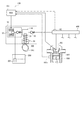
本発明の第1実施形態の燃料供給装置を含む全体構成を図1に示す。
本形態の燃料供給装置100は、高圧ポンプ10、電子制御装置(以下「ECU」という)101、及び、燃圧検出センサ102を備えている。
最初にプランジャ部30について説明する。プランジャ部30は、プランジャ31、プランジャ支持部32、オイルシール33、ロアシート34、リフター35、および、プランジャスプリング36を備えている。
調量弁部50は、ハウジング本体11によって形成される筒部51、筒部51の開口を覆う弁部カバー52、コネクタ53、および、コネクタハウジング54を備えている。
上述したように、燃料供給装置100は、ECU101を備えている。このECU101が、コネクタ53の端子53aに接続されて、コイル65への通電制御を行う。すなわち、調量弁部50のニードル64を制御する。
上述したように図1に示したカムシャフト300が回転すると、プランジャ31がその軸方向に往復移動する。プランジャ31は、図4中に「カムリフト」として示すごとく、上死点と下死点との間を往復移動する。ここでは(1)吸入行程、(2)戻し行程、(3)加圧行程に分けて説明する。
プランジャ31が図2の下方へ移動するとき(図4中のA→B)、コイル65への通電は停止される。そのため、吸入弁58は、スプリング67によって付勢されている可動コア68と一体のニードル64により加圧室14側へ移動している。このとき、可動コア68およびニードル64は「開側位置」にある。その結果、吸入弁58は、シートボデー56の座部69から離座する。これにより、燃料室13と加圧室14とが連通する。また、このとき、加圧室14の圧力は低下する。したがって、燃料室13の燃料は、加圧室14へ吸入される。
プランジャ31が下死点から上死点に向かって上昇をはじめると(図4中のB→C)、加圧室14の燃料の圧力は上昇し、吸入弁58には、加圧室14側の燃料から、シートボデー56の座部69に着座する方向へ力が加わる。しかし、コイル65に通電していないときは、ニードル64はスプリング67の付勢力により、加圧室14側へ移動している。これにより、コイル65に通電されていない状態では、吸入弁58はシートボデー56の座部69から離座した状態となる。その結果、加圧室14の燃料は、上述の吸入行程とは逆に、プランジャ31の上昇によって燃料室13へ戻される。
戻し行程の途中でコイル65への通電が行われると、コイル65に発生した磁界により磁気回路が形成される。すると、固定コア66と可動コア68との間に磁気吸引力が発生する。そして、固定コア66と可動コア68との間に発生する磁気吸引力がスプリング67の付勢力よりも大きくなると、可動コア68は固定コア66側へ移動する。そのため、可動コア68と一体のニードル64も、固定コア66側へ移動する。このとき可動コア68およびニードル64は「閉側位置」にある。ニードル64が固定コア66側へ移動すると、吸入弁58とニードル64とが離間する。その結果、吸入弁58は、スプリング61の付勢力および加圧室14側の燃料から受ける圧力により、シートボデー56の座部69へ着座する(図4中のC)。
なお、加圧室14の燃料の圧力が所定値まで上昇したとき、コイル65への通電は停止される。加圧室14の燃料の圧力が上昇すると、加圧室14側の燃料によって、吸入弁58は、シートボデー56の座部69に着座した状態で維持されるためである。
ここで、図3に示した燃圧制御部103の制御についてさらに具体的な説明を加える。
燃料の圧力を検出する燃圧検出センサ102からの信号に基づき、ECU101では、燃圧制御部103が駆動回路104へ第1駆動信号および第2駆動信号を出力することは既に述べた。燃圧制御部103は吸入弁58を閉弁するために図6中の時刻T1で第1駆動信号および第2駆動信号を共にハイレベルにするのであるが、この通電開始タイミング(時刻T1)は、燃圧検出センサ102にて検出される燃料の圧力を目標圧力とするようにフィードバック制御される。したがって、燃圧検出センサ102にて検出される燃料の圧力が低下していくと、時刻T1が時間的に進むことになる。すなわち、通電開始タイミングが「前出し」される。以下、燃圧制御部103からの第1駆動信号および第2駆動信号がハイレベルになる通電開始タイミングを「スピル弁閉弁時期epduty」という。なお、このスピル弁閉弁時期epdutyは、図4にDで示した上死点を基準にするものであり、閉弁時期が早くなると大きくなり、閉弁時期が遅くなると小さくなる。また、スピル弁閉弁時期epdutyが「通電開始タイミング」に相当する。
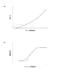
図11(a)に示すように、ポンプ回転数Npが高くなると、吸入弁58の閉弁力も大きくなることが知られている。ここでいうポンプ回転数Npとは、カムシャフトの回転数である。つまり、ポンプ回転数Npが大きくなると、プランジャ31による加圧室14の圧力上昇速度が大きくなるため、吸入弁58の閉弁力が増加するのである。そして、ポンプ回転数Npはエンジン回転数NEに比例するため、図11(b)に示すように、エンジン回転数NEが高くなると、ポンプ回転数Npが大きくなり、閉弁力が増加するため、振動振幅が大きくなる。すなわち、エンジン回転数が大きくなるほど、作動音が大きくなる。さらに、図11(b)に示すように、低回転域では、振動振幅が大きくならない。詳しくは、アイドル運転時には振動の悪化がなく、また、走行開始直後の急激な振動の悪化もない。そして、図11(a)に示したようにポンプ回転数Npが高くなると閉弁力が増加するため、吸入弁58の閉弁時期は時間的に進むことになる。したがって、エンジン低回転時に学習した通電時間Tvを高回転時に利用しても、吐出不良が起きることはない。これらの理由から、エンジン回転数が所定値以下である場合に学習制御を行うことが望ましい。
図12(a)は、図4に示したカムリフトの曲線に重ね、カム速度(プランジャ31の速度)の曲線を波線で示すものである。図中には、エンジン負荷をH1、H2、H3(H1<H2<H3)で示した。図12(a)から、エンジン負荷が高くなると、カム速度が大きくなることが分かる。このとき、図12(b)には、エンジンの負荷率と振動振幅との関係を、エンジン回転数NEが低速の場合と高速の場合とで示した。エンジン回転数NEが低速の場合、負荷が大きくなっても振動振幅の増加がほとんど生じていない。また、エンジン回転数NEが高速の場合、負荷が大きくなるとわずかに振動振幅の増加が見られる。また、エンジン低負荷時に学習した通電時間Tvを高負荷時に利用しても、上記エンジン回転数の場合と同様、吐出不良が起きることはない。これらの理由から、エンジン負荷が所定値以下である場合に学習制御を行うことが望ましい。
第2実施形態は、上記形態と、学習制御が異なっている。ここでは、上記形態と異なっている部分のみを説明し、上記形態と同様の構成の説明を割愛する。また、同様の構成部分については同一の符号を付す。
本形態においても、上述した実施形態と同様の効果が奏される。
第3実施形態は、上記形態と、学習制御が異なっている。ここでは、上記形態と異なっている部分のみを説明し、上記形態と同様の構成の説明を割愛する。また、同様の構成部分については同一の符号を付す。
本形態においても、上述した実施形態と同様の効果が奏される。
第4実施形態は、上記形態と、学習制御が異なっている。ここでは、上記形態と異なっている部分のみを説明し、上記形態と同様の構成の説明を割愛する。また、同様の構成部分については同一の符号を付す。
本形態においても、上記形態と同様の効果が奏される。
Claims (11)
- 車両に搭載されて用いられ、
外部から燃料が供給される供給部と、
前記供給部に連通する燃料通路に配置される弁部材と、
前記燃料通路の下流側に位置する加圧室にて加圧される燃料を吐出する吐出部と、
前記弁部材に当接可能で、閉側位置と開側位置との間を移動可能な可動部と、
前記可動部に対する磁気吸引力を発生させるためのコイルと、
前記可動部を前記開側位置から前記閉側位置まで移動させることが可能な第1駆動電流で前記コイルへ通電可能であるとともに、前記可動部を前記閉側位置に保持可能な前記第1駆動電流よりも小さな第2駆動電流で前記コイルへ通電可能な駆動回路部と、
前記第1駆動電流での通電による前記閉側位置への前記可動部の移動途中で、前記第2駆動電流での通電に切り換え、前記可動部を前記閉側位置へ移動させるよう前記駆動回路部を制御する駆動制御手段と、
を備えていることを特徴とする燃料供給装置。 - 請求項1に記載の燃料供給装置において、
前記吐出部から吐出される燃料の圧力を検出する燃圧検出手段を備え、
前記駆動制御手段は、前記燃圧検出手段にて検出される燃料の圧力低下に基づき、前記第1駆動電流での通電の開始タイミングを決定することを特徴とする燃料供給装置。 - 請求項1又は2に記載の燃料供給装置において、
前記コイルへの駆動電流を検出する電流検出手段を備え、
前記駆動制御手段は、前記電流検出手段にて検出される電流の低下に基づき、前記第1駆動電流での通電の開始タイミングを決定することを特徴とする燃料供給装置。 - 請求項1〜3のいずれか一項に記載の燃料供給装置において、
振動を検出する振動検出手段を備え、
前記駆動制御手段は、前記振動検出手段にて検出される振動の低下に基づき、前記第1駆動電流での通電の開始タイミングを決定することを特徴とする燃料供給装置。 - 請求項2〜4のいずれか一項に記載の燃料供給装置において、
前記駆動制御手段は、前記第1駆動電流での通電時間である第1通電時間を徐々に短くしていく学習制御を実行し、前記第1通電時間を設定することを特徴とする燃料供給装置。 - 請求項5に記載の燃料供給装置において、
前記駆動制御手段は、前記学習制御を実行し、前記通電開始タイミングの変化に基づき、前記第1通電時間を設定することを特徴とする燃料供給装置。 - 請求項5又は6に記載の燃料供給装置において、
前記駆動制御手段は、車両の運転条件に対応する複数の運転領域毎に、前記学習制御を実行し、前記第1通電時間を設定することを特徴とする燃料供給装置。 - 請求項7に記載の燃料供給装置において、
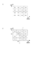
前記駆動制御手段は、前記第1通電時間が未設定の運転領域のうち、学習制御の対象となっている対象運転領域よりも前記第1通電時間が小さく設定されると推定される運転領域に対しては、前記対象運転領域に設定された前記第1通電時間を設定することを特徴とする燃料供給装置。 - 請求項5〜8のいずれか一項に記載の燃料供給装置において、
前記駆動制御手段は、定常状態の継続を条件として、前記学習制御を実行することを特徴とする燃料供給装置。 - 請求項5〜9のいずれか一項に記載の燃料供給装置において、
前記駆動制御手段は、前記学習制御の途中で車両の運転条件が変化した場合、前記学習制御を中止することを特徴とする燃料供給装置。 - 請求項5〜10のいずれか一項に記載の燃料供給装置において、
前記駆動制御手段は、前記可動部を前記開側位置から前記閉側位置まで移動させるのに要する前記第1駆動電流の通電時間を初期値として、前記学習制御を実行することを特徴とする燃料供給装置。
Priority Applications (4)
| Application Number | Priority Date | Filing Date | Title |
|---|---|---|---|
| JP2009069754A JP4587133B2 (ja) | 2008-06-04 | 2009-03-23 | 燃料供給装置 |
| DE102009026517.1A DE102009026517B4 (de) | 2008-06-04 | 2009-05-27 | Kraftstoffzufuhrvorrichtung |
| CN2009101413513A CN101598090B (zh) | 2008-06-04 | 2009-06-02 | 燃料供给装置 |
| US12/478,104 US7905215B2 (en) | 2008-06-04 | 2009-06-04 | Fuel supply apparatus |
Applications Claiming Priority (2)
| Application Number | Priority Date | Filing Date | Title |
|---|---|---|---|
| JP2008146468 | 2008-06-04 | ||
| JP2009069754A JP4587133B2 (ja) | 2008-06-04 | 2009-03-23 | 燃料供給装置 |
Publications (2)
| Publication Number | Publication Date |
|---|---|
| JP2010014109A true JP2010014109A (ja) | 2010-01-21 |
| JP4587133B2 JP4587133B2 (ja) | 2010-11-24 |
Family
ID=41269025
Family Applications (1)
| Application Number | Title | Priority Date | Filing Date |
|---|---|---|---|
| JP2009069754A Expired - Fee Related JP4587133B2 (ja) | 2008-06-04 | 2009-03-23 | 燃料供給装置 |
Country Status (4)
| Country | Link |
|---|---|
| US (1) | US7905215B2 (ja) |
| JP (1) | JP4587133B2 (ja) |
| CN (1) | CN101598090B (ja) |
| DE (1) | DE102009026517B4 (ja) |
Cited By (12)
| Publication number | Priority date | Publication date | Assignee | Title |
|---|---|---|---|---|
| JP2009293460A (ja) * | 2008-06-04 | 2009-12-17 | Denso Corp | 燃料供給装置 |
| JP2011231758A (ja) * | 2010-04-08 | 2011-11-17 | Denso Corp | 高圧ポンプ |
| JP2012246852A (ja) * | 2011-05-30 | 2012-12-13 | Hitachi Automotive Systems Ltd | 電磁駆動型の吸入弁を備えた高圧燃料供給ポンプ |
| JP2012255450A (ja) * | 2010-04-08 | 2012-12-27 | Denso Corp | 高圧ポンプ |
| CN102913359A (zh) * | 2011-08-03 | 2013-02-06 | 日立汽车系统株式会社 | 电磁阀的控制方法、电磁吸入阀的电磁驱动机构的控制装置 |
| JP2015014221A (ja) * | 2013-07-04 | 2015-01-22 | 株式会社デンソー | 高圧ポンプの制御装置 |
| JP2015161412A (ja) * | 2014-02-27 | 2015-09-07 | ローベルト ボツシユ ゲゼルシヤフト ミツト ベシユレンクテル ハフツングRobert Bosch Gmbh | 切替可能な弁の制御方法、該方法を実施可能なコンピュータプログラム、該コンピュータプログラムが格納された記憶媒体、該記憶媒体を含む電子制御装置 |
| WO2017069052A1 (ja) * | 2015-10-22 | 2017-04-27 | 株式会社デンソー | 高圧ポンプの制御装置 |
| JP2017214852A (ja) * | 2016-05-31 | 2017-12-07 | 日立オートモティブシステムズ株式会社 | 高圧燃料供給ポンプの制御装置、及び高圧燃料供給ポンプ |
| JP2018200053A (ja) * | 2018-08-24 | 2018-12-20 | 株式会社デンソー | 燃料噴射制御装置および燃料噴射システム |
| US10557445B2 (en) | 2015-01-21 | 2020-02-11 | Hitachi Automotive Systems, Ltd | High-pressure fuel supply device for internal combustion engine |
| WO2021171775A1 (ja) * | 2020-02-28 | 2021-09-02 | 日立Astemo株式会社 | 高圧燃料ポンプの制御装置 |
Families Citing this family (8)
| Publication number | Priority date | Publication date | Assignee | Title |
|---|---|---|---|---|
| US8662056B2 (en) * | 2010-12-30 | 2014-03-04 | Delphi Technologies, Inc. | Fuel pressure control system and method having a variable pull-in time interval based pressure |
| US9341181B2 (en) | 2012-03-16 | 2016-05-17 | Denso Corporation | Control device of high pressure pump |
| DE102012211798B4 (de) * | 2012-07-06 | 2019-12-05 | Robert Bosch Gmbh | Verfahren zur Betätigung eines Schaltelements einer Ventileinrichtung |
| DE102015208573B3 (de) | 2015-05-08 | 2016-06-16 | Continental Automotive Gmbh | Druckbestimmung in einem Kraftstoff-Einspritzventil |
| JP6535737B2 (ja) * | 2015-07-09 | 2019-06-26 | 日立オートモティブシステムズ株式会社 | 燃料噴射装置の制御装置 |
| JP6464076B2 (ja) * | 2015-11-17 | 2019-02-06 | ヤンマー株式会社 | 燃料噴射ポンプ |
| JP7172756B2 (ja) * | 2019-03-08 | 2022-11-16 | 株式会社デンソー | 高圧ポンプの制御装置 |
| DE102021208758A1 (de) | 2021-08-11 | 2023-02-16 | Robert Bosch Gesellschaft mit beschränkter Haftung | Verfahren zum Betreiben einer Hochdruckpumpe |
Citations (10)
| Publication number | Priority date | Publication date | Assignee | Title |
|---|---|---|---|---|
| JPH05272390A (ja) * | 1992-03-26 | 1993-10-19 | Zexel Corp | 燃料噴射装置 |
| JPH09100938A (ja) * | 1995-10-05 | 1997-04-15 | Denso Corp | 電磁弁駆動装置 |
| JPH09151768A (ja) * | 1995-11-29 | 1997-06-10 | Denso Corp | 燃料噴射装置の電磁弁制御装置 |
| JPH11117795A (ja) * | 1997-08-16 | 1999-04-27 | Robert Bosch Gmbh | 負荷の制御のための方法及び装置 |
| JP2000136747A (ja) * | 1998-11-04 | 2000-05-16 | Denso Corp | ディーゼルエンジンの電子制御式燃料噴射装置 |
| WO2004001220A1 (ja) * | 2002-06-20 | 2003-12-31 | Hitachi, Ltd. | 内燃機関の高圧燃料ポンプ制御装置 |
| JP2005171936A (ja) * | 2003-12-12 | 2005-06-30 | Hitachi Ltd | エンジンの高圧燃料ポンプ制御装置 |
| JP2007146657A (ja) * | 2005-11-24 | 2007-06-14 | Denso Corp | 燃料噴射制御装置 |
| JP2007231929A (ja) * | 2006-02-03 | 2007-09-13 | Denso Corp | デューティ比制御装置 |
| JP2007327409A (ja) * | 2006-06-07 | 2007-12-20 | Toyota Motor Corp | 内燃機関の燃料供給装置 |
Family Cites Families (20)
| Publication number | Priority date | Publication date | Assignee | Title |
|---|---|---|---|---|
| JPS6321346A (ja) | 1986-07-12 | 1988-01-28 | Diesel Kiki Co Ltd | 燃料噴射装置 |
| DE3843138A1 (de) | 1988-12-22 | 1990-06-28 | Bosch Gmbh Robert | Verfahren zur steuerung und erfassung der bewegung eines ankers eines elektromagnetischen schaltorgans |
| DE69320830T2 (de) | 1992-03-26 | 1999-01-14 | Zexel Corp., Tokio/Tokyo | Kraftstoff-Einspritzvorrichtung |
| US5377068A (en) * | 1992-10-19 | 1994-12-27 | Predator Systems Inc. | Electromagnet with holding control |
| GB9413684D0 (en) * | 1994-07-07 | 1994-08-24 | Lucas Ind Plc | Drive circuit |
| DE4433209C2 (de) * | 1994-09-17 | 2000-02-03 | Mtu Friedrichshafen Gmbh | Einrichtung zur Erkennung des Ankeraufprallzeitpunktes bei Entstromung eines Magnetventils |
| GB9420617D0 (en) * | 1994-10-13 | 1994-11-30 | Lucas Ind Plc | Drive circuit |
| DE19526683A1 (de) * | 1995-07-21 | 1997-01-23 | Fev Motorentech Gmbh & Co Kg | Verfahren zur Erkennung des Ankerauftreffens an einem elektromagnetisch betätigbaren Stellmittel |
| DE19530121A1 (de) * | 1995-08-16 | 1997-02-20 | Fev Motorentech Gmbh & Co Kg | Verfahren zur Reduzierung der Auftreffgeschwindigkeit eines Ankers an einem elektromagnetischen Aktuator |
| JP3613885B2 (ja) * | 1996-05-24 | 2005-01-26 | 国産電機株式会社 | 内燃機関用インジェクタの駆動制御方法及び駆動制御装置 |
| JP2963407B2 (ja) * | 1997-02-14 | 1999-10-18 | 本田技研工業株式会社 | 燃料噴射弁制御装置 |
| DE19719602A1 (de) * | 1997-05-09 | 1998-11-12 | Fahrzeugklimaregelung Gmbh | Elektronische Steuerschaltung |
| DE19745536C1 (de) * | 1997-10-15 | 1999-05-27 | Siemens Ag | Verfahren zum Steuern eines elektromechanischen Stellgeräts |
| US6167869B1 (en) * | 1997-11-03 | 2001-01-02 | Caterpillar Inc. | Fuel injector utilizing a multiple current level solenoid |
| US5986871A (en) * | 1997-11-04 | 1999-11-16 | Caterpillar Inc. | Method of operating a fuel injector |
| US6123092A (en) * | 1997-11-04 | 2000-09-26 | Honda Giken Kogyo Kabushiki Kaisha | Electromagnetic solenoid valve drive circuit |
| JP3579398B2 (ja) * | 2002-01-25 | 2004-10-20 | 三菱電機株式会社 | 位置決め制御装置 |
| US6957655B2 (en) * | 2002-09-20 | 2005-10-25 | Advanced Neuromodulation Systems, Inc. | Apparatus for dosage control |
| JP4483770B2 (ja) | 2005-11-18 | 2010-06-16 | 株式会社デンソー | 電磁弁異常診断方法 |
| DE102006002717B3 (de) * | 2006-01-19 | 2007-05-24 | Siemens Ag | Verfahren und Vorrichtung zum Ansteuern eines Ventils eines Kraftstoffdampf-Rückhaltesystems |
-
2009
- 2009-03-23 JP JP2009069754A patent/JP4587133B2/ja not_active Expired - Fee Related
- 2009-05-27 DE DE102009026517.1A patent/DE102009026517B4/de not_active Expired - Fee Related
- 2009-06-02 CN CN2009101413513A patent/CN101598090B/zh active Active
- 2009-06-04 US US12/478,104 patent/US7905215B2/en not_active Expired - Fee Related
Patent Citations (10)
| Publication number | Priority date | Publication date | Assignee | Title |
|---|---|---|---|---|
| JPH05272390A (ja) * | 1992-03-26 | 1993-10-19 | Zexel Corp | 燃料噴射装置 |
| JPH09100938A (ja) * | 1995-10-05 | 1997-04-15 | Denso Corp | 電磁弁駆動装置 |
| JPH09151768A (ja) * | 1995-11-29 | 1997-06-10 | Denso Corp | 燃料噴射装置の電磁弁制御装置 |
| JPH11117795A (ja) * | 1997-08-16 | 1999-04-27 | Robert Bosch Gmbh | 負荷の制御のための方法及び装置 |
| JP2000136747A (ja) * | 1998-11-04 | 2000-05-16 | Denso Corp | ディーゼルエンジンの電子制御式燃料噴射装置 |
| WO2004001220A1 (ja) * | 2002-06-20 | 2003-12-31 | Hitachi, Ltd. | 内燃機関の高圧燃料ポンプ制御装置 |
| JP2005171936A (ja) * | 2003-12-12 | 2005-06-30 | Hitachi Ltd | エンジンの高圧燃料ポンプ制御装置 |
| JP2007146657A (ja) * | 2005-11-24 | 2007-06-14 | Denso Corp | 燃料噴射制御装置 |
| JP2007231929A (ja) * | 2006-02-03 | 2007-09-13 | Denso Corp | デューティ比制御装置 |
| JP2007327409A (ja) * | 2006-06-07 | 2007-12-20 | Toyota Motor Corp | 内燃機関の燃料供給装置 |
Cited By (23)
| Publication number | Priority date | Publication date | Assignee | Title |
|---|---|---|---|---|
| JP2009293460A (ja) * | 2008-06-04 | 2009-12-17 | Denso Corp | 燃料供給装置 |
| JP2011231758A (ja) * | 2010-04-08 | 2011-11-17 | Denso Corp | 高圧ポンプ |
| JP2012255450A (ja) * | 2010-04-08 | 2012-12-27 | Denso Corp | 高圧ポンプ |
| JP2012246852A (ja) * | 2011-05-30 | 2012-12-13 | Hitachi Automotive Systems Ltd | 電磁駆動型の吸入弁を備えた高圧燃料供給ポンプ |
| US9726104B2 (en) | 2011-08-03 | 2017-08-08 | Hitachi Automotive Systems, Ltd. | Control method of magnetic solenoid valve, control method of electromagnetically controlled inlet valve of high pressure fuel pump, and control device for electromagnetic actuator of electromagnetically controlled inlet valve |
| CN102913359A (zh) * | 2011-08-03 | 2013-02-06 | 日立汽车系统株式会社 | 电磁阀的控制方法、电磁吸入阀的电磁驱动机构的控制装置 |
| JP2013032750A (ja) * | 2011-08-03 | 2013-02-14 | Hitachi Automotive Systems Ltd | 電磁弁の制御方法、高圧燃料供給ポンプの電磁吸入弁の制御方法および電磁吸入弁の電磁駆動機構の制御装置 |
| JP2015014221A (ja) * | 2013-07-04 | 2015-01-22 | 株式会社デンソー | 高圧ポンプの制御装置 |
| JP2015161412A (ja) * | 2014-02-27 | 2015-09-07 | ローベルト ボツシユ ゲゼルシヤフト ミツト ベシユレンクテル ハフツングRobert Bosch Gmbh | 切替可能な弁の制御方法、該方法を実施可能なコンピュータプログラム、該コンピュータプログラムが格納された記憶媒体、該記憶媒体を含む電子制御装置 |
| US10557445B2 (en) | 2015-01-21 | 2020-02-11 | Hitachi Automotive Systems, Ltd | High-pressure fuel supply device for internal combustion engine |
| WO2017069052A1 (ja) * | 2015-10-22 | 2017-04-27 | 株式会社デンソー | 高圧ポンプの制御装置 |
| JP2017082597A (ja) * | 2015-10-22 | 2017-05-18 | 株式会社デンソー | 高圧ポンプの制御装置 |
| US10982638B2 (en) | 2016-05-31 | 2021-04-20 | Hitachi Automotive Systems, Ltd. | Device for controlling high-pressure fuel supply pump, and high-pressure fuel supply pump |
| JP2017214852A (ja) * | 2016-05-31 | 2017-12-07 | 日立オートモティブシステムズ株式会社 | 高圧燃料供給ポンプの制御装置、及び高圧燃料供給ポンプ |
| WO2017208565A1 (ja) * | 2016-05-31 | 2017-12-07 | 日立オートモティブシステムズ株式会社 | 高圧燃料供給ポンプの制御装置、及び高圧燃料供給ポンプ |
| CN109072843A (zh) * | 2016-05-31 | 2018-12-21 | 日立汽车系统株式会社 | 高压燃料供给泵的控制装置和高压燃料供给泵 |
| JP2018200053A (ja) * | 2018-08-24 | 2018-12-20 | 株式会社デンソー | 燃料噴射制御装置および燃料噴射システム |
| WO2021171775A1 (ja) * | 2020-02-28 | 2021-09-02 | 日立Astemo株式会社 | 高圧燃料ポンプの制御装置 |
| JP2021134760A (ja) * | 2020-02-28 | 2021-09-13 | 日立Astemo株式会社 | 高圧燃料ポンプの制御装置 |
| CN114829764A (zh) * | 2020-02-28 | 2022-07-29 | 日立安斯泰莫株式会社 | 高压燃料泵的控制装置 |
| JP7303764B2 (ja) | 2020-02-28 | 2023-07-05 | 日立Astemo株式会社 | 高圧燃料ポンプの制御装置 |
| CN114829764B (zh) * | 2020-02-28 | 2023-12-05 | 日立安斯泰莫株式会社 | 高压燃料泵的控制装置 |
| US11852093B2 (en) | 2020-02-28 | 2023-12-26 | Hitachi Astemo, Ltd. | Control device for high-pressure fuel pump |
Also Published As
| Publication number | Publication date |
|---|---|
| CN101598090A (zh) | 2009-12-09 |
| US20090301439A1 (en) | 2009-12-10 |
| JP4587133B2 (ja) | 2010-11-24 |
| US7905215B2 (en) | 2011-03-15 |
| CN101598090B (zh) | 2011-09-14 |
| DE102009026517B4 (de) | 2022-01-13 |
| DE102009026517A1 (de) | 2009-12-10 |
Similar Documents
| Publication | Publication Date | Title |
|---|---|---|
| JP4587133B2 (ja) | 燃料供給装置 | |
| CN102656361B (zh) | 内燃机的燃料供给装置及燃料供给控制方法 | |
| CN103080528B (zh) | 内燃机的燃料喷射控制系统 | |
| JP2010248997A (ja) | 燃料ポンプの制御装置 | |
| EP2038535B1 (en) | Fuel supply apparatus and fuel supply method of an internal combustion engine | |
| US7918208B2 (en) | Fuel supply apparatus | |
| JP6569542B2 (ja) | 高圧ポンプ制御装置 | |
| JP4941679B2 (ja) | 燃料供給装置 | |
| JP2011132872A (ja) | 燃料圧力制御装置 | |
| JP2013231362A (ja) | 燃料圧力制御装置 | |
| JP2013199916A (ja) | 内燃機関の燃料噴射システム | |
| JP4572950B2 (ja) | コモンレール圧制御装置およびそれを用いた燃料噴射システム | |
| JP4716140B2 (ja) | 燃料供給装置 | |
| JP5991268B2 (ja) | 内燃機関の燃料供給装置 | |
| JP2009293459A (ja) | 燃料供給装置 | |
| JP4386016B2 (ja) | 燃料噴射制御装置 | |
| JP5835117B2 (ja) | 内燃機関の燃料供給制御装置 | |
| JP2011196262A (ja) | 燃料圧力制御装置 | |
| WO2019230589A1 (ja) | 燃料噴射弁の制御装置、及び燃料噴射システム | |
| JP5217514B2 (ja) | エンジンの燃料供給装置 | |
| JP2006002698A (ja) | 燃料噴射装置 | |
| JP2009228535A (ja) | 燃料残量検出装置およびそれを用いた燃料噴射システム | |
| JP6341176B2 (ja) | 高圧ポンプの制御装置 | |
| JP2015161297A (ja) | 燃料供給装置 | |
| JP2006348770A (ja) | 蓄圧式燃料噴射装置 |
Legal Events
| Date | Code | Title | Description |
|---|---|---|---|
| A977 | Report on retrieval |
Free format text: JAPANESE INTERMEDIATE CODE: A971007 Effective date: 20100416 |
|
| A131 | Notification of reasons for refusal |
Free format text: JAPANESE INTERMEDIATE CODE: A131 Effective date: 20100423 |
|
| A521 | Request for written amendment filed |
Free format text: JAPANESE INTERMEDIATE CODE: A523 Effective date: 20100604 |
|
| TRDD | Decision of grant or rejection written | ||
| A01 | Written decision to grant a patent or to grant a registration (utility model) |
Free format text: JAPANESE INTERMEDIATE CODE: A01 Effective date: 20100816 |
|
| A01 | Written decision to grant a patent or to grant a registration (utility model) |
Free format text: JAPANESE INTERMEDIATE CODE: A01 |
|
| A61 | First payment of annual fees (during grant procedure) |
Free format text: JAPANESE INTERMEDIATE CODE: A61 Effective date: 20100829 |
|
| R151 | Written notification of patent or utility model registration |
Ref document number: 4587133 Country of ref document: JP Free format text: JAPANESE INTERMEDIATE CODE: R151 |
|
| FPAY | Renewal fee payment (event date is renewal date of database) |
Free format text: PAYMENT UNTIL: 20130917 Year of fee payment: 3 |
|
| R250 | Receipt of annual fees |
Free format text: JAPANESE INTERMEDIATE CODE: R250 |
|
| R250 | Receipt of annual fees |
Free format text: JAPANESE INTERMEDIATE CODE: R250 |
|
| R250 | Receipt of annual fees |
Free format text: JAPANESE INTERMEDIATE CODE: R250 |
|
| R250 | Receipt of annual fees |
Free format text: JAPANESE INTERMEDIATE CODE: R250 |
|
| R250 | Receipt of annual fees |
Free format text: JAPANESE INTERMEDIATE CODE: R250 |
|
| R250 | Receipt of annual fees |
Free format text: JAPANESE INTERMEDIATE CODE: R250 |
|
| R250 | Receipt of annual fees |
Free format text: JAPANESE INTERMEDIATE CODE: R250 |
|
| R250 | Receipt of annual fees |
Free format text: JAPANESE INTERMEDIATE CODE: R250 |
|
| LAPS | Cancellation because of no payment of annual fees |