JP2005291317A - プーリ構造 - Google Patents
プーリ構造 Download PDFInfo
- Publication number
- JP2005291317A JP2005291317A JP2004105769A JP2004105769A JP2005291317A JP 2005291317 A JP2005291317 A JP 2005291317A JP 2004105769 A JP2004105769 A JP 2004105769A JP 2004105769 A JP2004105769 A JP 2004105769A JP 2005291317 A JP2005291317 A JP 2005291317A
- Authority
- JP
- Japan
- Prior art keywords
- movable pulley
- pulley
- peripheral surface
- rotary shaft
- rotating shaft
- Prior art date
- Legal status (The legal status is an assumption and is not a legal conclusion. Google has not performed a legal analysis and makes no representation as to the accuracy of the status listed.)
- Pending
Links
Images
Classifications
-
- F—MECHANICAL ENGINEERING; LIGHTING; HEATING; WEAPONS; BLASTING
- F16—ENGINEERING ELEMENTS AND UNITS; GENERAL MEASURES FOR PRODUCING AND MAINTAINING EFFECTIVE FUNCTIONING OF MACHINES OR INSTALLATIONS; THERMAL INSULATION IN GENERAL
- F16H—GEARING
- F16H63/00—Control outputs from the control unit to change-speed- or reversing-gearings for conveying rotary motion or to other devices than the final output mechanism
- F16H63/02—Final output mechanisms therefor; Actuating means for the final output mechanisms
- F16H63/04—Final output mechanisms therefor; Actuating means for the final output mechanisms a single final output mechanism being moved by a single final actuating mechanism
- F16H63/06—Final output mechanisms therefor; Actuating means for the final output mechanisms a single final output mechanism being moved by a single final actuating mechanism the final output mechanism having an indefinite number of positions
- F16H63/065—Final output mechanisms therefor; Actuating means for the final output mechanisms a single final output mechanism being moved by a single final actuating mechanism the final output mechanism having an indefinite number of positions hydraulic actuating means
-
- F—MECHANICAL ENGINEERING; LIGHTING; HEATING; WEAPONS; BLASTING
- F16—ENGINEERING ELEMENTS AND UNITS; GENERAL MEASURES FOR PRODUCING AND MAINTAINING EFFECTIVE FUNCTIONING OF MACHINES OR INSTALLATIONS; THERMAL INSULATION IN GENERAL
- F16H—GEARING
- F16H55/00—Elements with teeth or friction surfaces for conveying motion; Worms, pulleys or sheaves for gearing mechanisms
- F16H55/32—Friction members
- F16H55/52—Pulleys or friction discs of adjustable construction
- F16H55/56—Pulleys or friction discs of adjustable construction of which the bearing parts are relatively axially adjustable
Landscapes
- Engineering & Computer Science (AREA)
- General Engineering & Computer Science (AREA)
- Mechanical Engineering (AREA)
- Transmissions By Endless Flexible Members (AREA)
- Pulleys (AREA)
Abstract
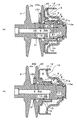
【解決手段】 回転軸21と、この回転軸外周に固定状態に設けられた固定プーリ2と、回転軸の外周に固定プーリ2とシーブ面が対向するように配置され、回転軸に対して軸方向に摺動可能に嵌め合わされた可動プーリ22と、この可動プーリの背面側内周面と回転軸の外周面間に設けられ、可動プーリの回転を規制するボールスプライン3と、可動プーリの背面側に形成された可動プーリ駆動用の作動液室5とを備え、可動プーリのシーブ面側内周面と、このシーブ面側内周面と対向する前記回転軸外周面との間の微小な隙間が、作動液室5のシール部6とされたプーリ構造において、スプライン3の嵌合径D1とシール部6の嵌合径D2とを同一とする。
【選択図】 図1
Description
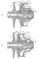
即ち、回転軸1と、この回転軸1の一端側(図中左側)外周に固定状態(図では一体)に設けられた固定プーリ2と、回転軸1の他端側(図中右側)外周に固定プーリ2とシーブ面が対向するように配置され、回転軸1に対してボール等のスプライン3により回転を規制されて連結されて軸方向に摺動可能とされた可動プーリ4と、この可動プーリ4の背面側(図中右側)に形成された可動プーリ駆動用の作動液室5とを備え、可動プーリ4のシーブ面側(図中左側)内周面と、このシーブ面側内周面と対向する回転軸1の外周面との間の微小な隙間が、作動液室5のシール部6とされた構成となっていた。
なお、スプライン3は、回転軸1の周方向における例えば3箇所に設けられており、回転軸1の外周に形成された軸側溝7と、可動プーリ4の内周に形成されたボス側溝8と、これら軸側溝7及びボス側溝8により形成される軸方向の棒状空間に複数装填された例えばボール状の転動部材9と、この転動部材9の脱落を防止すべく可動プーリ4の背面側(図中右側)内周と回転軸1の所定位置(軸側溝7の終端側)とに装着されたスナップリング10、11とより構成される。
そこで本発明は、上述した問題が解消され、小型化が図れるとともに、シール部からの漏れ量の低減及び均一化が実現できて、変速動作の制御性向上等が図れるプーリ構造を提供することを目的としている。
前記スプラインの嵌合径と前記シール部の嵌合径とを同一としたことを特徴とするものである。
なお、可動プーリ4のスプライン3が形成される背面側内周の実際の内径が、回転軸1のシール部6を構成する外周の実際の外径よりも小さいと、閉方向のストロークエンドに向かって可動プーリが移動する際に、これら内外径が干渉するのを避けるため、前述の第2段部1bのような逃げが必要となる。また、可動プーリ4のシール部6を構成するシーブ面側内周の実際の内径が、回転軸1のスプライン3が形成される部分の実際の外径よりも小さいと、可動プーリを固定プーリに対して嵌め合わせる組立作業が実現不可能となる。
また、「ボール等のスプライン」とは、ボールスプライン又はコロスプライン、或いはこれらと同様の構造のスプライン(軸とボスの間にボール状又は円筒状などの転動体を装填した構造により、回転を規制しつつ軸方向の相対動作を許容する機械要素)である。
また、上記空きスペースの少なくとも一部を利用して、シール部の最小長さLS1(図1(a)に示す)を従来より長く確保することができるため、例えば図1に示すような逃げ22bを可動プーリに形成することによって、シール部の最大長さLS2(図1(b)に示す)と上記最小長さLS1との差をゼロ又はゼロに近い値とすることが容易に可能となる。このため、作動液の供給量を低減できるとともに、シール部からの作動液の漏れ量が可動プーリの位置によって変動する問題を解消できるか又は格段に改善できる。
本例は、既述した図2の構成に本発明を適用したものであり、図2の構成と同様の要素には同符号を使用して重複する説明を省略する。なお、無段変速装置の全体構成等については、前述の特許文献等に開示された公知例と同様でよいので、説明を省略する。
本例のプーリ構造は、図1に示す回転軸21と可動プーリ22とを有する。回転軸21と可動プーリ22の各嵌合径D1,D2は、既述した意味において同一(D1=D2)とされている。またこれにより、回転軸21は、前述の第1段部1aに相当する第1段部21aを有するが、前述の第2段部1bに相当する段部(逃げ)の無い構成となっている。そして、このような段部の無い構成により、可動プーリ22の軸方向長さLP2(いいかえると、図1(a)の如く開方向ストロークエンドにある可動プーリ22のシーブ面22aの内周位置から、第1段部21aまでの距離寸法)が、図2(a)に示す従来の可動プーリ4の軸方向長さLP1よりも短縮されている。
なお従来、可動プーリ4のボス側溝8は、ブローチ加工により行なわれていたが、本例の可動プーリ22のボス側溝8は、通常の切削加工(例えば、フライス、ギヤシェーパ、スロッタなどによる加工)により行なえばよい。
なお、図2に示したような段部1bの有る構成であっても、可動プーリ4の内周に上記逃げ22bと同様の逃げを形成することによって、シール部6の長さ(即ちシール長)を均一化することは可能である。しかしこの場合、シール長は常に最小長さLS1(或いはそれに近い値)となるため、最小長さLS1をある程度長く確保できること(即ち、作動液の漏れ量がいつも許容量以下となるようなシール長が維持できること)が必要となるが、従来では軸方向に余裕スペースが無いため、このような条件を満足することが困難であった。しかし、本発明を適用すれば軸方向に余裕スペースが生まれるため、このような事情が格段に改善される。
例えば、上記形態例(図1)では、段部1bが不要となったことにより得られた軸方向のスペースを主に軸方向の小型化に利用しているが、本発明はこのような態様に限定されない。得られた空きスペースを利用して、他の部材を配置したり、他の部材を軸方向に大きくして余裕を持たせたりしてもよいことは、当然である。
また、従来の嵌合径D2を縮径して嵌合径D1と同一としてもよい。このようにすると、各プーリのシーブ面を中心軸側に拡大することが可能となる。
また、本発明の思想は、入力側のプーリ(いわゆるプライマリプーリ)と出力側のプーリ(いわゆるセカンダリプーリ)のうちの、何れか一方に適用してもよいし、両方に適用することもできる。
また、本発明のプーリ構造は、車両以外の変速機構にも適用可能であることは、いうまでもない。
2a,22a シーブ面
3 スプライン
5 作動液室
6 シール部
D1,D2 嵌合径
Claims (1)
- 回転軸と、この回転軸外周に固定状態に設けられた固定プーリと、前記回転軸の外周に前記固定プーリとシーブ面が対向するように配置され、前記回転軸に対して軸方向に摺動可能に嵌め合わされた可動プーリと、この可動プーリの背面側内周面と前記回転軸の外周面間に設けられ、前記可動プーリの回転を規制するボール等のスプラインと、前記可動プーリの背面側に形成された可動プーリ駆動用の作動液室とを備え、前記可動プーリのシーブ面側内周面と、このシーブ面側内周面と対向する前記回転軸外周面との間の微小な隙間が、前記作動液室のシール部とされたプーリ構造において、
前記スプラインの嵌合径と前記シール部の嵌合径とを同一としたことを特徴とするプーリ構造。
Priority Applications (4)
| Application Number | Priority Date | Filing Date | Title |
|---|---|---|---|
| JP2004105769A JP2005291317A (ja) | 2004-03-31 | 2004-03-31 | プーリ構造 |
| KR1020040102721A KR100692338B1 (ko) | 2004-03-31 | 2004-12-08 | 풀리 구조 |
| EP05005129A EP1582773A3 (en) | 2004-03-31 | 2005-03-09 | Pulley structure |
| US11/086,407 US20050233844A1 (en) | 2004-03-31 | 2005-03-23 | Pulley structure |
Applications Claiming Priority (1)
| Application Number | Priority Date | Filing Date | Title |
|---|---|---|---|
| JP2004105769A JP2005291317A (ja) | 2004-03-31 | 2004-03-31 | プーリ構造 |
Publications (1)
| Publication Number | Publication Date |
|---|---|
| JP2005291317A true JP2005291317A (ja) | 2005-10-20 |
Family
ID=34880076
Family Applications (1)
| Application Number | Title | Priority Date | Filing Date |
|---|---|---|---|
| JP2004105769A Pending JP2005291317A (ja) | 2004-03-31 | 2004-03-31 | プーリ構造 |
Country Status (4)
| Country | Link |
|---|---|
| US (1) | US20050233844A1 (ja) |
| EP (1) | EP1582773A3 (ja) |
| JP (1) | JP2005291317A (ja) |
| KR (1) | KR100692338B1 (ja) |
Cited By (2)
| Publication number | Priority date | Publication date | Assignee | Title |
|---|---|---|---|---|
| DE112009000032T5 (de) | 2008-02-28 | 2010-08-19 | Aisin Aw Co., Ltd. | Riemenscheibenaufbau und stufenlos einstellbares Getriebe der Riemenbauart |
| JP2019218177A (ja) * | 2018-06-19 | 2019-12-26 | 三菱電機ビルテクノサービス株式会社 | 主ロープ補償装置 |
Families Citing this family (6)
| Publication number | Priority date | Publication date | Assignee | Title |
|---|---|---|---|---|
| US7517295B2 (en) * | 2005-12-14 | 2009-04-14 | Luk Lamellen Und Kupplungsbau Beteiligungs Kg | Conical disk pair for a belt-driven conical-pulley transmission |
| JP4670904B2 (ja) * | 2008-05-30 | 2011-04-13 | トヨタ自動車株式会社 | 無段変速機 |
| CN102859235B (zh) * | 2009-09-15 | 2016-02-24 | 研究业务流程重组财团-舍布鲁克大学法律部 | 用于无级变速器的驱动带轮 |
| US9644717B2 (en) | 2011-03-22 | 2017-05-09 | Bombardier Recreational Products Inc. | Continuously variable transmission driving pulley |
| JP5342585B2 (ja) * | 2011-03-23 | 2013-11-13 | ジヤトコ株式会社 | ベルト式無段変速機 |
| MX2025000837A (es) * | 2024-01-23 | 2025-08-01 | Polaris Inc | Transmision mecanica continuamente variable asistida |
Family Cites Families (18)
| Publication number | Priority date | Publication date | Assignee | Title |
|---|---|---|---|---|
| NL175096C (nl) * | 1974-11-15 | 1984-09-17 | Doornes Transmissie Bv | Traploos variabele drijfriemoverbrenging met hydraulische drukregeling van de zijdelingse aandrukkracht op de drijfriem of schakelband. |
| JPS5680551A (en) * | 1979-12-05 | 1981-07-01 | Aisin Warner Ltd | Belt driven type stepless speed changer with self-aligning mechanism |
| EP0043641A2 (en) * | 1980-06-19 | 1982-01-13 | General Motors Corporation | Variable-ratio power transmission mechanisms |
| JPS6165953A (ja) * | 1984-09-08 | 1986-04-04 | Daihatsu Motor Co Ltd | Vベルト式無段変速機のシ−ル構造 |
| JPH0784902B2 (ja) * | 1985-05-02 | 1995-09-13 | 本田技研工業株式会社 | 可動プーリ |
| US4735598A (en) * | 1985-07-10 | 1988-04-05 | Aisin-Warner Kabushiki Kaisha | Continuously variable V-belt transmission |
| JPH01171954U (ja) * | 1988-05-25 | 1989-12-06 | ||
| JPH0280845A (ja) * | 1988-09-16 | 1990-03-20 | Toyota Motor Corp | 車両用ベルト式無段変速機 |
| JPH02190621A (ja) * | 1989-01-14 | 1990-07-26 | Toyota Motor Corp | ローラスプライン装置 |
| JPH0348148U (ja) * | 1989-09-19 | 1991-05-08 | ||
| JPH04107351A (ja) * | 1990-08-28 | 1992-04-08 | Nissan Motor Co Ltd | 無段変速v溝プーリ |
| JP3306217B2 (ja) * | 1994-04-04 | 2002-07-24 | 愛知機械工業株式会社 | 無段変速機のパーキング機構 |
| JPH10169736A (ja) * | 1996-12-06 | 1998-06-26 | Nissan Motor Co Ltd | 無段変速機の可変プーリ |
| US6132093A (en) * | 1997-06-16 | 2000-10-17 | Thk, Co., Ltd. | Linear motion guiding apparatus |
| JP3186650B2 (ja) | 1997-06-27 | 2001-07-11 | 日産自動車株式会社 | Vベルト式無段変速機構 |
| JP4752089B2 (ja) * | 2000-05-17 | 2011-08-17 | トヨタ自動車株式会社 | ベルト式無段変速機 |
| JP3750523B2 (ja) * | 2000-12-12 | 2006-03-01 | トヨタ自動車株式会社 | 車両用無段変速機の変速制御装置 |
| JP4003747B2 (ja) | 2004-01-14 | 2007-11-07 | 株式会社竹屋 | 遊技機 |
-
2004
- 2004-03-31 JP JP2004105769A patent/JP2005291317A/ja active Pending
- 2004-12-08 KR KR1020040102721A patent/KR100692338B1/ko not_active Expired - Fee Related
-
2005
- 2005-03-09 EP EP05005129A patent/EP1582773A3/en not_active Withdrawn
- 2005-03-23 US US11/086,407 patent/US20050233844A1/en not_active Abandoned
Cited By (4)
| Publication number | Priority date | Publication date | Assignee | Title |
|---|---|---|---|---|
| DE112009000032T5 (de) | 2008-02-28 | 2010-08-19 | Aisin Aw Co., Ltd. | Riemenscheibenaufbau und stufenlos einstellbares Getriebe der Riemenbauart |
| US8152665B2 (en) | 2008-02-28 | 2012-04-10 | Aisin Aw Co., Ltd | Pulley structure and belt-type continuously variable transmission |
| DE112009000032B4 (de) * | 2008-02-28 | 2013-04-25 | Aisin Aw Co., Ltd. | Riemenscheibenaufbau und stufenlos einstellbares Getriebe der Riemenbauart |
| JP2019218177A (ja) * | 2018-06-19 | 2019-12-26 | 三菱電機ビルテクノサービス株式会社 | 主ロープ補償装置 |
Also Published As
| Publication number | Publication date |
|---|---|
| EP1582773A3 (en) | 2007-03-28 |
| EP1582773A2 (en) | 2005-10-05 |
| KR100692338B1 (ko) | 2007-03-13 |
| KR20050096827A (ko) | 2005-10-06 |
| US20050233844A1 (en) | 2005-10-20 |
Similar Documents
| Publication | Publication Date | Title |
|---|---|---|
| JP4670904B2 (ja) | 無段変速機 | |
| JP7001837B2 (ja) | 無段変速機 | |
| KR100952868B1 (ko) | 벨트식 무단 변속기 | |
| JP2005291317A (ja) | プーリ構造 | |
| JP6206298B2 (ja) | クラッチ装置 | |
| JP6782182B2 (ja) | 湿式多板クラッチ | |
| JP6173814B2 (ja) | クラッチ | |
| US20050233847A1 (en) | Belt type continuously variable transmission | |
| CN112639331B (zh) | 无级变速器 | |
| JP2009275718A (ja) | 無段変速機 | |
| JP6779083B2 (ja) | トルクコンバータ | |
| JP2005344922A (ja) | ベルト式無段変速機 | |
| JP4891284B2 (ja) | ベルト式無段変速機 | |
| JP6366645B2 (ja) | ベアリングの潤滑構造 | |
| JP6721481B2 (ja) | 無段変速機のプーリ | |
| JP5969431B2 (ja) | 無段変速機 | |
| JP6654931B2 (ja) | 可動装置および無段変速機 | |
| JP2009103166A (ja) | ベルト式無段変速機 | |
| JP2013087794A (ja) | 乾式ベルト式無段変速機 | |
| JP2013047534A (ja) | ベルト式無段変速機のシール構造 | |
| JP2010196776A (ja) | 無段変速機 | |
| JP2008286082A (ja) | ポンプ | |
| JP2013104526A (ja) | ベルト式無段変速機 | |
| JP2020090995A (ja) | 車両用ベルト式無段変速機 | |
| JP2009174635A (ja) | ベルト式無段変速機 |
Legal Events
| Date | Code | Title | Description |
|---|---|---|---|
| A621 | Written request for application examination |
Free format text: JAPANESE INTERMEDIATE CODE: A621 Effective date: 20050818 |
|
| A977 | Report on retrieval |
Free format text: JAPANESE INTERMEDIATE CODE: A971007 Effective date: 20070628 |
|
| A131 | Notification of reasons for refusal |
Free format text: JAPANESE INTERMEDIATE CODE: A131 Effective date: 20070703 |
|
| A521 | Written amendment |
Free format text: JAPANESE INTERMEDIATE CODE: A523 Effective date: 20070822 |
|
| A02 | Decision of refusal |
Free format text: JAPANESE INTERMEDIATE CODE: A02 Effective date: 20071114 |