JP2005291276A - 流体封入式能動型防振装置 - Google Patents
流体封入式能動型防振装置 Download PDFInfo
- Publication number
- JP2005291276A JP2005291276A JP2004104299A JP2004104299A JP2005291276A JP 2005291276 A JP2005291276 A JP 2005291276A JP 2004104299 A JP2004104299 A JP 2004104299A JP 2004104299 A JP2004104299 A JP 2004104299A JP 2005291276 A JP2005291276 A JP 2005291276A
- Authority
- JP
- Japan
- Prior art keywords
- vibration
- fluid
- vibration plate
- pressure receiving
- axial direction
- Prior art date
- Legal status (The legal status is an assumption and is not a legal conclusion. Google has not performed a legal analysis and makes no representation as to the accuracy of the status listed.)
- Granted
Links
Images
Landscapes
- Combined Devices Of Dampers And Springs (AREA)
Abstract
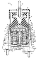
【解決手段】 第二の取付部材14で支持せしめられて受圧室42,48の壁部の一部を構成する仕切部材40を設けて、該仕切部材40に透孔110を形成すると共に、該透孔110内に加振板112を嵌め入れて軸方向に変位可能に組み付ける一方、仕切部材40を挟んで受圧室42,48と反対側には、壁部の一部が可撓性膜26で構成されて非圧縮性流体が封入されることにより容積可変の平衡室44を形成すると共に、該平衡室44を受圧室42,48に連通するオリフィス通路58を設けた。
【選択図】 図1
Description
本発明の態様1の特徴とするところは、第一の取付部材と第二の取付部材を本体ゴム弾性体で連結することにより、該本体ゴム弾性体で壁部の一部が構成されて振動が入力される受圧室を形成し、該受圧室に非圧縮性流体を封入する一方、該受圧室の壁部の別の一部を変位可能に弾性支持された加振板で構成すると共に、該加振板を挟んで該受圧室と反対側に電磁式駆動手段を配設して、該電磁式駆動手段におけるコイル部材への通電によって駆動せしめられる出力部材を該加振板に連結し、該コイル部材への通電により該加振板を加振駆動せしめることにより該受圧室を圧力制御するようにした流体封入式能動型防振装置において、前記第二の取付部材で支持せしめられて前記受圧室の壁部の一部を構成する仕切部材を設けて、該仕切部材に透孔を形成すると共に、該透孔内に前記加振板を嵌め入れて軸方向に変位可能に組み付ける一方、該仕切部材を挟んで該受圧室と反対側には、壁部の一部が可撓性膜で構成されて非圧縮性流体が封入されることにより容積可変の平衡室を形成すると共に、該平衡室を前記受圧室に連通させるオリフィス通路を設けた流体封入式能動型防振装置にある。
本発明の態様2の特徴とするところは、本発明の前記態様1に係る流体封入式能動型防振装置において、前記可撓性膜が、その外周縁部において前記第二の取付部材に対して流体密に固着されていると共に、該可撓性膜の中央部分に対して連結部材が固着されており、該連結部材が前記加振板に重ね合わされて固定されていることにある。
本発明の態様3の特徴とするところは、本発明の前記態様1又は2に係る流体封入式能動型防振装置において、前記仕切部材には、前記透孔の周縁部において軸方向に立ち上がる円筒形状のガイドスリーブが形成されている一方、前記加振板の外周縁部には、軸方向に延び出す円筒形状のリム部が形成されており、該リム部が該ガイドスリーブに嵌め入れられて軸方向に変位せしめられるようになっていることにある。
本発明の態様4の特徴とするところは、本発明の前記態様1乃至3の何れかに係る流体封入式能動型防振装置において、前記出力部材には、前記加振板から軸方向外方に向かって突出する駆動ロッドが形成されていると共に、該駆動ロッドが、軸方向に離隔する少なくとも二箇所において、軸直角方向に広がる弾性支持部材によって、前記第二の取付部材に対して弾性的に位置決め支持されていることにある。
本発明の態様5の特徴とするところは、本発明の前記態様4に係る流体封入式能動型防振装置において、前記弾性支持部材が、軸直角方向に広がる金属製の板ばねによって構成されていることにある。
本発明の態様6の特徴とするところは、本発明の前記態様1乃至5の何れかに係る流体封入式能動型防振装置において、前記加振板の外周縁部と前記透孔の縁部の間に周方向の全周に亘って隙間が形成されていることにある。
12 第一の取付金具
14 第二の取付金具
16 本体ゴム弾性体
26 ダイヤフラム
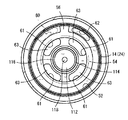
40 仕切金具
42 主液室
44 平衡室
48 副液室
58 オリフィス通路
66 駆動ロッド
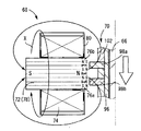
68 電磁式アクチュエータ
70 可動部材
74 コイル
110 透孔
Claims (6)
- 第一の取付部材と第二の取付部材を本体ゴム弾性体で連結することにより、該本体ゴム弾性体で壁部の一部が構成されて振動が入力される受圧室を形成し、該受圧室に非圧縮性流体を封入する一方、該受圧室の壁部の別の一部を変位可能に弾性支持された加振板で構成すると共に、該加振板を挟んで該受圧室と反対側に電磁式駆動手段を配設して、該電磁式駆動手段におけるコイル部材への通電によって駆動せしめられる出力部材を該加振板に連結し、該コイル部材への通電により該加振板を加振駆動せしめることにより該受圧室を圧力制御するようにした流体封入式能動型防振装置において、
前記第二の取付部材で支持せしめられて前記受圧室の壁部の一部を構成する仕切部材を設けて、該仕切部材に透孔を形成すると共に、該透孔内に前記加振板を嵌め入れて軸方向に変位可能に組み付ける一方、該仕切部材を挟んで該受圧室と反対側には、壁部の一部が可撓性膜で構成されて非圧縮性流体が封入されることにより容積可変の平衡室を形成すると共に、該平衡室を前記受圧室に連通させるオリフィス通路を設けたことを特徴とする流体封入式能動型防振装置。 - 前記可撓性膜が、その外周縁部において前記第二の取付部材に対して流体密に固着されていると共に、該可撓性膜の中央部分に対して連結部材が固着されており、該連結部材が前記加振板に重ね合わされて固定されている請求項1に記載の流体封入式能動型防振装置。
- 前記仕切部材には、前記透孔の周縁部において軸方向に立ち上がる円筒形状のガイドスリーブが形成されている一方、前記加振板の外周縁部には、軸方向に延び出す円筒形状のリム部が形成されており、該リム部が該ガイドスリーブに嵌め入れられて軸方向に変位せしめられるようになっている請求項1又は2に記載の流体封入式能動型防振装置。
- 前記出力部材には、前記加振板から軸方向外方に向かって突出する駆動ロッドが形成されていると共に、該駆動ロッドが、軸方向に離隔する少なくとも二箇所において、軸直角方向に広がる弾性支持部材によって、前記第二の取付部材に対して弾性的に位置決め支持されている請求項1乃至3の何れかに記載の流体封入式能動型防振装置。
- 前記弾性支持部材が、軸直角方向に広がる金属製の板ばねによって構成されている請求項4に記載の流体封入式防振型防振装置。
- 前記加振板の外周縁部と前記透孔の縁部の間に周方向の全周に亘って隙間が形成されている請求項1乃至5の何れかに記載の流体封入式能動型防振装置。
Priority Applications (1)
| Application Number | Priority Date | Filing Date | Title |
|---|---|---|---|
| JP2004104299A JP4123179B2 (ja) | 2004-03-31 | 2004-03-31 | 流体封入式能動型防振装置 |
Applications Claiming Priority (1)
| Application Number | Priority Date | Filing Date | Title |
|---|---|---|---|
| JP2004104299A JP4123179B2 (ja) | 2004-03-31 | 2004-03-31 | 流体封入式能動型防振装置 |
Publications (2)
| Publication Number | Publication Date |
|---|---|
| JP2005291276A true JP2005291276A (ja) | 2005-10-20 |
| JP4123179B2 JP4123179B2 (ja) | 2008-07-23 |
Family
ID=35324447
Family Applications (1)
| Application Number | Title | Priority Date | Filing Date |
|---|---|---|---|
| JP2004104299A Expired - Fee Related JP4123179B2 (ja) | 2004-03-31 | 2004-03-31 | 流体封入式能動型防振装置 |
Country Status (1)
| Country | Link |
|---|---|
| JP (1) | JP4123179B2 (ja) |
Cited By (10)
| Publication number | Priority date | Publication date | Assignee | Title |
|---|---|---|---|---|
| JP2009092237A (ja) * | 2007-09-21 | 2009-04-30 | Tokai Rubber Ind Ltd | 流体封入式防振装置 |
| JP2009092235A (ja) * | 2007-09-21 | 2009-04-30 | Tokai Rubber Ind Ltd | 流体封入式防振装置 |
| JP2009092236A (ja) * | 2007-09-21 | 2009-04-30 | Tokai Rubber Ind Ltd | 流体封入式防振装置 |
| JP2009162281A (ja) * | 2007-12-28 | 2009-07-23 | Tokai Rubber Ind Ltd | 能動型流体封入式防振装置 |
| JP2009162282A (ja) * | 2007-12-28 | 2009-07-23 | Tokai Rubber Ind Ltd | 防振装置用板ばねとそれを用いた能動型流体封入式防振装置や能動型制振装置、電磁式アクチュエータ |
| US8047513B2 (en) | 2007-09-21 | 2011-11-01 | Tokai Rubber Industries, Ltd. | Fluid filled type vibration damping device |
| US8100388B2 (en) | 2008-05-29 | 2012-01-24 | Hyundai Motor Company | Electromagnetic active engine mount apparatus |
| US8172209B2 (en) | 2007-09-21 | 2012-05-08 | Tokai Rubber Industries, Ltd. | Fluid filled type vibration damping device |
| JP2012097795A (ja) * | 2010-10-30 | 2012-05-24 | Toyo Tire & Rubber Co Ltd | 能動型液封入式防振装置 |
| JP5899296B1 (ja) * | 2014-11-26 | 2016-04-06 | 住友理工株式会社 | 防振用電磁式アクチュエータと、それを用いた能動型流体封入式防振装置および能動型制振装置 |
-
2004
- 2004-03-31 JP JP2004104299A patent/JP4123179B2/ja not_active Expired - Fee Related
Cited By (14)
| Publication number | Priority date | Publication date | Assignee | Title |
|---|---|---|---|---|
| US8172209B2 (en) | 2007-09-21 | 2012-05-08 | Tokai Rubber Industries, Ltd. | Fluid filled type vibration damping device |
| JP2009092235A (ja) * | 2007-09-21 | 2009-04-30 | Tokai Rubber Ind Ltd | 流体封入式防振装置 |
| JP2009092236A (ja) * | 2007-09-21 | 2009-04-30 | Tokai Rubber Ind Ltd | 流体封入式防振装置 |
| US8047513B2 (en) | 2007-09-21 | 2011-11-01 | Tokai Rubber Industries, Ltd. | Fluid filled type vibration damping device |
| JP2009092237A (ja) * | 2007-09-21 | 2009-04-30 | Tokai Rubber Ind Ltd | 流体封入式防振装置 |
| JP2009162281A (ja) * | 2007-12-28 | 2009-07-23 | Tokai Rubber Ind Ltd | 能動型流体封入式防振装置 |
| JP2009162282A (ja) * | 2007-12-28 | 2009-07-23 | Tokai Rubber Ind Ltd | 防振装置用板ばねとそれを用いた能動型流体封入式防振装置や能動型制振装置、電磁式アクチュエータ |
| US8100388B2 (en) | 2008-05-29 | 2012-01-24 | Hyundai Motor Company | Electromagnetic active engine mount apparatus |
| JP2012097795A (ja) * | 2010-10-30 | 2012-05-24 | Toyo Tire & Rubber Co Ltd | 能動型液封入式防振装置 |
| JP5899296B1 (ja) * | 2014-11-26 | 2016-04-06 | 住友理工株式会社 | 防振用電磁式アクチュエータと、それを用いた能動型流体封入式防振装置および能動型制振装置 |
| WO2016084559A1 (ja) * | 2014-11-26 | 2016-06-02 | 住友理工株式会社 | 防振用電磁式アクチュエータと、それを用いた能動型流体封入式防振装置および能動型制振装置 |
| CN106461000A (zh) * | 2014-11-26 | 2017-02-22 | 住友理工株式会社 | 隔振用电磁式致动器、使用其的能动型流体封入式隔振装置以及能动型减振装置 |
| CN106461000B (zh) * | 2014-11-26 | 2018-06-12 | 住友理工株式会社 | 隔振用电磁式致动器、使用其的能动型流体封入式隔振装置以及能动型减振装置 |
| US10100897B2 (en) | 2014-11-26 | 2018-10-16 | Sumitomo Riko Company Limited | Vibration-damping electromagnetic actuator, active fluid-filled vibration-damping device and active vibration-damping device using the same |
Also Published As
| Publication number | Publication date |
|---|---|
| JP4123179B2 (ja) | 2008-07-23 |
Similar Documents
| Publication | Publication Date | Title |
|---|---|---|
| JP4120828B2 (ja) | 流体封入式能動型防振装置 | |
| JP3972210B2 (ja) | 流体封入式能動型防振装置 | |
| JP5568472B2 (ja) | 流体封入式防振装置 | |
| EP0945643B1 (en) | Fluid-filled active vibration damping device including oscillating member oscillated by actuator controlled with pulse signal | |
| JP5641525B2 (ja) | 流体封入式能動型防振装置 | |
| JP4123179B2 (ja) | 流体封入式能動型防振装置 | |
| JP3503288B2 (ja) | 流体封入式防振装置 | |
| JP5226599B2 (ja) | 防振装置 | |
| JP4258847B2 (ja) | 流体封入式能動型防振装置 | |
| JPH05164179A (ja) | 流体封入式防振装置 | |
| JP3778013B2 (ja) | 流体封入式防振装置 | |
| JP2618784B2 (ja) | 流体封入式防振装置 | |
| JP2010270785A (ja) | 液封入式防振装置 | |
| JP3873618B2 (ja) | 能動型防振用加振器およびそれを用いた能動型防振装置 | |
| JP2007218418A (ja) | 能動型液封入式防振装置 | |
| JP4075062B2 (ja) | 能動型流体封入式防振装置 | |
| JPH10267072A (ja) | 流体封入式防振装置 | |
| JP4123177B2 (ja) | 流体封入式能動型防振装置 | |
| JP4079072B2 (ja) | 能動型流体封入式防振装置 | |
| JP5002176B2 (ja) | 電磁式能動型マウント | |
| JP5033082B2 (ja) | 能動型液封入式防振装置 | |
| JP4088795B2 (ja) | 流体封入式能動型防振装置 | |
| JP3620369B2 (ja) | 流体封入式能動的マウント | |
| JP2827844B2 (ja) | 流体封入式マウント装置 | |
| JP3116558B2 (ja) | 位相変換型流体封入式防振装置 |
Legal Events
| Date | Code | Title | Description |
|---|---|---|---|
| A621 | Written request for application examination |
Free format text: JAPANESE INTERMEDIATE CODE: A621 Effective date: 20060823 |
|
| A977 | Report on retrieval |
Free format text: JAPANESE INTERMEDIATE CODE: A971007 Effective date: 20070510 |
|
| A131 | Notification of reasons for refusal |
Free format text: JAPANESE INTERMEDIATE CODE: A131 Effective date: 20070516 |
|
| A521 | Written amendment |
Free format text: JAPANESE INTERMEDIATE CODE: A523 Effective date: 20070713 |
|
| TRDD | Decision of grant or rejection written | ||
| A01 | Written decision to grant a patent or to grant a registration (utility model) |
Free format text: JAPANESE INTERMEDIATE CODE: A01 Effective date: 20080408 |
|
| A01 | Written decision to grant a patent or to grant a registration (utility model) |
Free format text: JAPANESE INTERMEDIATE CODE: A01 |
|
| A61 | First payment of annual fees (during grant procedure) |
Free format text: JAPANESE INTERMEDIATE CODE: A61 Effective date: 20080421 |
|
| R150 | Certificate of patent or registration of utility model |
Free format text: JAPANESE INTERMEDIATE CODE: R150 |
|
| FPAY | Renewal fee payment (event date is renewal date of database) |
Free format text: PAYMENT UNTIL: 20110516 Year of fee payment: 3 |
|
| FPAY | Renewal fee payment (event date is renewal date of database) |
Free format text: PAYMENT UNTIL: 20110516 Year of fee payment: 3 |
|
| FPAY | Renewal fee payment (event date is renewal date of database) |
Free format text: PAYMENT UNTIL: 20120516 Year of fee payment: 4 |
|
| FPAY | Renewal fee payment (event date is renewal date of database) |
Free format text: PAYMENT UNTIL: 20120516 Year of fee payment: 4 |
|
| FPAY | Renewal fee payment (event date is renewal date of database) |
Free format text: PAYMENT UNTIL: 20130516 Year of fee payment: 5 |
|
| FPAY | Renewal fee payment (event date is renewal date of database) |
Free format text: PAYMENT UNTIL: 20140516 Year of fee payment: 6 |
|
| LAPS | Cancellation because of no payment of annual fees |