EP4537867A2 - Nierensteinbehandlungssystem - Google Patents
Nierensteinbehandlungssystem Download PDFInfo
- Publication number
- EP4537867A2 EP4537867A2 EP25154833.5A EP25154833A EP4537867A2 EP 4537867 A2 EP4537867 A2 EP 4537867A2 EP 25154833 A EP25154833 A EP 25154833A EP 4537867 A2 EP4537867 A2 EP 4537867A2
- Authority
- EP
- European Patent Office
- Prior art keywords
- irrigation
- trigger
- vacuum
- kidney stone
- tube
- Prior art date
- Legal status (The legal status is an assumption and is not a legal conclusion. Google has not performed a legal analysis and makes no representation as to the accuracy of the status listed.)
- Pending
Links
Images


Classifications
-
- A—HUMAN NECESSITIES
- A61—MEDICAL OR VETERINARY SCIENCE; HYGIENE
- A61B—DIAGNOSIS; SURGERY; IDENTIFICATION
- A61B1/00—Instruments for performing medical examinations of the interior of cavities or tubes of the body by visual or photographical inspection, e.g. endoscopes; Illuminating arrangements therefor
- A61B1/00064—Constructional details of the endoscope body
- A61B1/00071—Insertion part of the endoscope body
- A61B1/0008—Insertion part of the endoscope body characterised by distal tip features
- A61B1/00091—Nozzles
-
- A—HUMAN NECESSITIES
- A61—MEDICAL OR VETERINARY SCIENCE; HYGIENE
- A61B—DIAGNOSIS; SURGERY; IDENTIFICATION
- A61B1/00—Instruments for performing medical examinations of the interior of cavities or tubes of the body by visual or photographical inspection, e.g. endoscopes; Illuminating arrangements therefor
- A61B1/012—Instruments for performing medical examinations of the interior of cavities or tubes of the body by visual or photographical inspection, e.g. endoscopes; Illuminating arrangements therefor characterised by internal passages or accessories therefor
- A61B1/015—Control of fluid supply or evacuation
-
- A—HUMAN NECESSITIES
- A61—MEDICAL OR VETERINARY SCIENCE; HYGIENE
- A61B—DIAGNOSIS; SURGERY; IDENTIFICATION
- A61B1/00—Instruments for performing medical examinations of the interior of cavities or tubes of the body by visual or photographical inspection, e.g. endoscopes; Illuminating arrangements therefor
- A61B1/307—Instruments for performing medical examinations of the interior of cavities or tubes of the body by visual or photographical inspection, e.g. endoscopes; Illuminating arrangements therefor for the urinary organs, e.g. urethroscopes, cystoscopes
-
- A—HUMAN NECESSITIES
- A61—MEDICAL OR VETERINARY SCIENCE; HYGIENE
- A61B—DIAGNOSIS; SURGERY; IDENTIFICATION
- A61B17/00—Surgical instruments, devices or methods
- A61B17/22—Implements for squeezing-off ulcers or the like on inner organs of the body; Implements for scraping-out cavities of body organs, e.g. bones; for invasive removal or destruction of calculus using mechanical vibrations; for removing obstructions in blood vessels, not otherwise provided for
-
- A—HUMAN NECESSITIES
- A61—MEDICAL OR VETERINARY SCIENCE; HYGIENE
- A61B—DIAGNOSIS; SURGERY; IDENTIFICATION
- A61B18/00—Surgical instruments, devices or methods for transferring non-mechanical forms of energy to or from the body
- A61B18/18—Surgical instruments, devices or methods for transferring non-mechanical forms of energy to or from the body by applying electromagnetic radiation, e.g. microwaves
- A61B18/20—Surgical instruments, devices or methods for transferring non-mechanical forms of energy to or from the body by applying electromagnetic radiation, e.g. microwaves using laser
- A61B18/22—Surgical instruments, devices or methods for transferring non-mechanical forms of energy to or from the body by applying electromagnetic radiation, e.g. microwaves using laser the beam being directed along or through a flexible conduit, e.g. an optical fibre; Couplings or hand-pieces therefor
- A61B18/26—Surgical instruments, devices or methods for transferring non-mechanical forms of energy to or from the body by applying electromagnetic radiation, e.g. microwaves using laser the beam being directed along or through a flexible conduit, e.g. an optical fibre; Couplings or hand-pieces therefor for producing a shock wave, e.g. laser lithotripsy
-
- A—HUMAN NECESSITIES
- A61—MEDICAL OR VETERINARY SCIENCE; HYGIENE
- A61M—DEVICES FOR INTRODUCING MEDIA INTO, OR ONTO, THE BODY; DEVICES FOR TRANSDUCING BODY MEDIA OR FOR TAKING MEDIA FROM THE BODY; DEVICES FOR PRODUCING OR ENDING SLEEP OR STUPOR
- A61M1/00—Suction or pumping devices for medical purposes; Devices for carrying-off, for treatment of, or for carrying-over, body-liquids; Drainage systems
- A61M1/71—Suction drainage systems
- A61M1/74—Suction control
- A61M1/741—Suction control with means for varying suction manually
- A61M1/7413—Suction control with means for varying suction manually by changing the cross-section of the line
- A61M1/7415—Suction control with means for varying suction manually by changing the cross-section of the line by deformation of the fluid passage
-
- A—HUMAN NECESSITIES
- A61—MEDICAL OR VETERINARY SCIENCE; HYGIENE
- A61M—DEVICES FOR INTRODUCING MEDIA INTO, OR ONTO, THE BODY; DEVICES FOR TRANSDUCING BODY MEDIA OR FOR TAKING MEDIA FROM THE BODY; DEVICES FOR PRODUCING OR ENDING SLEEP OR STUPOR
- A61M1/00—Suction or pumping devices for medical purposes; Devices for carrying-off, for treatment of, or for carrying-over, body-liquids; Drainage systems
- A61M1/71—Suction drainage systems
- A61M1/77—Suction-irrigation systems
- A61M1/774—Handpieces specially adapted for providing suction as well as irrigation, either simultaneously or independently
-
- A—HUMAN NECESSITIES
- A61—MEDICAL OR VETERINARY SCIENCE; HYGIENE
- A61M—DEVICES FOR INTRODUCING MEDIA INTO, OR ONTO, THE BODY; DEVICES FOR TRANSDUCING BODY MEDIA OR FOR TAKING MEDIA FROM THE BODY; DEVICES FOR PRODUCING OR ENDING SLEEP OR STUPOR
- A61M3/00—Medical syringes, e.g. enemata; Irrigators
- A61M3/02—Enemata; Irrigators
- A61M3/0204—Physical characteristics of the irrigation fluid, e.g. conductivity or turbidity
- A61M3/0208—Physical characteristics of the irrigation fluid, e.g. conductivity or turbidity before use
-
- A—HUMAN NECESSITIES
- A61—MEDICAL OR VETERINARY SCIENCE; HYGIENE
- A61M—DEVICES FOR INTRODUCING MEDIA INTO, OR ONTO, THE BODY; DEVICES FOR TRANSDUCING BODY MEDIA OR FOR TAKING MEDIA FROM THE BODY; DEVICES FOR PRODUCING OR ENDING SLEEP OR STUPOR
- A61M3/00—Medical syringes, e.g. enemata; Irrigators
- A61M3/02—Enemata; Irrigators
- A61M3/0204—Physical characteristics of the irrigation fluid, e.g. conductivity or turbidity
- A61M3/022—Volume; Flow rate
-
- A—HUMAN NECESSITIES
- A61—MEDICAL OR VETERINARY SCIENCE; HYGIENE
- A61M—DEVICES FOR INTRODUCING MEDIA INTO, OR ONTO, THE BODY; DEVICES FOR TRANSDUCING BODY MEDIA OR FOR TAKING MEDIA FROM THE BODY; DEVICES FOR PRODUCING OR ENDING SLEEP OR STUPOR
- A61M3/00—Medical syringes, e.g. enemata; Irrigators
- A61M3/02—Enemata; Irrigators
- A61M3/0233—Enemata; Irrigators characterised by liquid supply means, e.g. from pressurised reservoirs
-
- A—HUMAN NECESSITIES
- A61—MEDICAL OR VETERINARY SCIENCE; HYGIENE
- A61B—DIAGNOSIS; SURGERY; IDENTIFICATION
- A61B1/00—Instruments for performing medical examinations of the interior of cavities or tubes of the body by visual or photographical inspection, e.g. endoscopes; Illuminating arrangements therefor
- A61B1/04—Instruments for performing medical examinations of the interior of cavities or tubes of the body by visual or photographical inspection, e.g. endoscopes; Illuminating arrangements therefor combined with photographic or television appliances
- A61B1/05—Instruments for performing medical examinations of the interior of cavities or tubes of the body by visual or photographical inspection, e.g. endoscopes; Illuminating arrangements therefor combined with photographic or television appliances characterised by the image sensor, e.g. camera, being in the distal end portion
-
- A—HUMAN NECESSITIES
- A61—MEDICAL OR VETERINARY SCIENCE; HYGIENE
- A61B—DIAGNOSIS; SURGERY; IDENTIFICATION
- A61B1/00—Instruments for performing medical examinations of the interior of cavities or tubes of the body by visual or photographical inspection, e.g. endoscopes; Illuminating arrangements therefor
- A61B1/06—Instruments for performing medical examinations of the interior of cavities or tubes of the body by visual or photographical inspection, e.g. endoscopes; Illuminating arrangements therefor with illuminating arrangements
- A61B1/0661—Endoscope light sources
- A61B1/0676—Endoscope light sources at distal tip of an endoscope
-
- A—HUMAN NECESSITIES
- A61—MEDICAL OR VETERINARY SCIENCE; HYGIENE
- A61B—DIAGNOSIS; SURGERY; IDENTIFICATION
- A61B18/00—Surgical instruments, devices or methods for transferring non-mechanical forms of energy to or from the body
- A61B18/18—Surgical instruments, devices or methods for transferring non-mechanical forms of energy to or from the body by applying electromagnetic radiation, e.g. microwaves
- A61B18/20—Surgical instruments, devices or methods for transferring non-mechanical forms of energy to or from the body by applying electromagnetic radiation, e.g. microwaves using laser
- A61B18/22—Surgical instruments, devices or methods for transferring non-mechanical forms of energy to or from the body by applying electromagnetic radiation, e.g. microwaves using laser the beam being directed along or through a flexible conduit, e.g. an optical fibre; Couplings or hand-pieces therefor
-
- A—HUMAN NECESSITIES
- A61—MEDICAL OR VETERINARY SCIENCE; HYGIENE
- A61B—DIAGNOSIS; SURGERY; IDENTIFICATION
- A61B17/00—Surgical instruments, devices or methods
- A61B17/00234—Surgical instruments, devices or methods for minimally invasive surgery
- A61B2017/00292—Surgical instruments, devices or methods for minimally invasive surgery mounted on or guided by flexible, e.g. catheter-like, means
- A61B2017/003—Steerable
-
- A—HUMAN NECESSITIES
- A61—MEDICAL OR VETERINARY SCIENCE; HYGIENE
- A61B—DIAGNOSIS; SURGERY; IDENTIFICATION
- A61B17/00—Surgical instruments, devices or methods
- A61B17/22—Implements for squeezing-off ulcers or the like on inner organs of the body; Implements for scraping-out cavities of body organs, e.g. bones; for invasive removal or destruction of calculus using mechanical vibrations; for removing obstructions in blood vessels, not otherwise provided for
- A61B2017/22079—Implements for squeezing-off ulcers or the like on inner organs of the body; Implements for scraping-out cavities of body organs, e.g. bones; for invasive removal or destruction of calculus using mechanical vibrations; for removing obstructions in blood vessels, not otherwise provided for with suction of debris
-
- A—HUMAN NECESSITIES
- A61—MEDICAL OR VETERINARY SCIENCE; HYGIENE
- A61B—DIAGNOSIS; SURGERY; IDENTIFICATION
- A61B17/00—Surgical instruments, devices or methods
- A61B17/32—Surgical cutting instruments
- A61B17/320068—Surgical cutting instruments using mechanical vibrations, e.g. ultrasonic
- A61B2017/320084—Irrigation sleeves
-
- A—HUMAN NECESSITIES
- A61—MEDICAL OR VETERINARY SCIENCE; HYGIENE
- A61B—DIAGNOSIS; SURGERY; IDENTIFICATION
- A61B17/00—Surgical instruments, devices or methods
- A61B17/32—Surgical cutting instruments
- A61B17/320068—Surgical cutting instruments using mechanical vibrations, e.g. ultrasonic
- A61B2017/320088—Surgical cutting instruments using mechanical vibrations, e.g. ultrasonic with acoustic insulation, e.g. elements for damping vibrations between horn and surrounding sheath
-
- A—HUMAN NECESSITIES
- A61—MEDICAL OR VETERINARY SCIENCE; HYGIENE
- A61B—DIAGNOSIS; SURGERY; IDENTIFICATION
- A61B18/00—Surgical instruments, devices or methods for transferring non-mechanical forms of energy to or from the body
- A61B2018/00053—Mechanical features of the instrument of device
- A61B2018/00184—Moving parts
- A61B2018/00196—Moving parts reciprocating lengthwise
-
- A—HUMAN NECESSITIES
- A61—MEDICAL OR VETERINARY SCIENCE; HYGIENE
- A61B—DIAGNOSIS; SURGERY; IDENTIFICATION
- A61B18/00—Surgical instruments, devices or methods for transferring non-mechanical forms of energy to or from the body
- A61B2018/00315—Surgical instruments, devices or methods for transferring non-mechanical forms of energy to or from the body for treatment of particular body parts
- A61B2018/00505—Urinary tract
- A61B2018/00511—Kidney
-
- A—HUMAN NECESSITIES
- A61—MEDICAL OR VETERINARY SCIENCE; HYGIENE
- A61B—DIAGNOSIS; SURGERY; IDENTIFICATION
- A61B18/00—Surgical instruments, devices or methods for transferring non-mechanical forms of energy to or from the body
- A61B2018/00571—Surgical instruments, devices or methods for transferring non-mechanical forms of energy to or from the body for achieving a particular surgical effect
- A61B2018/00577—Ablation
-
- A—HUMAN NECESSITIES
- A61—MEDICAL OR VETERINARY SCIENCE; HYGIENE
- A61B—DIAGNOSIS; SURGERY; IDENTIFICATION
- A61B18/00—Surgical instruments, devices or methods for transferring non-mechanical forms of energy to or from the body
- A61B2018/00636—Sensing and controlling the application of energy
- A61B2018/00696—Controlled or regulated parameters
- A61B2018/00744—Fluid flow
-
- A—HUMAN NECESSITIES
- A61—MEDICAL OR VETERINARY SCIENCE; HYGIENE
- A61B—DIAGNOSIS; SURGERY; IDENTIFICATION
- A61B18/00—Surgical instruments, devices or methods for transferring non-mechanical forms of energy to or from the body
- A61B2018/0091—Handpieces of the surgical instrument or device
-
- A—HUMAN NECESSITIES
- A61—MEDICAL OR VETERINARY SCIENCE; HYGIENE
- A61B—DIAGNOSIS; SURGERY; IDENTIFICATION
- A61B18/00—Surgical instruments, devices or methods for transferring non-mechanical forms of energy to or from the body
- A61B18/18—Surgical instruments, devices or methods for transferring non-mechanical forms of energy to or from the body by applying electromagnetic radiation, e.g. microwaves
- A61B18/20—Surgical instruments, devices or methods for transferring non-mechanical forms of energy to or from the body by applying electromagnetic radiation, e.g. microwaves using laser
- A61B18/22—Surgical instruments, devices or methods for transferring non-mechanical forms of energy to or from the body by applying electromagnetic radiation, e.g. microwaves using laser the beam being directed along or through a flexible conduit, e.g. an optical fibre; Couplings or hand-pieces therefor
- A61B18/26—Surgical instruments, devices or methods for transferring non-mechanical forms of energy to or from the body by applying electromagnetic radiation, e.g. microwaves using laser the beam being directed along or through a flexible conduit, e.g. an optical fibre; Couplings or hand-pieces therefor for producing a shock wave, e.g. laser lithotripsy
- A61B2018/263—Surgical instruments, devices or methods for transferring non-mechanical forms of energy to or from the body by applying electromagnetic radiation, e.g. microwaves using laser the beam being directed along or through a flexible conduit, e.g. an optical fibre; Couplings or hand-pieces therefor for producing a shock wave, e.g. laser lithotripsy the conversion of laser energy into mechanical shockwaves taking place in a liquid
-
- A—HUMAN NECESSITIES
- A61—MEDICAL OR VETERINARY SCIENCE; HYGIENE
- A61B—DIAGNOSIS; SURGERY; IDENTIFICATION
- A61B90/00—Instruments, implements or accessories specially adapted for surgery or diagnosis and not covered by any of the groups A61B1/00 - A61B50/00, e.g. for luxation treatment or for protecting wound edges
- A61B90/08—Accessories or related features not otherwise provided for
- A61B2090/0807—Indication means
- A61B2090/0811—Indication means for the position of a particular part of an instrument with respect to the rest of the instrument, e.g. position of the anvil of a stapling instrument
-
- A—HUMAN NECESSITIES
- A61—MEDICAL OR VETERINARY SCIENCE; HYGIENE
- A61B—DIAGNOSIS; SURGERY; IDENTIFICATION
- A61B90/00—Instruments, implements or accessories specially adapted for surgery or diagnosis and not covered by any of the groups A61B1/00 - A61B50/00, e.g. for luxation treatment or for protecting wound edges
- A61B90/30—Devices for illuminating a surgical field, the devices having an interrelation with other surgical devices or with a surgical procedure
- A61B2090/309—Devices for illuminating a surgical field, the devices having an interrelation with other surgical devices or with a surgical procedure using white LEDs
-
- A—HUMAN NECESSITIES
- A61—MEDICAL OR VETERINARY SCIENCE; HYGIENE
- A61B—DIAGNOSIS; SURGERY; IDENTIFICATION
- A61B2217/00—General characteristics of surgical instruments
- A61B2217/002—Auxiliary appliance
- A61B2217/005—Auxiliary appliance with suction drainage system
-
- A—HUMAN NECESSITIES
- A61—MEDICAL OR VETERINARY SCIENCE; HYGIENE
- A61B—DIAGNOSIS; SURGERY; IDENTIFICATION
- A61B2217/00—General characteristics of surgical instruments
- A61B2217/002—Auxiliary appliance
- A61B2217/007—Auxiliary appliance with irrigation system
-
- A—HUMAN NECESSITIES
- A61—MEDICAL OR VETERINARY SCIENCE; HYGIENE
- A61B—DIAGNOSIS; SURGERY; IDENTIFICATION
- A61B2218/00—Details of surgical instruments, devices or methods for transferring non-mechanical forms of energy to or from the body
- A61B2218/001—Details of surgical instruments, devices or methods for transferring non-mechanical forms of energy to or from the body having means for irrigation and/or aspiration of substances to and/or from the surgical site
- A61B2218/002—Irrigation
-
- A—HUMAN NECESSITIES
- A61—MEDICAL OR VETERINARY SCIENCE; HYGIENE
- A61B—DIAGNOSIS; SURGERY; IDENTIFICATION
- A61B2218/00—Details of surgical instruments, devices or methods for transferring non-mechanical forms of energy to or from the body
- A61B2218/001—Details of surgical instruments, devices or methods for transferring non-mechanical forms of energy to or from the body having means for irrigation and/or aspiration of substances to and/or from the surgical site
- A61B2218/007—Aspiration
-
- A—HUMAN NECESSITIES
- A61—MEDICAL OR VETERINARY SCIENCE; HYGIENE
- A61B—DIAGNOSIS; SURGERY; IDENTIFICATION
- A61B90/00—Instruments, implements or accessories specially adapted for surgery or diagnosis and not covered by any of the groups A61B1/00 - A61B50/00, e.g. for luxation treatment or for protecting wound edges
- A61B90/36—Image-producing devices or illumination devices not otherwise provided for
- A61B90/361—Image-producing devices, e.g. surgical cameras
-
- A—HUMAN NECESSITIES
- A61—MEDICAL OR VETERINARY SCIENCE; HYGIENE
- A61M—DEVICES FOR INTRODUCING MEDIA INTO, OR ONTO, THE BODY; DEVICES FOR TRANSDUCING BODY MEDIA OR FOR TAKING MEDIA FROM THE BODY; DEVICES FOR PRODUCING OR ENDING SLEEP OR STUPOR
- A61M1/00—Suction or pumping devices for medical purposes; Devices for carrying-off, for treatment of, or for carrying-over, body-liquids; Drainage systems
- A61M1/71—Suction drainage systems
- A61M1/79—Filters for solid matter
-
- A—HUMAN NECESSITIES
- A61—MEDICAL OR VETERINARY SCIENCE; HYGIENE
- A61M—DEVICES FOR INTRODUCING MEDIA INTO, OR ONTO, THE BODY; DEVICES FOR TRANSDUCING BODY MEDIA OR FOR TAKING MEDIA FROM THE BODY; DEVICES FOR PRODUCING OR ENDING SLEEP OR STUPOR
- A61M2210/00—Anatomical parts of the body
- A61M2210/10—Trunk
- A61M2210/1078—Urinary tract
- A61M2210/1082—Kidney
-
- A—HUMAN NECESSITIES
- A61—MEDICAL OR VETERINARY SCIENCE; HYGIENE
- A61M—DEVICES FOR INTRODUCING MEDIA INTO, OR ONTO, THE BODY; DEVICES FOR TRANSDUCING BODY MEDIA OR FOR TAKING MEDIA FROM THE BODY; DEVICES FOR PRODUCING OR ENDING SLEEP OR STUPOR
- A61M3/00—Medical syringes, e.g. enemata; Irrigators
- A61M3/02—Enemata; Irrigators
- A61M3/0279—Cannula; Nozzles; Tips; their connection means
Definitions
- the present inventions generally relate to systems, devices, and methods for guided removal of objects in vivo; and more particularly to mechanisms for irrigation and removal of objects, such as kidney stones.
- Kidney stones are a common medical problem that negatively impacts millions of individuals worldwide. Kidney stones include one or more solid masses of material that are usually made of crystals and form in parts of the urinary tract including in the ureter, the kidney, and/or the bladder of the individual. Kidney stones range in size from small (less than about 1 cm) to very large (more than 4 cm) and may cause significant pain to the individual and damage to the kidney. The overwhelming majority of stones that are treated by surgeons are less than 1 cm.
- kidney stones The recommended treatment for removal of kidney stones varies according to numerous factors including the size of the kidney stones, the number of kidney stones, and the location of the kidney stones.
- the most common treatments for kidney stones are shock wave lithotripsy (ultrasound waves used to fracture the stones), ureteroscopy (fracture and removal of the stones using an endoscope that is introduced through the bladder), and percutaneous nephrolithotomy (fracture and removal of the stones using an endoscope that is introduced through a sheath placed through the patient's back into the kidney).
- kidney stones are usually removed through percutaneous nephrolithotomy or nephrolithotripsy. In these procedures, a small incision is made through the patient's back adjacent the kidney and a sheath is passed into the kidney to accommodate a larger endoscope used to fracture and remove stones. The stone may be removed directly through the tube or may be broken up into small fragments while still in the patient's body and then removed via a vacuum or other known methods.
- kidney stones have been treated using less invasive techniques including through ureteroscopy.
- ureteroscopy the surgeon typically inserts a ureteroscope into the urethra, through the bladder, and the ureter to provide the surgeon with a direct visualization of the kidney stones which may reside in the ureter or kidney.
- the surgeon then removes the kidney stone directly using a basketing device if the kidney stone is small enough to pass through the urinary tract without difficulty, or the surgeon fractures the kidney stone into smaller pieces using a laser or other breaking device.
- a laser lithotripsy device is inserted through the ureteroscope and is used to fragmentize the larger kidney stones into smaller pieces.
- the surgeon After breaking the kidney stone into smaller pieces, the surgeon removes the laser or breaking device and inserts a basket or an extraction catheter to capture the kidney stone fragments under the direct visualization of the ureteroscope. Upon retrieving some of the kidney stone fragments, the surgeon removes the basket from the patient and empties the kidney stone fragments therefrom. This process is repeated until clinically significant kidney stones and kidney stone fragments are broken up and removed from the body.
- a kidney stone removal mechanism comprising an irrigation tube; a vacuum tube; and a trigger mechanism.
- the trigger mechanism includes a trigger operable by a user.
- the trigger can be located at a proximal end of the kidney stone removal mechanism.
- the trigger mechanism can be operable to selectively constrict, close, and open the irrigation tube to irrigate an area of treatment upon user operation of the trigger, and to selectively initiate vacuum within the vacuum tube to remove partial or entire kidney stones upon user operation of the trigger.
- a user depression of the trigger can progressively open the irrigation tube.
- the trigger comprises a first protrusion, such that a user operation of the trigger causes the first protrusion to selectively constrict, close, and open the irrigation tube.
- the user depression of the trigger can cause the first protrusion to progressively open the irrigation tube.
- the trigger can comprise a second protrusion, such that a user depression of the trigger causes the second protrusion to selectively initiate vacuum within the vacuum tube.
- the user depression of the trigger can cause the second protrusion to progressively initiate vacuum within the vacuum tube.
- the kidney stone removal mechanism can further comprise a catheter connected at its proximal end to a distal end of the kidney stone removal mechanism.
- the catheter has a distal tip at a distal end of the catheter.
- a steering mechanism can be located at the proximal end of the kidney stone removal mechanism.
- the steering mechanism is operable to steer the distal tip to facilitate removal of partial or entire kidney stones.
- the steering mechanism can comprise at least one wire, connected between the steering mechanism and the catheter, to move the distal tip to a desired location to facilitate removal of partial or entire kidney stones.
- the first protrusion can comprise a roller.
- the second protrusion can comprise a roller.
- the trigger can comprise a third protrusion and the trigger mechanism can comprise a first detent that is selectively engageable with the third protrusion, to alert the user to a predetermined amount of depression of the trigger.
- the first detent can comprise an edge of a protrusion inside the trigger mechanism or can comprise an edge of a depression inside the trigger mechanism.
- the third protrusion of the trigger can comprise a roller.
- the kidney stone removal mechanism can further comprise a second detent to alert the user to a full amount of depression of the trigger.
- the second detent can comprise the protrusion inside the trigger mechanism.
- the second detent can comprise an opposite edge of the depression inside the trigger mechanism.
- the roller can engage with the opposite edge of the depression to alert the user to a full amount of depression of the trigger.
- the trigger mechanism can be located at the proximal end of the kidney stone removal mechanism so as to be operable by a user's thumb.
- the trigger mechanism can be located at the proximal end of the kidney stone removal mechanism so as to be operable by a user's finger.
- the steering mechanism can be located at the proximal end of the kidney stone removal mechanism so as to be operable by a user's thumb.
- the kidney stone removal mechanism further comprises a resilient device that interacts with the trigger mechanism to cause the trigger mechanism to return to a home position in response to user release of the trigger.
- the resilient device can comprise a spring.
- the kidney stone removal mechanism further comprises a vacuum activation tube connected to the vacuum tube.
- the second protrusion can initiate vacuum within the vacuum tube by pinching the vacuum activation tube shut.
- the second protrusion can initiate vacuum within the vacuum tube by covering a port of the vacuum activation tube.
- a kidney stone removal mechanism comprising an irrigation tube configured carry fluid and having a portion passing within a trigger mechanism and a bypass structure connected in two places with the irrigation tube and configured to allow fluid to flow from a first part of the irrigation tube to a second part of the irrigation tube without passing through the portion of the irrigation tube within the trigger mechanism.
- the trigger mechanism includes a trigger operable by a user.
- the trigger mechanism can be operable to selectively constrict, close, and open the first irrigation tube to irrigate an area of treatment upon user operation of the trigger.
- the bypass structure can comprise a flow restriction. A user depression of the trigger can progressively open the irrigation tube.
- the kidney stone removal mechanism can further comprise a vacuum tube configured to be activated by the trigger mechanism.
- the kidney stone removal mechanism can further comprise a catheter connected at its proximal end to a distal end of the kidney stone removal mechanism, the catheter having a distal tip at a distal end of the catheter, and a steering mechanism, located at the proximal end of the kidney stone removal mechanism, the steering mechanism operable to steer the distal tip to facilitate removal of partial or entire kidney stones.
- a kidney stone removal mechanism comprising an irrigation tube; a vacuum tube; and a flow indicator mechanism including a flow indicator connected to a stone catcher assembly.
- the flow indicator can comprise one or more vanes that move in response to fluid or air flow.
- the kidney stone removal mechanism can further comprise a catheter connected at its proximal end to a distal end of the kidney stone removal mechanism, the catheter having a distal tip at a distal end of the catheter, and a steering mechanism, located at the proximal end of the kidney stone removal mechanism, the steering mechanism operable to steer the distal tip to facilitate removal of partial or entire kidney stones.
- the kidney stone removal mechanism can further comprise a nozzle.
- the nozzle can include a vacuum lumen in communication with the vacuum tube and sized to remove kidney stones or fragments of kidney stones, and one or more irrigation ports in communication with the irrigation tube, the irrigation ports positioned at a distal end portion of the nozzle and having an irrigation port departure angle in the range of 30 to 60 degrees for directing irrigation fluid forward and laterally from the distal end portion of the nozzle.
- at least one of the irrigation ports has a shape of an arc.
- a kidney stone removal mechanism comprising a kidney stone removal catheter and a nozzle assembly included at a distal end of the catheter.
- the nozzle can comprise a vacuum lumen sized to remove kidney stones or fragments of kidney stones, and one or more irrigation ports at a distal end portion of the nozzle. At least one of the irrigation ports has an irrigation port departure angle in the range of 30 to 60 degrees for directing irrigation fluid forward and laterally from the distal end portion of the nozzle.
- the kidney stone removal mechanism comprises a first irrigation port configured to direct irrigation fluid forward but not in a radially diverging direction and a second irrigation port configured to direction irrigation fluid in a radially diverging direction.
- At least two of the irrigation ports have a different opening size, are of a different shape, and/or have a different irrigation port departure angle.
- the first of the irrigation ports is one of circular, elliptical, or arc-shaped and a second of the irrigation ports has a different shape than the first irrigation port and is one of circular, elliptical, or arc-shaped.
- the first irrigation port can be positioned directly between a second and third irrigation ports, wherein the arc distance between the first and second irrigation ports is different than the arc distance between the first and third irrigation ports.
- the kidney stone removal mechanism additionally comprises an image sensor and a light source.
- the nozzle can include an upper recess for receiving the image sensor and the light source.
- the kidney stone removal mechanism can additionally comprise a distal manifold configured to be inserted within a proximal end of the nozzle, the distal manifold having conduits for directing irrigation fluid to the irrigation ports of the nozzle.
- the kidney stone removal mechanism can additionally comprise a shaft manifold configured to connect to the distal manifold, the shaft manifold having irrigation lumens for channeling irrigation fluid to the conduits of the distal manifold.
- the nozzle can include a distal face having radiused or curved edges.
- the vacuum lumen can be offset from the center of the nozzle.
- the nozzle can comprise at least one conduit for providing a fluid path between the catheter and the irrigation ports.
- the at least one conduit can comprise a divider for directing fluid to the irrigation ports.
- a kidney stone removal system comprising a vacuum tube and a laser guide configured to be removably inserted into the vacuum tube.
- the laser guide comprises a tubular body having a lumen configured to receive a laser device, and wings extending from a distal end segment of the tubular body for guiding the distal end segment of the tubular body in the vacuum tube and creating flow gaps between the tubular body and the vacuum tube.
- the tubular body is configured to not extend out of a distal end of the vacuum tube when the tubular body is inserted completely into the vacuum tube and placed in an operational position.
- the guide comprises two to four wings.
- the guide consists of three or four wings and a circumferential distance is the same between each pair of neighboring wings.
- the guide consists of three or four wings and the circumferential distance between a first pair of the neighboring wings is different from a circumferential distance between a second pair of neighboring wings.
- the first pair and second pair of neighboring wings can share a common wing.
- at least two of the gaps have different sizes.
- each wing comprises a middle segment having a rectangular shape, which transitions into tapered end segments that slope downward into the tubular body.
- each wing has a variable thickness that increases from a proximal end of the wing to a distal end of the wing along a longitudinal axis.
- each wing has a longitudinal axis that is at an angle relative to a longitudinal axis of the tubular body.
- the kidney stone removal system additionally comprising an actuator for moving the tubular body within the vacuum tube.
- the actuator comprises a biasing element and a shaft coupled to the tubular body, such that actuation of the biasing element causes the shaft to move the tubular body in a back-and-forth direction within the vacuum tube.
- the shaft is configured to be removably coupled to a proximal end of the tubular body.
- the shaft is permanently attached to a proximal end of the tubular body.
- the biasing element comprises a band coupled to a distal section of the shaft.
- the actuator can additionally comprise a cylindrical housing coupled to the band and configured to receive the shaft, such that an inward compression and release of the band causes a part of the shaft to telescopically move into and out from the cylindrical housing.
- the actuator comprises a channel for receiving the laser device. The channel is configured to be in commutation with the lumen of the tubular body.
- a catheter assembly comprising a vacuum tube and a guiding device configured to be removably positioned in the vacuum tube for receiving a debris fragmentizing device.
- the guiding device is configured to prevent an unintended movement of the fragmentizing device when the fragmentizing device is positioned at a distal end of the vacuum tube, while allowing fluid and debris to flow past the fragmentizing device and through the vacuum tube.
- the catheter system can additionally include an actuating device for moving the guiding device within the vacuum tube for clearance of debris.
- the fragmentizing device can be a laser fiber.
- kidney stone removal with the use of all of the embodiments of the present inventions is provided.
- methods of kidney stone removal are provided comprising operating kidney stone removal mechanisms as described above and herein.
- kidney stones may refer to fragments of kidney stones, including fragments that have been created by therapeutic fracturing of kidney stones, such as with the device described herein or by another device.
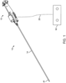
- Figure 1 illustrates an embodiment of a treatment system 10 used to remove debris, such as kidney stones.
- the system 10 includes a handle mechanism 12 from which a catheter 14 extends.
- the system 10 includes a handle mechanism 12 from which a catheter 14 extends.
- the handle 12 can be configured to provide, for example, a single trigger design comprising, or consisting of, two modes: an active irrigation mode only (i.e., active irrigation on/vacuum off) and an active irrigation mode in combination with a vacuum mode (i.e., active irrigation on/vacuum on).
- the handle 12 can be configured to provide, for example, a single trigger design comprising, or consisting of, three modes: passive irrigation on/active irrigation off/vacuum off; passive irrigation on/active irrigation on/vacuum off; passive irrigation on/active irrigation on/vacuum on. In an embodiment, there may be a minimum, passive amount of negative pressure even in the modes where the vacuum is off.
- Some aspects of the flow design allow for an uninterrupted conduit between the end of the device and the vacuum source such that there is high flow when vacuum is activated and minimal or no flow when vacuum is not activated.
- the catheter 14 can include various ports and lumens, including a vacuum lumen and an irrigation lumen running along the length of the catheter 14.
- the system 10 can also include a camera (digital visualization and lighting, e.g., video chip and LED) positioned at an end, distal face or a distal portion of the catheter 14 for providing real time imaging to the physician.
- a distal assembly 16 is at the distal end of the catheter 14 for irrigation and removal of the debris, with the assistance of the negative pressure applied through the vacuum lumen.
- the handle mechanism 12 allows the physician to hold and operate the system 10.
- the handle mechanism 12 can include features that allow a physical to operate various functions of the system, including the camera, vacuum pressure, the amount of irrigation and irrigation pressure, and the maneuverability of the catheter 14.
- the handle mechanism 12 can include mechanical and electronic controls that allow the physician to adjust the amount of negative pressure, regulate the discharge of the irrigation fluid, and steer the catheter through tortuous anatomical passageways via the use of wheels and/or levers attached to cables, as is well known in the art.
- the system 10 can be coupled to a control unit 18 via a connector 20.
- the control unit 18 can control or assist in controlling aspects of the operation of the system 10.
- the control unit 18 can control or assist in controlling visualization aspects of the system 10.
- the connector 20 can be a wired connection and/or a wireless connection.
- FIG. 2 shows the handle mechanism 12 for effecting kidney stone removal according to an embodiment.
- a finger grip portion 22 runs a portion of a length of the mechanism 12.
- An optional ledge portion 24 sits over where a user's hand would be while gripping the mechanism 12.
- Above the optional ledge portion 24 is a trigger 26, which is a part of a trigger mechanism to be described later.
- the trigger mechanism controls vacuum (or suction) and air flow, as well as irrigation operation of the mechanism 12.
- a user may operate the trigger 26 with one of their fingers.
- a distal tip steering control 28 sits at a proximal end portion of the mechanism 12.
- a user's thumb may control the positioning and/or steering of the distal tip of a catheter by manipulating a lever 30.
- FIG. 2 also shows a vacuum/suction port 32 and an irrigation port 34, as well as a catheter strain relief 36.
- a stone catcher receptacle 38 receives extracted kidney stones and/or fragments through a port 40.
- An access or working channel port 42 permits access to the catheter (not shown) to allow introduction of therapeutic tools such as lasers to the distal end of the catheter.
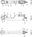
- FIG. 3 shows a rear view of the handle mechanism 12.
- the vacuum port 32, irrigation port 34, and catheter strain relief 36 are visible, as are the stone catcher receptacle 38 and distal tip steering control 28.
- FIG. 4 shows a side view of the mechanism 12. In FIG. 4 , many of the same elements are visible as in FIG. 2 .
- the vacuum port 32, irrigation port 34, and catheter strain relief 36 sit at the bottom of the mechanism 12, behind the stone catcher receptacle 38.
- the port 40 which deposits kidney stones, or fragments or portions of kidney stones, into the stone catcher receptacle 38, also is visible.
- FIG. 3 shows a rear view of the handle mechanism 12.
- the vacuum port 32, irrigation port 34, and catheter strain relief 36 are visible, as are the stone catcher receptacle 38 and distal tip steering control 28.
- FIG. 4 shows a side view of the
- FIG. 5 which is a front view of the mechanism 12, many of the same elements are visible as in FIG. 2 .
- the catheter strain relief 36 sits at the bottom of the mechanism 12, behind the stone catcher receptacle 38.
- the port 40 which deposits kidney stones or portions of kidney stones into the stone catcher receptacle 38, also is visible.
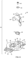
- FIG. 6 is an exploded view of a portion at the top of the mechanism 12. Collectively, the parts in FIG. 6 constitute a trigger mechanism assembly 44. Going from top to bottom in FIG. 6 , a screw or bolt 46 passes through a washer 48 and opening 50 of a trigger mechanism 52. The trigger mechanism 52 includes protrusions 54, 56, and 58. The function of these protrusions during actuation of the trigger mechanism 52 will be described in more detail below with respect to FIGS. 7-9 . The screw or bolt 46 also passes through a spring 60 or other resilient device and is received by a screw/bolt receptacle 62. In some examples, the bolt 46 holds the trigger securely to a base plate boss that captures the spring 60.
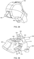
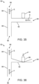
- FIGS. 35 and 36 show schematic diagrams of a vacuum/suction control system and method 82.
- a suction outlet tube 84 includes a suction opening 86, which is connected to a vacuum/suction source (not pictured). Flow through the suction outlet tube 84 is in the direction of arrow S.
- a suction target tube 88 includes a target opening 90, which is connected to a portion of the device that is in proximity of an area targeted for suction/vacuum.
- FIG. 36 shows a configuration in which flow through suction target tube 88 is in the direction of arrow T.
- An activation tube 92 includes an activation opening 94, which is open to ambient air.
- An activation pinch mechanism 96 is positioned adjacent to the activation tube 92 and is movable in the direction of arrow P from first position that allows flow in the direction of arrow B through the activation tube 92 (shown in FIG. 35 ) and a second position that prevents flow from activation opening 94 through activation tube 92 (shown in FIG. 36 ).
- the system and method 82 shows that the activation pinch mechanism 96 allows for control over the vacuum/suction flow.
- the vacuum source (not pictured) can be set to a provide a constant amount of suction (e.g., 200 mmHg) and the activation pinch mechanism 96 provides for on/off control over the vacuum/suction by opening or closing the activation tube 92. In the configuration shown in FIG.
- the activation pinch mechanism 96 is positioned such that air flows through the activation tube 92 in the direction of arrow B, through the suction outlet tube 84 in the direction of arrow S, and out to the vacuum/suction source.
- little or no flow is through the suction target tube 88 from the targeted area to the suction outlet tube 84.
- the activation pinch mechanism 96 is positioned such that no air flows through the activation tube 92. In the configuration shown in FIG.
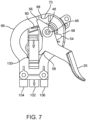
- FIGS. 7-9 show successive positions of the trigger 26.
- the trigger 26 is in the undepressed position. With the trigger 26 in that position, the vacuum and irrigation in the handle mechanism 12 are turned off.
- an irrigation bypass structure may allow for a minimum amount of irrigation to flow even when trigger 26 is in the undepressed position.
- the protrusion 54 pinches off an irrigation tube 98.
- the protrusion 56 is not in contact with the detent 68.
- the protrusion 58 may contact, but does not compress, a vacuum activation tube 100 (see also, for example, the activation tube 92 of Figures 35 and 35 ).
- the vacuum activation tube 100 is open to ambient air at one end and connected at an end 102 with vacuum tubing running from a vacuum source to a vacuum lumen running to the vacuum target area.
- the spring 60 or other resilient device engages the trigger mechanism 52 resiliently so that, when the user releases the trigger 26, the trigger 26 returns to its initial position, so that irrigation and vacuum are turned off. In some embodiments, irrigation is partially on at a minimum level and vacuum is off when the trigger 26 returns to its initial position.
- the trigger 26 is partly depressed, up to the point that the protrusion 56 contacts detent 68 in the mechanism body 66, indicating to the user that a first stopping point in operation has been reached.
- the protrusion 54 partly disengages with the irrigation tube 98, opening the irrigation tube 98 slightly, and allowing for some irrigation (or, in some embodiments, full irrigation flow).
- the protrusion 58 partly closes off the vacuum activation tube 100, but air still can flow through the vacuum activation tube 100, so vacuum at the target area still is off.
- the trigger 26 is fully depressed.
- the protrusion 56 proceeds past the detent 68 and seats up against the detent 70. In this position, the protrusion 58 pinches off the vacuum activation tube 100, thereby turning the vacuum on at the target area.
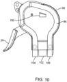
- FIG. 10 shows a view of the mechanism body 66 from an opposite side to those shown in FIGS. 7-9 .
- the irrigation tube 98 has an inlet 104 and an outlet 106.
- the activation tube 100 runs through the mechanism body 66.
- the trigger 26 has protrusions (not shown) which interact with the irrigation tube 98 and the activation tube 100 according to a degree of depression of the trigger 26.
- the function of the inlet 104 and the outlet 106 can be reversed, so that element 104 operates as an irrigation outlet, and element 106 operates as an irrigation inlet.
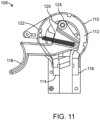
- FIG. 11 shows a portion of a kidney stone removal mechanism 108 according to an embodiment.
- a mechanism casing or body 110 contains an irrigation tube 112 with an irrigation inlet 114 and an irrigation outlet 116.
- a trigger 118 has a protrusion 120 which interacts with the irrigation tube 112. When the trigger 118 is undepressed, as shown in FIG. 11 , the protrusion 120 closes off, or at least constricts, the irrigation tube 112.
- a spring 122 or other resilient device moves against the force of a user depression of trigger 118 to return the trigger 118 to its undepressed state when the user releases the trigger 118.
- the trigger 118 rotates around a pivot point 124, causing the protrusion 120 to move away from the irrigation tube 112 to open the tube and enable irrigation.
- FIG. 11 shows a portion of a kidney stone removal mechanism 108 according to an embodiment.
- a mechanism casing or body 110 contains an irrigation tube 112 with an irrigation inlet 114 and an irrigation outlet 116.
- a trigger 118 has a
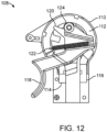
- FIG. 12 shows structure similar to that in FIG. 11 , except that in FIG. 12 , the trigger 118 is depressed, so that the protrusion 120 moves away from the irrigation tube 112 to open it up.
- FIG. 13 shows structure similar to that in FIG. 11 , but from an opposite side of the mechanism body 110. The trigger 118 is in the same position in FIG. 13 as in FIG. 11 . When the trigger 118 is in this position, a vacuum tube (not shown) in position 126 will not be pinched, so that vacuum or suction will be off. Comparing FIG. 13 with FIG. 11 , when vacuum or suction is off, so is irrigation.
- FIG. 14 shows structure similar to that in FIG. 13 , except that in FIG.
- the trigger 118 is depressed, so that the vacuum tube (not shown) in position 126 will be pinched, so that vacuum or suction will be on. Comparing FIG. 14 with FIG. 12 , when vacuum or suction is on, so is irrigation, similarly to other described embodiments.
- FIGS. 11 to 14 do not show an intermediate depression position for the trigger 118.
- kidney stone removal mechanism 108 enables a range of depression positions for trigger 118.
- there is an intermediate depression for the trigger 118 whereby the irrigation tube 112 will be slightly un-pinched, allowing irrigation to flow, while the vacuum tube (not shown) will be slightly pinched, so that vacuum or suction still will be off.
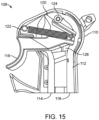
- FIG. 15 is a photograph of a portion of the kidney stone removal mechanism 108, similar to the structure in FIG. 11 , according to an embodiment.
- the mechanism body 110 contains the irrigation tube 112 with the irrigation inlet 114 and the irrigation outlet 116.
- the trigger 118 has the protrusion 120 which interacts with the irrigation tube 112. When the trigger 118 is undepressed, as shown in FIG. 15 , the protrusion 120 closes off, or at least constricts, the irrigation tube 112.
- the spring 122 or other resilient device moves against the force of a user depression of the trigger 118 to return the trigger 118 to its undepressed state when the user releases the trigger 118.
- the trigger 118 When depressed, the trigger 118 rotates around the pivot point 124, causing the protrusion 120 to move away from the irrigation tube 112 to open up the tube and enable irrigation.
- the trigger 118 is in the same position in FIG. 15 as in FIG. 13 .
- a vacuum tube (not shown) in position 126 will not be pinched, so that vacuum or suction will be off.
- vacuum or suction When vacuum or suction is off, so is irrigation.
- the function of the inlet 114 and the outlet 116 can be reversed, so that element 114 operates as an irrigation outlet, and element 116 operates as an irrigation inlet.
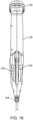
- FIGS. 16-22 show a kidney stone removal mechanism 128 according to an embodiment.
- a finger grip portion runs a portion of the length of mechanism.
- a trigger mechanism 130 is located at a proximal end of the kidney stone removal mechanism 128.
- a distal tip steering mechanism 132 also located at a proximal end of the kidney stone removal mechanism 128, enables manipulation of a catheter, particularly a distal end of a catheter, to position the distal end as desired for kidney stone fracture and/or removal.
- the catheter is connected to catheter strain relief 134.
- a stone catcher receptacle 136 receives removed kidney stones and/or pieces thereof.
- a working channel port 138 permits access to the catheter for insertion of devices and tools.
- FIG. 16 shows a front view of the kidney stone removal mechanism 128, there is a more detailed view of the catheter strain relief 134. There also is a front view of the stone catcher receptacle 136.
- the access or working channel port 138 permits access to a catheter to allow introduction of therapeutic tools such as lasers to the distal end of the catheter.
- FIG. 16 also shows a front view of the trigger 130, and a side view of the distal tip steering mechanism 132.
- FIG. 17 shows a side view of the kidney stone removal mechanism 128.
- a vacuum outlet 140 and irrigation inlet 142 are visible, as well as the catheter strain relief 134, the stone catcher receptacle 136, and a finger grip 143.
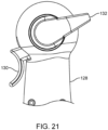
- FIGS. 19-21 show close ups of successive positions of the trigger 130 of the kidney stone removal mechanism 132, from undepressed in FIG. 19 to fully depressed in FIG. 21 .
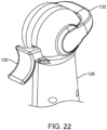
- FIG. 22 shows a perspective side view of FIGS. 19-21 .
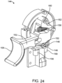
- FIG. 23 shows an exploded view of a trigger mechanism assembly 144 according to an embodiment.
- a bolt 146 and a washer 148 pass through a slot 150 in a trigger mechanism 152.
- An irrigation tube 154 has an irrigation inlet and irrigation outlet 166 and 168.
- a spring 156 biases a trigger 158 toward an undepressed position.
- a pivot 160 receives the trigger mechanism 152 by fitting through a hole 162 in the trigger mechanism 152. When a user actuates the trigger 158, the trigger mechanism 152 rotates around the pivot 160.
- An opening 164 leads to a vacuum outlet (not shown).
- FIG. 24 shows an assembled version of the trigger mechanism of FIG. 23 . Elements discussed above with respect to FIG. 23 are depicted with the same reference numerals in FIG. 24 .
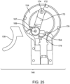
- FIGS. 25-27 show successive positions of the trigger 158 for the trigger mechanism 144, from undepressed in FIG. 25 to fully depressed in FIG. 27 , with corresponding movement of relevant parts.
- the trigger 158 is in its normal position, resulting from bias that the spring 156 or other resilient device (shown in previous Figures) applies.
- a roller 167 is mounted on a pin 169, at one end of a bar or lever 170.
- At the other end 172 of the bar or lever 170 is a mount 174 to which the bar or lever 170 is attached. With this structure, the bar or lever 170 pivots around the mount 174 when trigger 158 is depressed. Also in FIG.
- FIG. 25 the roller 167 is positioned away from the opening 164, which leads to a vacuum outlet (not shown).
- the roller 167 depresses the irrigation tube 154, closing off irrigation. Accordingly, in the trigger position shown in FIG. 25 , both irrigation and vacuum are turned off.
- Figure 25 further illustrates protrusions 176 and 178, the function of which is described with reference to FIGS. 26 and 27 .
- FIG. 26 shows an intermediate position of the trigger 158, with a correspondingly intermediate position of the roller 167, closer to the opening 164. Depression of the trigger 158 causes the bar or lever 170 to rotate around the mount 174. Depression of the trigger 158 to the extent shown in FIG.
- FIG. 26 causes the roller 167 to come into contact with the protrusion 178, providing more resistance and signaling to the user that the trigger 158 is in an intermediate position. In this position, the roller 167 exerts less pressure on irrigation tube 154. Accordingly, in the trigger position shown in FIG. 26 , vacuum still is turned off, but irrigation begins to be turned on.
- FIG. 27 shows a fully depressed position of the trigger 158. In this position, the user depressing the trigger 158 has caused the roller 167 to proceed over protrusion 178, to cover the opening 164, and to move farther away from the irrigation tube 154. The roller 167 moves up against the protrusion 176, signifying to the user that the trigger 158 is fully depressed. In this position, both vacuum and irrigation are turned on, so that kidney stones and/or pieces of kidney stones can be removed.
- FIG. 28 shows a mechanism 180 for kidney stone removal according to an embodiment.
- a user may employ a distal tip steering control 182 to position and/or steer a catheter 184 to perform appropriate operations to break up and/or remove kidney stones.
- One or more pull wires can facilitate positioning and/or steering of the catheter 184.
- User control of the trigger 186 controls operation of the trigger mechanism, described further herein, to control vacuum and irrigation through the catheter 184.
- a handle portion 188 is sized for a user to hold the mechanism 180, with the user's thumb operating the distal tip steering control 182 and one of the user's fingers operating the trigger 186.
- a user's thumb may operate the trigger 186, and a user's finger may operate the distal tip steering control 182.
- a port 190 connects to a vacuum source (not shown).
- the catheter 184 is attached to a catheter strain relief 192.
- a port 194 provides access to a working channel within the catheter 184 to facilitate introduction of therapeutic tools, such as a laser, to the distal end of the catheter 184.
- FIG. 29 shows an enlarged view of the distal tip steering control 182 and the trigger 186, and an upper portion of the handle portion 188.
- FIG. 30 shows an example of a trigger mechanism that may be used in the embodiment of FIGS. 28 and 29 .
- An irrigation tube 196 has inlet 198, connected to an irrigation source, and an outlet 200, connected to a distal tip (not shown) to irrigate a desired region.
- Posts 202 are located and sized to hold the distal tip steering control 182, which may be attached to the posts 202 via one or more pins (also not shown) passing through holes 204 in the posts 202.
- pull wires may be provided to guide movement and position of the catheter's distal tip to perform suitable actions to maneuver the tip into proper position for a kidney stone removal procedure.
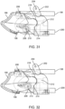
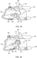
- FIGS. 31-34 show progressive depressions of the trigger 186.
- posts 202 remain in the same position, that is, the distal tip steering control 182 is not being operated.
- FIG. 31 shows the trigger 186 in an undepressed position. In this position, the roller 208 closes off, or at least constricts, irrigation the tube 196, while the port 212 is open. The roller 208 is set apart from a contact edge 214. This position corresponds to the vacuum and the irrigation both being turned off.
- initial depression of the trigger 186 causes the trigger 186 to rotate slightly to the right around the pivot pin 206, causing the roller 208 to move slightly upward and to the right.
- the irrigation tube 196 is opened further, allowing irrigation of the area to be treated.
- This positioning of the trigger 186 corresponds to an irrigation only state, with vacuum still turned off by virtue of the port 212 remaining open.
- further depression of the trigger 186 causes the trigger 186 to rotate slightly more to the right around the pivot pin 206, causing the roller 208 to move slightly more upward and to the right.
- the port 212 remains open, so vacuum still is turned off.
- the irrigation tube 196 is squeezed less, allowing for more irrigation of the affected area.
- the roller 208 contacts an edge 214, which acts as a detent, according to an embodiment.
- the roller 208 When the roller 208 contacts the edge 214, the user is alerted, by virtue of encountering resistance to depression of the trigger 186.
- FIG. 34 when the user overcomes the resistance at the edge 214 and depresses the trigger 186 farther, the trigger 186 rotates farther upward and to the right until the roller 208 covers the port 212. At this point, the roller 208 is seated in indentation 216, and cannot move farther. In this fashion, the user is aware that the trigger depression is at maximum.
- irrigation remains on, and vacuum turns on, by virtue of the port 212 being closed (for example, performing as described in FIGS. 35 and 36 ).
- irrigation fluid can flow along flow path FP from the inlet 232 through the mechanism head 222 and to the outlet 236. Some minor amount of irrigation fluid may still flow through the bypass structure 220, but most of the irrigation fluid flows through the mechanism head 22.
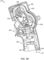
- FIG. 39 shows the irrigation bypass structure 220 having an inlet tube 238 that defines an inlet lumen 240, which connects the inlet 232 with the supply outlet 236 and having an outlet tube 242 that defines an outlet lumen 244, which connects a return inlet 246 with the outlet 236.
- An irrigation tube (not pictured) connects the supply outlet 236 with return the inlet 246 and carries irrigation fluid through the mechanism head and trigger activation mechanism of various embodiments disclosed herein.
- the inlet tube 238 is connected with the outlet tube 242 by a bypass 250, which includes a pair of bypass tubes 252 connected by a bypass connector 254.
- FIG. 39 shows the bypass tubes 252 as hose barbs and the bypass connector 254 as tubing, but other equivalent configurations of similar structure can be used.
- the bypass 250 includes flow restrictions 256, which are narrow lumens (narrower than the diameter of the inlet lumen 240) that restrict the amount of irrigation fluid that can flow through the bypass 250.
- FIG. 39 shows two flow restrictions 256 because it may be desirable for manufacturing efficiency to produce two of the same parts and connect them via the connector 254 to form irrigation bypass structure 220, but a single flow restriction 256 can be sufficient to provide the function of the irrigation bypass structure 220 as disclosed herein.
- the inner diameter of the flow restriction 256 can be in the range of about 5% to about 30% of the inner diameter of the inlet lumen 240 and in some embodiments about 20% of the inner diameter of inlet 240.
- the first bypass fitting 270 and the second bypass fitting 272 connect via complementary features and form a fluid tight seal via O-ring 274.
- the first bypass fitting 270 and the second bypass fitting 272 form a conduit for fluid bypass, and this conduit include a flow restriction 276 that has a lumen narrower than the inlet lumen 262.
- the irrigation bypass structure 258 functions to provide a well-defined minimum irrigation flow rate when the irrigation tube in the mechanism head is closed by the trigger mechanism.
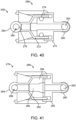
- FIG. 41 shows an irrigation bypass structure 278 of another alternate embodiment viewed in cross section defined by a plane along line C in the embodiment of similar irrigation bypass structures 220 and 258.
- This bypass structure can be implemented with any of the embodiments disclosed above.
- the irrigation bypass structure 278 includes an inlet tube 280, which defines an inlet lumen 282, and an outlet tube 284, which defines the outlet lumen 286. These lumens are connected by an irrigation tube (not pictured) that carries irrigation fluid through mechanism heads and trigger activation systems disclosed herein.
- FIG. 41 shows that the inlet lumen 282 and the outlet lumen 286 are also connected by a bypass 288, which is formed by a first bypass fitting 290 and a second bypass fitting 292.
- the first bypass fitting 290 and the second bypass fitting 292 connect via complementary features and form a fluid tight seal via compressible member 294, which is formed of a resiliently flexible material and includes an interior flow restriction 296.
- the compressible member 294 is similar to an O-ring or grommet in shape or function in that it provides a fluid tight seal, but it also provides a lumen in the form of the flow restriction 296, which takes a predefined diameter when the first bypass fitting 290 and the second bypass fitting 292 are connected. This predefined diameter of flow restriction 6664 is narrower than the diameter of the inlet lumen 282.
- the irrigation bypass structure 278 functions to provide a well-defined minimum irrigation flow rate when the irrigation tube in the mechanism head is closed by the trigger mechanism.
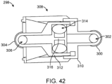
- FIG. 42 shows an irrigation bypass structure 298 of another alternate embodiment viewed in cross section defined by a plane along line C in the embodiment of similar irrigation bypass structures 220, 258, and 278.
- This bypass structure can be implemented with any of the embodiments disclosed above.
- the irrigation bypass structure 298 includes an inlet tube 300, which defines inlet lumen 302, and an outlet tube 304, which defines outlet lumen 306. These lumens are connected by an irrigation tube (not pictured) that carries irrigation fluid through mechanism heads and trigger activation systems disclosed herein.
- FIG. 42 shows that the inlet lumen 302 and the outlet lumen 306 are also connected by a bypass 308, which is formed by a first bypass fitting 310 and a second bypass fitting 312.
- the first bypass fitting 310 and the second bypass fitting 312 connect via complementary features and form a fluid tight seal via O-ring 314, which is formed of a resiliently flexible material.
- the second bypass fitting 312 also includes an interior flow restriction 316, which has a diameter narrower than the diameter of the inlet lumen 300.
- irrigation bypass structure 298 functions to provide a well-defined minimum irrigation flow rate when the irrigation tube in the mechanism head is closed by the trigger mechanism.
- the various flow control mechanisms and bypass structures described herein can alternatively reside in a separate unit from the handle of the device.
- a flexible irrigation tube and a flexible vacuum line connect the separate unit with the handle.
- the separate unit can be controlled by the user via foot pedals, a touchscreen, or other similar activation mechanisms.
- the mechanisms in the separate unit can be controlled mechanically, electro-mechanically, electromagnetically, or by other similar control methods.
- the separate unit is a reusable unit, similar to or included with the control unit 18.
- control unit 18 provides irrigation fluid and negative pressure to the system in addition to imaging control.
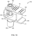
- FIG. 43 shows the mechanism 12 for effecting kidney stone removal according to an embodiment.
- the lower portion of the mechanism includes the stone catcher receptacle 38 in fluid communication with the vacuum inlet 32.
- FIG. 44 is a rotated and enlarged view of the mechanism 12 inside box W of FIG. 43 and shows the location on mechanism 12 of a flow indicator 318.
- the flow indicator 318 provides a visual (and optionally audible) indication of whether air and/or fluid is flowing through mechanism 12 and out to the vacuum inlet 32.
- the absence of fluid flow through mechanism 12 can indicate that there is a clog somewhere in the fluid path within the stone removal device.
- the clog could be in the catheter section or in the mechanism 12, and it can be important to address such a clog to prevent overpressure in the kidney caused by continuing to irrigate the kidney in the presence of a clog.
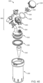
- FIG. 45 is an exploded view of a stone catcher assembly 320 that is configured to be part of mechanism 12 and can be implemented with any of the above-described embodiments.
- a flow indicator 322 is contained within a flow indicator housing 324 with an O-ring 326 that seals the flow indicator housing 324 with a flow indicator cover 328, which is transparent or translucent such that a user can observe the movement of the flow indicator 322.
- An axle 330 allows the flow indicator 322 to rotate in the presence of flow. Alternate configurations of flow indicators are within the scope of this disclosure, such as any configuration that moves visibly in response to flow within a housing.
- the flow indicator housing 324 is connected to a stone catcher receptacle cap assembly 332 by a fluid tight seal, such as with an O-ring 334.
- the stone catcher receptacle cap assembly 332 is connected with a stone catcher receptacle 336 via a stone catcher receptacle seal 338.
- the stone catcher receptacle cap assembly 332 is also connected with an inflow assembly 340.
- inflow assembly 340 In use, the direction of flow of fluid (including kidney stone debris) in the stone catcher assembly 320 is through inflow assembly 340, which is connected to the catheter section of the stone removal device, and to the stone catcher receptacle 336. Fluid and air are drawn up through stone catcher receptacle filter 342, which keeps debris within the stone catcher receptacle 336, but allows fluid and air to pass through and eventually into the flow indicator housing 324 to interact with the flow indicator 322.
- the flow indicator 322 is unlikely to become jammed or stuck with kidney stone debris.
- the flow indicator should be protected from having its movement stopped by debris interacting with the flow indicator itself.
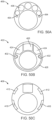
- FIG. 46 and 47 are two views of the flow indicator mechanism that includes the flow indicator 322 positioned in the flow indicator housing 324.
- Fluid from the stone catcher receptacle 336 enters the flow indicator housing 324 via a flow inlet 344, which is connected with an indicator inlet 346 to introduce fluid into the flow indicator housing 324 to interact with the flow indicator 322.
- the flow indicator 322 includes at least two flow indicator vanes 352 that interact with fluid as it moves from the indicator inlet 346 to the indicator outlet 348.
- the movement of fluid between the indicator inlet 346 to the indicator outlet 348 pushes on the flow indicator vanes 352 and creates movement of the flow indicator 322 by causing it to rotate around the axle 330.
- the indicator inlet 346 and the indicator outlet 348 can be positioned and various places in the flow indicator housing 324 such that the fluid flow interacts with more than one flow indicator vane 352 on the path between the indicator inlet 346 to the indicator outlet 350.
- the flow indicator embodiments disclosed herein are one approach to preventing overpressure in the device and/or in the anatomy during a kidney stone removal procedure.
- mechanisms and devices disclosed herein may include a pressure relief valve capable of relieving fluid pressure when the fluid pressure exceeds a certain predetermined safety threshold.
- a pressure relief valve may be included on the mechanism handle, on the catheter, at the junction between the handle and the catheter, on the fluid supply line, and/or at the junction of the fluid supply line and handle.
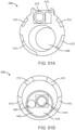
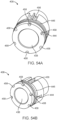
- FIG. 48A and FIG 48B each show a perspective view of a distal assembly 400, which is part of the distal section of the insertable treatment system 10.
- FIG. 48B illustrates a view of the distal assembly 400 with the outer member 402 retracted as compared to FIG. 48A .
- the outer member 402 can be one or more layers of a tubular structure, and one or more of the layers of the tubular structure can be part of the outer portion of proximal sections of the catheter's shaft.
- the layers of the outer member 402 can include a comparatively softer and more flexible outer layer over a comparatively stiffer inner layer.
- the distal assembly 400 comprises a vacuum lumen 404 defined by a vacuum shaft 406.
- the distal end of the vacuum shaft 406 terminates at or near the distal end of a nozzle tip 408.
- the nozzle tip 408 includes one or more irrigation ports 410 and 412.
- the irrigation ports 410 and 412 have a slotted shape and can direct irrigation fluid forward and laterally from the distal end of the nozzle tip 408.
- the distal assembly further comprises an image sensor 414 and a light source 416 on either side of the image sensor 414.
- the image sensor 414 can be a semiconductor chip designed for image capture and the light source 416 can be a light emitting diode or similar light source.
- FIG. 48B illustrates a printed circuit board 418 connected with the image sensor 414 and the light source(s) 416.
- the region around the printed circuit board 418 can also be filled with potting material.
- FIG. 48B also illustrates the distal end of a pull wire 420 that can be used to steer the distal assembly 16 of the insertable treatment system 10.
- the nozzle tip 408 includes a recess into which a ferrule or similar fitting on the end of the pull wire 420 can be inserted to provide a distal attachment point for the pull wire 420.
- FIG. 49A illustrates a perspective view of multiple parts of the distal assembly 400 and FIG. 49B illustrates a perspective, exploded view of the parts of FIG. 49A .
- the nozzle tip 408 is configured to accept a distal manifold 422 in the interior of the nozzle tip 408.
- the distal manifold 422 includes conduits 424, although other examples of the distal manifold 422 can include more or fewer total conduits.
- the conduits 424 function to direct irrigation fluid to the irrigation ports 410 and 412.
- the distal manifold 422 also includes an upper recess 426 for accommodating the imaging assembly (or components thereof), including, but not limited to, the at least one printed circuit board 418, the at least one light source 416, and the at least one image sensor 414.
- the distal manifold 422 also includes a proximal flange 428 that provides a structural member to join and seal against the nozzle tip 408 on one side and a shaft manifold 430 on the other side. The seals on either side of the proximal flange 428 can be fluid tight.
- the distal manifold 422 also includes pull wire recesses 432 for attaching the steering pull wires to the distal assembly 16 to facilitate steering of the insertable treatment system 10.
- FIG. 49B illustrates that the shaft manifold 430 includes pull wire lumens 434 and multiple irrigation lumens 436 (only one of the five irrigation lumens 436 illustrated in FIG. 49B is labeled).
- the shaft manifold 430 can extend the entire length of the catheter's 14 shaft or only a portion of length of the catheter's 14 shaft. In some examples of the catheter 14, there is no shaft manifold and the lumen defined by the outer member 402 serves as an irrigation lumen and as a path for steering mechanisms such as pull wires.
- FIG. 50A, FIG. 50B, and FIG. 50C illustrate end views of the parts of the distal assembly 400.
- FIG. 50A illustrates the shaft manifold 430 with two pull wire lumens 434 and multiple irrigation lumens 436 (only one of the five irrigation lumens 436 illustrated in FIG. 4A is labeled).
- FIG. 50B illustrates the distal manifold 422 with conduits 424, the upper recess 426, the proximal flange 428, and the pull wire recesses 432.
- FIG. 50C illustrates the nozzle tip 408 with irrigation ports 410 and 412.
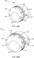
- FIG. 51A and FIG. 51B illustrate two different examples of the nozzle tip 408.
- FIG. 51A illustrates an example of the nozzle tip 408 in which the image sensor 414 and light source 416 are mounted on the nozzle tip 408 and multiple irrigation ports 410 and 412 are present. This example is conceptually similar to the examples illustrated in previous figures.
- the nozzle tip 408 includes a nozzle lumen 438 that, in some examples, can accommodate the vacuum shaft 406 and, in alternate examples, can define the vacuum lumen 404.
- the elongate insertable member 440 includes a working lumen 442 through which therapeutic or diagnostic devices can be slid with respect to the elongate insertable member 440.
- therapeutic or diagnostic devices include, but are not limited to, lasers, sensors, and graspers.
- the working lumen 442 can allow for the aspiration of fluid and kidney stone fragments while the elongate insertable member 440 is in place.
- the insertable elongate member 440 can have an outer diameter of from about 1 mm to about 4 mm and the working lumen 442 can have an inner diameter of from about 0.3 mm to about 1.5 mm.
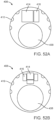
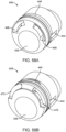
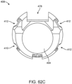
- FIG. 52A and FIG. 52B illustrate alternative examples of the nozzle tip 408.
- the nozzle tip 408 includes a single image sensor 414 and a single light source 416 while in FIG. 52B the nozzle tip 408 includes a single image sensor 414 and three light sources 416 (only one light source 416 is labeled).
- the arrangement of light sources 416 in FIG. 52B may be preferable in some examples as the arrangement may provide more uniform illumination due to the placement of light sources 416 on either side of the image sensor 414.
- FIG. 52A and FIG. 52B each illustrate six irrigation ports 410 (only one irrigation port 410 is labeled). These irrigation ports 410 are configured to direct fluid distally and laterally from the nozzle tip 408.
- the nozzle tip 408 includes a nozzle lumen 438 that, in some examples, can accommodate the vacuum shaft 406 and, in alternate examples, can define the vacuum lumen 404.
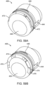
- FIG. 53A and FIG. 53B illustrate alternative examples of the nozzle tip 408.
- the nozzle tip 408 includes the nozzle lumen 438 that, in some examples, can accommodate the vacuum shaft 406 and, in alternate examples, can define the vacuum lumen 404.
- the nozzle tip 408 also includes at least one pull wire recess 444.
- the nozzle tip 408 includes a tip manifold 446 that is configured to direct fluid to the irrigation ports.
- the tip manifold 446 is in fluid communication with one or more irrigation lumens that conduct irrigation fluid from the handle 12 and down the catheter 14 and provides a fluid path to each of the irrigation ports.
- FIG. 53A illustrates slot-shaped irrigation ports 448 and 450.
- the irrigation ports 448 are larger than the irrigation ports 450.
- the interior of each of the irrigation ports 448 and 450 is configured to direct fluid radially away from the central axis of the nozzle tip 408.
- FIG. 53B illustrates circle-shaped irrigation ports 452 and 454 and they are similarly sized.
- the irrigation ports 452 are on the front face of the nozzle tip 408.
- the openings of the irrigation ports 454 are on the front face and extend into the side, lateral wall of the nozzle tip 408.
- each of the irrigation ports 452 and 454 is configured to direct fluid radially away from the central axis of the nozzle tip 408.
- the configuration of the irrigation ports 454 allows the irrigation ports 454 to direct fluid more radially outward than the ports 452.
- the direction of fluid may approximate a spiral directed away from the central axis of the nozzle tip 408 in both the slot-shaped and circle-shaped examples.
- FIG. 54A and FIG. 54B illustrate alternative examples of the nozzle tip 408.
- the nozzle tip 408 includes the nozzle lumen 438 that, in some examples, can accommodate the vacuum shaft 406 and, in alternate examples, can define the vacuum lumen 404.
- the nozzle tip 408 also includes at least one pull wire recess 444.
- the nozzle tip 408 includes the tip manifold 446 that is configured to direct fluid to the irrigation ports.
- the tip manifold 446 is in fluid communication with one or more irrigation conduits 456 to provide a fluid path to each of the irrigation ports.
- the nozzle lumen 438 is concentric with the outer diameter of the nozzle tip 408. FIG.
- FIG. 54A illustrates six circle-shaped irrigation ports 458.
- the irrigation ports 458 can be elliptical-shaped, slot-shaped, or arc-shaped.
- the openings of the irrigation ports 458 extend from the front face into the side, lateral wall of the nozzle tip 408.
- FIG. 54B illustrates five circle-shaped irrigation ports 458 and they are similarly sized.
- the interior of each of the irrigation ports 458 is configured to direct fluid radially away from the central axis of the nozzle tip 408.
- the exit angle for the irrigation ports depicted in FIG. 54A and 54B is approximately 45 degrees with respect to the central axis of the nozzle tip 408 and the direction of the irrigation fluid away from the nozzle tip 408 is radially away from the central axis of the nozzle tip 408.
- FIG. 55A and FIG. 55B illustrate alternative examples of the nozzle tip 408.
- the nozzle tip 408 includes a nozzle lumen 438 that, in some examples, can accommodate the vacuum shaft 406 and, in alternate examples, can define the vacuum lumen 404.
- the nozzle lumen 438 is offset from the center of the nozzle tip 408.
- the nozzle tip 408 also includes at least one pull wire recess 444.
- the nozzle tip 408 includes the tip manifold 446 that is configured to direct fluid to the irrigation ports.
- the tip manifold 446 is in fluid communication with one or more irrigation lumens that conduct irrigation fluid from the handle 12 and down the catheter 14 and provides a fluid path to each of the irrigation ports.
- 55A illustrates three circle-shaped irrigation ports 458 with an exit angle of about 45 degrees and configured to direct fluid radially away from the central axis of the nozzle tip 408 and two elliptical irrigation ports 460 that direct fluid at a 45-degree angle down from the central axis of the nozzle tip 408 but not in a radially diverging direction.
- the openings of the elliptical irrigation ports 460 are on the front face of the nozzle tip 408.
- the openings of the circle-shaped irrigation ports 458 encompass both the front face and side lateral wall.
- 55B illustrates five circle-shaped irrigation ports 458 with an exit angle of about 45 degrees and configured to direct fluid radially away from the central axis of the nozzle tip 408 and two elliptical irrigation ports 460 that direct fluid at a 45-degree angle down from the central axis of the nozzle tip but not in a radially diverging direction.
- FIG. 56 illustrates a rear, perspective view of the nozzle tip 408 (e.g., can be any of the described nozzle tips) with a tip manifold 446 that provides a fluid path to various irrigation ports on the distal face of the nozzle tip 408.
- the nozzle tip 408 also includes a nozzle irrigation lumen 462 that provides a path for fluid from the catheter 14 to the tip manifold 446.
- FIG. 57 illustrates an alternative example of the nozzle tip 408.
- the nozzle tip 408 includes the nozzle lumen 438 that, in some examples, can accommodate the vacuum shaft 406 and, in alternate examples, can define the vacuum lumen 404.
- the nozzle lumen 438 is offset from the center of the nozzle tip 408.
- the nozzle tip 408 also includes at least one pull wire recess 444.
- the nozzle tip 408 includes the tip manifold 446 that is configured to direct fluid to the irrigation ports.
- the tip manifold 446 is in fluid communication with one or more irrigation lumens that conduct irrigation fluid from the handle 12 and down the catheter 14 and provides a fluid path to each of the irrigation ports.
- the nozzle tip 408 includes two elliptical irrigation ports 466 that direct fluid at a 45-degree angle down from the central axis of the nozzle tip but not in a radially diverging direction.
- FIG. 58A and FIG. 58B illustrate alternative examples of the nozzle tip 408.
- the nozzle tip 408 includes a nozzle lumen 438 that, in some examples, can accommodate the vacuum shaft 406 and, in alternate examples, can define the vacuum lumen 404.
- the nozzle lumen 438 is offset from the center of the nozzle tip 408.
- the nozzle tip 408 also includes at least one pull wire recess 444.
- the nozzle tip 408 includes the tip manifold 446 that is configured to direct fluid to the irrigation ports.
- the tip manifold 446 is in fluid communication with one or more irrigation lumens that conduct irrigation fluid from the handle 12 and down the catheter 14 and provides a fluid path to each of the irrigation ports.
- FIG. 58A illustrates two slotted irrigation ports 468, each with an exit angle of about 45 degrees and configured to direct fluid radially away from the central axis of the nozzle tip 468.
- Each irrigation port has an arc of about 70 degrees and are separated by a central region with an arc of about 40 degrees. Together, the irrigation ports 468 can provide a sweep of fluid of about 180 degrees.
- FIG. 58B illustrates two slotted irrigation ports 470, each with an exit angle of about 65 degrees and configured to direct fluid radially away from the central axis of the nozzle tip 408.
- Each irrigation port 470 has an arc of about 70 degrees and the irrigation ports 470 are separated by a central region with an arc of about 40 degrees. Together, the irrigation ports 470 can provide a sweep of fluid of about 180 degrees.
- FIG. 58A and 58B illustrate that the irrigation ports 468 and 470 are configured to direct fluid both distally and laterally from the distal face of the nozzle tip 408.
- FIG. 59A illustrates two slotted irrigation ports 472, each with an exit angle of about 45 degrees and configured to direct fluid radially away from the central axis of the nozzle tip 408.
- Each irrigation port 472 has an arc of about 70 degrees and the irrigation ports 472 are separated by a central region with an arc of about 40 degrees. Together, the irrigation ports 472 can provide a sweep of fluid of about 180 degrees.
- FIG. 59A illustrates that the irrigation ports 472 are configured to direct fluid both distally and laterally from the distal face of the nozzle tip 408.
- FIG. 59B illustrates four slotted irrigation ports 474 and 476, each with an exit angle of about 45 degrees and configured to direct fluid radially away from the central axis of the nozzle tip 408.
- Each irrigation port has an arc of about 20 degrees.
- Irrigation ports 474 are separated by a central region with an arc of about 50 degrees.
- Neighboring irrigation ports 474 and 476 are separated by a region with an arc of about 40 degrees. Together, the irrigation ports 474 and 476 can provide a sweep of fluid of about 180 degrees.
- FIG. 59A and FIG. 59B illustrate that the irrigation ports are configured to direct fluid both distally and laterally from the distal face of the nozzle tip 408.
- irrigation port configurations presented herein demonstrate that the nozzle tip can achieve various spray patterns by manipulating variables such as the size, shape, and number of irrigation ports, the exit angles of the irrigation ports, the placement of the irrigation ports on the distal face of the nozzle tip (i.e., entirely on the distal face or partially on the distal face and partially on the lateral portions of the nozzle tip as shown by the figures). Further, one or more of the irrigation ports may be configured the same as or different from the configuration of one or more of the irrigation ports on the same nozzle tip.
- FIG. 60 and FIG. 61 each are perspective views of an embodiment of the distal assembly 400, which is in the distal section of the insertable treatment system 10.
- Both FIG. 60 and FIG. 61 illustrate the outer member or an outer hypotube 402 included in the distal assembly 400.
- the outer member 402 of the distal assembly 400 can include one or more layers of a tubular structure.
- the outer hypotube 402 can be at least partially covered by a more flexible outer layer (not pictured).
- FIG. 60 and FIG. 61 illustrate the vacuum lumen 404 defined by the nozzle tip 408 in the distal assembly 400 and defined by a vacuum shaft (not pictured) in portions of the device proximal of the distal assembly 400.
- FIG. 60 and FIG. 61 includes an angled distal face to reduce the distal-most surface area of the nozzle tip 408, which can reduce the likelihood of trauma to tissue as the device is advanced distally.
- the edges of the distal face are radiused or smoothed with curvature as compared to a sharply angled corner for the same reason of reducing the likelihood of trauma.
- This angled distal face or edges being radiused and smoothed can be implemented with any of the nozzle tip 408 configurations disclosed above.
- the nozzle tip 408 is illustrated to include four irrigation ports arranged in two pairs - a pair of upper irrigation ports 412 and a pair of lower irrigation ports 410 - but in the perspective view of FIG. 60 and FIG. 61 only one of each pair is visible.
- the pairs of irrigation ports 410 and 412 have a slotted shape and can direct irrigation fluid forward and laterally from the distal end of the nozzle tip 150.
- the image sensor 414 is set on the nozzle tip 408 and the light source 416 can be on either side of the image sensor 414.
- the image sensor 414 can be a semiconductor chip designed for image capture and the light source 416 can be a light emitting diode or similar light source.
- the region around the image sensor 414 and the light source(s) 416 can be filled with the type of potting material commonly used with electronics, provided that the material is biocompatible or otherwise suitable for use with a medical device.
- FIG. 62A and FIG. 62B illustrate a perspective view and a side view, respectively, of an embodiment of the nozzle tip 408 of the distal assembly 400.
- the nozzle tip 408 includes the pair of upper irrigation ports 412 and the pair of lower irrigation ports 410 arranged around a vacuum lumen 404.
- the nozzle tip 408 includes an upper recess 478 that provides a place to mount an image sensor and light source.
- FIG. 62B illustrates the angled distal face of the nozzle tip 408.
- the nozzle tip 408 includes two conduits 480, one on each side of the nozzle tip 408, that provide a fluid path between the irrigation ports 410 and 412 and the irrigation lumen in the shaft section of the catheter.
- the nozzle tip 408 can include multiple conduits 480.
- each conduit 480 includes a divider 482 that helps direct fluid to each of the irrigation ports 410 and 412.
- divider 482 helps direct fluid to each of the irrigation ports 410 and 412.
- the dimensions of the divider influences the flow characteristics of the irrigation fluid at each irrigation port and can be varied to achieve the desired flow characteristics at each port.
- FIG. 62C illustrates an end view of a nozzle tip 408 and shows that the upper irrigation ports 412 and the lower irrigation ports 410 include front-facing openings.
- the interior of the irrigation ports 410 and 412 can be angled such that irrigation fluid exits the nozzle tip at a departure angle with respect to the central axis of the nozzle tip, as described herein.
- the irrigation ports 410 and 412 can be characterized by their shape, their radial distribution, their departure angle, and their front-facing area, among other parameters.
- the radial distribution of irrigation ports is such that the irrigation ports are substantially evenly distributed about the circumference of the nozzle.
- the largest angle between any two adjacent irrigation ports measured from center to center of each irrigation port is less than about 110 degrees and depends on the number of irrigation ports on the nozzle. With more than three irrigation ports, there can be a pair of adjacent irrigation ports for which the angle measured from center to center of each irrigation port substantially about 110 degrees and the several other irrigation ports have angles measured from center to center of each irrigation port that are substantially less than about 110 degrees.
- the irrigation ports have a main axis that is at an angle with respect to the central longitudinal axis of the nozzle.
- This angle or the nozzle exit angle can be in the range of from about 30 degrees to about 60 degrees and can be referred to as the irrigation port departure angle.
- Nozzles can be configured with irrigation ports having different departure angles or identical departure angles as other irrigation ports on the same nozzle. Sets of irrigation ports can have the same departure angle, and that angle can be different from another set of irrigation ports on the same nozzle. In some preferred examples, the irrigation port departure angle is about 45 degrees.
- the irrigation departure port angle is 30 degrees, 31 degrees, 32 degrees, 33 degrees, 34 degrees, 35 degrees, 36 degrees, 37 degrees, 38 degrees, 39 degrees, 40 degrees, 41 degrees, 42 degrees, 43 degrees, 44 degrees, 45 degrees, 46 degrees, 47 degrees, 48 degrees, 49 degrees, 50 degrees, 51 degrees, 52 degrees, 53 degrees, 54 degrees, 55 degrees, 56 degrees, 57 degrees, 58 degrees, 59 degrees, or 60 degrees.
- on one nozzle there is one set of irrigation ports that has a departure angle of 34 degrees and another set of irrigation ports that has a departure angle of 50 degrees. Table 1 shows the departure angles for pairs of irrigation ports for several different nozzle designs.
- nozzle tip designs To characterize preferred examples of nozzle tip designs, several nozzle tips were fabricated.
- the nozzle tips included two pairs of irrigation ports where the top and bottom (i.e., upper and lower) were symmetrical pairs having the same slotted shape and departure angle.
- Table 2 shows the relevant dimensions of several different nozzle designs. The area and perimeter of each individual port in a pair is shown in the table.
- Test samples were built with a representative vacuum lumen and camera wire to approximate the pressure drop and flow characteristics of a fully built device.
- Flow rate can be determined by measuring the mass of water exiting the nozzle as a function of time.
- the experimental setup included a conventional saline irrigation bag under a certain pressure (for example, 2 psi or 4 psi) connected with the catheter and nozzle sections of the device.
- Table 3 shows the results of flow rate testing in grams per second for several nozzle arrangements.
- the preferred minimum irrigation mass flow rate from a saline bag at 2 psi is about 0.55 g/s and the preferred minimum irrigation mass flow rate from a saline bag at 4 psi is about 0.75 g/s.
- each irrigation port contributes 1/N of the total mass flow rate, where N is the number of irrigation ports, and this fraction can be converted to a percentage.
- the various irrigation ports were measured as contributing between 15%-30% of the total irrigation mass flow rate as compared to the calculated amount of 25%.
- the irrigation mass flow rate is substantially similar from each of the irrigation ports.
- the irrigation mass flow can be between two and four times larger from some irrigation ports than from others. This asymmetry can be used advantageously to provide high irrigation mass flow in some directions from the nozzle.
- FIG. 63A illustrates a test apparatus 484 for determining affected area including a flat test surface 486 having a grid pattern onto which is spread a bed of kidney stone fragments 488 or simulated kidney stone fragments having a size range of from about 1.8 mm to 2.0 mm.
- a preferred test apparatus includes a bed of kidney stone fragments having substantially uniform sizes.
- the test apparatus includes a mount 490 for aligning the distal end of the device, including the nozzle 408, at a fixed distance above and parallel to the bed of kidney stones on the grid pattern.
- the nozzle is rotated 90 degrees such that the four test runs are able to approximate the three-dimensional volume affected by the irrigation port arrangement on the nozzle. Further, the distance of the nozzle above the grid surface can be changed to approximate a larger or smaller three-dimensional volume. In some preferred examples, the distance from the nozzle to the grid surface is about 6 mm. Table 4 shows the results of affected area testing in millimeters squared for several nozzle arrangements.
- Table 4 Affected area for certain nozzle designs Design Top (mm 2 ) Bottom (mm 2 ) Left (mm 2 ) Right (mm 2 ) K1 300 0 321 375 K2 274 0 383 0 K3 279 0 375 98 K4 675 0 466 633 K5 64 130 397 296 L1 0 239 143 208 L2 109 196 242 339 L3 426 50 432 434 L4 384 168 384 386
- Table 5 shows the results of closed environment testing such that the distances in the table reflect the maximum distance from which a nozzle design can cause motion in stone fragments in the test apparatus when irrigation fluid is supplied at 2 psi.
- Table 5 Fluidizing distance for certain nozzle designs Design Distance (mm) K1 19 K3 20 K4 22 K5 16 L1 24 L2 15 L3 22 L4 22
- Empirical testing of various nozzle configurations disclosure herein has demonstrated some preferred performance characteristics for the aspects of the method in which it is desirable to fluidize kidney stone fragments.
- the fluid velocity in some preferred examples is in the range of from about 0.50 m/s to about 1.50 m/s when the applied pressure is 2 psi and preferably is at least about 1.00 m/s.
- the fluid velocity in other preferred examples is in the range of from about 0.9 m/s to about 2.00 m/s when the applied pressure is 4 psi and preferably is at least about 1.45 m/s.
- FIG. 64 illustrates a cross-sectional view of a portion of a catheter 14.
- the outer member of the catheter 14 includes an outer jacket 492 and an outer hypotube 494.
- pull wires 496 positioned within pull wire hypotubes 498 such that the pull wires 496 are free to slide longitudinally with respect to the pull wire hypotubes 498.
- the pull wire hypotubes 498 can be fixed against the outer member and on opposite sides of the outer member.
- the pull wire hypotubes 498 are fixed only at the distal end of the catheter 14.
- An electrical cable 500 is also within the outer member and connects the image sensor in the distal assembly with the handle.
- the electrical cable 500 is free to move within the outer member but is fixed at or near its distal and proximal ends within the outer member.
- a vacuum shaft 502 that encompasses a vacuum lumen 504 is also within the outer member and connects the vacuum lumen 504 defined by the nozzle tip with the handle 12.
- the vacuum shaft 502 is also free to move within the outer member but is fixed at or near its distal and proximal ends within the outer member.
- the remaining space within the outer member that is not occupied by the pull wire hypotubes 498, the electrical cable 500, or the vacuum shaft 502 is the irrigation space 506 through which irrigation fluid can flow from the handle to the conduits in the distal assembly.
- the irrigation space 506 is not a fixed shape.
- One advantage of this arrangement is that there is no dedicated irrigation shaft, which decreases the number of structures within the catheter shaft assembly 14. Fewer structures results in ease of manufacture and increased flexibility in the catheter shaft assembly.
- the irrigation space may take the general shape of an annulus between the outer member and the vacuum shaft but when the catheter shaft is curved the irrigation space may take the general shape of a crescent as the vacuum shaft is pressed against the inner wall of the outer member.
- the above catheter advancements have provided the ability to combine the camera, laser, aspiration, and irrigation components into one system, to streamline kidney stone removal procedure and reduce the chances of adverse consequences associated with kidney stone treatment procedures, most particularly the need to repeat the insertion and removal of the ureteroscope and the extraction catheter to remove all of the stones.
- a challenge associated with catheter systems has been the inability to maintain a suitable catheter diameter.
- the consolidation of components, especially a laser, requires additional channels, which would make the catheter larger in profile than desired. Larger diameter catheters can cause more tissue irritation and injury when navigated thought the ureter, renal pelvis, and renal calyces. In some instances, a large diameter catheter may not be able to access the kidney at all because of a narrow and/or tortuous ureter.
- existing lumens such as the vacuum lumen (as described above), can be used for the laser and other tools.
- the use of the vacuum lumen is plausible because it is wide enough to accommodate a laser.
- Laser fibers have diameters smaller than vacuum lumens (the diameter of the vacuum lumen is much larger than the diameter of the working channel of traditional ureteroscope that receives the laser device).
- this significant difference in diameter causes the laser fiber to move within the vacuum lumen.
- Unwanted movement of the laser fiber prevents the clinician from being able to target stones with precision. Any side-to-side movement of the laser fiber in the vacuum lumen not only makes it difficult to fragmentize the stones, but also can increase the risk of the laser causing damage to nearby tissues.
- the embodiments of the tool guiding device provide a tool for allowing, inter alia, a laser to be effectively used with an extraction catheter system for fragmenting kidney stones while concomitantly allowing stones to flow past the laser and through the vacuum lumen.
- a vacuum lumen (for e.g., lumen 404 and 504 as described above) of the catheter and nozzle can be used for insertion and retraction of stone fragmentation-inducing device such as a lithotripsy device or, most preferably, a laser lithotripsy device.
- An inner diameter of the inner tube or the diameter of the vacuum lumen (e.g., 404 and 504) needs to be large enough to accommodate passage of numerous stone fragments without clogging.
- diameter of the vacuum lumen (e.g., 404 and 504) can be, for example, 2.0 mm to 3.0 mm, or in some configurations about 2.5 mm.
- Laser fibers and lithotripsy devices have diameters considerably smaller than the vacuum lumen diameter. This significant difference in diameter causes the fragmentation-inducing device to move around or shift, during operation, within the vacuum lumen. The unintended movement of the laser makes it difficult for the physical to target stones with precision.
- the embodiments of the present inventions provide an intermediate device for securing the fragmentation-inducing device (preferably a laser device or fiber) into the vacuum lumen (e.g., 404 and 504).
- the intermediate device is configured to completely prevent or significantly minimize the movement of the laser fiber at the distal end of the vacuum lumen, while not impeding the functionality of the vacuum lumen and allowing fluid and solids to flow past the laser fiber.
- FIG. 65 illustrates the intermediate device, referring to herein as a guide 508.
- the guide 508 includes an elongated body or tube 510 that is configured to be inserted through a working channel (e.g., port 42 and 138) of the handle 12 and through a proximal end of the catheter 14, and pushed through the vacuum lumen (e.g., vacuum lumen 404 and 504) until a distal end of the guide 508 is positioned precisely at or approximately adjacent to the distal end of the vacuum lumen (e.g., at end of distal assembly 400 and nozzle tip 408).
- the length of the guide 508 is equivalent to length the vacuum lumen in which it is to be placed.
- the guide 508 is configured such that the distal tip of the guide 508 does not extend beyond the distal end opening of the vacuum lumen 404 (or nozzle tip 408) when the guide 508 is placed completely within the vacuum lumen or in operational position - that is, holding the laser tip at the distal end of the vacuum lumen 404 (or nozzle tip 408).
- the guide 508 includes at least 2 wings, ridges, flanges, or extensions 512, terms which are used herein interchangeably. The wings 512 project or extend out from a distal segment of the elongated body 510.
- the wings 512 extend from the distal segment of the elongate body 510 such that when the elongated body 510 is placed at its operational position within the vacuum lumen 404, the wings 510 reside at the distal most segment of the vacuum lumen 404 of the nozzle tip 408.
- the wings 510 can be monolithic extensions of the elongated body 510 - meaning, the body 510 and the wings 512 are made from or molded from one piece.
- the wings 512 can be extension of a smaller tube that is disposed over and attached to the distal segment of the elongated body 510.
- a lumen 514 extends though the center of the elongated body 510 for receiving the fragmentation-inducing device, preferably a laser fiber.
- the lumen 514 has a diameter for accommodating the laser fiber that is used.
- the dimeter of the lumen 514 is large enough to allow a laser fiber to be freely inserted therein and retracted therefrom, but small enough to prevent or significantly minimize any non-rotational or side-to-side movement of the laser fiber.
- the very distal end of the guide 508, in front of the wings 512 can include knob segment 516 having a tapered end of a smaller diameter than the elongated body 510. The knob segment 516 facilitates the insertion of the guide 508 into an access port of the handle 12 and vacuum lumen (e.g., 404 and 504).
- FIG. 66 illustrates a front-end view of an embodiment of the guide 508.
- the guide includes (or consists of) two wings 512a and 512b extending from the elongated body 510.
- the wings 512a and 512b are sized to allow the guide 508 to freely glide into and out of the vacuum lumen (e.g., lumens 404 and 504, and nozzle lumen e.g., lumen 438), while preventing side-to-side or non-rotational movement of the winged-section of the guide 508 within the vacuum lumen (and nozzle lumen).
- the vacuum lumen e.g., lumens 404 and 504, and nozzle lumen e.g., lumen 438
- FIG. 67 is a general schematic front-end view of the guide 508 comprising (or consisting of) four wings 512a-512d positioned at the distal most end of a vacuum tube 518 (or, for example, vacuum shaft 406 of FIGS. 48A and 48B ) to secure a tip of a laser device or fiber at the distal tip of the vacuum tube 518.
- a laser device or fiber 520 is schematically shown positioned in the lumen 514 of the guide 508.
- the lumen's 514 restricted diameter, while allowing insertion and retraction of the laser fiber 520 through the guide 508, prevents or significantly minimizes movement of the laser fiber 520 within the vacuum tube 518 that is not intended by the physician.
- FIG. 67 shows four wings 512a-512d, where the circumferential distance is the same between any two neighboring wings. That is, the distance between each of 512a-512b, 512b-512c, 512c-512d, and 512d-512a is equal.
- the circumferential distance between two neighboring wings can be different from the distance of another pair of neighboring wings (even if there is one shared wing).
- the distance between neighboring wings 512a-512b and 512c-512d can be the same and the distance between 512a-512d and 512b-512c can be the same, but the distance between 512a-512b or 512d-512c is less than the distance between 512a-512d or 512b-512c.
- FIG. 68 is an embodiment of the wing 512 design.
- the wing 512 includes a middle section 512-1 extending into a distal 512-2 and proximal 512-3 segments.
- the length (in the x-direction, i.e., along the longitudinal axis) of the middle section 512-1 is greater than the length of the distal 512-2 and proximal 512-3 segments.
- the middle section 512-1 can have a constant width (in the y-direction, i.e., along the radial axis).
- the middle section 512-1 can have a rectangular shape, which allows it to have sufficient surface contact with an inner side of the vacuum lumen to create stability and prevent any unintended shifting of the guide's 508 distal end, where the wings 512 are located.
- the distal 512-2 and proximal 512-3 segments of the wing 34 slope or taper from the middle section 512-1 to the elongated tube 32.
- the thickness (in the z-direction) of the wing 512 can be the same along its entire span. In an alternative embodiment, the thickness (in the z-direction) of the wing 512 can vary so that the wing 512 is tapered along the x- or longitudinal direction. For example, as best illustrated in FIG. 69A , the wing 512 can have its thickest dimension at its leading, distal end and its thinnest dimension in its proximal end.
- the sidewalls of the wing 512 can converge at an angle, as is shown in FIG 69A , to provide the wing 512 with a shape of an isosceles triangle when viewed from the top.
- the longitudinal axis of the wing 512 is not aligned with the longitudinal x-axis of the guide 508.
- the longitudinal axis of the wing 512 is rotated with respect to the x-axis of the guide 508.
- the wings 512 can have a radius of curvature long the longitudinal direction.
- the wings 512 can be positioned symmetrically around the elongated body or tube 510, or alternatively, the wings 512 are positioned asymmetrically around the elongated body or tube 510.
- FIG. 70 illustrates another embodiment of the guide 508.
- the guide 508 includes a distal end section 524 that is configured to extend out of the vacuum lumen (e.g., lumen 404 and 438 or nozzle tip 408) when the guide 30 is placed in position.
- the distal end section 524 can be a soft tip, for example.
- the wings 512 are positioned proximal to the distal end section 524 but are intended to reside at the distal end segment of the vacuum tube.
- the cylindrical housing 536 is coupled to the opposing side of the band 528 to which the shaft 530 is coupled.
- the shaft 530 can include a shaft head 537 that can be permanently attached to a proximal tail of the guide 508, or alternatively, the shaft head 537 can be configured to be able to be removably coupled to the proximal tail of the guide 508.
- the shaft head 537 and the proximal tail of the guide 508 can have female/male coupling members.
- a tubular member 538 can extend from the proximal end of the cylindrical housing 536. The member 538 can be configured to connect to and disconnect from a handle (e.g., handle 12 described above) of a catheter.
- kidney stone removal systems provide various advantages when used to treat kidney stones.
- One advantage is the ability to prevent or to mitigate the possibility of overpressurizing the kidney during kidney stone treatment.
- irrigation fluid can be introduced during ureteroscopy and/or during laser lithotripsy. In most cases, the irrigation fluid can drain out of the kidney only via the narrow space between the ureteroscope and the access sheath. This narrow space can become narrowed further by debris such as kidney stone fragments, clots, or other substances.
- kidney stone removal systems disclosed herein Another advantage of the kidney stone removal systems disclosed herein is the ability to prevent or mitigate thermal damage to the kidney during laser lithotripsy. Heat is generated within the kidney during laser lithotripsy of kidney stone, in particular with higher power lasers. This heat can be damaging to the kidney and is a concern for physicians when performing laser lithotripsy. Irrigation fluid can help dissipate the heat via conductive heat transfer, but as described herein irrigation fluid can also build up within the kidney if the pathway for draining is relatively narrow.
- the kidney stone removal system disclosed herein provides a much larger egress channel via the large diameter vacuum lumen in combination with the ability to apply vacuum while delivering irrigation fluid.
- the device may be otherwise oriented (rotated 90 degrees or at other orientations) and the spatially relative descriptors used herein interpreted accordingly.
- the terms “upwardly”, “downwardly”, “vertical”, “horizontal” and the like are used herein for the purpose of explanation only unless specifically indicated otherwise.
Landscapes
- Health & Medical Sciences (AREA)
- Life Sciences & Earth Sciences (AREA)
- Heart & Thoracic Surgery (AREA)
- Surgery (AREA)
- General Health & Medical Sciences (AREA)
- Public Health (AREA)
- Veterinary Medicine (AREA)
- Engineering & Computer Science (AREA)
- Biomedical Technology (AREA)
- Animal Behavior & Ethology (AREA)
- Physics & Mathematics (AREA)
- Optics & Photonics (AREA)
- Nuclear Medicine, Radiotherapy & Molecular Imaging (AREA)
- Medical Informatics (AREA)
- Molecular Biology (AREA)
- Anesthesiology (AREA)
- Hematology (AREA)
- Vascular Medicine (AREA)
- Radiology & Medical Imaging (AREA)
- Biophysics (AREA)
- Pathology (AREA)
- Otolaryngology (AREA)
- Electromagnetism (AREA)
- Orthopedic Medicine & Surgery (AREA)
- Fluid Mechanics (AREA)
- Pulmonology (AREA)
- Urology & Nephrology (AREA)
- External Artificial Organs (AREA)
- Laser Surgery Devices (AREA)
- Surgical Instruments (AREA)
Applications Claiming Priority (5)
| Application Number | Priority Date | Filing Date | Title |
|---|---|---|---|
| US202263315815P | 2022-03-02 | 2022-03-02 | |
| US202263357468P | 2022-06-30 | 2022-06-30 | |
| US202263411568P | 2022-09-29 | 2022-09-29 | |
| EP23713794.8A EP4472528B1 (de) | 2022-03-02 | 2023-03-01 | Nierensteinbehandlungssystem |
| PCT/US2023/014276 WO2023167926A1 (en) | 2022-03-02 | 2023-03-01 | Kidney stone treatment system |
Related Parent Applications (2)
| Application Number | Title | Priority Date | Filing Date |
|---|---|---|---|
| EP23713794.8A Division-Into EP4472528B1 (de) | 2022-03-02 | 2023-03-01 | Nierensteinbehandlungssystem |
| EP23713794.8A Division EP4472528B1 (de) | 2022-03-02 | 2023-03-01 | Nierensteinbehandlungssystem |
Publications (2)
| Publication Number | Publication Date |
|---|---|
| EP4537867A2 true EP4537867A2 (de) | 2025-04-16 |
| EP4537867A3 EP4537867A3 (de) | 2025-05-21 |
Family
ID=85776147
Family Applications (2)
| Application Number | Title | Priority Date | Filing Date |
|---|---|---|---|
| EP25154833.5A Pending EP4537867A3 (de) | 2022-03-02 | 2023-03-01 | Nierensteinbehandlungssystem |
| EP23713794.8A Active EP4472528B1 (de) | 2022-03-02 | 2023-03-01 | Nierensteinbehandlungssystem |
Family Applications After (1)
| Application Number | Title | Priority Date | Filing Date |
|---|---|---|---|
| EP23713794.8A Active EP4472528B1 (de) | 2022-03-02 | 2023-03-01 | Nierensteinbehandlungssystem |
Country Status (6)
| Country | Link |
|---|---|
| US (4) | US12329396B2 (de) |
| EP (2) | EP4537867A3 (de) |
| JP (2) | JP7645596B1 (de) |
| KR (1) | KR20240156610A (de) |
| CN (1) | CN119562791A (de) |
| WO (1) | WO2023167926A1 (de) |
Families Citing this family (4)
| Publication number | Priority date | Publication date | Assignee | Title |
|---|---|---|---|---|
| CN113316428B (zh) * | 2019-01-18 | 2025-02-11 | Ipg光子公司 | 高效的多功能的内窥镜器械 |
| WO2025096840A1 (en) | 2023-11-01 | 2025-05-08 | Ventaris Surgical, Inc. | Systems and methods for removal of biological objects from anatomical structures within a body |
| WO2025147783A1 (en) * | 2024-01-12 | 2025-07-17 | Unity Health Toronto | Device and method for suctioning target elements from biological structures |
| US12453565B1 (en) * | 2024-11-18 | 2025-10-28 | Shockwave Medical, Inc. | Shock wave catheters and methods of use thereof for treating, imaging, and characterizing body lumens |
Citations (1)
| Publication number | Priority date | Publication date | Assignee | Title |
|---|---|---|---|---|
| US11116530B2 (en) | 2018-02-02 | 2021-09-14 | Calyxo, Inc. | Devices and methods for minimally invasive kidney stone removal by combined aspiration and irrigation |
Family Cites Families (429)
| Publication number | Priority date | Publication date | Assignee | Title |
|---|---|---|---|---|
| US3065749A (en) | 1958-05-05 | 1962-11-27 | Piorvit S R L | Injection and vacuum cleaner for dental therapeutics |
| US3438607A (en) | 1966-03-28 | 1969-04-15 | Omark Air Controls Inc | Valve for evacuator |
| US3749090A (en) | 1971-06-09 | 1973-07-31 | Stewart Research | Combination aspirator and fluid delivering surgical instrument |
| US3830240A (en) | 1972-07-02 | 1974-08-20 | Blackstone Corp | Method and apparatus for disintegration of urinary calculi |
| DE2640973C2 (de) | 1976-09-11 | 1981-08-20 | Standard Elektrik Lorenz Ag, 7000 Stuttgart | Verbindungsvorrichtung für Lichtleiter |
| US4203430A (en) | 1976-12-16 | 1980-05-20 | Nagashige Takahashi | Device for controlling curvature of an end section in an endoscope |
| US4215476A (en) | 1977-03-25 | 1980-08-05 | Armstrong Alexander S | Health services combination irrigator and aspirator |
| JPS6112961Y2 (de) | 1978-04-12 | 1986-04-22 | ||
| US4295464A (en) | 1980-03-21 | 1981-10-20 | Shihata Alfred A | Ureteric stone extractor with two ballooned catheters |
| US4393872A (en) | 1980-05-27 | 1983-07-19 | Eder Instrument Co., Inc. | Aspirating surgical forceps |
| DE3214615C2 (de) | 1981-04-21 | 1985-04-25 | Kabushiki Kaisha Medos Kenkyusho, Tokio/Tokyo | Krümmungssteuerungsanordnung für ein Endoskop |
| US4418688A (en) | 1981-07-06 | 1983-12-06 | Laserscope, Inc. | Microcatheter having directable laser and expandable walls |
| DE3309918C2 (de) | 1982-03-29 | 1994-09-01 | Barry Oliver Weightman | Saug- und Spülvorrichtung |
| US4458877A (en) * | 1982-06-23 | 1984-07-10 | The Kendall Company | Flushing apparatus |
| US4655197A (en) | 1982-12-01 | 1987-04-07 | Snyder Laboratories, Inc. | Lavage system with variable frequency, flow rate and pressure |
| US4519385A (en) | 1982-12-01 | 1985-05-28 | Snyder Laboratories, Inc. | Lavage handpiece |
| US4648871A (en) | 1983-06-14 | 1987-03-10 | Mediplast Ab | Suction catheter |
| US4630598A (en) | 1984-05-29 | 1986-12-23 | Richard Wolf Gmbh | Uretero-renoscope |
| US4662871A (en) | 1984-09-18 | 1987-05-05 | Stephen Rafelson | Disposable suction catheter and system for providing multiple suctioning capabilities during medical procedures or the like |
| US4941872A (en) | 1985-01-22 | 1990-07-17 | C. R. Bard, Inc. | Control handle for surgical irrigation and suction device |
| GB8504906D0 (en) | 1985-02-26 | 1985-03-27 | Deane G | Suction irrigation apparatus |
| JPS61259637A (ja) | 1985-05-15 | 1986-11-17 | オリンパス光学工業株式会社 | 内視鏡装置 |
| US4696669A (en) | 1986-03-24 | 1987-09-29 | Menhusen Monty J | Hand held combination flush with adjustable nozzle and/or suction apparatus |
| US4688555A (en) | 1986-04-25 | 1987-08-25 | Circon Corporation | Endoscope with cable compensating mechanism |
| US4802461A (en) | 1987-08-26 | 1989-02-07 | Candela Laser Corporation | Rigid endoscope with flexible tip |
| US5226885A (en) | 1988-04-08 | 1993-07-13 | Asahi Kogaku Kogyo Kabushiki Kaisha | Medical suction tube and suction control apparatus for endoscope |
| US5057080A (en) | 1988-04-08 | 1991-10-15 | Asahi Kogaku Kogyo Kabushiki Kaisha | Medical suction tube and suction control apparatus for endoscope |
| US4852551A (en) | 1988-04-22 | 1989-08-01 | Opielab, Inc. | Contamination-free endoscope valves for use with a disposable endoscope sheath |
| US4874360A (en) | 1988-07-01 | 1989-10-17 | Medical Engineering Corporation | Ureteral stent system |
| US4950265A (en) | 1988-10-17 | 1990-08-21 | Hart Enterprises, Inc. | Arming device for a medical instrument |
| DE8814573U1 (de) | 1988-11-18 | 1990-01-11 | BIOMET Deutschland GmbH, 14167 Berlin | Endoskop |
| US4996974A (en) | 1989-04-17 | 1991-03-05 | Welch Allyn, Inc. | Adjustable steering control for flexible probe |
| DE3917663A1 (de) | 1989-05-31 | 1990-12-06 | Wolf Gmbh Richard | Endoskop fuer die laser-lithotripsie |
| US4995872A (en) | 1989-10-04 | 1991-02-26 | Ferrara Janice J | Expandable catheter and bridge device |
| US5312400A (en) | 1992-10-09 | 1994-05-17 | Symbiosis Corporation | Cautery probes for endoscopic electrosurgical suction-irrigation instrument |
| US5120305A (en) | 1990-05-11 | 1992-06-09 | Boehringer Laboratories | Method and apparatus for delivering or withdrawing fluids |
| US5191881A (en) | 1991-01-28 | 1993-03-09 | Genesis Medical, Ltd. | Insufflating/suctioning valve |
| US5273524A (en) * | 1991-10-09 | 1993-12-28 | Ethicon, Inc. | Electrosurgical device |
| US5263938A (en) | 1992-01-28 | 1993-11-23 | Becton, Dickinson And Company | Guidewire introducer assembly |
| US5281212A (en) | 1992-02-18 | 1994-01-25 | Angeion Corporation | Laser catheter with monitor and dissolvable tip |
| US5333603A (en) | 1992-02-25 | 1994-08-02 | Daniel Schuman | Endoscope with palm rest |
| US5307803A (en) | 1992-03-04 | 1994-05-03 | Intramed Laboratories | Deflecting endoscope |
| US5186714A (en) | 1992-05-18 | 1993-02-16 | Yab Revo-Tech Inc. | Multifunctional surgical instrument |
| US5230704A (en) | 1992-06-26 | 1993-07-27 | Biomedical Dynamics Corporation | Suction/irrigation instrument having reusable handle with disposable fluid path |
| US5579779A (en) | 1992-08-12 | 1996-12-03 | Scimed Life Systems, Inc. | Shaft movement control apparatus |
| US5314406A (en) | 1992-10-09 | 1994-05-24 | Symbiosis Corporation | Endoscopic electrosurgical suction-irrigation instrument |
| US5312327A (en) | 1992-10-09 | 1994-05-17 | Symbiosis Corporation | Cautery override safety systems endoscopic electrosurgical suction-irrigation instrument |
| US5354291A (en) | 1992-10-09 | 1994-10-11 | Symbiosis Corporation | Probe for endoscopic suction-irrigation instruments having a proximal port for receiving an additional probe therethrough |
| US5295956A (en) | 1992-10-09 | 1994-03-22 | Symbiosis Corporation | Endoscopic suction instrument having variable suction strength capabilities |
| US5350356A (en) | 1992-10-09 | 1994-09-27 | Symbiosis Corporation | Endoscopic suction-irrigation instrument with insertable probe lockable in partially withdraw position |
| US5336220A (en) | 1992-10-09 | 1994-08-09 | Symbiosis Corporation | Tubing for endoscopic electrosurgical suction-irrigation instrument |
| US5265840A (en) | 1992-10-09 | 1993-11-30 | Symbiosis Corporation | Pinch valve |
| US5312332A (en) | 1992-10-09 | 1994-05-17 | Symbiosis Corporation | Endoscopic surgical methods utilizing a suction-irrigation instrument with a port for endoscopic manipulating instruments |
| US5336172A (en) | 1992-10-09 | 1994-08-09 | Symbiosis Corporation | Endoscopic suction-irrigation instrument having insertible probes with lateral ports |
| US5300043A (en) | 1992-10-23 | 1994-04-05 | Smiths Industries Medical Systems, Inc. | Suction catheter valve |
| US5643304A (en) | 1993-02-16 | 1997-07-01 | Danek Medical, Inc. | Method and apparatus for minimally invasive tissue removal |
| US5318541A (en) | 1993-03-02 | 1994-06-07 | Cordis Corporation | Apparatus for catheter exchange in vascular dilitation |
| EP0689466B1 (de) | 1993-03-16 | 1997-05-28 | Med-Pro Design, Inc. | Katheter und herstellungsverfahren |
| US5476450A (en) | 1993-11-04 | 1995-12-19 | Ruggio; Joseph M. | Apparatus and method for aspirating intravascular, pulmonary and cardiac obstructions |
| US5512045A (en) | 1993-12-22 | 1996-04-30 | Gurchumelidze; Teimuraz P. | Surgical decompression and irrigation apparatus and method |
| US5484402A (en) | 1993-12-30 | 1996-01-16 | Stryker Corporation | Surgical suction irrigator |
| US6213970B1 (en) | 1993-12-30 | 2001-04-10 | Stryker Corporation | Surgical suction irrigation |
| US5885288A (en) | 1994-05-24 | 1999-03-23 | Endius Incorporated | Surgical instrument |
| DE4433198C1 (de) | 1994-09-17 | 1996-06-13 | Gaplast Ges Fuer Kunststoffver | Applikator |
| US5512035A (en) | 1994-10-27 | 1996-04-30 | Circon Corporation, A Delaware Corporation | Cable compensating mechanism for an endoscope |
| US5830214A (en) * | 1994-11-08 | 1998-11-03 | Heartport, Inc. | Fluid-evacuating electrosurgical device |
| US5827229A (en) | 1995-05-24 | 1998-10-27 | Boston Scientific Corporation Northwest Technology Center, Inc. | Percutaneous aspiration thrombectomy catheter system |
| FR2737103B1 (fr) | 1995-07-24 | 1997-10-03 | Saphir Medical Sa | Instrument chirurgical a jet de liquide, tel que bistouri a jet de liquide, a usage unique |
| US6122549A (en) | 1996-08-13 | 2000-09-19 | Oratec Interventions, Inc. | Apparatus for treating intervertebral discs with resistive energy |
| US6991614B2 (en) | 1995-11-07 | 2006-01-31 | Boston Scientific Scimed, Inc. | Ureteral stent for improved patient comfort |
| US5588634A (en) | 1995-12-11 | 1996-12-31 | Megadyne Medical Products, Inc. | Fluid flow control device pinch mechanism |
| US5609573A (en) | 1996-02-28 | 1997-03-11 | Conmed Corporation | Electrosurgical suction/irrigation instrument |
| US5885228A (en) | 1996-05-08 | 1999-03-23 | Heartport, Inc. | Valve sizer and method of use |
| US5776096A (en) | 1996-06-06 | 1998-07-07 | Hdc Corporation | Dual lumen vascular catheter with expanding side portal |
| US6582401B1 (en) | 1996-09-13 | 2003-06-24 | Scimed Life Sytems, Inc. | Multi-size convertible catheter |
| US5836909A (en) | 1996-09-13 | 1998-11-17 | Cosmescu; Ioan | Automatic fluid control system for use in open and laparoscopic laser surgery and electrosurgery and method therefor |
| US5944690A (en) | 1997-03-17 | 1999-08-31 | C.R. Bard, Inc. | Slidable control mechanism for steerable catheter |
| DE19722753A1 (de) | 1997-05-31 | 1998-12-03 | Wolf Von Casimir | Vorrichtung für den Einsatz bei Eingriffen in das Lumen eines Blutgefäßes |
| US6099494A (en) | 1997-08-20 | 2000-08-08 | Stryker Corporation | Pulsed irrigator useful for surgical and medical procedures |
| NL1006944C2 (nl) | 1997-09-04 | 1999-03-11 | Mark Hans Emanuel | Chirurgische endoscopische snij-inrichting. |
| IT1297121B1 (it) | 1997-12-16 | 1999-08-03 | Sviluppo Materiali Spa | Dispositivo chirurgico di irrigazione e di aspirazione di una soluzione fisiologica |
| US6168577B1 (en) | 1999-01-25 | 2001-01-02 | Cardiothoracic Systems, Inc. | Directed stream blower for clearing a surgical site |
| WO2000048505A1 (de) | 1999-02-18 | 2000-08-24 | Karl Storz Gmbh & Co. Kg | Endoskop |
| US6328730B1 (en) | 1999-03-26 | 2001-12-11 | William W. Harkrider, Jr. | Endoluminal multi-luminal surgical sheath and method |
| DE60040221D1 (de) | 1999-05-26 | 2008-10-23 | Boston Scient Ltd | Hülse für ein medizinisches Endoskop |
| US6358200B1 (en) | 1999-09-01 | 2002-03-19 | Circon Corporation | Continuous flow resectoscope with single tube sheath assembly and rotatable connection |
| US6551281B1 (en) | 2000-01-13 | 2003-04-22 | Medical Components, Inc. | Guide wire advancer and assembly and method for advancing a guide wire |
| US7802574B2 (en) | 2000-01-18 | 2010-09-28 | Schultz Joseph P | Medical component system |
| JP4330753B2 (ja) | 2000-03-03 | 2009-09-16 | ジョンソン・エンド・ジョンソン株式会社 | 潅流機能付吸引装置 |
| US7344546B2 (en) | 2000-04-05 | 2008-03-18 | Pathway Medical Technologies | Intralumenal material removal using a cutting device for differential cutting |
| DE10056618B4 (de) | 2000-11-15 | 2015-10-01 | Olympus Winter & Ibe Gmbh | Doppelschaftendoskop zur Dauerspülung |
| US20040153111A1 (en) * | 2001-04-27 | 2004-08-05 | Yasuo Hosoada | Medical rinsing and sucking device |
| US6517531B2 (en) | 2001-04-27 | 2003-02-11 | Scimed Life Systems, Inc. | Medical suction device |
| WO2003007797A2 (en) | 2001-07-17 | 2003-01-30 | Kerberos Proximal Solutions | Fluid exchange system for controlled and localized irrigation and aspiration |
| US20050085769A1 (en) | 2001-07-17 | 2005-04-21 | Kerberos Proximal Solutions | Fluid exchange system for controlled and localized irrigation and aspiration |
| US6776765B2 (en) | 2001-08-21 | 2004-08-17 | Synovis Life Technologies, Inc. | Steerable stylet |
| US6887221B1 (en) | 2001-12-18 | 2005-05-03 | Microsurgical Technology, Inc. | Connector for irrigation-aspiration instrument |
| DE10164384A1 (de) | 2001-12-28 | 2003-07-17 | Wolf Gmbh Richard | Hysteroskop mit Wechselschaftsystem |
| US6830556B2 (en) | 2002-01-08 | 2004-12-14 | Zimmer Orthopaedic Surgical Products, Inc. | Debridement extension providing irrigation and mechanical scrubbing for removal of dead, devitalized, or contaminated tissue from a wound |
| US6960189B2 (en) | 2002-03-29 | 2005-11-01 | Gore Enterprise Holdings | Proximal catheter assembly allowing for natural and suction-assisted aspiration |
| US7033336B2 (en) | 2002-03-29 | 2006-04-25 | Gore Enterprise Holdings, Inc. | Proximal catheter assembly having a relief valve |
| US6939369B2 (en) | 2002-04-03 | 2005-09-06 | Cook Incorporated | Intraluminal graft assembly and vessel repair system |
| US6908447B2 (en) | 2002-04-18 | 2005-06-21 | Scimed Life Systems, Inc. | Anti-reflux ureteral stents and methods |
| US6929236B1 (en) | 2002-04-19 | 2005-08-16 | Massachusetts Institute Of Technology | Apparatus for flow rate control |
| US7179269B2 (en) | 2002-05-20 | 2007-02-20 | Scimed Life Systems, Inc. | Apparatus and system for removing an obstruction from a lumen |
| US20040019358A1 (en) | 2002-07-25 | 2004-01-29 | Scimed Life Systems, Inc. | Medical device |
| US20040153095A1 (en) | 2003-01-31 | 2004-08-05 | Seddon J. Michael | Method and apparatus for removing urinary tract stones |
| DE10308118A1 (de) | 2003-02-26 | 2004-09-09 | Forberg, Hans-Jürgen | Rollenklemme zum Einstellen des REgulierquerschnittes eines Schlauches |
| US20040193103A1 (en) | 2003-03-27 | 2004-09-30 | Arvik Enterprises, Llc | Apparatus and method for sclerosing the wall of a blood vessel |
| US7654989B2 (en) | 2003-04-08 | 2010-02-02 | C. R. Bard, Inc. | Ureteral access sheath |
| US7846126B2 (en) | 2003-07-14 | 2010-12-07 | Abbott Medical Optics, Inc. | System and method for modulated surgical procedure irrigation and aspiration |
| US6969368B2 (en) | 2003-09-02 | 2005-11-29 | The Anspach Effort, Inc. | Suction and directional irrigation apparatus |
| US7522955B2 (en) | 2003-10-03 | 2009-04-21 | Michael Rontal | Method and apparatus for the ultrasonic cleaning of biofilm coated surfaces |
| WO2005037062A2 (en) | 2003-10-14 | 2005-04-28 | Pluromed, Inc. | Confinement of kidney-stone fragments during lithotripsy |
| EP1523932B1 (de) | 2003-10-17 | 2006-05-03 | Henke-Sass, Wolf GmbH | Endoskop |
| WO2005077435A1 (en) * | 2004-01-19 | 2005-08-25 | Atul Kumar | A system for distending body tissue cavities by continuous flow irrigation |
| US7500947B2 (en) | 2004-01-29 | 2009-03-10 | Cannonflow, Inc. | Atraumatic arthroscopic instrument sheath |
| US20060264995A1 (en) | 2004-02-18 | 2006-11-23 | Fanton Gary S | Apparatus and methods for clearing obstructions from surgical cutting instruments |
| US7922650B2 (en) | 2004-03-23 | 2011-04-12 | Boston Scientific Scimed, Inc. | Medical visualization system with endoscope and mounted catheter |
| US11832793B2 (en) | 2004-03-23 | 2023-12-05 | Boston Scientific Scimed, Inc. | Vivo visualization system |
| US7883516B2 (en) | 2004-07-07 | 2011-02-08 | Percutaneous Systems, Inc. | Methods for removing kidney stones from the ureter |
| US20060041186A1 (en) | 2004-08-17 | 2006-02-23 | Vancaillie Thierry G | Continuous flow single sheath for endoscope |
| JP4324883B2 (ja) | 2004-08-25 | 2009-09-02 | 株式会社ジェイ・エム・エス | チューブクランプ |
| US7335159B2 (en) | 2004-08-26 | 2008-02-26 | Scimed Life Systems, Inc. | Endoscope having auto-insufflation and exsufflation |
| US8062214B2 (en) | 2004-08-27 | 2011-11-22 | Smith & Nephew, Inc. | Tissue resecting system |
| DE102004043460B4 (de) | 2004-09-06 | 2016-04-07 | Olympus Winter & Ibe Gmbh | Ureteroskop mit einem Schaft |
| US8353860B2 (en) | 2004-09-30 | 2013-01-15 | Boston Scientific Scimed, Inc. | Device for obstruction removal with specific tip structure |
| DE202004016621U1 (de) | 2004-10-25 | 2004-12-23 | Karl Storz Gmbh & Co. Kg | Medizinisches Instrument, insbesondere Uretero-Renoskop |
| US20100056867A1 (en) | 2004-12-08 | 2010-03-04 | Vision - Sciences Inc. | Endoscope Valve |
| US20060135948A1 (en) | 2004-12-16 | 2006-06-22 | Medtronic Vascular, Inc., A Delaware Corporation | Multi-exchange catheter guide member with improved seal |
| US20060149127A1 (en) | 2004-12-30 | 2006-07-06 | Seddiqui Fred R | Disposable multi-lumen catheter with reusable stylet |
| CA2596538C (en) | 2005-02-02 | 2014-09-23 | Medical Components, Inc. | Guide wire advancer assembly |
| US8932208B2 (en) | 2005-05-26 | 2015-01-13 | Maquet Cardiovascular Llc | Apparatus and methods for performing minimally-invasive surgical procedures |
| GB2427142B (en) | 2005-06-13 | 2010-10-20 | Single Use Surgical Ltd | Multi lumen suction irrigator |
| US7465288B2 (en) | 2005-06-28 | 2008-12-16 | St. Jude Medical, Atrial Fibrillation Division, Inc. | Actuation handle for a catheter |
| GR20050100452A (el) | 2005-09-02 | 2007-04-25 | Estelle Enterprises Limited | Συστημα καθετηρα ανταλλαγης υγρων |
| CA2623915C (en) | 2005-09-27 | 2013-07-30 | Allegiance Corporation | Medical suction and irrigation device |
| US7947039B2 (en) | 2005-12-12 | 2011-05-24 | Covidien Ag | Laparoscopic apparatus for performing electrosurgical procedures |
| US7503893B2 (en) | 2006-02-03 | 2009-03-17 | Cannuflow, Inc. | Anti-extravasation sheath and method |
| US20070185383A1 (en) | 2006-02-08 | 2007-08-09 | Vision-Sciences, Inc. | Tapered endoscopic protective sheath |
| JP4817893B2 (ja) | 2006-03-08 | 2011-11-16 | 日本シャーウッド株式会社 | ローラクランプ |
| EP2001541B1 (de) | 2006-03-20 | 2019-04-24 | Merit Medical Systems, Inc. | Drehmomentvorrichtung für einen medizinischen führungsdraht |
| JP4847783B2 (ja) | 2006-04-26 | 2011-12-28 | Hoya株式会社 | 内視鏡の湾曲操作装置 |
| US20070298069A1 (en) | 2006-06-26 | 2007-12-27 | Boston Scientific Scimed, Inc. | Medical devices for release of low solubility therapeutic agents |
| US9265865B2 (en) | 2006-06-30 | 2016-02-23 | Boston Scientific Scimed, Inc. | Stent having time-release indicator |
| JP4787363B2 (ja) | 2006-10-04 | 2011-10-05 | パスウェイ メディカル テクノロジーズ インコーポレイテッド | 医療用カテーテル |
| US8475453B2 (en) | 2006-10-06 | 2013-07-02 | Covidien Lp | Endoscopic vessel sealer and divider having a flexible articulating shaft |
| US8313081B2 (en) | 2006-10-10 | 2012-11-20 | Adelberg Kenneth N | Parallel-acting roller clamp for intravenous administration set |
| US9155453B2 (en) | 2006-10-11 | 2015-10-13 | Alka Kumar | Efficient continuous flow irrigation endoscope |
| US8414521B2 (en) | 2006-11-06 | 2013-04-09 | Aardvark Medical, Inc. | Irrigation and aspiration devices and methods |
| US20080146991A1 (en) | 2006-12-18 | 2008-06-19 | Chris Hernandez | Hand operated dispenser for surgical irrigation fluids |
| US20080167526A1 (en) | 2007-01-08 | 2008-07-10 | Crank Justin M | Non-Occlusive, Laterally-Constrained Injection Device |
| US20080167527A1 (en) * | 2007-01-09 | 2008-07-10 | Slenker Dale E | Surgical systems and methods for biofilm removal, including a sheath for use therewith |
| US9326665B2 (en) | 2007-01-09 | 2016-05-03 | Medtronic Xomed, Inc. | Surgical instrument, system, and method for biofilm removal |
| US9387308B2 (en) | 2007-04-23 | 2016-07-12 | Cardioguidance Biomedical, Llc | Guidewire with adjustable stiffness |
| US8226548B2 (en) | 2007-07-07 | 2012-07-24 | Cannuflow, Inc. | Rigid arthroscope system |
| US8613735B2 (en) | 2007-07-26 | 2013-12-24 | Kyoto University | Suction device, suction system, and suction method |
| US9427504B2 (en) | 2007-09-01 | 2016-08-30 | Wet Nose Technologies, Llc | Medical apparatus for suction and combination irrigation and suction |
| DE102007044790A1 (de) | 2007-09-19 | 2009-04-02 | Dieter Mann | Einhandgerät für die Augenchirurgie |
| CN103170050B (zh) | 2007-11-01 | 2015-04-29 | C·R·巴德股份有限公司 | 包括三个内腔末端的导管组件 |
| EP3311875B1 (de) | 2007-12-20 | 2024-11-20 | AngioDynamics, Inc. | Systeme zur entfernung von unerwünschtem material in einem kreislaufsystem |
| US8888683B2 (en) | 2008-01-28 | 2014-11-18 | Mauricio Mejia | Modifications in endoscope apparatus, using fluid and gas dynamics, and methods for improving visibility during endoscopy |
| US8052607B2 (en) | 2008-04-22 | 2011-11-08 | St. Jude Medical, Atrial Fibrillation Division, Inc. | Ultrasound imaging catheter with pivoting head |
| US20090270894A1 (en) | 2008-04-25 | 2009-10-29 | Joshua David Rubin | Surgical instrument with internal irrigation |
| US9011412B2 (en) | 2008-05-16 | 2015-04-21 | Ford Albritton, IV | Apparatus, system and method for manipulating a surgical catheter and working device with a single hand |
| EP2309912A4 (de) | 2008-06-27 | 2014-08-06 | Davol Inc | Endoskopischer vakuumregler |
| DE102008037260A1 (de) | 2008-08-11 | 2010-02-18 | POLYDIAGNOST Entwicklungs-, Produktions-, Vertriebs- und Servicegesellschaft für medizinelektronische Diagnostik- und Therapiegeräte mbH | Verfahren zum Entfernen von Nierensteinen und für dieses Verfahren geeignetes Endoskop |
| WO2010068467A1 (en) | 2008-11-25 | 2010-06-17 | Attenuex Technologies, Inc. | Implant with high vapor pressure medium |
| WO2010065556A1 (en) | 2008-12-01 | 2010-06-10 | Percutaneous Systems, Inc. | Methods and systems for capturing and removing urinary stones from body cavities |
| US8192500B2 (en) | 2008-12-12 | 2012-06-05 | Boston Scientific Scimed, Inc. | Ureteral stent |
| WO2011126812A1 (en) | 2010-03-29 | 2011-10-13 | Endoclear, Llc | Airway cleaning and visualization |
| DE102009011434A1 (de) | 2009-02-20 | 2010-08-26 | Storz Endoskop Produktions Gmbh | Instrument mit selbstentriegelndem Verstellrad |
| US20110004197A1 (en) | 2009-07-02 | 2011-01-06 | Tyco Healthcare Group Lp | Catheter Having an Expandable Lumen and Method of Manufacture |
| US9119926B2 (en) | 2009-07-31 | 2015-09-01 | Avent, Inc. | Subglottic suctioning system |
| US9339631B2 (en) | 2009-09-25 | 2016-05-17 | Boston Scientific Scimed, Inc. | Locking mechanism for a medical device |
| US20130123721A1 (en) | 2009-11-06 | 2013-05-16 | Stiehl Technologies, Llc | Actuated self unplugging surgical sucker wand |
| JP2011143029A (ja) | 2010-01-13 | 2011-07-28 | Olympus Corp | 内視鏡湾曲操作装置 |
| US8636651B2 (en) | 2010-03-11 | 2014-01-28 | Boston Scientific Scimed, Inc. | Medical immobilization device and related methods of use |
| CA2794738A1 (en) | 2010-04-01 | 2011-10-06 | Xenolith Medical Ltd. | Expandable devices and methods of use |
| WO2011126803A2 (en) | 2010-04-07 | 2011-10-13 | Solomon Clifford T | Surgical implements with suction and irrigation passages |
| WO2011141800A1 (en) | 2010-05-10 | 2011-11-17 | Endosense S.A. | Irrigated finned ablation head |
| CA2809059C (en) | 2010-08-25 | 2015-04-07 | Camodo, Llc | Hand held irrigation and suction tool |
| US9155454B2 (en) | 2010-09-28 | 2015-10-13 | Smith & Nephew, Inc. | Hysteroscopic system |
| US20140276207A1 (en) | 2010-10-25 | 2014-09-18 | Endosee Corporation | Method and appartus for hysteroscopy and endometrial biopsy |
| DE102012008911B4 (de) | 2011-05-11 | 2025-02-06 | J. Morita Mfg. Corp. | Außenröhre, Laserübertragungspfad und Laserbehandlungswerkzeug |
| WO2013016275A1 (en) | 2011-07-22 | 2013-01-31 | Cook Medical Technologies Llc | Irrigation devices adapted to be used with a light source for the identification and treatment of bodily passages |
| RU2014106870A (ru) | 2011-07-25 | 2015-08-27 | Аккларент, Инк. | Устройства и способы трансназального расширения и орошения пазух |
| US9775674B2 (en) | 2011-09-10 | 2017-10-03 | Cook Medical Technologies Llc | Suction lithotripsy apparatus, method and kit |
| WO2013078402A2 (en) | 2011-11-23 | 2013-05-30 | Boston Scientific Scimed, Inc. | Tissue and stone removal device and related methods of use |
| US20130165944A1 (en) | 2011-12-15 | 2013-06-27 | The Board Of Trustees Of The Leland Stanford Jr. University | Apparatus, systems, and methods for removing obstructions in the urinary tract |
| US10244927B2 (en) | 2011-12-29 | 2019-04-02 | Cook Medical Technologies Llc | Space-optimized visualization catheter with camera train holder |
| US9668643B2 (en) | 2011-12-29 | 2017-06-06 | Cook Medical Technologies Llc | Space-optimized visualization catheter with oblong shape |
| US10265056B2 (en) | 2012-01-31 | 2019-04-23 | Boston Scientific Scimed, Inc. | Medical device having a tensionable coupling |
| US8858569B2 (en) | 2012-02-16 | 2014-10-14 | Shaw P. Wan | Stone retrieval device |
| US10213533B2 (en) | 2012-03-05 | 2019-02-26 | Keith A. Walter | Medical tools with aspiration tips suitable for cataract surgeries and related methods |
| US20130231605A1 (en) | 2012-03-05 | 2013-09-05 | Wake Forest University Health Sciences | Multi-purpose aspiration/irrigation/polishing tips suitable for cataract surgeries and related methods |
| US20130253387A1 (en) | 2012-03-08 | 2013-09-26 | Sonitec, LLC | Vibratory energy systems and methods for occluded body cavities |
| US9744276B2 (en) | 2012-03-20 | 2017-08-29 | Prabhat Kumar Ahluwalia | Suction device |
| US8945093B2 (en) | 2012-03-20 | 2015-02-03 | Minimally Invasive Surgical Technologies, Inc. | Suction device |
| CA2868853C (en) | 2012-03-26 | 2021-02-09 | Procyrion, Inc. | Systems and methods for fluid flows and/or pressures for circulation and perfusion enhancement |
| US20150038785A1 (en) | 2012-03-27 | 2015-02-05 | Medigus Ltd | Integrated endoscope irrigation |
| US10492662B2 (en) | 2012-03-27 | 2019-12-03 | Medigus Ltd. | Integrated endoscope irrigation |
| US10349958B2 (en) | 2012-03-27 | 2019-07-16 | Cook Medical Technologies Llc | Lithotripsy probes and methods for performing lithotripsy |
| US9192284B2 (en) | 2012-04-03 | 2015-11-24 | Easynotes Ltd. | Endoscopic accessory for endoscopic device |
| DK2841127T3 (en) | 2012-04-24 | 2018-01-22 | Dentsply Ih Ab | DEVICE CONTAINING A PIPE HANDLING DEVICE |
| US8721595B2 (en) | 2012-05-11 | 2014-05-13 | Stiehl Technologies, Llc | Surgical suction wand |
| EP2900118A4 (de) | 2012-05-14 | 2016-04-20 | Endosee Corp | Verfahren und vorrichtung zur hysteroskopie und kombinierten hysteroskopie und endometriumbiopsie |
| US9820762B2 (en) | 2012-05-18 | 2017-11-21 | The Board Of Regents Of The University Of Texas System | Devices and methods for removal of calculus |
| US8702681B2 (en) | 2012-05-31 | 2014-04-22 | Progeny Concepts, Llc | Catheter valve and methods of using same |
| US9622646B2 (en) | 2012-06-25 | 2017-04-18 | Coopersurgical, Inc. | Low-cost instrument for endoscopically guided operative procedures |
| US20140107565A1 (en) | 2012-10-05 | 2014-04-17 | Microsurgical Technology, Inc. | Intraocular irrigator-aspirator tip component |
| JP5629039B2 (ja) | 2012-10-24 | 2014-11-19 | オリンパスメディカルシステムズ株式会社 | 内視鏡の湾曲操作装置、該湾曲操作装置を具備する内視鏡 |
| US9168099B2 (en) | 2012-10-25 | 2015-10-27 | Gyrus Acmi, Inc. | Lithotripsy apparatus using a flexible endoscope |
| US9358061B2 (en) | 2012-11-16 | 2016-06-07 | Biosense Webster (Israel) Ltd. | Irrigated catheter with fluid evacuation |
| US9248228B2 (en) | 2013-01-18 | 2016-02-02 | Peter L. Bono | Suction and irrigation apparatus with anti-clogging capability |
| WO2014116718A1 (en) | 2013-01-22 | 2014-07-31 | Percutaneous Systems, Inc. | Ureteral stent and method and system for its deployment |
| US20170303941A1 (en) | 2013-03-14 | 2017-10-26 | The General Hospital Corporation | System and method for guided removal from an in vivo subject |
| US10406276B2 (en) | 2013-03-14 | 2019-09-10 | The General Hospital Corporation | System and method for guided removal from an in vivo subject |
| EP4424251A3 (de) | 2013-03-14 | 2024-11-27 | The General Hospital Corporation | System zur geführten entfernung aus einem in-vivo-objekt |
| US9360124B2 (en) | 2013-03-15 | 2016-06-07 | Cook Medical Technologies Llc | Bi-directional valve device for selective control of fluid flow through multiple converging paths |
| US11684511B2 (en) | 2013-03-15 | 2023-06-27 | Johnson & Johnson Surgical Vision, Inc. | Irrigation and aspiration sleeve for phacoemulsification |
| USD715921S1 (en) | 2013-03-27 | 2014-10-21 | Shaw P. Wan | Suction tube assembly |
| JP6127642B2 (ja) | 2013-03-28 | 2017-05-17 | セイコーエプソン株式会社 | 液体噴射装置、および医療機器 |
| US9693789B2 (en) | 2013-03-29 | 2017-07-04 | Silk Road Medical, Inc. | Systems and methods for aspirating from a body lumen |
| US9232956B2 (en) | 2013-04-16 | 2016-01-12 | Calcula Technologies, Inc. | Device for removing kidney stones |
| US10219864B2 (en) | 2013-04-16 | 2019-03-05 | Calcula Technologies, Inc. | Basket and everting balloon with simplified design and control |
| US20140330286A1 (en) | 2013-04-25 | 2014-11-06 | Michael P. Wallace | Methods and Devices for Removing Obstructing Material From the Human Body |
| US10441460B2 (en) | 2013-04-26 | 2019-10-15 | Med-Logics, Inc. | Tissue removal devices, systems and methods |
| US9095682B2 (en) | 2013-04-30 | 2015-08-04 | St. Jude Medical Luxembourg Holding S.À.R.L. | Control handles for catheters |
| EP2956198B1 (de) | 2013-05-07 | 2017-11-08 | St. Jude Medical Atrial Fibrillation Division Inc. | Lenkantrieb für einen ablenkbaren katheter |
| WO2014183048A1 (en) | 2013-05-09 | 2014-11-13 | Gyrus Acmi, Inc., D.B.A. Olympus Surgical Technolgies America | Multi-mode oscillating lithotripter |
| JP6157258B2 (ja) | 2013-07-26 | 2017-07-05 | オリンパス株式会社 | マニピュレータ及びマニピュレータシステム |
| WO2015033909A1 (ja) | 2013-09-03 | 2015-03-12 | 富士フイルム株式会社 | 内視鏡下外科手術装置及び外套管 |
| DE112014004020B4 (de) | 2013-09-03 | 2023-12-14 | Fujifilm Corporation | Endoskopisches chirurgisches Gerät und Überrohr |
| WO2015033908A1 (ja) | 2013-09-03 | 2015-03-12 | 富士フイルム株式会社 | 内視鏡下外科手術装置、外套管、及び内視鏡 |
| WO2015061756A1 (en) | 2013-10-24 | 2015-04-30 | Auris Surgical Robotics, Inc. | System for robotic-assisted endolumenal surgery and related methods |
| EP2865319B1 (de) | 2013-10-25 | 2017-06-14 | Cook Medical Technologies LLC | Zugangsschleuse mit lenkbarem Griff |
| EP3047786A4 (de) | 2013-11-07 | 2017-07-05 | Olympus Corporation | Endoskop |
| EP2996584B1 (de) | 2013-11-14 | 2022-08-10 | Gyrus ACMI, Inc., d.b.a. Olympus Surgical Technologies America | Geregelte energiezuführung für lithotripsie |
| US9468710B2 (en) * | 2013-11-21 | 2016-10-18 | Thomas P. Clement | Vacuum powered saline injection system |
| CN203776869U (zh) | 2014-01-28 | 2014-08-20 | 宋乐明 | 可测量压力的输尿管导入鞘及灌注吸引装置 |
| CN203776946U (zh) | 2014-01-28 | 2014-08-20 | 宋乐明 | 医用灌注吸引平台 |
| US10286141B2 (en) | 2014-01-31 | 2019-05-14 | Camodo, Llc | Combination suction and irrigation tool |
| US20160374710A1 (en) | 2014-03-12 | 2016-12-29 | Yegor D. Sinelnikov | Carotid body ablation with a transvenous ultrasound imaging and ablation catheter |
| WO2015147153A1 (ja) | 2014-03-27 | 2015-10-01 | 富士フイルム株式会社 | シリンジ装置及びシリンジ用プランジャ |
| WO2015164455A1 (en) | 2014-04-23 | 2015-10-29 | Gyrus Acmi, Inc. (D.B.A Olympus Surgical Technologies America) | Stone fragment suction device |
| CN103977469B (zh) | 2014-05-22 | 2015-03-11 | 钱建民 | 新型多功能手术冲吸导管 |
| US9884143B2 (en) | 2014-05-30 | 2018-02-06 | Medline Industries, Inc. | Medical personal-services suction handle |
| CN203988361U (zh) | 2014-07-14 | 2014-12-10 | 于波 | 经皮肾压力自动平衡循环水灌注吸引清石装置 |
| US10828051B2 (en) | 2014-07-28 | 2020-11-10 | Shaw P. Wan | Suction evacuation device |
| US11944329B2 (en) | 2017-01-12 | 2024-04-02 | Well Lead Co, LTD | Suction evacuation device |
| US10828050B2 (en) | 2014-07-28 | 2020-11-10 | Shaw P. Wan | Suction evacuation device |
| US10085759B2 (en) | 2014-08-14 | 2018-10-02 | Boston Scientific Scimed, Inc. | Kidney stone suction device |
| US9974554B2 (en) | 2014-09-05 | 2018-05-22 | The Board Of Regents Of The University Of Texas System | Devices and methods for removal of calculus |
| US10098768B2 (en) | 2014-09-15 | 2018-10-16 | Cook Medical Technologies Llc | Ratchet operated vascular intervention device delivery system |
| US10959868B2 (en) | 2014-09-15 | 2021-03-30 | Cook Medical Technologies, LLC | Ratchet operated vascular intervention device delivery system |
| AU2015318795A1 (en) | 2014-09-15 | 2017-03-02 | Cathrx Ltd | An irrigated ablation catheter and process thereof |
| US9572933B2 (en) | 2014-09-19 | 2017-02-21 | Shawn Grannell | Extravasation detection apparatus and methods |
| US10194893B2 (en) | 2014-09-26 | 2019-02-05 | BostonScientific Scimed, Inc. | Medical retrieval systems and related methods |
| US10441153B2 (en) | 2014-09-29 | 2019-10-15 | Clearmind Biomedical, Inc. | Endocranial endoscope |
| US9968249B2 (en) | 2014-09-29 | 2018-05-15 | Clearmind Biomedical, Inc. | Endocranial endoscope |
| US10166036B2 (en) | 2014-10-16 | 2019-01-01 | Gyrus Acmi, Inc. | Variable suction control |
| US20160120557A1 (en) * | 2014-11-05 | 2016-05-05 | Boston Scientific Scimed, Inc. | Medical device for removing particles |
| US20160166320A1 (en) * | 2014-12-11 | 2016-06-16 | Boston Scientific Scimed, Inc. | Medical device and methods of use |
| CA2970929A1 (en) | 2014-12-16 | 2016-06-23 | Veritract, Inc. | Optically guided feeding tube assemblies, feeding tube tips, and related methods |
| US10383656B2 (en) | 2014-12-24 | 2019-08-20 | Medical Components, Inc. | Occuludable introducer needle |
| KR200478072Y1 (ko) | 2014-12-31 | 2015-08-26 | 정인화 | 밀폐식 석션 카테타 |
| WO2016138495A1 (en) | 2015-02-27 | 2016-09-01 | Gerbo Nicholas Matthew | Flexible endoscope |
| US10004385B2 (en) | 2015-02-27 | 2018-06-26 | Covidien Lp | Oblique tip endoscope with zero degree field angle |
| EP3597133B1 (de) | 2015-03-19 | 2021-05-05 | Boston Scientific Scimed, Inc. | Side-fire-laserfaser mit gegossener reflektierender oberfläche |
| JP6445363B2 (ja) | 2015-03-20 | 2018-12-26 | テルモ株式会社 | 医療用装置 |
| CN113229940B (zh) | 2015-04-22 | 2025-01-14 | 直观外科手术操作公司 | 用于致动元件的张力调节器,以及相关远程致动器械、系统和方法 |
| WO2016176485A1 (en) | 2015-04-29 | 2016-11-03 | Petkoska Anka T | Antioxidant compositions and methods of protecting skin, hair and nails against high energy blue-violet light |
| US20220387534A1 (en) | 2015-04-29 | 2022-12-08 | Anka T. Petkoska | Antioxidant and antimicrobial compositions and methods of using them to protect skin or treat or prevent infections |
| US10507303B2 (en) | 2015-05-07 | 2019-12-17 | St. Jude Medical, Cardiology Division, Inc. | Medical device including a variable torque assembly for device deflection |
| US11395406B2 (en) | 2015-06-11 | 2022-07-19 | Scoutcam Ltd. | Camera head |
| CN107750146A (zh) | 2015-06-29 | 2018-03-02 | 波士顿科学医学有限公司 | 开放冲洗消融导管 |
| EP3539453A1 (de) | 2015-07-21 | 2019-09-18 | GI Scientific LLC | Zubehör für endoskop mit winkeleinstellbarem ausgangsportal |
| US9744024B2 (en) | 2015-08-06 | 2017-08-29 | Kp Medcure, Inc. | Axial lengthening thrombus capture system |
| CN113116459B (zh) | 2015-08-06 | 2025-01-10 | 瓦斯科尔勒治疗股份有限公司 | 轴向伸长的血栓捕获系统 |
| US9999493B2 (en) | 2015-08-06 | 2018-06-19 | Kp Medcure, Inc. | Axial lengthening thrombus capture system |
| US10561440B2 (en) | 2015-09-03 | 2020-02-18 | Vesatek, Llc | Systems and methods for manipulating medical devices |
| CN111281482B (zh) | 2015-09-28 | 2023-03-28 | 斯瑞克公司 | 机械取栓装置 |
| US20200229907A1 (en) | 2015-10-05 | 2020-07-23 | Heidi Duehlmeier | Saliva Ejector Device |
| US9949749B2 (en) | 2015-10-30 | 2018-04-24 | Auris Surgical Robotics, Inc. | Object capture with a basket |
| US10166013B2 (en) | 2015-10-30 | 2019-01-01 | Medtronic Xomed, Inc. | Flexible member for angled system |
| US9955986B2 (en) | 2015-10-30 | 2018-05-01 | Auris Surgical Robotics, Inc. | Basket apparatus |
| US10639108B2 (en) | 2015-10-30 | 2020-05-05 | Auris Health, Inc. | Process for percutaneous operations |
| US10842519B2 (en) | 2015-11-02 | 2020-11-24 | The Regents Of The University Of California | Vacuum-actuated surgical graspers |
| US11141177B2 (en) | 2015-11-30 | 2021-10-12 | Piranha Medical Llc | Blockage clearing devices, systems, and methods |
| US10368884B2 (en) | 2016-01-11 | 2019-08-06 | Boston Scientific Scimed, Inc. | Irrigation devices, methods, and systems |
| DK3402715T3 (da) | 2016-01-14 | 2021-05-31 | Scott Taylor | Konverteringssystem til ladcykel |
| JP6643487B2 (ja) | 2016-01-22 | 2020-02-12 | ボストン サイエンティフィック サイムド,インコーポレイテッドBoston Scientific Scimed,Inc. | 回収システム |
| US20170215897A1 (en) | 2016-01-28 | 2017-08-03 | Gyrus Acmi, Inc., D.B.A. Olympus Surgical Technologies America | Apparatus for Stone Fragments Removal |
| WO2017132375A1 (en) | 2016-01-29 | 2017-08-03 | Boston Scientific Scimed, Inc. | Medical instrument system |
| WO2017132371A1 (en) | 2016-01-29 | 2017-08-03 | Boston Scientific Scimed, Inc. | Medical device and methods of use |
| US11330966B2 (en) | 2016-01-29 | 2022-05-17 | Boston Scientific Scimed, Inc. | Attachment for an imaging device |
| EP3407927B1 (de) | 2016-01-29 | 2023-06-21 | Boston Scientific Scimed Inc. | Medizinische vorrichtung |
| EP4241649A3 (de) | 2016-02-02 | 2023-11-15 | Boston Scientific Scimed Inc. | Medizinprodukt für laserlithotripsie |
| EP4574063A3 (de) | 2016-02-03 | 2025-11-12 | Stryker Corporation | Saug- und bewässerungsvorrichtung |
| KR101782250B1 (ko) | 2016-02-29 | 2017-09-27 | 가톨릭대학교 산학협력단 | 결석 제거 장치 |
| US10368885B2 (en) | 2016-03-04 | 2019-08-06 | Well Lead Co., Ltd. | Suction evacuation sheath |
| US10625062B2 (en) | 2016-03-08 | 2020-04-21 | Acclarent, Inc. | Dilation catheter assembly with rapid change components |
| GB2549081A (en) | 2016-03-29 | 2017-10-11 | Imp Innovations Ltd | Angioplasty of calcified arteries |
| JP2019514543A (ja) | 2016-04-26 | 2019-06-06 | ボストン サイエンティフィック リミテッド | 調節式深度ストップを有する経皮アクセスデバイス |
| US10588650B2 (en) | 2016-05-06 | 2020-03-17 | Boston Scientific Scimed, Inc. | Medical systems, devices, and related methods |
| CN107411818B (zh) | 2016-05-23 | 2020-11-03 | 波士顿科学医学有限公司 | 流体装置、方法和系统 |
| WO2017205662A1 (en) | 2016-05-26 | 2017-11-30 | Boston Scientific Scimed, Inc. | Articulating devices |
| CA3106301A1 (en) | 2016-06-09 | 2017-12-14 | Lumenis Ltd. | Apparatus and method for reducing laser beam attentuation in a liquid medium |
| US10888349B2 (en) | 2016-07-27 | 2021-01-12 | Boston Scientific Scimed, Inc. | Medical device handles and related methods |
| US11547479B2 (en) | 2016-08-25 | 2023-01-10 | Gyrus Acmi Inc. | Automatic irrigation-coordinated lithotripsy |
| US10456519B2 (en) | 2016-10-14 | 2019-10-29 | Acclarent, Inc. | Apparatus and method for irrigating sinus cavity |
| EP3541315A4 (de) | 2016-11-21 | 2020-07-01 | Intuitive Surgical Operations Inc. | Kabellängekonservierendes medizinisches instrument |
| US10722620B2 (en) | 2016-12-12 | 2020-07-28 | Intai Technology Corp. | Surgical irrigation and suction control apparatus and control method thereof |
| US20210022759A1 (en) | 2017-01-12 | 2021-01-28 | Shaw P. Wan | Suction evacuation device |
| WO2018136334A1 (en) | 2017-01-18 | 2018-07-26 | Boston Scientific Scimed, Inc. | Medical systems, devices, and related methods |
| WO2018158636A1 (en) | 2017-03-02 | 2018-09-07 | White Swell Medical Ltd | Systems and methods for reducing pressure at outflow of a duct |
| US11179520B2 (en) | 2017-03-22 | 2021-11-23 | Samer E. Farah | Syringe |
| US11096568B2 (en) | 2017-04-06 | 2021-08-24 | Boston Scientific Scimed, Inc. | Access device methods of using the same |
| US20200188014A1 (en) | 2017-05-16 | 2020-06-18 | Smith & Nephew, Inc. | Electrosurgical systems and methods |
| US10610408B2 (en) * | 2017-05-24 | 2020-04-07 | Alcon Inc. | Illuminated infusion cannula |
| US10966737B2 (en) | 2017-06-19 | 2021-04-06 | Shockwave Medical, Inc. | Device and method for generating forward directed shock waves |
| WO2019019085A1 (zh) | 2017-07-27 | 2019-01-31 | 前海三雷斯医疗科技(深圳)有限公司 | 一种冲洗吸引器 |
| US11413087B2 (en) | 2017-08-31 | 2022-08-16 | Cilag Gmbh International | End effector for electrosurgical instrument with irrigation |
| US11026715B2 (en) | 2017-09-28 | 2021-06-08 | John Mayberry | Chest cavity suction medical apparatus and method |
| US20190099209A1 (en) | 2017-09-29 | 2019-04-04 | Ethicon Llc | Bipolar electrode saline linked closed loop modulated vacuum system |
| WO2022082213A1 (en) | 2017-10-16 | 2022-04-21 | Retriever Medical, Inc. | Clot removal methods and devices with multiple independently controllable elements |
| US12201315B2 (en) | 2017-10-16 | 2025-01-21 | Retriever Medical, Inc. | Clot removal methods and devices with multiple independently controllable elements |
| US11284940B2 (en) | 2017-10-24 | 2022-03-29 | Gyrus Acmi, Inc. | Combined laser beam splitter retrieval device |
| US10624708B2 (en) | 2017-10-26 | 2020-04-21 | Ethicon Llc | Auto cable tensioning system |
| AU2018366026B2 (en) | 2017-11-08 | 2024-05-02 | Boston Scientific Scimed, Inc. | Capture devices and related methods of use |
| AU2018367379B2 (en) | 2017-11-15 | 2021-03-04 | Boston Scientific Scimed, Inc. | Automated method of removing clog within lumen for debris removal |
| US11737778B2 (en) | 2017-11-15 | 2023-08-29 | Pavel V. Efremkin | Devices and methods for intrabody surgery |
| US20190142453A1 (en) | 2017-11-15 | 2019-05-16 | Pavel V. Efremkin | Devices and methods for intrabody surgery |
| EP4467171A3 (de) | 2017-12-08 | 2025-02-26 | Auris Health, Inc. | Systeme mit gerichteten fluidik |
| WO2019143709A1 (en) | 2018-01-16 | 2019-07-25 | The Regents Of The University Of Colorado, A Body Corporate | Medical devices including textured inflatable balloons |
| US11577056B2 (en) | 2018-01-16 | 2023-02-14 | Aspero Medical, Inc. | Medical devices including textured inflatable balloons |
| US20220240762A1 (en) | 2018-01-16 | 2022-08-04 | The Regents Of The University Of Colorado, A Body Corporate | Split overtube assembly |
| DE102018101215B4 (de) | 2018-01-19 | 2023-09-07 | Ferton Holding S.A. | Vorrichtung zur Zertrümmerung eines Körpersteins |
| DE102018101221B4 (de) | 2018-01-19 | 2023-05-17 | Ferton Holding S.A. | System zum Zertrümmern und/oder Entfernen von Körpersteinen und Verfahren zum Bereitstellen eines derartigen Systems |
| US20200009302A1 (en) | 2018-03-09 | 2020-01-09 | Casey Pyle | Universal suction airflow control device |
| WO2019175748A1 (en) | 2018-03-12 | 2019-09-19 | Boston Scientific Limited | Medical devices and related methods |
| WO2019178387A1 (en) | 2018-03-16 | 2019-09-19 | The Regents Of The University Of Michigan | Device, systems, and methods for treating a kidney stone |
| WO2019176171A1 (ja) | 2018-03-16 | 2019-09-19 | オリンパス株式会社 | 内視鏡及び内視鏡システム |
| US11419679B2 (en) | 2018-03-29 | 2022-08-23 | Lumenis Ltd. | Optimization of BPH treatment using LEP (laser enucleation of prostate) |
| US11229447B2 (en) | 2018-04-25 | 2022-01-25 | excelENT LLC | Systems, instruments and methods for treating sinuses |
| US11382652B2 (en) | 2018-05-08 | 2022-07-12 | Boston Scientific Scimed, Inc. | Device guidewire management accessory |
| US20230190078A1 (en) | 2018-05-24 | 2023-06-22 | The Regents Of The University Of California | Aspiration endoscope device and methods of use thereof |
| US20220265350A1 (en) | 2018-05-24 | 2022-08-25 | The Regents Of The University Of California | Modular wireless large bore vacuum universal endoscope and vacuumscope |
| US20190357762A1 (en) | 2018-05-24 | 2019-11-28 | The Regents Of The University Of California | Modular wireless large bore vacuum universal endoscope and vacuumscope |
| WO2019236239A2 (en) | 2018-06-04 | 2019-12-12 | Efremkin Pavel V | Devices and methods for intrabody surgery |
| ES2948245T3 (es) | 2018-06-21 | 2023-09-06 | Shockwave Medical Inc | Sistema para el tratamiento de oclusiones en luces corporales |
| US10531883B1 (en) | 2018-07-20 | 2020-01-14 | Syntheon 2.0, LLC | Aspiration thrombectomy system and methods for thrombus removal with aspiration catheter |
| EP4403117A3 (de) | 2018-09-24 | 2024-09-25 | Boston Scientific Scimed, Inc. | Flexibles ureteroskop mit mehreren kanälen |
| US20220370127A1 (en) | 2018-11-01 | 2022-11-24 | Lumenis Ltd. | Optimization of bph treatment using lep (laser enucleation of prostate) |
| US20220053995A1 (en) | 2018-12-13 | 2022-02-24 | C.R. Bard, Inc. | Ureteroscope devices, systems, and methods cross-reference to related applications |
| US11653827B2 (en) | 2018-12-20 | 2023-05-23 | Boston Scientific Scimed Inc. | Medical systems, devices, and related methods |
| EP3897767B1 (de) | 2018-12-20 | 2023-07-05 | Boston Scientific Scimed Inc. | Flexibles ureteroskop mit debrisabsaugung |
| US10952758B1 (en) | 2018-12-20 | 2021-03-23 | Jason M. Evans | Kidney stone turbulent flow irrigator and system |
| WO2020146454A1 (en) | 2019-01-08 | 2020-07-16 | The Regents Of The University Of California | Advanced drainage catheter |
| US20220142463A1 (en) | 2019-01-18 | 2022-05-12 | Ipg Photonics Corporation | Steering handle with multi-channel manifold |
| CN113316428B (zh) | 2019-01-18 | 2025-02-11 | Ipg光子公司 | 高效的多功能的内窥镜器械 |
| AU2020261742B2 (en) | 2019-04-23 | 2023-01-19 | Boston Scientific Scimed, Inc. | Modular scope device |
| CN114040700A (zh) | 2019-05-01 | 2022-02-11 | 安布股份有限公司 | 用于治疗肾结石的装置、系统以及方法 |
| US20220053998A1 (en) | 2019-05-01 | 2022-02-24 | Ambu A/S | Devices, systems, and methods for treating kidney stones |
| US11672601B2 (en) | 2019-05-08 | 2023-06-13 | Boston Scientific Scimed, Inc. | Medical systems, devices, and related methods |
| EP3744265B1 (de) | 2019-05-28 | 2021-07-07 | Endosmart Gesellschaft für Medizintechnik mbH | Medizinisches instrument und verfahren zur herstellung desselben |
| WO2020247103A1 (en) | 2019-06-06 | 2020-12-10 | The Johns Hopkins University | Irrigation and aspiration device for cataract surgery |
| CA3111095C (en) * | 2019-06-19 | 2021-07-20 | David Kirk | Bladder irrigation tool |
| CN112190327A (zh) | 2019-06-23 | 2021-01-08 | 刘焕杰 | 吸引激光鞘 |
| WO2021059135A1 (en) | 2019-09-24 | 2021-04-01 | Boston Scientific Limited | Medical systems, devices, and related methods |
| WO2021062067A1 (en) | 2019-09-24 | 2021-04-01 | Ganz Robert A | Material removal from within a patient |
| DE112020004711T5 (de) | 2019-09-30 | 2022-06-15 | Gyrus Acmi, Inc. D/B/A Olympus Surgical Technologies America | Ultraschallsonde |
| US11759220B2 (en) | 2019-09-30 | 2023-09-19 | Gyrus Acmi, Inc. | Ultrasonic probe for calculi treatment |
| CN114449963A (zh) | 2019-09-30 | 2022-05-06 | 捷锐士阿希迈公司(以奥林巴斯美国外科技术名义) | 超声探头 |
| WO2021095292A1 (ja) | 2019-11-12 | 2021-05-20 | オリンパス株式会社 | レーザ破砕装置、レーザ破砕システムおよびレーザ破砕方法 |
| WO2021119286A1 (en) | 2019-12-10 | 2021-06-17 | Revela Medical, Inc. | Method and apparatus for emulsifying tissue |
| US12059205B2 (en) | 2020-01-23 | 2024-08-13 | Gyrus Acmi, Inc. | Reverse retropulsion lithotripsy device |
| US12396792B2 (en) * | 2020-01-31 | 2025-08-26 | Gyrus Acmi, Inc. | Nephroscope with flexible and articulatable distal portion |
| US12161407B2 (en) | 2020-03-03 | 2024-12-10 | Gyrus Acmi, Inc. | Multiple-modality ablation probe techniques |
| US11771444B2 (en) | 2020-04-08 | 2023-10-03 | Boston Scientific Scimed, Inc. | Medical instrument having a balloon and an extraction member |
| US11944347B2 (en) | 2020-04-10 | 2024-04-02 | Cilag Gmbh International | Cannula assembly |
| WO2021220107A1 (en) | 2020-04-27 | 2021-11-04 | Auris Health, Inc. | Case-specific fluid management |
| US20230190373A1 (en) | 2020-04-29 | 2023-06-22 | The University Of North Carolina At Charlotte | Methods and systems for surfactant enhanced laser-induced vapor bubbles for use in laser lithotripsy |
| US12268363B2 (en) | 2020-05-01 | 2025-04-08 | Intuitive Surgical Operations, Inc. | Steerable apparatus having a slideable imaging probe and associated methods of use |
| WO2021234811A1 (ja) | 2020-05-19 | 2021-11-25 | オリンパス株式会社 | レーザ光照射システムおよびレーザ光照射方法 |
| CN115697173A (zh) | 2020-05-26 | 2023-02-03 | 捷锐士阿希迈公司(以奥林巴斯美国外科技术名义) | 具有可变柔性的内窥镜 |
| CN116322549A (zh) | 2020-06-03 | 2023-06-23 | 波士顿科学国际有限公司 | 用于移除身体质量块的装置 |
| WO2021250593A1 (en) | 2020-06-11 | 2021-12-16 | Boston Scientific Limited | Medical systems, devices, and related methods |
| US11896249B2 (en) | 2020-07-02 | 2024-02-13 | Gyrus Acmi, Inc. | Lithotripsy system having a drill and lateral emitter |
| CN116133607A (zh) | 2020-07-30 | 2023-05-16 | 波士顿科学医学有限公司 | 具有集成的激光光纤冷却的流体管理系统 |
| US12440272B2 (en) | 2020-08-14 | 2025-10-14 | Gyrus Acmi, Inc. | Internal secondary calculus fragmentation mechanism |
| JP7678085B2 (ja) | 2020-08-14 | 2025-05-15 | ジャイラス エーシーエムアイ インク ディー/ビー/エー オリンパス サージカル テクノロジーズ アメリカ | リソトリプシーシステムのためのストーン断片捕捉システム |
| JP7652887B2 (ja) | 2020-08-14 | 2025-03-27 | ジャイラス エーシーエムアイ インク ディー/ビー/エー オリンパス サージカル テクノロジーズ アメリカ | 結石破砕のための交換可能なプローブ端 |
| KR102167406B1 (ko) * | 2020-08-24 | 2020-10-19 | 임시연 | 지방제거용 시술기기 |
| WO2022047152A1 (en) | 2020-08-27 | 2022-03-03 | Gyrus Acmi, Inc. D/B/A Olympus Surgical Technologies America | Composition analysis techniques for ultrasonic ablation |
| WO2022047485A1 (en) | 2020-08-27 | 2022-03-03 | Boston Scientific Scimed, Inc. | Medical extraction assemblies and methods of using the same |
| US20220072213A1 (en) | 2020-09-10 | 2022-03-10 | Thormed Innovation, LLC | Systems and Methods to Facilitate the Non-Surgical Management of Obstructive Urolithiasis |
| WO2022067092A1 (en) | 2020-09-25 | 2022-03-31 | Gyrus Acmi, Inc. D/B/A Olympus Surgical Technologies America | Anti-clogging during calculi evacuation |
| US11883042B2 (en) | 2020-11-11 | 2024-01-30 | Cook Medical Technologies Llc | Medical device for stone management |
| US20220168003A1 (en) | 2020-12-01 | 2022-06-02 | Olympus America Inc. | Dilation and stone retrieval catheter |
| CN116723803A (zh) | 2020-12-28 | 2023-09-08 | 捷锐士阿希迈公司(以奥林巴斯美国外科技术名义) | 用于解剖部位的主动温度控制系统 |
| WO2022159147A1 (en) | 2021-01-22 | 2022-07-28 | Ultratellege Usa Co., Limited | Dual ultrasonic catheter |
| US20220273860A1 (en) | 2021-02-26 | 2022-09-01 | The Research Foundation For The State University Of New York | Portable suction devices, systems, and methods for controlling suction using same |
| US12310657B2 (en) | 2021-03-02 | 2025-05-27 | Olympus Corporation | Equipment for crushing urinary stone |
| AU2022228566B2 (en) | 2021-03-03 | 2024-11-14 | Boston Scientific Scimed, Inc. | Medical device including a medical device management system |
| CA3213848A1 (en) | 2021-03-24 | 2022-09-29 | Boston Scientific Scimed, Inc. | Endoscope handle and deployment device |
| US20220313290A1 (en) | 2021-04-05 | 2022-10-06 | Cook Medical Technologies Llc | Lithotripsy Probe Assemblies, Lithotripsy Systems, and Methods of Using a Lithotripsy System |
| JP2024515193A (ja) | 2021-04-20 | 2024-04-05 | プロセプト バイオロボティクス コーポレイション | 独立エネルギー源を伴う外科手術用プローブ |
| US12121253B2 (en) | 2021-04-21 | 2024-10-22 | Cilag Gmbh International | Systems for setting jaw gap in surgical tool end effectors |
| US20220354520A1 (en) | 2021-05-06 | 2022-11-10 | C. R. Bard, Inc. | Extendable Ureteroscope Sheath |
| WO2022246386A1 (en) | 2021-05-17 | 2022-11-24 | Boston Scientific Scimed, Inc. | Medical systems, devices, and related methods |
| US12440229B2 (en) | 2021-05-19 | 2025-10-14 | Robert W. Reagan, JR. | Kidney stone suction tube device and related methods of use |
| KR20240009498A (ko) | 2021-05-19 | 2024-01-22 | 보스톤 싸이엔티픽 싸이메드 인코포레이티드 | 내시경 디바이스, 접근 시스 및 연관된 방법 |
| EP4322818A1 (de) | 2021-05-20 | 2024-02-21 | Boston Scientific Scimed, Inc. | Endoskopische visualisierungsvorrichtung, system und verfahren |
| JP2023020940A (ja) | 2021-07-28 | 2023-02-09 | オリンパス株式会社 | 医療用チューブ及び内視鏡システム |
| US12376883B2 (en) | 2021-09-08 | 2025-08-05 | Cilag Gmbh International | Uterine manipulator control with presentation of critical structures |
| EP4162892A1 (de) | 2021-10-07 | 2023-04-12 | Olympus Corporation | Einführvorrichtung für lithotripsie |
| US20230113437A1 (en) | 2021-10-08 | 2023-04-13 | Olympus Medical Systems Corp. | Endoscope |
| US20230113650A1 (en) | 2021-10-12 | 2023-04-13 | Olympus Corporation | Endoscope, endoscope system and stone collection method |
| US20230130679A1 (en) | 2021-10-22 | 2023-04-27 | Gyrus Acmi, Inc. D/B/A Olympus Surgical Technologies America | Endoscope laser-triggered suction automatic on/off |
| DE102022126810A1 (de) | 2021-10-22 | 2023-04-27 | Gyrus Acmi, Inc. D/B/A Olympus Surgical Technologies America | Laser-kombination mit in-vivo-ziel feedback-analyse |
| US20230130759A1 (en) | 2021-10-22 | 2023-04-27 | Gyrus Acmi, Inc. D/B/A Olympus Surgical Technologies America | Embedded laser fiber for aspirated stone ablation |
| US20230125143A1 (en) | 2021-10-22 | 2023-04-27 | Gyrus Acmi, Inc. D/B/A Olympus Surgical Technologies America | Single use ureteroscope with integrated suction catheter |
| JP2025527563A (ja) | 2022-08-19 | 2025-08-22 | ボストン サイエンティフィック サイムド,インコーポレイテッド | 内視鏡のための無菌充填技術およびシステム |
| EP4590170A1 (de) | 2022-09-26 | 2025-07-30 | Boston Scientific Scimed, Inc. | Verteilervorrichtungen, anordnungen und verfahren für endoskopsysteme |
| US20240225669A9 (en) | 2022-10-20 | 2024-07-11 | Brian Joseph Hajjar | Device for removing debris from a subject |
| WO2024091482A1 (en) | 2022-10-27 | 2024-05-02 | Boston Scientific Scimed, Inc. | Endoscopic surgical systems |
| EP4608296A1 (de) | 2022-10-27 | 2025-09-03 | Boston Scientific Scimed Inc. | Einführvorrichtung mit distaler kammer |
-
2023
- 2023-03-01 EP EP25154833.5A patent/EP4537867A3/de active Pending
- 2023-03-01 EP EP23713794.8A patent/EP4472528B1/de active Active
- 2023-03-01 WO PCT/US2023/014276 patent/WO2023167926A1/en not_active Ceased
- 2023-03-01 CN CN202380033378.9A patent/CN119562791A/zh active Pending
- 2023-03-01 KR KR1020247031512A patent/KR20240156610A/ko active Pending
- 2023-03-01 JP JP2024549752A patent/JP7645596B1/ja active Active
- 2023-03-01 US US18/278,081 patent/US12329396B2/en active Active
-
2024
- 2024-06-24 US US18/752,663 patent/US20240350198A1/en active Pending
- 2024-09-06 US US18/827,624 patent/US12329399B2/en active Active
-
2025
- 2025-02-25 JP JP2025028029A patent/JP2025081629A/ja active Pending
- 2025-05-12 US US19/205,992 patent/US20250268615A1/en active Pending
Patent Citations (1)
| Publication number | Priority date | Publication date | Assignee | Title |
|---|---|---|---|---|
| US11116530B2 (en) | 2018-02-02 | 2021-09-14 | Calyxo, Inc. | Devices and methods for minimally invasive kidney stone removal by combined aspiration and irrigation |
Also Published As
| Publication number | Publication date |
|---|---|
| JP7645596B1 (ja) | 2025-03-14 |
| EP4472528B1 (de) | 2025-03-26 |
| US20240423716A1 (en) | 2024-12-26 |
| WO2023167926A1 (en) | 2023-09-07 |
| EP4537867A3 (de) | 2025-05-21 |
| JP2025081629A (ja) | 2025-05-27 |
| US20240032951A1 (en) | 2024-02-01 |
| US12329396B2 (en) | 2025-06-17 |
| KR20240156610A (ko) | 2024-10-30 |
| EP4472528A1 (de) | 2024-12-11 |
| US20250268615A1 (en) | 2025-08-28 |
| CN119562791A (zh) | 2025-03-04 |
| US12329399B2 (en) | 2025-06-17 |
| US20240350198A1 (en) | 2024-10-24 |
| JP2025508283A (ja) | 2025-03-25 |
Similar Documents
| Publication | Publication Date | Title |
|---|---|---|
| EP4472528B1 (de) | Nierensteinbehandlungssystem | |
| US12023059B2 (en) | Devices and methods for minimally invasive kidney stone removal by combined aspiration and irrigation | |
| US20220387072A1 (en) | Systems and methods for manipulating medical devices | |
| CN102056532B (zh) | 身体通路清理装置 | |
| CN112584783A (zh) | 用于治疗窦的系统、仪器和方法 | |
| JP2013517884A (ja) | 結腸洗浄装置 | |
| WO2000029045A1 (en) | Vented aspirator and method | |
| US10349977B2 (en) | Resector balloon catheter with multi-port hub | |
| US20210378740A1 (en) | Devices, assemblies, and methods for removal of a bodily mass | |
| US20160206369A1 (en) | Laparoscopic suction device and method | |
| US20220226016A1 (en) | Material removal from within a patient | |
| US20240001075A1 (en) | Flow control mechanism for kidney stone treatment system | |
| KR20250091248A (ko) | 직접적 내시경 내부 흡입 시스템 |
Legal Events
| Date | Code | Title | Description |
|---|---|---|---|
| PUAI | Public reference made under article 153(3) epc to a published international application that has entered the european phase |
Free format text: ORIGINAL CODE: 0009012 |
|
| STAA | Information on the status of an ep patent application or granted ep patent |
Free format text: STATUS: THE APPLICATION HAS BEEN PUBLISHED |
|
| REG | Reference to a national code |
Ref country code: DE Ref legal event code: R079 Free format text: PREVIOUS MAIN CLASS: A61M0003020000 Ipc: A61B0017220000 |
|
| AC | Divisional application: reference to earlier application |
Ref document number: 4472528 Country of ref document: EP Kind code of ref document: P |
|
| AK | Designated contracting states |
Kind code of ref document: A2 Designated state(s): AL AT BE BG CH CY CZ DE DK EE ES FI FR GB GR HR HU IE IS IT LI LT LU LV MC ME MK MT NL NO PL PT RO RS SE SI SK SM TR |
|
| PUAL | Search report despatched |
Free format text: ORIGINAL CODE: 0009013 |
|
| AK | Designated contracting states |
Kind code of ref document: A3 Designated state(s): AL AT BE BG CH CY CZ DE DK EE ES FI FR GB GR HR HU IE IS IT LI LT LU LV MC ME MK MT NL NO PL PT RO RS SE SI SK SM TR |
|
| RIC1 | Information provided on ipc code assigned before grant |
Ipc: A61B 17/32 20060101ALN20250414BHEP Ipc: A61B 18/22 20060101ALN20250414BHEP Ipc: A61B 1/06 20060101ALN20250414BHEP Ipc: A61B 1/05 20060101ALN20250414BHEP Ipc: A61B 18/26 20060101ALN20250414BHEP Ipc: A61B 90/30 20160101ALN20250414BHEP Ipc: A61M 3/02 20060101ALI20250414BHEP Ipc: A61B 1/307 20060101ALI20250414BHEP Ipc: A61B 1/015 20060101ALI20250414BHEP Ipc: A61M 1/00 20060101ALI20250414BHEP Ipc: A61B 1/00 20060101ALI20250414BHEP Ipc: A61B 17/22 20060101AFI20250414BHEP |
|
| STAA | Information on the status of an ep patent application or granted ep patent |
Free format text: STATUS: REQUEST FOR EXAMINATION WAS MADE |