EP1523932B1 - Endoskop - Google Patents
Endoskop Download PDFInfo
- Publication number
- EP1523932B1 EP1523932B1 EP03023645A EP03023645A EP1523932B1 EP 1523932 B1 EP1523932 B1 EP 1523932B1 EP 03023645 A EP03023645 A EP 03023645A EP 03023645 A EP03023645 A EP 03023645A EP 1523932 B1 EP1523932 B1 EP 1523932B1
- Authority
- EP
- European Patent Office
- Prior art keywords
- tube
- endoscope
- inner tube
- instrument
- longitudinal direction
- Prior art date
- Legal status (The legal status is an assumption and is not a legal conclusion. Google has not performed a legal analysis and makes no representation as to the accuracy of the status listed.)
- Expired - Lifetime
Links
- 238000007789 sealing Methods 0.000 claims description 19
- 230000003287 optical effect Effects 0.000 abstract description 10
- 239000012530 fluid Substances 0.000 abstract description 4
- 230000001105 regulatory effect Effects 0.000 abstract 1
- 238000003384 imaging method Methods 0.000 description 12
- 238000011010 flushing procedure Methods 0.000 description 2
- 238000003780 insertion Methods 0.000 description 2
- 230000037431 insertion Effects 0.000 description 2
- 239000007788 liquid Substances 0.000 description 2
- 210000005036 nerve Anatomy 0.000 description 2
- 238000001454 recorded image Methods 0.000 description 2
- 238000001356 surgical procedure Methods 0.000 description 2
- 238000006073 displacement reaction Methods 0.000 description 1
- 239000013307 optical fiber Substances 0.000 description 1
- 229920001296 polysiloxane Polymers 0.000 description 1
- 238000010926 purge Methods 0.000 description 1
- 238000005476 soldering Methods 0.000 description 1
- 230000001954 sterilising effect Effects 0.000 description 1
- 238000004659 sterilization and disinfection Methods 0.000 description 1
- 238000011144 upstream manufacturing Methods 0.000 description 1
- 238000003466 welding Methods 0.000 description 1
Images


Classifications
-
- A—HUMAN NECESSITIES
- A61—MEDICAL OR VETERINARY SCIENCE; HYGIENE
- A61B—DIAGNOSIS; SURGERY; IDENTIFICATION
- A61B1/00—Instruments for performing medical examinations of the interior of cavities or tubes of the body by visual or photographical inspection, e.g. endoscopes; Illuminating arrangements therefor
- A61B1/00064—Constructional details of the endoscope body
- A61B1/00105—Constructional details of the endoscope body characterised by modular construction
-
- A—HUMAN NECESSITIES
- A61—MEDICAL OR VETERINARY SCIENCE; HYGIENE
- A61B—DIAGNOSIS; SURGERY; IDENTIFICATION
- A61B1/00—Instruments for performing medical examinations of the interior of cavities or tubes of the body by visual or photographical inspection, e.g. endoscopes; Illuminating arrangements therefor
- A61B1/012—Instruments for performing medical examinations of the interior of cavities or tubes of the body by visual or photographical inspection, e.g. endoscopes; Illuminating arrangements therefor characterised by internal passages or accessories therefor
- A61B1/015—Control of fluid supply or evacuation
-
- A—HUMAN NECESSITIES
- A61—MEDICAL OR VETERINARY SCIENCE; HYGIENE
- A61B—DIAGNOSIS; SURGERY; IDENTIFICATION
- A61B1/00—Instruments for performing medical examinations of the interior of cavities or tubes of the body by visual or photographical inspection, e.g. endoscopes; Illuminating arrangements therefor
- A61B1/012—Instruments for performing medical examinations of the interior of cavities or tubes of the body by visual or photographical inspection, e.g. endoscopes; Illuminating arrangements therefor characterised by internal passages or accessories therefor
- A61B1/018—Instruments for performing medical examinations of the interior of cavities or tubes of the body by visual or photographical inspection, e.g. endoscopes; Illuminating arrangements therefor characterised by internal passages or accessories therefor for receiving instruments
Definitions
- the invention relates to an endoscope, which is used in particular in the medical field.
- an endoscope according to the preamble of claim 1 is described for example in US-A-6358200.
- Such endoscopes for example, when operated on the spine, must be as small and well sterilizable.
- an endoscope with a distal and a proximal end having shaft having an outer tube in which an inner tube is inserted so that it is rotatable relative to the outer tube and slidable in the longitudinal direction of the tubes and that a first channel is formed between the two tubes and further comprising a main part connected to the proximal end of the shaft, wherein in the inner tube an instrument tube and an imaging optics are arranged and a second channel is formed and wherein both the instrument tube and the image pickup optics rotatably connected to the inner tube.
- the instrument tube and the imaging optics are rotatably connected to the inner tube, the instrument tube and the imaging optics can be rotated relative to the outer tube, which is particularly advantageous in the use of the endoscope in the medical field.
- the image-recording optics and the instrument tube it is not necessary in the endoscope according to the invention for the image-recording optics and the instrument tube to be arranged such that they can rotate relative to the inner tube. This advantageously makes it possible to choose the cross-sectional shapes and sizes of the instrument tube and the imaging optics relatively freely.
- the area at the distal end can be viewed by means of the image recording optics and at the same time manipulated by means of an instrument arranged in the instrument tube in this area. Furthermore, the two channels can still be used as a purge and suction. Thus, various functionalities are realized in the endoscope according to the invention.
- both the instrument tube and the imaging optics are preferably connected to the inner tube such that they are not displaceable in the longitudinal direction relative to the inner tube.
- the instrument tube, the imaging optics and the inner tube thus form a unit which is rotatable relative to the outer tube and slidable in the longitudinal direction.
- one of the two channels can be used as a flushing channel, via which a rinsing liquid can be supplied to the region located at the distal end of the shaft, and the other channel as a suction channel, over which the rinsing liquid again is sucked off at the distal end of the shaft.
- the outer tube can be designed to be open at the distal, and be seen in a side view, beveled relative to the longitudinal direction of the shaft.
- the distal end itself can also be used immediately as an instrument, which is used in particular for operations on the spinal column as a tool for pushing aside nerves or also as protection of the nerves against an instrument which is inserted through the instrument tube at the distal end in the area to be operated. is useful.
- both the instrument tube and the imaging optics are detachably connected to the inner tube. This facilitates the sterilization and in particular the autoclaving of the endoscope.
- the endoscope can be further developed such that also the outer tube can be completely withdrawn from the inner tube, so that also the outer tube and the inner tube can be sterilized separately.
- a first shut-off valve may be arranged, which is in communication with the first channel.
- This shut-off valve is preferably arranged so as to be rotatable about the longitudinal direction or about an axis parallel to the longitudinal direction. Thus, the shut-off valve can be brought into a desired position relative to the shaft.
- a second shut-off valve may be arranged, which is in communication with the second channel.
- the second Abspenventil is arranged so that it is rotatable about the longitudinal direction or about an axis parallel to the longitudinal direction.
- the second shut-off valve is relatively freely positionable relative to the shaft.
- the combination of the shut-off valves with the feature that the instrument tube and the image-taking optics are detachably connected to the inner tube has the advantage that the instrument tube and the imaging optics can be replaced without removing and re-attaching tubes connected to the shut-off valves have to. This leads to improved ergonomics, especially in medical applications.
- the inner tube has an oval cross-section.
- the first channel between the outer tube and inner tube is provided.
- the inner tube can be open at the distal end and, in a side view, beveled relative to the longitudinal direction.
- the instrument tube and the image-taking optics are arranged within an endoscope tube, which in turn is inserted into the inner tube such that the second channel is formed between the inner tube and the endoscope tube.
- the endoscope tube has an oval cross-section which is chosen such that, viewed in cross-section, the maximum clear width in the area of the instrument tube is greater than the maximum clear width in the area of the imaging optics.
- a sealing system is formed at the proximal end of the instrument tube, which seals the proximal end of the instrument tube regardless of whether an instrument tube is inserted or not.
- the sealing system may comprise two sealing units, wherein the first sealing unit provides the seal when an instrument is inserted, and the second sealing unit provides the seal when no instrument is inserted.
- the two sealing units are preferably, viewed in the longitudinal direction of the instrument tube, arranged one behind the other.
- the endoscope according to the invention can be developed so that the instrument tube and the image-taking optics are connected to each other and form a first endoscope unit, and that a second endoscope unit is provided with a further instrument tube and a further imaging optics, the endoscope units can be used alternately in the inner tube and can be connected in the inserted state with the inner tube.
- an endoscope or endoscope system is provided in which the endoscope units are easily replaceable. Since the endoscope units used are exchangeable, the replacement can be carried out during the intended use of the endoscope (for example during an operation).
- the second endoscope unit can be developed in the same way as the first endoscope unit described above.
- the two endoscope units may differ in particular in one feature. This can be, for example, the viewing direction of the imaging optics with respect to the longitudinal direction.
- the endoscope system may have more than two endoscope units that preferably differ in at least one feature (eg, the viewing direction of the imaging optics).
- a locking unit may be formed on the main part (preferably on the proximal end of the main part) with which the desired connection can be realized and also released again.
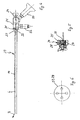
- the endoscope comprises a shaft 1 with a distal end 2 and a proximal end 3 and a main part 4.
- the shaft 1 has an outer tube 5 with a length of about 16 cm with a circular cross section with an outer diameter of about 7.5 mm, in which an inner tube 6 is inserted with an oval cross-section.
- the cross-section of the inner tube 6 is selected so that in the inserted state, as best seen in Fig. 3 it can be seen between the inner and outer tube 6, 5, a first channel 7, which is here in the suction channel is formed.
- a grip piece 9 which is connected to the outer tube 5 and which carries a shut-off valve 10 with a connecting piece 11 (eg Luer lock).
- a fluid connection between the connecting piece 11 and the first channel 7 can be made or interrupted.
- the check valve 10 (together with the connecting piece 11) is connected to the handle 9 so that it is rotatable about the longitudinal axis L of the shaft 1.
- a sleeve 12 is fixed, in which the proximal end of the inner tube 6 is inserted.
- the attachment of the inner tube 6 in the sleeve 12 may be made by means of soldering or welding. Alternatively, it is possible to form the main part 4 and the sleeve 12 in one piece.
- the handle 9 is slidably and rotatably supported in the longitudinal direction L, so that the outer tube 5 relative to the inner tube 6 is displaceable and rotatable.
- the sleeve 12 has an annular seal 13, which at the same time serves, in addition to the desired sealing of the proximal end of the first channel 7, to prescribe the necessary force required to move the outer tube 5 relative to the inner tube 6 in the longitudinal direction of the shaft 1 to move and / or rotate.
- Fig. 1 the endoscope is shown in a first end position, in which the distal ends of the inner and outer tubes 6, 5 are at the same height.
- Fig. 2 a second end position is shown, in which the distal end of the inner tube 6 protrudes from the outer tube 5.
- the sleeve 12 By using the sleeve 12, it is possible to provide a thin-walled inner tube 6 of small cross-sectional area for the shaft 1, which is particularly advantageous in medical applications (for example spinal operations). For the necessary stability to guide the handle 9 in the longitudinal displacement and / or rotation of the outer tube 5 relative to the inner tube 6 then provides the sleeve 12, which is formed thick-walled.
- an endoscope tube 14 is inserted with an oval cross-section.
- the cross section of the endoscope tube 14 is chosen so that between the inner tube 6 and the endoscope tube 14, a second channel 15 is formed.
- a shut-off valve 16 is arranged with a connection piece 17 for the second channel 15.
- the second channel 15 serves as a flushing channel.
- the check valve 16 and the connecting piece 17 are arranged on the main part 4, that they are rotatable about the longitudinal axis L of the shaft 1.
- an instrument tube 18 is arranged with a circular cross-section and an optical tube 19 with a circular cross-section, wherein the diameter of the optical tube 19 is smaller than that of the instrument tube (here 2.3 mm compared to 3.7 mm).
- the oval shape of the endoscope tube 14 is chosen so that the maximum clear width W1 in the region of the instrument tube 18 substantially corresponds to the outer diameter of the instrument tube 18 and the maximum clear width W2 in the region of the optical tube 19 substantially corresponds to the outer diameter of the optical tube 19.
- the endoscope tube 14 as can be seen in Fig. 3, a substantially egg-shaped cross-section.
- optical fibers within the endoscope tube 14 and between the instrument tube 18 and the optical tube 19 are still optical fibers (not shown), which serve to illuminate the object to be recorded.
- a lens optic known from optical endoscopes, which transmits the recorded image to an eyepiece 20 arranged at the proximal end of the endoscope.
- an electronic image sensor with, if necessary, upstream optics, be provided, which then the image signals via a electronic line to eye piece 20, which may then have a corresponding image display unit transmits.
- the optical tube 19, the instrument tube 18 and the endoscope tube 14 are fixedly connected to the proximal end of the endoscope tube 14 with an end piece 21 (for example, soldered or welded).
- an end piece 21 for example, soldered or welded.
- a connecting piece 22 is attached, via which the Lichtleitfasem be acted upon with light.
- the eye piece 20, via which either the recorded image can be viewed directly or to which a camera (not shown) can be connected, is releasably connected to the end piece 21.
- the instrument tube 18 extends through the end piece 21 and is sealed with a sealing system 24 so that the proximal end of the instrument tube 18 is sealed, regardless of whether an instrument inserted or not.
- a sealing system 24 for this purpose, the sealing system 24, as best seen in Fig. 5, a rubber sealing cap 25, with a central hole 26, whose size is chosen so that in an imported instrument, the seal by means of the sealing cap 25 takes place, and for example two Silicone Phillips gaskets 27 and 28 ( Figure 6) which, when installed, are twisted against each other so as to be sealing in the case where no instrument is inserted.
- the endoscope tube 14, the instrument tube 18, the optical tube 19, the Lichtleitfasem and the end piece 21 with the connection piece 22, the eye piece 20 and the sealing system 24 form an endoscope unit 29.
- the described endoscope unit 29 is a so-called 30 ° unit, since the recording direction B, as shown schematically in Fig. 4, is inclined with respect to the longitudinal direction by 30 °.
- the shaft 1 of the endoscope has the outer tube 5, the inner tube 6, the sleeve 12 and the corresponding parts of the endoscope unit 29 inserted therein.
- the endoscope unit 29 is connected by means disposed on the main part 4 quick locking unit 30 with the inner tube 6 so that the endoscope tube 14 is rotatably connected to the inner tube 6 and a shift in the longitudinal direction between the two tubes 14 and 6 is not possible.
- the end piece 21 has two locking pins 31 (only one of which is visible in Fig. 4) and a guide pin 32, as best seen in Fig. 4 can be seen.
- the quick lock unit 30 has, as best seen in Fig. 7, a handle 33 which is secured with a nut 34 on the sleeve 12 so that it is fixed in the axial direction. In the radial direction, which is shown in Fig. 7, the handle 33 is slidable, wherein it is moved by means of a disposed between the sleeve 12 and the handle 33 spring 35 in the locking position shown. The handle 33 can, as seen in Fig. 7, pressed down against the spring force and thereby moved to the unlocked position.
- At the proximal end of the handle 33 is one or two cutouts 36 (of which in Fig. 7 only one is visible) for the locking pins 31 and a longitudinal groove (not shown) for the guide pin 32 is provided.
- the endoscope tube 14 For connecting the endoscope tube 14 with the inner tube 6, the endoscope tube 14 is inserted from the proximal side into the inner tube 6, whereby the guide pin 31 engages in the longitudinal groove of the quick-locking unit 30.
- the shape of the cutout 36 is selected so that upon insertion of the endoscope tube 14 of the locking pin 31, the handle 33, seen in Fig. 7, presses down against the spring force of the spring 35.
- the locking pin 31 comes into a locking portion of the cutout 36, so that due to the restoring force of the spring 35, the handle 33 is pushed up again and thus locking the endoscope tube 14 relative to the inner tube 6 in the longitudinal direction Shank 1 causes.
- connection is rotationally fixed, so that the endoscope tube 14 rotatably and not longitudinally displaceable with the inner tube 6 is connected.
- the distance between the shut-off valve 16 and the connecting piece 22 and the eye piece 20 does not change.
- a conical portion 37 of the endoscope unit 29 seals against the conical sealing surface 38 of the sleeve so that the proximal end of the second channel 15 is sealed.
- the handle is pressed down and the endoscope unit 29 pulled out. If there is still an instrument in the instrument tube 18, this is preferably removed before pulling out the endoscope unit 29. If a camera is attached to the eyepiece 20, this can also before pulling out the Endoscope unit 29 from the eyepiece or together with the eyepiece (as needed) are separated from the endoscope unit. Thereafter, the 0 ° endoscope unit is inserted in the manner described and fixed by means of the quick-locking unit 30. Then the instrument can be inserted into the instrument channel and the camera (if desired) attached to the tail. Of course, endoscope units with other inclinations of the recording direction can be used, for. B. 45 ° and 70 °. A particular advantage of this exchange is that with the connecting pieces 11, 17 connected hoses must not be removed and replaced, so that the exchange is carried out quickly.
- the endoscope with the endoscope unit 29 and the further 0 ° endoscope unit forms an endoscope system, in which an exchange of the endoscope unit is easily carried out during the use of the endoscope. This is possible due to the modular design of the endoscope.
- the distal end 2 of the outer tube 5 is seen in the side view of Fig. 1 and 2, formed chamfered. This allows the distal end to be used as an instrument during surgery. In the same way, the distal end of the inner tube 6 is also formed chamfered.
- the endoscope is designed so that it can be completely disassembled.
- the outer tube 5 together with the handle 9 can be completely removed from the inner tube 6.
- the endoscope tube 14 can, as described, be separated from the inner tube 6. This allows the pipes to be cleaned and sterilized separately. In particular, this is advantageous when autoclaving.
- the handle has four flat sides, as indicated in the illustrations of Figs. 1 and 2.
Landscapes
- Health & Medical Sciences (AREA)
- Life Sciences & Earth Sciences (AREA)
- Surgery (AREA)
- Biomedical Technology (AREA)
- Medical Informatics (AREA)
- Optics & Photonics (AREA)
- Pathology (AREA)
- Radiology & Medical Imaging (AREA)
- Biophysics (AREA)
- Engineering & Computer Science (AREA)
- Physics & Mathematics (AREA)
- Heart & Thoracic Surgery (AREA)
- Nuclear Medicine, Radiotherapy & Molecular Imaging (AREA)
- Molecular Biology (AREA)
- Animal Behavior & Ethology (AREA)
- General Health & Medical Sciences (AREA)
- Public Health (AREA)
- Veterinary Medicine (AREA)
- Endoscopes (AREA)
- Instruments For Viewing The Inside Of Hollow Bodies (AREA)
- Eye Examination Apparatus (AREA)
Description
- Die Erfindung betrifft ein Endoskop, das insbesondere im medizinischen Bereich eingesetzt wird. Ein solches Endoskop gemäß dem Oberbegriff des Anspruchs 1 wird beispielsweise in US-A-6358200 beschrieben.
- Solche Endoskope müssen, wenn beispielsweise an der Wirbelsäule operiert wird, möglichst klein und gut sterilisierbar sein.
- Es ist daher Aufgabe der Erfindung, ein Endoskop bereitzustellen, das einen Schaft mit möglichst geringem Durchmesser und gleichzeitig mehrere Funktionalitäten aufweist.
- Erfindungsgemäß wird die Aufgabe gelöst durch ein Endoskop mit einem ein distales und ein proximales Ende aufweisenden Schaft, der ein äußeres Rohr aufweist, in dem ein inneres Rohr derart eingesetzt ist, daß es gegenüber dem äußeren Rohr verdrehbar sowie in Längsrichtung der Rohre verschiebbar ist und daß zwischen den beiden Rohren ein erster Kanal ausgebildet ist, und ferner mit einem mit dem proximalen Ende des Schafts verbundenen Hauptteil, wobei in dem inneren Rohr ein Instrumentenrohr sowie eine Bildaufnahmeoptik angeordnet sind und ein zweiter Kanal ausgebildet ist und wobei sowohl das Instrumentenrohr als auch die Bildaufnahmeoptik drehfest mit dem inneren Rohr verbunden sind.
- Da das Instrumentenrohr und die Bildaufnahmeoptik drehfest mit dem inneren Rohr verbunden sind, können das Instrumentenrohr und die Bildaufnahmeoptik gegenüber dem äußeren Rohr verdreht werden, was insbesondere bei der Verwendung des Endoskops im medizinischen Bereich von Vorteil ist. Für die Verdrehbarkeit des Instrumentenrohrs und der Bildaufnahmeoptik ist es bei dem erfindungsgemäßen Endoskop jedoch nicht notwendig, daß die Bildaufnahmeoptik und das Instrumentenrohr gegenüber dem inneren Rohr verdrehbar angeordnet sind. Damit wird es vorteilhaft möglich, die Querschnittsformen und Größen des Instrumentenrohrs und der Bildaufnahmeoptik relativ frei zu wählen.
- So kann mit dem erfindungsgemäßen Endoskop der Bereich am distalen Ende mittels der Bildaufnahmeoptik betrachtet werden und gleichzeitig kann mittels einem im Instrumentenrohr angeordneten Instrument in diesem Bereich manipuliert werden. Ferner können die zwei Kanäle noch als Spül- und Absaugkanal eingesetzt werden. Somit sind verschiedene Funktionalitäten beim erfindungsgemäßen Endoskop verwirklicht.
- Bevorzugt sind bei dem erfindungsgemäßen Endoskop sowohl das Instrumentenrohr als auch die Bildaufnahmeoptik so mit dem inneren Rohr verbunden, daß sie in Längsrichtung nicht gegenüber dem inneren Rohr verschiebbar sind.
- Das Instrumentenrohr, die Bildaufnahmeoptik und das innere Rohr bilden somit eine Einheit, die gegenüber dem äußeren Rohr drehbar und in der Längsrichtung verschiebbar ist.
- Durch das Vorsehen von zwei voneinander getrennten Kanälen im Schaft des Endoskops kann einer der beiden Kanäle als Spülkanal, über den eine Spülflüssigkeit dem am distalen Ende des Schafts liegenden Bereich zugeführt werden kann, und der andere Kanal als Absaugkanal eingesetzt werden, über den die Spülflüssigkeit wiederum am distalen Ende des Schafts abgesaugt wird.
- Insbesondere kann das äußere Rohr am distalen offen ausgebildet sein, und in einer Seitenansicht gesehen, relativ zur Längsrichtung des Schafts abgeschrägt ausgebildet sein. Dadurch wird das distale Ende selbst auch gleich als Instrument einsetzbar, was insbesondere bei Operationen an der Wirbelsäule als Werkzeug zum zur Seiteschieben von Nerven oder auch als Schutz der Nerven gegenüber einem Instrument, das durch das Instrumentenrohr am distalen Ende im zu operierenden Bereich eingesetzt wird, nützlich ist.
- Insbesondere ist sowohl das Instrumentenrohr als auch die Bildaufnahmeoptik lösbar mit dem inneren Rohr verbunden. Dies erleichtert die Sterilisation und insbesondere das Autoklavieren des Endoskops. In dieser Hinsicht kann das Endoskop ferner derart weitergebildet werden, daß auch das äußere Rohr vollständig von dem inneren Rohr abgezogen werden kann, so daß auch das äußere Rohr und das innere Rohr separat sterilisiert werden können.
- Ferner kann beim erfindungsgemäßen Endoskop am proximalen Ende des Schafts bzw. des äußeren Rohrs ein erstes Absperrventil angeordnet sein, das mit dem ersten Kanal in Verbindung steht. Dieses Absperrventil ist bevorzugt um die Längsrichtung bzw. um eine Achse parallel zur Längsrichtung drehbar angeordnet. Damit läßt sich das Absperrventil in eine gewünschte Stellung relativ zum Schaft bringen.
- Ferner kann am proximalen Ende des Schafts bzw. des inneren Rohrs ein zweites Absperrventil angeordnet sein, das mit dem zweiten Kanal in Verbindung steht. Bevorzugt ist auch das zweite Abspenventil so angeordnet, daß es um die Längsrichtung bzw. um eine Achse parallel zur Längsrichtung drehbar ist. Damit ist auch das zweite Absperrventil relativ zum Schaft relativ frei positionierbar.
- Die Kombination der Absperrventile mit dem Merkmal, daß das Instrumentenrohr und die Bildaufnahmeoptik lösbar mit dem inneren Rohr verbunden sind, bringt den Vorteil mit sich, daß das Instrumentenrohr und die Bildaufnahmeoptik ausgewechselt werden können, ohne daß mit den Absperrventilen verbundene Schläuche entfernt und wieder angebracht werden müssen. Dies führt insbesondere bei medizinischer Anwendung zu einer verbesserten Ergonomie.
- Besonders bevorzugt ist es, wenn das innere Rohr einen ovalen Querschnitt aufweist. Dadurch läßt sich einerseits die Verdrehbarkeit des inneres Rohrs gegenüber dem äußeren Rohr sicherstellen und andererseits ist der erste Kanal zwischen dem äußeren Rohr und inneren Rohr vorgesehen.
- Ferner kann bei dem erfindungsgemäßen Endoskop das innere Rohr am distalen Ende offen und, in einer Seitenansicht, relativ zur Längsrichtung abgeschrägt ausgebildet sein.
- Besonders bevorzugt ist es bei dem erfindungsgemäßen Endoskop, wenn das Instrumentenrohr und die Bildaufnahmeoptik innerhalb eines Endoskoprohrs angeordnet sind, das seinerseits in das innere Rohr derart eingesetzt ist, daß zwischen dem inneren Rohr und dem Endoskoprohr der zweite Kanal ausgebildet ist. Durch diese Ausbildung wird die gesamte Anordnung der Rohre sehr platzsparend realisiert.
- Besonders vorteilhaft ist es dann, wenn das Endoskoprohr einen ovalen Querschnitt aufweist, der so gewählt ist, daß im Querschnitt gesehen, die maximale lichte Weite im Bereich des Instrumentenrohrs größer ist als die maximale lichte Weite im Bereich der Bildaufnahmeoptik. Dadurch kann ein Instrumentenrohr mit einer größeren Querschnittsfläche als die Bildaufnahmeoptik vorgesehen werden, wodurch vorteilhaft der Platz für die Instrumente größer wird.
- Bei einer bevorzugten Ausgestaltung des erfindungsgemäßen Endoskops ist am proximalen Ende des Instrumentenrohrs ein Dichtsystem ausgebildet, das das proximale Ende des Instrumentenrohrs unabhängig davon abdichtet, ob ein Instrumentenrohr eingeführt ist oder nicht.
- Dazu kann das Dichtsystem zwei Dichteinheiten aufweisen, wobei die erste Dichteinheit für die Abdichtung sorgt, wenn ein Instrument eingesetzt ist, und die zweite Dichteinheit für die Abdichtung sorgt, wenn kein Instrument eingesetzt ist. Die zwei Dichteinheiten sind bevorzugt, in Längsrichtung des Instrumentenrohrs gesehen, hintereinander angeordnet.
- Insbesondere kann das erfindungsgemäße Endoskop so weitergebildet werden, daß das Instrumentenrohr und die Bildaufnahmeoptik miteinander verbunden sind und eine erste Endoskopeinheit bilden, und daß eine zweite Endoskopeinheit mit einem weiteren Instrumentenrohr und einer weiteren Bildaufnahmeoptik vorgesehen ist, wobei die Endoskopeinheiten abwechselnd in das innere Rohr einsetzbar und im eingesetzten Zustand mit dem inneren Rohr verbindbar sind. Damit wird ein Endoskop bzw. Endoskopsystem bereitgestellt, bei dem die Endoskopeinheiten leicht austauschbar sind. Da die eingesetzten Endoskopeinheiten austauschbar ausgebildet sind, kann der Austausch während des bestimmungsgemäßen Gebrauchs des Endoskops durchgeführt werden (beispielsweise während einer Operation).
- Die zweite Endoskopeinheit kann in gleicher Weise wie die oben beschriebene erste Endoskopeinheit weitergebildet werden. Die beiden Endoskopeinheiten können sich insbesondere in einem Merkmal unterscheiden. Dies kann beispielsweise die Blickrichtung der Bildaufnahmeoptik bezogen auf die Längsrichtung sein.
- Natürlich kann das Endoskopsystem mehr als zwei Endoskopeinheiten aufweisen, die sich bevorzugt zumindest in einem Merkmal (z. B. die Blickrichtung der Bildaufnahmeoptik) unterscheiden.
- Für die Verbindung zwischen der entsprechenden Endoskopeinheit und dem inneren Rohr kann eine Verriegelungseinheit am Hauptteil (bevorzugt am proximalen Ende des Hauptteils) ausgebildet sein, mit der die gewünschte Verbindung realisierbar und auch wieder lösbar ist.
- Die Erfindung wird nachfolgend unter Bezugnahme auf die Zeichnungen beispielshalber noch näher erläutert. Von den Zeichnungen zeigen:
- Fig. 1
- eine erste Ausführungsform des erfindungsgemäßen Endoskops in einer ersten Betriebsstellung,
- Fig. 2
- das Endoskop von Fig. 1 in einer zweiten Betriebsstellung,
- Fig. 3
- den Schnitt A-A des Schafts von Fig. 1,
- Fig. 4.
- eine Ansicht der Endoskopeinheit des Endoskops von Fig. 1 und 2, und
- Fig. 5
- eine vergrößerte Schnittdarstellung des Dichtsystems am proximalen Ende des Endoskops von Fig. 1 und 2,
- Fig. 6
- eine Darstellung einer Kreuzschlitzdichtung des Dichtsystems von Fig. 5 und
- Fig. 7
- eine vergrößerte Schnittdarstellung der Schnellverriegelungseinheit des in Fig. 1 und 2 gezeigten Endoskops
- Das Endoskop umfaßt einen Schaft 1 mit einem distalen Ende 2 und einem proximalen Ende 3 sowie ein Hauptteil 4.
- Der Schaft 1 weist ein äußeres Rohr 5 mit einer Länge von ca. 16 cm mit kreisrundem Querschnitt mit einem Außendurchmesser von ca. 7,5 mm auf, in das ein inneres Rohr 6 mit ovalem Querschnitt eingesetzt ist. Der Querschnitt des inneres Rohrs 6 ist so gewählt, daß im eingesetzten Zustand, wie am besten aus Fig. 3 ersichtlich ist, zwischen dem inneren und äußeren Rohr 6, 5 ein erster Kanal 7, der hier in Absaugkanal ist, ausgebildet ist. Am proximalen Ende 8 des äußeres Rohrs 5 ist ein mit dem äußeren Rohr 5 verbundenes Griffstück 9 angeordnet, das ein Absperrventil 10 mit einem Anschlußstutzen 11 (z. B. Luer Lock) trägt. Mittels dem Absperrventil 10 kann eine Fluidverbindung zwischen dem Anschlußstutzen 11 und dem ersten Kanal 7 hergestellt oder unterbrochen werden. Das Absperrventil 10 (zusammen mit dem Anschlußstutzen 11) ist so mit dem Griffstück 9 verbunden, daß es um die Längsachse L des Schafts 1 drehbar ist.
- An dem Hauptteil 4 ist eine Hülse 12 befestigt, in die das proximale Ende des inneres Rohrs 6 eingesetzt ist. Die Befestigung des inneren Rohrs 6 in der Hülse 12 kann mittels Löten oder Schweißen hergestellt sein. Alternativ ist es möglich, das Hauptteil 4 und die Hülse 12 einstückig auszubilden. Auf der Außenseite der Hülse 12 ist das Griffstück 9 in Längsrichtung L verschiebbar und drehbar gelagert, so daß das äußere Rohr 5 gegenüber dem inneren Rohr 6 verschiebbar und drehbar ist. Die Hülse 12 weist eine Ringdichtung 13 auf, die neben der gewünschten Abdichtung des proximalen Endes des ersten Kanals 7 auch gleichzeitig noch dazu dient, die notwendige Kraft vorzugeben, die benötigt wird, um das äußere Rohr 5 gegenüber dem inneren Rohr 6 in Längsrichtung des Schafts 1 zu verschieben und/oder zu drehen.
- In Fig. 1 ist das Endoskop in einer ersten Endstellung gezeigt, in der die distalen Enden des inneren und äußeren Rohrs 6, 5 auf gleicher Höhe sind. In Fig. 2 ist eine zweite Endstellung gezeigt, in der das distale Ende des inneren Rohrs 6 aus dem äußeren Rohr 5 vorsteht.
- Durch die Verwendung der Hülse 12, ist es möglich, ein dünnwandiges inneres Rohr 6 mit kleiner Querschnittsfläche für den Schaft 1 bereitzustellen, was insbesondere bei medizinischen Anwendungen (beispielsweise Operationen der Wirbelsäule) von Vorteil ist. Für die notwendige Stabilität zur Führung des Griffstücks 9 bei der Längsverschiebung und/oder der Drehung des äußeren Rohrs 5 gegenüber dem inneren Rohr 6 sorgt dann die Hülse 12, die dickwandiger ausgebildet ist.
- Wie am bestens aus Fig. 3 ersichtlich ist, ist in dem inneren Rohr 6 ein Endoskoprohr 14 mit ovalem Querschnitt eingesetzt. Der Querschnitt des Endoskoprohrs 14 ist dabei so gewählt, daß zwischen dem inneren Rohr 6 und dem Endoskoprohr 14 ein zweiter Kanal 15 ausgebildet ist. Am Hauptteil 4 ist für den zweiten Kanal 15 ein Absperrventil 16 mit einem Anschlußstutzen 17 angeordnet. Mittels dem Absperrventil 16 kann eine Fluidverbindung zwischen dem zweiten Kanal 15 und dem Anschlußstutzen 17 hergestellt und unterbrochen werden. In dem hier beschriebenen Ausführungsbeispiel dient der zweite Kanal 15 als Spülkanal. Das Absperrventil 16 und der Anschlußstutzen 17 sind so am Hauptteil 4 angeordnet, daß sie um die Längsachse L des Schafts 1 drehbar sind.
- Innerhalb des Endoskoprohrs 14 ist ein Instrumentenrohr 18 mit kreisrundem Querschnitt und ein Optikrohr 19 mit kreisrundem Querschnitt angeordnet, wobei der Durchmesser des Optikrohrs 19 kleiner ist als der des Instrumentenrohrs (hier 2,3 mm gegenüber 3,7 mm). Die ovale Form des Endoskoprohrs 14 ist so gewählt, daß die maximale lichte Weite W1 im Bereich des Instrumentenrohrs 18 im wesentlichen dem Außendurchmesser des Instrumentenrohrs 18 entspricht und die maximale lichte Weite W2 im Bereich des Optikrohrs 19 im wesentlichen dem Außendurchmesser des Optikrohrs 19 entspricht. Damit weist das Endoskoprohr 14, wie in Fig. 3 ersichtlich ist, einen im wesentlichen eiförmigen Querschnitt auf.
- Innerhalb des Endoskoprohrs 14 und zwischen dem Instrumentenrohr 18 und dem Optikrohr 19 sind noch Lichtleitfasern (nicht eingezeichnet) angeordnet, die zur Beleuchtung des aufzunehmenden Objektes dienen. In dem Optikrohr 19 ist eine aus optischen Endoskopen bekannte Linsenoptik angeordnet, die das aufgenommene Bild bis zu einem am proximalen Ende des Endoskops angeordneten Augenstücks 20 überträgt. Natürlich kann anstatt der Linsenoptik beispielsweise am distalen Ende des Optikrohrs 19 ein elektronischer Bildsensor mit, falls notwendig, vorgeschalteter Optik, vorgesehen sein, der dann die Bildsignale über eine elektronische Leitung zum Augenstück 20, das dann eine entsprechende Bildanzeigeeinheit aufweisen kann, überträgt.
- Das Optikrohr 19, das Instrumentenrohr 18 und das Endoskoprohr 14 sind am proximalen Ende des Endoskoprohrs 14 mit einem Endstück 21 fest verbunden (beispielsweise verlötet oder verschweißt). An dem Endstück 21 ist ein Anschlußstutzen 22 befestigt, über den die Lichtleitfasem mit Licht beaufschlagbar sind. Ferner ist das Augenstück 20, über das entweder direkt das aufgenommene Bild betrachtet werden kann oder an das eine Kamera (nicht gezeigt) anschließbar ist, mit dem Endstück 21 lösbar verbunden. Dies bringt den Vorteil mit sich, daß, wenn am Augenstück 20 eine Kamera mit einer sterilen Abdeckung befestigt ist, wie dies bei Operationen vorkommen kann, bei Wechsel des Endoskoprohrs 14 das Augenstück 20 von dem Endoskoprohr gelöst werden (zusammen mit der Kamera) und dann an dem neuen Endoskoprohr gleich wieder befestigt werden kann.
- Das Instrumentenrohr 18 verläuft durch das Endstück 21 hindurch und ist mit einem Dichtsystem 24 so abgedichtet, daß das proximale Ende des Instrumentenrohrs 18 abgedichtet ist, unabhängig davon ob ein Instrument eingeführt oder nicht. Dazu weist das Dichtsystem 24, wie am besten aus Fig. 5 ersichtlich ist, eine Gummi-Dichtkappe 25, mit einem zentralen Loch 26, dessen Größe so gewählt ist, daß bei einem eingeführten Instrument die Abdichtung mittels der Dichtkappe 25 erfolgt, sowie beispielsweise zwei Silikon-Kreuzschlitzdichtungen 27 und 28 (Fig. 6) auf, die im eingebauten Zustand so gegeneinander verdreht sind, daß sie dichtend in dem Fall wirken, in dem kein Instrument eingesetzt ist.
- Das Endoskoprohr 14, das Instrumentenrohr 18, das Optikrohr 19, die Lichtleitfasem und das Endstück 21 mit dem Anschlußstutzen 22, dem Augenstück 20 und dem Dichtsystem 24 bilden eine Endoskopeinheit 29. Die beschriebene Endoskopeinheit 29 ist eine sogenannte 30°-Einheit, da die Aufnahmerichtung B, wie in Fig. 4 schematisch eingezeichnet ist, gegenüber der Längsrichtung um 30° geneigt ist. Der Schaft 1 des Endoskops weist das äußere Rohr 5, das innere Rohr 6, die Hülse 12 und die entsprechenden Teile der darin eingesetzten Endoskopeinheit 29 auf.
- Um nun beispielsweise während einer Operation einen schnellen Austausch der Endoskopeinheit 29 durchführen zu können (ohne das gesamte Endoskop aus dem zu operierenden Bereich entfernen zu müssen), da der Operateur z. B. eine 0°-Endoskopeinheit benötigt (Aufnahmerichtung entlang der Längsrichtung), ist die Endoskopeinheit 29 mittels einer am Hauptteil 4 angeordneten Schnellverriegelungseinheit 30 mit dem inneren Rohr 6 so verbindbar, daß das Endoskoprohr 14 mit dem inneren Rohr 6 drehfest verbunden ist und eine Verschiebung in Längsrichtung zwischen den beiden Rohren 14 und 6 nicht möglich ist.
- Es wird zuerst das Einsetzen der Endoskopeinheit 29 beschrieben. Das Endstück 21 weist zwei Verriegelungsstifte 31 (von denen in Fig. 4 nur einer sichtbar ist) sowie ein Führungsstift 32 auf, wie am besten aus Fig. 4 ersichtlich ist. Die Schnellverriegelungseinheit 30 weist, wie am besten aus Fig. 7 ersichtlich ist, ein Griffstück 33 auf, das mit einer Mutter 34 an der Hülse 12 so befestigt ist, daß es in axialer Richtung fixiert ist. In der radialen Richtung, die in Fig. 7 gezeigt ist, ist das Griffstück 33 verschiebbar, wobei es mittels einer zwischen der Hülse 12 und dem Griffstück 33 angeordneten Feder 35 in die gezeigte Verriegelungsposition bewegt ist. Das Griffstück 33 kann, in Fig. 7 gesehen, nach unten gegen die Federkraft gedrückt und dadurch in die Entriegelungsposition bewegt werden. Am proximalen Ende des Griffstücks 33 ist eine bzw. zwei Ausfräsungen 36 (von denen in Fig. 7 nur einer sichtbar ist) für die Verriegelungsstifte 31 sowie eine Längsnut (nicht gezeigt) für den Führungsstift 32 vorgesehen.
- Zum Verbinden des Endoskoprohrs 14 mit dem inneren Rohr 6 wird das Endoskoprohr 14 von der proximalen Seite in das innere Rohr 6 eingeschoben, wobei dabei der Führungsstift 31 in die Längsnut der Schnellverriegelungseinheit 30 eingreift. Die Form der Ausfräsung 36 ist so gewählt, daß beim Einschieben des Endoskoprohrs 14 der Verriegelungsstift 31 das Griffstück 33, in Fig. 7 gesehen, nach unten gegen die Federkraft der Feder 35 drückt. Wenn das Endoskoprohr 14 weiter eingeschoben wird, kommt der Verriegelungsstift 31 in einen Verriegelungsabschnitt der Ausfräsung 36, so daß aufgrund der Rückstellkraft der Feder 35 das Griffstück 33 wieder nach oben gedrückt wird und damit eine Verriegelung des Endoskoprohrs 14 gegenüber dem inneren Rohr 6 in Längsrichtung des Schaftes 1 bewirkt. Der in der Nut eingreifende Führungsstift 31 führt dazu, daß die Verbindung drehfest ist, so daß das Endoskoprohr 14 drehfest und nicht längsverschieblich mit dem inneren Rohr 6 verbunden ist. Damit ändert sich bei Bewegung des inneren Rohrs 6 gegenüber dem äußeren Rohr 5 der Abstand zwischen dem Absperrventil 16 und dem Anschlußstutzen 22 und dem Augenstück 20 nicht. Bei der so erzeugten Verbindung liegt ein konischer Abschnitt 37 der Endoskopeinheit 29 dichtend an der konischen Dichtfläche 38 der Hülse so an, daß das proximale Ende des zweiten Kanals 15 abgedichtet ist.
- Zum Lösen der Endoskopeinheit 29 muß lediglich das Griffstück 33 nach unten gegen die Feder 35 gedrückt werden und danach das Endoskoprohr 14 an seinem Endstück 21 nach rechts (in Fig. 1 und 2) aus dem inneren Rohr 6 herausgezogen werden.
- Um nun den beschriebenen Austausch durchzuführen, wird das Griffstück nach unten gedrückt und die Endoskopeinheit 29 herausgezogen. Sofern noch ein Instrument im Instrumentenrohr 18 ist, wird dies bevorzugt vor dem Herausziehen der Endoskopeinheit 29 entfernt. Falls an dem Augenstück 20 eine Kamera befestigt ist, kann diese ebenfalls vor dem Herausziehen der Endoskopeinheit 29 von dem Augenstück oder zusammen mit dem Augenstück (je nach Bedarf) von der Endoskopeinheit getrennt werden. Danach wird die 0°-Endoskopeinheit in der beschriebenen Weise eingesetzt und mittels der Schnellverriegelungseinheit 30 fixiert. Darauf kann dann das Instrument in den Instrumentenkanal eingeführt und die Kamera (falls gewünscht) am Endstück befestigt werden. Natürlich können auch Endoskopeinheiten mit anderen Neigungen der Aufnahmerichtung verwendet werden, z. B. 45° und 70°. Ein besonderer Vorteil bei diesem Austausch besteht darin, daß mit den Anschlußstutzen 11, 17 verbundene Schläuche nicht entfernt und wieder angebracht werden müssen, so daß der Austausch schnell durchführbar ist.
- Das Endoskop mit der Endoskopeinheit 29 und der weiteren 0°-Endoskopeinheit bildet ein Endoskopsystem, bei dem während der Verwendung des Endoskops ein Austausch der Endoskopeinheit leicht durchführbar ist. Dies ist aufgrund des modularen Aufbaus des Endoskops möglich.
- Das distale Ende 2 des äußeren Rohrs 5 ist in der Seitenansicht von Fig. 1 und 2 gesehen, abgeschrägt ausgebildet. Damit kann das distale Ende bei Operationen auch gleich als Instrument verwendet werden. In gleicher Weise ist das distale Ende des inneren Rohrs 6 auch abgeschrägt ausgebildet.
- Das Endoskop ist so ausgebildet, daß es vollständig zerlegt werden kann. So kann das äußere Rohr 5 zusammen mit Griffstück 9 vollkommen von dem inneren Rohr 6 abgezogen werden. Auch das Endoskoprohr 14 kann, wie beschrieben, von dem inneren Rohr 6 getrennt werden. Damit können die Rohre voneinander getrennt gereinigt und sterilisiert werden. Insbesondere ist dies beim Autoklavieren von Vorteil.
- Um einen sichereren Griff am Griffstück zu ermöglichen, weist das Griffstück vier flache Seiten auf, wie in den Darstellungen von Fig. 1 und 2 angedeutet ist.
Claims (12)
- Endoskop mit einem ein distales und ein proximales Ende (2, 3) aufweisenden Schaft (1), der ein äußeres Rohr (5) aufweist, in dem ein inneres Rohr (6) derart eingesetzt ist, daß es gegenüber dem äußeren Rohr (5) verdrehbar ist und daß zwischen den beiden Rohren (5, 6) ein erster Kanal (7) ausgebildet ist, wobei in dem inneren Rohr (6) eine Bildaufnahmeoptik (19) angeordnet ist und ein zweiter Kanal (15) ausgebildet ist und wobei die Bildaufnahmeoptik (19) drehfest mit dem inneren Rohr (6) verbunden ist, dadurch charakterisiert, dass das innere Rohr (6) gegenüber dem äußeren Rohr in Längsrichtung der Rohre (5, 6) verschiebbar ist und dass in dem inneren Rohr drehfest ein Instrumentenrohr (18) angeordnet ist.
- Endoskop nach Anspruch 1, bei dem sowohl das Instrumentenrohr (18) als auch die Bildaufnahmeoptik (19) so mit dem inneren Rohr (6) verbunden sind, daß sie in Längsrichtung nicht gegenüber dem inneren Rohr (6) verschiebbar sind.
- Endoskop nach einem der obigen Ansprüche, bei dem das äußere Rohr (5) am distalen Ende (2) offen ist und, in einer Seitenansicht gesehen, relativ zur Längsrichtung (L) des Schafts (1) abgeschrägt ausgebildet ist.
- Endoskop nach einem der obigen Ansprüche, bei dem sowohl das Instrumentenrohr (18) als auch die Bildaufnahmeoptik (19) lösbar mit dem inneren Rohr (6) verbunden sind.
- Endoskop nach einem der obigen Ansprüche, bei dem am proximalen Ende (3) des Schafts (1) ein erstes Absperrventil (10) angeordnet ist, das mit dem ersten Kanal (7) in Verbindung steht und das bevorzugt drehbar um die Längsrichtung (L) oder um eine Achse parallel zur Längsrichtung (L) angeordnet und ferner bevorzugt so mit dem äußeren Rohr (5) verbunden ist, daß es in Längsrichtung nicht gegenüber dem äußeren Rohr (5) verschiebbar ist.
- Endoskop nach einem der obigen Ansprüche, bei dem am proximalen Ende des Schafts (1) ein zweites Absperrventil (16) angeordnet, das mit dem zweiten Kanal (15) in Verbindung steht und das bevorzugt drehbar um die Längsrichtung (L) oder um eine Achse parallel zur Längsrichtung (L) angeordnet und ferner bevorzugt so mit dem inneren Rohr (6) verbunden ist, daß es in Längsrichtung nicht gegenüber dem inneren Rohr (6) verschiebbar ist.
- Endoskop nach einem der obigen Ansprüche, bei dem das innere Rohr (6) einen ovalen Querschnitt aufweist.
- Endoskop nach einem der obigen Ansprüche, bei dem das innere Rohr (6) am distalen Ende offen ist und, in einer Seitenansicht gesehen, relativ zur Längsrichtung abgeschrägt ausgebildet ist.
- Endoskop nach einem der obigen Ansprüche, bei dem das Instrumentenrohr (18) und die Bildaufnahmeoptik (19) innerhalb eines Endoskoprohrs (14) angeordnet sind, das in das innere Rohr (6) derart eingesetzt ist, daß zwischen dem inneren Rohr (6) und dem Endoskoprohr (14) der zweite Kanal (15) ausgebildet ist.
- Endoskop nach Anspruch 9, bei dem das Endoskoprohr (14) einen ovalen Querschnitt aufweist, wobei, im Querschnitt gesehen, die maximale lichte Weite im Bereich des Instrumentenrohrs (18) größer ist als die maximale lichte Weite im Bereich der Bildaufnahmeoptik (19).
- Endoskop nach einem der obigen Ansprüche, bei dem am proximalen Ende des Instrumentenrohrs (18) ein Dichtsystem (24) angeordnet ist, das das proximale Ende des Instrumentenrohrs (18) unabhängig davon abdichtet, ob in das Instrumentenrohr ein Instrument eingeführt ist oder nicht.
- Endoskop nach einem der obigen Ansprüche, bei dem das Instrumentenrohr (18) und die Bildaufnahmeoptik (19) miteinander verbunden sind und eine erste Endoskopeinheit (29) bilden, und bei dem eine zweite Endoskopeinheit mit einem weiteren Instrumentenrohr und einer weiteren Bildaufnahmeoptik vorgesehen ist, wobei die Endoskopeinheiten (29) jeweils in das innere Rohr (6) einsetzbar und im eingesetzten Zustand mit dem inneren Rohr (6) verbindbar sind.
Priority Applications (6)
| Application Number | Priority Date | Filing Date | Title |
|---|---|---|---|
| DE50303217T DE50303217D1 (de) | 2003-10-17 | 2003-10-17 | Endoskop |
| ES03023645T ES2260557T3 (es) | 2003-10-17 | 2003-10-17 | Endoscopio. |
| EP03023645A EP1523932B1 (de) | 2003-10-17 | 2003-10-17 | Endoskop |
| AT03023645T ATE324826T1 (de) | 2003-10-17 | 2003-10-17 | Endoskop |
| JP2004285937A JP4109662B2 (ja) | 2003-10-17 | 2004-09-30 | 内視鏡 |
| US10/967,063 US20050085692A1 (en) | 2003-10-17 | 2004-10-15 | Endoscope |
Applications Claiming Priority (1)
| Application Number | Priority Date | Filing Date | Title |
|---|---|---|---|
| EP03023645A EP1523932B1 (de) | 2003-10-17 | 2003-10-17 | Endoskop |
Publications (2)
| Publication Number | Publication Date |
|---|---|
| EP1523932A1 EP1523932A1 (de) | 2005-04-20 |
| EP1523932B1 true EP1523932B1 (de) | 2006-05-03 |
Family
ID=34354508
Family Applications (1)
| Application Number | Title | Priority Date | Filing Date |
|---|---|---|---|
| EP03023645A Expired - Lifetime EP1523932B1 (de) | 2003-10-17 | 2003-10-17 | Endoskop |
Country Status (6)
| Country | Link |
|---|---|
| US (1) | US20050085692A1 (de) |
| EP (1) | EP1523932B1 (de) |
| JP (1) | JP4109662B2 (de) |
| AT (1) | ATE324826T1 (de) |
| DE (1) | DE50303217D1 (de) |
| ES (1) | ES2260557T3 (de) |
Families Citing this family (78)
| Publication number | Priority date | Publication date | Assignee | Title |
|---|---|---|---|---|
| NL1006944C2 (nl) | 1997-09-04 | 1999-03-11 | Mark Hans Emanuel | Chirurgische endoscopische snij-inrichting. |
| US7226459B2 (en) | 2001-10-26 | 2007-06-05 | Smith & Nephew, Inc. | Reciprocating rotary arthroscopic surgical instrument |
| DE10154163A1 (de) | 2001-11-03 | 2003-05-22 | Advanced Med Tech | Vorrichtung zum Aufrichten und Stabilisieren der Wirbelsäule |
| US8062214B2 (en) | 2004-08-27 | 2011-11-22 | Smith & Nephew, Inc. | Tissue resecting system |
| USD536790S1 (en) * | 2005-06-08 | 2007-02-13 | Karl Storz Gmbh & Co. Kg | Medical scope |
| DE102005051209A1 (de) † | 2005-10-18 | 2007-04-19 | Karl Storz Gmbh & Co. Kg | Endoskop |
| US8979931B2 (en) | 2006-12-08 | 2015-03-17 | DePuy Synthes Products, LLC | Nucleus replacement device and method |
| JP5075437B2 (ja) * | 2007-03-19 | 2012-11-21 | オリンパス株式会社 | 内視鏡用冷却装置及び内視鏡装置 |
| US20090088789A1 (en) | 2007-09-28 | 2009-04-02 | O'neil Michael J | Balloon With Shape Control For Spinal Procedures |
| US9387009B2 (en) | 2007-10-05 | 2016-07-12 | DePuy Synthes Products, Inc. | Dilation system and method of using the same |
| DE102007055582A1 (de) * | 2007-11-20 | 2009-05-28 | Olympus Winter & Ibe Gmbh | Urologisches Resektoskop mit Löchern |
| FR2942393B1 (fr) * | 2009-02-25 | 2011-03-04 | Charles Henri Pineau | Dispositif multifonctions d'exploration et/ou d'intervention notamment a usage medical |
| WO2011060192A1 (en) * | 2009-11-13 | 2011-05-19 | Interlace Medical, Inc. | Access system with removable outflow channel |
| US9155454B2 (en) * | 2010-09-28 | 2015-10-13 | Smith & Nephew, Inc. | Hysteroscopic system |
| DE102010056025A1 (de) | 2010-12-27 | 2012-06-28 | Olympus Winter & Ibe Gmbh | Endoskop mit einem Schaftrohr |
| JP2015501418A (ja) * | 2011-09-30 | 2015-01-15 | ジーイー・ヘルスケア・リミテッド | 放射性医薬品合成用カセット |
| US9622779B2 (en) | 2011-10-27 | 2017-04-18 | DePuy Synthes Products, Inc. | Method and devices for a sub-splenius / supra-levator scapulae surgical access technique |
| WO2013067179A2 (en) | 2011-11-01 | 2013-05-10 | Synthes Usa, Llc | Dilation system |
| US9265490B2 (en) | 2012-04-16 | 2016-02-23 | DePuy Synthes Products, Inc. | Detachable dilator blade |
| US9480855B2 (en) | 2012-09-26 | 2016-11-01 | DePuy Synthes Products, Inc. | NIR/red light for lateral neuroprotection |
| DE202013000025U1 (de) * | 2013-01-07 | 2013-01-29 | Schölly Fiberoptic GmbH | Endoskop |
| TWI563959B (zh) * | 2013-06-17 | 2017-01-01 | 國立臺灣大學 | 內視鏡及其構件的改質方法 |
| US9788856B2 (en) | 2014-03-11 | 2017-10-17 | Stryker European Holdings I, Llc | Endoscopic surgical systems and methods |
| US9980737B2 (en) | 2014-08-04 | 2018-05-29 | Medos International Sarl | Flexible transport auger |
| DE102014111354A1 (de) * | 2014-08-08 | 2016-02-25 | Karl Storz Gmbh & Co. Kg | Sterilhülle für ein medizinisches Beobachtungsinstrument sowie Verfahren zum Betreiben eines medizinischen Beobachtungsinstruments |
| US10264959B2 (en) | 2014-09-09 | 2019-04-23 | Medos International Sarl | Proximal-end securement of a minimally invasive working channel |
| US9924979B2 (en) | 2014-09-09 | 2018-03-27 | Medos International Sarl | Proximal-end securement of a minimally invasive working channel |
| US10111712B2 (en) | 2014-09-09 | 2018-10-30 | Medos International Sarl | Proximal-end securement of a minimally invasive working channel |
| WO2016100522A1 (en) | 2014-12-16 | 2016-06-23 | Smith & Nephew, Inc. | Surgical device with incorporated tissue extraction |
| WO2016122500A1 (en) | 2015-01-28 | 2016-08-04 | Smith & Nephew, Inc. | Tissue resection system |
| CN107257648B (zh) * | 2015-02-27 | 2020-04-03 | 柯惠有限合伙公司 | 具有零度视场角的倾斜尖端内窥镜 |
| US10786264B2 (en) | 2015-03-31 | 2020-09-29 | Medos International Sarl | Percutaneous disc clearing device |
| WO2016191422A1 (en) | 2015-05-26 | 2016-12-01 | Covidien Lp | Systems and methods for generating a fluid bearing for an operative procedure |
| US10804769B2 (en) | 2015-06-17 | 2020-10-13 | Covidien Lp | Surgical instrument with phase change cooling |
| DE102015211424A1 (de) * | 2015-06-22 | 2016-12-22 | Olympus Winter & Ibe Gmbh | Chirurgisches Instrument, insbesondere Ureteroskop |
| USD790697S1 (en) | 2015-07-31 | 2017-06-27 | Covidien Lp | Endoscope with oblique tip |
| USD791317S1 (en) | 2015-07-31 | 2017-07-04 | Covidien Lp | Sheath and endoscope with oblique tips |
| USD782026S1 (en) | 2015-08-04 | 2017-03-21 | Covidien Lp | Endoscope sheath with oblique tip |
| US11672562B2 (en) | 2015-09-04 | 2023-06-13 | Medos International Sarl | Multi-shield spinal access system |
| US11439380B2 (en) | 2015-09-04 | 2022-09-13 | Medos International Sarl | Surgical instrument connectors and related methods |
| CN113143355A (zh) | 2015-09-04 | 2021-07-23 | 美多斯国际有限公司 | 多护罩脊柱进入系统 |
| US12150636B2 (en) | 2015-09-04 | 2024-11-26 | Medos International Sárl | Surgical instrument connectors and related methods |
| US11744447B2 (en) | 2015-09-04 | 2023-09-05 | Medos International | Surgical visualization systems and related methods |
| US10987129B2 (en) | 2015-09-04 | 2021-04-27 | Medos International Sarl | Multi-shield spinal access system |
| US10299838B2 (en) | 2016-02-05 | 2019-05-28 | Medos International Sarl | Method and instruments for interbody fusion and posterior fixation through a single incision |
| US11864735B2 (en) * | 2016-05-26 | 2024-01-09 | Covidien Lp | Continuous flow endoscope |
| US10299819B2 (en) | 2016-07-28 | 2019-05-28 | Covidien Lp | Reciprocating rotary surgical cutting device and system for tissue resecting, and method for its use |
| US10299803B2 (en) | 2016-08-04 | 2019-05-28 | Covidien Lp | Self-aligning drive coupler |
| US10772654B2 (en) | 2017-03-02 | 2020-09-15 | Covidien Lp | Fluid-driven tissue resecting instruments, systems, and methods |
| CN107080513B (zh) * | 2017-05-17 | 2018-10-16 | 武汉佑康科技有限公司 | 一种模块化内窥镜 |
| JP2019042075A (ja) * | 2017-08-31 | 2019-03-22 | シャープ株式会社 | 体内撮像装置、および体内監視カメラシステム |
| WO2019152727A1 (en) | 2018-02-02 | 2019-08-08 | Kalera Medical, Inc. | Devices and methods for minimally invasive kidney stone removal by combined aspiration and irrigation |
| US11259858B1 (en) * | 2018-02-06 | 2022-03-01 | Jason RAHIMZADEH | Endoscopy tube and device for cryotherapy |
| US10869684B2 (en) | 2018-02-13 | 2020-12-22 | Covidien Lp | Powered tissue resecting device |
| US11547815B2 (en) | 2018-05-30 | 2023-01-10 | Covidien Lp | Systems and methods for measuring and controlling pressure within an internal body cavity |
| US11065147B2 (en) | 2018-10-18 | 2021-07-20 | Covidien Lp | Devices, systems, and methods for pre-heating fluid to be introduced into a patient during a surgical procedure |
| US11083481B2 (en) | 2019-02-22 | 2021-08-10 | Covidien Lp | Tissue resecting instrument including an outflow control seal |
| US11154318B2 (en) | 2019-02-22 | 2021-10-26 | Covidien Lp | Tissue resecting instrument including an outflow control seal |
| US10898218B2 (en) | 2019-02-25 | 2021-01-26 | Covidien Lp | Tissue resecting device including a motor cooling assembly |
| US11013530B2 (en) | 2019-03-08 | 2021-05-25 | Medos International Sarl | Surface features for device retention |
| US11241252B2 (en) | 2019-03-22 | 2022-02-08 | Medos International Sarl | Skin foundation access portal |
| US11129727B2 (en) | 2019-03-29 | 2021-09-28 | Medos International Sari | Inflatable non-distracting intervertebral implants and related methods |
| US11813026B2 (en) | 2019-04-05 | 2023-11-14 | Medos International Sarl | Systems, devices, and methods for providing surgical trajectory guidance |
| CN113840578B (zh) | 2019-05-29 | 2024-06-18 | 柯惠有限合伙公司 | 用于管理患者体液的宫腔镜检查系统和方法 |
| US11452806B2 (en) | 2019-10-04 | 2022-09-27 | Covidien Lp | Outflow collection vessels, systems, and components thereof for hysteroscopic surgical procedures |
| US11890237B2 (en) | 2019-10-04 | 2024-02-06 | Covidien Lp | Outflow collection vessels, systems, and components thereof for hysteroscopic surgical procedures |
| CN111603131A (zh) * | 2020-05-28 | 2020-09-01 | 苏州阿酷育医疗科技有限公司 | 成像模组及宫腔镜 |
| US11571233B2 (en) | 2020-11-19 | 2023-02-07 | Covidien Lp | Tissue removal handpiece with integrated suction |
| US11771517B2 (en) | 2021-03-12 | 2023-10-03 | Medos International Sarl | Camera position indication systems and methods |
| DE102021124453B4 (de) | 2021-09-21 | 2023-12-07 | Karl Storz Se & Co. Kg | Außenschaft für ein Endoskop und Endoskopiesystem |
| CN114209270A (zh) * | 2021-11-25 | 2022-03-22 | 北京大学第三医院 | 一种脊柱椎间融合内窥镜结构 |
| US12303109B2 (en) | 2021-12-22 | 2025-05-20 | Covidien Lp | Surgical systems and methods for component cooling while warming fluid to be introduced during a surgical procedure |
| EP4537867A3 (de) | 2022-03-02 | 2025-05-21 | Calyxo, Inc. | Nierensteinbehandlungssystem |
| US12478359B2 (en) | 2022-09-13 | 2025-11-25 | Covidien Lp | Surgical instruments and manufacturing methods facilitating durable engagement between components of different materials |
| US20240108412A1 (en) | 2022-09-29 | 2024-04-04 | Calyxo, Inc. | Tool guiding device for kidney stone treatment apparatus |
| DE202023101494U1 (de) | 2023-03-24 | 2024-06-25 | Tontarra Medizintechnik Gmbh | Medizinisches Instrument, insbesondere Hysteroskop |
| CN119564126A (zh) * | 2024-10-23 | 2025-03-07 | 善彤医疗科技(苏州)有限公司 | 一种大流量测压测温内窥镜头端壳 |
| CN120167868B (zh) * | 2025-05-19 | 2025-09-23 | 杭州索德医疗设备有限公司 | 一种旋转式内窥镜 |
Family Cites Families (18)
| Publication number | Priority date | Publication date | Assignee | Title |
|---|---|---|---|---|
| US2038393A (en) * | 1933-02-27 | 1936-04-21 | Wappler Frederick Charles | Electrodic endoscopic instrument |
| US3835842A (en) * | 1972-07-03 | 1974-09-17 | J Iglesias | Endoscope with continuous irrigation |
| US4414962A (en) * | 1977-06-15 | 1983-11-15 | Carson Robert W | Operating arthroscope |
| US4418688A (en) * | 1981-07-06 | 1983-12-06 | Laserscope, Inc. | Microcatheter having directable laser and expandable walls |
| US5037386A (en) * | 1989-11-17 | 1991-08-06 | Minnesota Mining And Manufacturing Company | Pressure sensing scope cannula |
| DE4101472C2 (de) * | 1991-01-19 | 1995-07-13 | Winter & Ibe Olympus | Endoskop zur transurethralen Resektion |
| DE9318282U1 (de) * | 1993-11-30 | 1994-01-20 | Richard Wolf Gmbh, 75438 Knittlingen | Endoskopisches Instrument |
| US5486155A (en) * | 1994-07-15 | 1996-01-23 | Circon Corporation | Rotatable endoscope sheath |
| US7018331B2 (en) * | 1996-08-26 | 2006-03-28 | Stryker Corporation | Endoscope assembly useful with a scope-sensing light cable |
| US5807240A (en) * | 1996-09-24 | 1998-09-15 | Circon Corporation | Continuous flow endoscope with enlarged outflow channel |
| US6126592A (en) * | 1998-09-12 | 2000-10-03 | Smith & Nephew, Inc. | Endoscope cleaning and irrigation sheath |
| US6358200B1 (en) * | 1999-09-01 | 2002-03-19 | Circon Corporation | Continuous flow resectoscope with single tube sheath assembly and rotatable connection |
| US6527753B2 (en) * | 2000-02-29 | 2003-03-04 | Olympus Optical Co., Ltd. | Endoscopic treatment system |
| DE10056618B4 (de) * | 2000-11-15 | 2015-10-01 | Olympus Winter & Ibe Gmbh | Doppelschaftendoskop zur Dauerspülung |
| US6648817B2 (en) * | 2001-11-15 | 2003-11-18 | Endactive, Inc. | Apparatus and method for stereo viewing in variable direction-of-view endoscopy |
| DE10310614B4 (de) * | 2002-03-25 | 2007-10-11 | Richard Wolf Gmbh | Resektoskop |
| US6918909B2 (en) * | 2002-04-10 | 2005-07-19 | Olympus Corporation | Resectoscope apparatus |
| US6899685B2 (en) * | 2003-01-24 | 2005-05-31 | Acueity, Inc. | Biopsy device |
-
2003
- 2003-10-17 DE DE50303217T patent/DE50303217D1/de not_active Expired - Fee Related
- 2003-10-17 AT AT03023645T patent/ATE324826T1/de not_active IP Right Cessation
- 2003-10-17 EP EP03023645A patent/EP1523932B1/de not_active Expired - Lifetime
- 2003-10-17 ES ES03023645T patent/ES2260557T3/es not_active Expired - Lifetime
-
2004
- 2004-09-30 JP JP2004285937A patent/JP4109662B2/ja not_active Expired - Fee Related
- 2004-10-15 US US10/967,063 patent/US20050085692A1/en not_active Abandoned
Also Published As
| Publication number | Publication date |
|---|---|
| ATE324826T1 (de) | 2006-06-15 |
| DE50303217D1 (de) | 2006-06-08 |
| EP1523932A1 (de) | 2005-04-20 |
| JP4109662B2 (ja) | 2008-07-02 |
| US20050085692A1 (en) | 2005-04-21 |
| ES2260557T3 (es) | 2006-11-01 |
| JP2005118549A (ja) | 2005-05-12 |
Similar Documents
| Publication | Publication Date | Title |
|---|---|---|
| EP1523932B1 (de) | Endoskop | |
| DE19707373C1 (de) | Bajonettkupplung zum lösbaren Verbinden zweier Rohrschaftinstrumente oder -instrumententeile | |
| EP0369936B1 (de) | Endoskop | |
| EP1325704B1 (de) | Hysteroskop mit Wechselschaftsystem | |
| EP1897505B1 (de) | Medizinisches Instrument | |
| DE3500444C2 (de) | Vorrichtung zum Einführen eines Endoskops oder eines chirurgischen Werkzeugs in Körperhöhlen mit einer Zufuhr für ein Spülmedium und einer Absaugung für dieses Spülmedium | |
| DE10038576C1 (de) | Medizinisches Instrument mit abnehmbarem Werkzeug | |
| DE10009020C2 (de) | Hysteroskop | |
| EP3028623B1 (de) | Endoskopisches instrument sowie endoskopisches instrumentensystem | |
| DE202009017470U1 (de) | Chirurgisches Instrument zur lösbaren Verbindung eines Handstückes mit einem chirurgischen Werkzeug | |
| EP3744270B1 (de) | System zur positionierung | |
| DE10349825B3 (de) | Medizinisches Instrument | |
| EP2745781B1 (de) | Endoskopisches Instrument für die retrograde Biopsie, insbesondere Synovialbiopsie | |
| DE102005024352B4 (de) | Medizinisches Instrument für endoskopische Eingriffe | |
| WO1996032068A1 (de) | Kupplung für rohrschaftinstrumente | |
| EP1610695A1 (de) | Chirurgisches instrumentensystem | |
| EP1637065A1 (de) | Endoskopisches Instrument | |
| DE10333956B4 (de) | Sichtobturator | |
| EP1699368B1 (de) | Medizinisches schneid und/oder halteinstrument | |
| DE10242608A1 (de) | Resektoskop mit abkuppelbarem Außenschaft | |
| DE102019132536B3 (de) | Transporteur mit Verriegelungseinrichtung | |
| DE102013211368B4 (de) | Endoskopisches Schaftinstrument | |
| DE102017117385A1 (de) | Endoskop mit rotierbaren Arbeitskanälen | |
| EP2371293B1 (de) | Hubvorrichtung zur Bewegung einer Sonde in einem medizinischen Instrument | |
| DE102022116372B4 (de) | Chirurgisches instrument und verfahren zu dessen zerlegung |
Legal Events
| Date | Code | Title | Description |
|---|---|---|---|
| PUAI | Public reference made under article 153(3) epc to a published international application that has entered the european phase |
Free format text: ORIGINAL CODE: 0009012 |
|
| 17P | Request for examination filed |
Effective date: 20040402 |
|
| AK | Designated contracting states |
Kind code of ref document: A1 Designated state(s): AT BE BG CH CY CZ DE DK EE ES FI FR GB GR HU IE IT LI LU MC NL PT RO SE SI SK TR |
|
| AX | Request for extension of the european patent |
Extension state: AL LT LV MK |
|
| GRAP | Despatch of communication of intention to grant a patent |
Free format text: ORIGINAL CODE: EPIDOSNIGR1 |
|
| AKX | Designation fees paid |
Designated state(s): AT BE BG CH CY CZ DE DK EE ES FI FR GB GR HU IE IT LI LU MC NL PT RO SE SI SK TR |
|
| GRAS | Grant fee paid |
Free format text: ORIGINAL CODE: EPIDOSNIGR3 |
|
| GRAA | (expected) grant |
Free format text: ORIGINAL CODE: 0009210 |
|
| AK | Designated contracting states |
Kind code of ref document: B1 Designated state(s): AT BE BG CH CY CZ DE DK EE ES FI FR GB GR HU IE IT LI LU MC NL PT RO SE SI SK TR |
|
| PG25 | Lapsed in a contracting state [announced via postgrant information from national office to epo] |
Ref country code: SI Free format text: LAPSE BECAUSE OF FAILURE TO SUBMIT A TRANSLATION OF THE DESCRIPTION OR TO PAY THE FEE WITHIN THE PRESCRIBED TIME-LIMIT Effective date: 20060503 Ref country code: IT Free format text: LAPSE BECAUSE OF FAILURE TO SUBMIT A TRANSLATION OF THE DESCRIPTION OR TO PAY THE FEE WITHIN THE PRESCRIBED TIME-LIMIT;WARNING: LAPSES OF ITALIAN PATENTS WITH EFFECTIVE DATE BEFORE 2007 MAY HAVE OCCURRED AT ANY TIME BEFORE 2007. THE CORRECT EFFECTIVE DATE MAY BE DIFFERENT FROM THE ONE RECORDED. Effective date: 20060503 Ref country code: FI Free format text: LAPSE BECAUSE OF FAILURE TO SUBMIT A TRANSLATION OF THE DESCRIPTION OR TO PAY THE FEE WITHIN THE PRESCRIBED TIME-LIMIT Effective date: 20060503 Ref country code: RO Free format text: LAPSE BECAUSE OF FAILURE TO SUBMIT A TRANSLATION OF THE DESCRIPTION OR TO PAY THE FEE WITHIN THE PRESCRIBED TIME-LIMIT Effective date: 20060503 Ref country code: SK Free format text: LAPSE BECAUSE OF FAILURE TO SUBMIT A TRANSLATION OF THE DESCRIPTION OR TO PAY THE FEE WITHIN THE PRESCRIBED TIME-LIMIT Effective date: 20060503 |
|
| REG | Reference to a national code |
Ref country code: GB Ref legal event code: FG4D Free format text: NOT ENGLISH |
|
| REG | Reference to a national code |
Ref country code: CH Ref legal event code: EP |
|
| REF | Corresponds to: |
Ref document number: 50303217 Country of ref document: DE Date of ref document: 20060608 Kind code of ref document: P |
|
| REG | Reference to a national code |
Ref country code: IE Ref legal event code: FG4D Free format text: LANGUAGE OF EP DOCUMENT: GERMAN |
|
| REG | Reference to a national code |
Ref country code: SE Ref legal event code: TRGR |
|
| GBT | Gb: translation of ep patent filed (gb section 77(6)(a)/1977) |
Effective date: 20060626 |
|
| PG25 | Lapsed in a contracting state [announced via postgrant information from national office to epo] |
Ref country code: DK Free format text: LAPSE BECAUSE OF FAILURE TO SUBMIT A TRANSLATION OF THE DESCRIPTION OR TO PAY THE FEE WITHIN THE PRESCRIBED TIME-LIMIT Effective date: 20060803 |
|
| REG | Reference to a national code |
Ref country code: CH Ref legal event code: NV Representative=s name: KELLER & PARTNER PATENTANWAELTE AG |
|
| PG25 | Lapsed in a contracting state [announced via postgrant information from national office to epo] |
Ref country code: PT Free format text: LAPSE BECAUSE OF FAILURE TO SUBMIT A TRANSLATION OF THE DESCRIPTION OR TO PAY THE FEE WITHIN THE PRESCRIBED TIME-LIMIT Effective date: 20061003 |
|
| REG | Reference to a national code |
Ref country code: GR Ref legal event code: EP Ref document number: 20060402691 Country of ref document: GR |
|
| ET | Fr: translation filed | ||
| PG25 | Lapsed in a contracting state [announced via postgrant information from national office to epo] |
Ref country code: MC Free format text: LAPSE BECAUSE OF NON-PAYMENT OF DUE FEES Effective date: 20061031 |
|
| REG | Reference to a national code |
Ref country code: ES Ref legal event code: FG2A Ref document number: 2260557 Country of ref document: ES Kind code of ref document: T3 |
|
| REG | Reference to a national code |
Ref country code: HU Ref legal event code: AG4A Ref document number: E000989 Country of ref document: HU |
|
| PLBE | No opposition filed within time limit |
Free format text: ORIGINAL CODE: 0009261 |
|
| STAA | Information on the status of an ep patent application or granted ep patent |
Free format text: STATUS: NO OPPOSITION FILED WITHIN TIME LIMIT |
|
| 26N | No opposition filed |
Effective date: 20070206 |
|
| BERE | Be: lapsed |
Owner name: EKL MEDICAL LTD. Effective date: 20061031 Owner name: HENKE-SASS, WOLF G.M.B.H. Effective date: 20061031 |
|
| PG25 | Lapsed in a contracting state [announced via postgrant information from national office to epo] |
Ref country code: BG Free format text: LAPSE BECAUSE OF FAILURE TO SUBMIT A TRANSLATION OF THE DESCRIPTION OR TO PAY THE FEE WITHIN THE PRESCRIBED TIME-LIMIT Effective date: 20060803 Ref country code: EE Free format text: LAPSE BECAUSE OF FAILURE TO SUBMIT A TRANSLATION OF THE DESCRIPTION OR TO PAY THE FEE WITHIN THE PRESCRIBED TIME-LIMIT Effective date: 20060503 |
|
| PG25 | Lapsed in a contracting state [announced via postgrant information from national office to epo] |
Ref country code: LU Free format text: LAPSE BECAUSE OF NON-PAYMENT OF DUE FEES Effective date: 20061017 |
|
| PG25 | Lapsed in a contracting state [announced via postgrant information from national office to epo] |
Ref country code: CY Free format text: LAPSE BECAUSE OF FAILURE TO SUBMIT A TRANSLATION OF THE DESCRIPTION OR TO PAY THE FEE WITHIN THE PRESCRIBED TIME-LIMIT Effective date: 20060503 |
|
| PGFP | Annual fee paid to national office [announced via postgrant information from national office to epo] |
Ref country code: NL Payment date: 20081015 Year of fee payment: 6 |
|
| PGFP | Annual fee paid to national office [announced via postgrant information from national office to epo] |
Ref country code: CH Payment date: 20081015 Year of fee payment: 6 Ref country code: CZ Payment date: 20081013 Year of fee payment: 6 Ref country code: DE Payment date: 20081022 Year of fee payment: 6 Ref country code: IE Payment date: 20081023 Year of fee payment: 6 Ref country code: TR Payment date: 20080922 Year of fee payment: 6 |
|
| PGFP | Annual fee paid to national office [announced via postgrant information from national office to epo] |
Ref country code: AT Payment date: 20081013 Year of fee payment: 6 Ref country code: ES Payment date: 20081027 Year of fee payment: 6 |
|
| PGFP | Annual fee paid to national office [announced via postgrant information from national office to epo] |
Ref country code: IT Payment date: 20081022 Year of fee payment: 6 Ref country code: SE Payment date: 20081014 Year of fee payment: 6 |
|
| PGFP | Annual fee paid to national office [announced via postgrant information from national office to epo] |
Ref country code: FR Payment date: 20081014 Year of fee payment: 6 |
|
| PGFP | Annual fee paid to national office [announced via postgrant information from national office to epo] |
Ref country code: GB Payment date: 20081021 Year of fee payment: 6 Ref country code: GR Payment date: 20081017 Year of fee payment: 6 |
|
| PG25 | Lapsed in a contracting state [announced via postgrant information from national office to epo] |
Ref country code: BE Free format text: LAPSE BECAUSE OF FAILURE TO SUBMIT A TRANSLATION OF THE DESCRIPTION OR TO PAY THE FEE WITHIN THE PRESCRIBED TIME-LIMIT Effective date: 20061031 |
|
| PGFP | Annual fee paid to national office [announced via postgrant information from national office to epo] |
Ref country code: HU Payment date: 20080930 Year of fee payment: 6 |
|
| REG | Reference to a national code |
Ref country code: NL Ref legal event code: V1 Effective date: 20100501 |
|
| REG | Reference to a national code |
Ref country code: CH Ref legal event code: PL |
|
| EUG | Se: european patent has lapsed | ||
| REG | Reference to a national code |
Ref country code: FR Ref legal event code: ST Effective date: 20100630 |
|
| PG25 | Lapsed in a contracting state [announced via postgrant information from national office to epo] |
Ref country code: NL Free format text: LAPSE BECAUSE OF NON-PAYMENT OF DUE FEES Effective date: 20100501 Ref country code: DE Free format text: LAPSE BECAUSE OF NON-PAYMENT OF DUE FEES Effective date: 20100501 Ref country code: FR Free format text: LAPSE BECAUSE OF NON-PAYMENT OF DUE FEES Effective date: 20091102 Ref country code: HU Free format text: LAPSE BECAUSE OF NON-PAYMENT OF DUE FEES Effective date: 20091018 |
|
| PG25 | Lapsed in a contracting state [announced via postgrant information from national office to epo] |
Ref country code: CZ Free format text: LAPSE BECAUSE OF NON-PAYMENT OF DUE FEES Effective date: 20091017 Ref country code: AT Free format text: LAPSE BECAUSE OF NON-PAYMENT OF DUE FEES Effective date: 20091017 |
|
| PG25 | Lapsed in a contracting state [announced via postgrant information from national office to epo] |
Ref country code: IE Free format text: LAPSE BECAUSE OF NON-PAYMENT OF DUE FEES Effective date: 20091019 Ref country code: CH Free format text: LAPSE BECAUSE OF NON-PAYMENT OF DUE FEES Effective date: 20091031 Ref country code: LI Free format text: LAPSE BECAUSE OF NON-PAYMENT OF DUE FEES Effective date: 20091031 Ref country code: GR Free format text: LAPSE BECAUSE OF NON-PAYMENT OF DUE FEES Effective date: 20100504 |
|
| PG25 | Lapsed in a contracting state [announced via postgrant information from national office to epo] |
Ref country code: GB Free format text: LAPSE BECAUSE OF NON-PAYMENT OF DUE FEES Effective date: 20091017 |
|
| REG | Reference to a national code |
Ref country code: ES Ref legal event code: FD2A Effective date: 20110301 |
|
| PG25 | Lapsed in a contracting state [announced via postgrant information from national office to epo] |
Ref country code: IT Free format text: LAPSE BECAUSE OF NON-PAYMENT OF DUE FEES Effective date: 20091017 |
|
| PG25 | Lapsed in a contracting state [announced via postgrant information from national office to epo] |
Ref country code: SE Free format text: LAPSE BECAUSE OF NON-PAYMENT OF DUE FEES Effective date: 20091018 |
|
| PG25 | Lapsed in a contracting state [announced via postgrant information from national office to epo] |
Ref country code: ES Free format text: LAPSE BECAUSE OF NON-PAYMENT OF DUE FEES Effective date: 20110228 |
|
| PG25 | Lapsed in a contracting state [announced via postgrant information from national office to epo] |
Ref country code: ES Free format text: LAPSE BECAUSE OF NON-PAYMENT OF DUE FEES Effective date: 20091018 |
|
| PG25 | Lapsed in a contracting state [announced via postgrant information from national office to epo] |
Ref country code: TR Free format text: LAPSE BECAUSE OF NON-PAYMENT OF DUE FEES Effective date: 20091017 |