EP4464433A2 - In einem gerät bewegliches werkzeug - Google Patents
In einem gerät bewegliches werkzeug Download PDFInfo
- Publication number
- EP4464433A2 EP4464433A2 EP24198177.8A EP24198177A EP4464433A2 EP 4464433 A2 EP4464433 A2 EP 4464433A2 EP 24198177 A EP24198177 A EP 24198177A EP 4464433 A2 EP4464433 A2 EP 4464433A2
- Authority
- EP
- European Patent Office
- Prior art keywords
- tool
- displacing
- mounting part
- receiving space
- shaping
- Prior art date
- Legal status (The legal status is an assumption and is not a legal conclusion. Google has not performed a legal analysis and makes no representation as to the accuracy of the status listed.)
- Pending
Links
Images


Classifications
-
- B—PERFORMING OPERATIONS; TRANSPORTING
- B21—MECHANICAL METAL-WORKING WITHOUT ESSENTIALLY REMOVING MATERIAL; PUNCHING METAL
- B21D—WORKING OR PROCESSING OF SHEET METAL OR METAL TUBES, RODS OR PROFILES WITHOUT ESSENTIALLY REMOVING MATERIAL; PUNCHING METAL
- B21D37/00—Tools as parts of machines covered by this subclass
- B21D37/14—Particular arrangements for handling and holding in place complete dies
-
- B—PERFORMING OPERATIONS; TRANSPORTING
- B21—MECHANICAL METAL-WORKING WITHOUT ESSENTIALLY REMOVING MATERIAL; PUNCHING METAL
- B21D—WORKING OR PROCESSING OF SHEET METAL OR METAL TUBES, RODS OR PROFILES WITHOUT ESSENTIALLY REMOVING MATERIAL; PUNCHING METAL
- B21D37/00—Tools as parts of machines covered by this subclass
- B21D37/04—Movable or exchangeable mountings for tools
- B21D37/06—Pivotally-arranged tools, e.g. disengageable
-
- B—PERFORMING OPERATIONS; TRANSPORTING
- B21—MECHANICAL METAL-WORKING WITHOUT ESSENTIALLY REMOVING MATERIAL; PUNCHING METAL
- B21D—WORKING OR PROCESSING OF SHEET METAL OR METAL TUBES, RODS OR PROFILES WITHOUT ESSENTIALLY REMOVING MATERIAL; PUNCHING METAL
- B21D5/00—Bending sheet metal along straight lines, e.g. to form simple curves
- B21D5/01—Bending sheet metal along straight lines, e.g. to form simple curves between rams and anvils or abutments
-
- B—PERFORMING OPERATIONS; TRANSPORTING
- B21—MECHANICAL METAL-WORKING WITHOUT ESSENTIALLY REMOVING MATERIAL; PUNCHING METAL
- B21D—WORKING OR PROCESSING OF SHEET METAL OR METAL TUBES, RODS OR PROFILES WITHOUT ESSENTIALLY REMOVING MATERIAL; PUNCHING METAL
- B21D5/00—Bending sheet metal along straight lines, e.g. to form simple curves
- B21D5/02—Bending sheet metal along straight lines, e.g. to form simple curves on press brakes without making use of clamping means
- B21D5/0209—Tools therefor
- B21D5/0218—Length adjustment of the punch
-
- B—PERFORMING OPERATIONS; TRANSPORTING
- B21—MECHANICAL METAL-WORKING WITHOUT ESSENTIALLY REMOVING MATERIAL; PUNCHING METAL
- B21D—WORKING OR PROCESSING OF SHEET METAL OR METAL TUBES, RODS OR PROFILES WITHOUT ESSENTIALLY REMOVING MATERIAL; PUNCHING METAL
- B21D5/00—Bending sheet metal along straight lines, e.g. to form simple curves
- B21D5/02—Bending sheet metal along straight lines, e.g. to form simple curves on press brakes without making use of clamping means
- B21D5/0209—Tools therefor
- B21D5/0227—Length adjustment of the die
-
- Y—GENERAL TAGGING OF NEW TECHNOLOGICAL DEVELOPMENTS; GENERAL TAGGING OF CROSS-SECTIONAL TECHNOLOGIES SPANNING OVER SEVERAL SECTIONS OF THE IPC; TECHNICAL SUBJECTS COVERED BY FORMER USPC CROSS-REFERENCE ART COLLECTIONS [XRACs] AND DIGESTS
- Y10—TECHNICAL SUBJECTS COVERED BY FORMER USPC
- Y10T—TECHNICAL SUBJECTS COVERED BY FORMER US CLASSIFICATION
- Y10T29/00—Metal working
- Y10T29/49—Method of mechanical manufacture
- Y10T29/49826—Assembling or joining
- Y10T29/49895—Associating parts by use of aligning means [e.g., use of a drift pin or a "fixture"]
Definitions
- the invention relates to a tool for shaping a material, in particular for bending plate material, comprising a mounting part configured to be at least partially received in a receiving space of an apparatus and a shaping part extending from the mounting part.
- a tool for shaping a material in particular for bending plate material
- Such a tool is known, for instance from the earlier European patent 1 864 752 of applicant.
- the known upper tool comprises an upward directed mounting part configured for clamped suspension in an upper beam of a bending apparatus, such as a press brake.
- the upper tool further has a downward directed shaping part in the form of a bending edge.
- the known lower tool has a downward directed mounting part configured for placing and, if desired, clamping in a lower beam of the apparatus.
- it has an upward directed shaping part which co-acts with the downward directed shaping part of the upper tool.
- This shaping part takes the form of a groove into which the bending edge can be pressed. The positions of the upper tool and lower tool can otherwise also be switched so that the bending edge is pressed into the groove from the underside.
- the tool as described in this older patent is used mainly to shape relatively thin plate material with a maximum plate thickness of 10 mm.
- the tool can then also take a relatively small and light form and can be handled by a user without a great deal of effort.
- the user can place the tool in or remove it from the apparatus manually.
- the Japanese patent publication 57199523 thus describes an upper beam for attaching in an apparatus a tool in which is formed a receiving space of cross-shaped cross-section.
- the receiving space is formed by a vertically running main space and two side spaces on either side of the main space.
- the tool is mounted on a slide with a vertical part extending in the main space and two horizontally protruding parts extending in the side spaces.
- rollers Arranged in the bottoms of the two side spaces are rollers over which the horizontal parts of the slide can travel.
- a slide with a tool mounted thereon can in this way be carried from the side into the upper beam.
- the known constructions have the drawback that they are relatively large and complicated.
- the beam is moreover weakened at the position of the recesses in which the rollers have to be bearing-mounted, this entailing the risk of local deformation of the clamping beams. This could in turn result in a non-uniform shaping of the material.
- the invention therefore has for its object to provide a solution for the problems outlined above.
- This is achieved according to the invention by providing a tool of the above described type with means for displacing the mounting part in longitudinal direction through the receiving space.
- the longitudinal direction is understood here to mean the direction parallel to the bending edge and groove of the tools.
- the tool can be placed at a desired position in the apparatus or taken out of the apparatus with little effort.
- the tool can thus also be placed in or removed from a storage area in simple manner. Because the displacing means form part of the tool itself, no modifications of the apparatus or the storage area are necessary for this purpose.
- the at least one displacing member When the at least one displacing member protrudes from the mounting part, it can move along a surface in the receiving space.
- the mounting part has two side surfaces and the at least one displacing member protrudes outside at least one of the side surfaces.
- At least one displacing member then preferably protrudes outside each side surface. A stable movement of the tool is thus ensured.
- An upper tool can be as it were suspended here from the displacing members during its movement through the receiving space in the upper beam. A structurally simple embodiment is achieved in this case when the tool is provided with a single displacing member running through the mounting part.
- the at least one displacing member is preferably retractable into the mounting part.
- the displacing member can thus simultaneously serve as safety catch which prevents the tool falling out of the apparatus when the clamping is released.
- the tool can be provided here with an operating member, for instance a pushbutton, which is connected to the at least one displacing member and with which the displacing member is retracted.
- Biasing means for instance in the form of a spring, can ensure that the displacing member is always urged toward its protruded position.
- the mounting part having an end surface where the at least one displacing member protrudes.
- a lower tool can thus be moved through the receiving space in the lower beam while resting on its displacing member.
- it can be suspended from its displacing members when the displacing member additionally protrudes outside the side surfaces of the tool. This can for instance be envisaged in the case of so-called American style tooling.
- the at least one displacing member can be movable in the shaping direction relative to the tool.
- the displacing member can thus as desired be brought into contact with a wall part of the receiving space so as to be displaced therealong or, conversely, be held clear of the wall part when the tool has reached a desired position and is there clamped.
- the tool preferably has a number of protruding displacing members distributed in longitudinal direction of the tool.
- the at least one displacing member can be mounted rotatably in the tool.
- the displacing member can thus be embodied as roller or wheel.
- the at least one displacing member can thus comprise a rod received in a bore in the tool via an external bearing.
- the at least one displacing member comprising a roller arranged rotatably on a shaft via an internal bearing.
- the at least one displacing member is preferably rotatable here about an axis extending in transverse direction of the tool and transversely of the shaping direction of the tool.
- the displacing member(s) can thus roll in longitudinal direction through the receiving space while rotating about a lying axis.
- the at least one displacing member being rotatable about an axis extending in the shaping direction of the tool, thus a standing axis.
- the displacing member(s) can then roll along a vertical wall part of the receiving space.
- a very good guiding of the movement of the tool along mutually perpendicular wall parts of the receiving space is achieved when the tool is provided with at least two displacing members, one of which is rotatable about an axis extending in transverse direction of the tool and transversely of the shaping direction of the tool and another of which is rotatable about an axis extending in the shaping direction of the tool.
- the invention further relates to a combination of an apparatus and a tool as described above, wherein the apparatus has a receiving space in which the mounting part of the tool is received.
- the invention has for its object to provide such a combination in which the tool can be moved in simple manner. This is achieved according to the invention in that the receiving space comprises a wall part on which the displacing means engage.
- the apparatus and the tool are configured to hold the displacing means clear of the wall part during shaping.
- the wall part and the displacing means can for this purpose be movable relative to each other between a rest position, in which they lie spaced apart, and an operative position in which the displacing means engage on the wall part.
- the displacing means are then preferably received in stationary manner in the tool and the wall part is movable in the apparatus between the rest position and the operative position.
- the tool which is small and requires a small investment compared to the apparatus, can thus take a relatively simple form.
- a drive can be provided for the purpose of moving the wall part between the rest position and the operative position. This movement can thus be effected quickly and effortlessly.
- the drive can be of pneumatic, hydraulic or mechanical nature.
- the invention relates to a method for positioning in an apparatus a tool comprising a mounting part and a shaping part extending from the mounting part by at least partially receiving the mounting part in a receiving space of the apparatus and moving the tool in longitudinal direction to a desired position.
- a method for positioning in an apparatus a tool comprising a mounting part and a shaping part extending from the mounting part by at least partially receiving the mounting part in a receiving space of the apparatus and moving the tool in longitudinal direction to a desired position.
- the method according to the invention is distinguished from the known methods in that, before being received, the tool is provided with displacing means and the mounting part is moved in longitudinal direction through the receiving space by means of the displacing means.
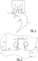
- upper tool 1 ( figure 1 ) and a lower tool 2 ( figure 8 ).
- Upper tool 1 is attached here in an upper clamping beam 3 which is in turn mounted on a (schematically shown) upper frame 47 of the apparatus, while lower tool 2 is received in a lower clamping beam 4 which is likewise mounted on a lower frame 48 of the apparatus.
- Upper and lower clamping beams 3, 4 can otherwise also form an integral part of respectively upper frame 47 and lower frame 48.
- the apparatus which is also known as a press brake, is provided with a drive whereby the upper and lower frames 47, 48 with the upper and lower clamping beams 3, 4 mounted thereon can be moved toward each other with force in order to bend a piece of plate material placed between lower tool 2 and upper tool 1 to a desired angle.
- Lower frame 48 with lower beam 4 and lower tool 2 will in many cases be held in place here, and upper frame 47 with upper beam 3 and upper tool 1 will be moved downward.
- Upper tool 1 comprises a mounting part 5 configured to be received in a receiving space 6 of upper beam 3 ( figure 3 ).
- This receiving space 6 takes the form of an elongate recess or groove extending over the whole length of upper beam 3.
- the tool comprises a shaping part 7 extending in the direction of the lower beam from mounting part 5.
- This shaping part 7 has a roughly C-shaped cross-section here and ends in a bending edge 8.
- Tool 1 has two shoulders 9 on either side of mounting part 5 which during use come into engagement with support surfaces 10 on the underside of upper beam 3 so as to transmit the pressure forces in evenly distributed manner into tool 1.
- lower tool 2 comprises two mounting parts 11 configured to be received in a receiving space 12 in lower beam 4 of the apparatus ( figure 10 ).
- This receiving space 12 is also an elongate recess or groove and extends over the length of lower beam 4.
- Lower tool 2 additionally comprises a shaping part 13 provided in the shown embodiment with a substantially V-shaped groove 14 directed toward upper tool 1.
- Lower tool 2 further has two shoulders 15 extending on either side of a groove 16 in which the mounting parts 11 are fixed. During use of the apparatus and the tool these shoulders 15 rest on support surfaces 17 of lower beam 4 of the apparatus.
- lower tool 2 could also have a mounting part formed integrally with the rest of the tool.
- the apparatus and tools 1, 2 are particularly intended for the purpose of shaping relatively thick metal plate with a material thickness in the order of 10 mm or more. This results in tools 1, 2 taking a relatively large and heavy form.
- Tools which are suitable for bending such thick metal plates often weigh in the order of 200 kg per running metre.
- These bending tools are generally supplied in different length sizes for the purpose of shaping materials with varying dimensions.
- a plurality of tools can for instance be placed adjacently of each other here in the press brake.
- relatively short tools of for instance 50 cm already have a weight of about 100 kg and cannot therefore be handled by a user without auxiliary means.
- the invention therefore provides displacing means with which tools 1, 2 can be displaced in the respective receiving spaces 6, 12.
- the displacement is envisaged here in the longitudinal direction of receiving spaces 6, 12, so parallel to the bending edge 8 and groove 14 of tools 1, 2.
- the displacing means comprise displacing members 18, 32 protruding from the mounting part 5, 11 of the associated upper or lower tool 1, 2.
- these displacing members 18, 32 are each mounted rotatably in the corresponding mounting part 5, 11 and thus form rollers or wheels which engage on a wall part 45, 37 in the associated receiving space 6, 12.
- Displacing members 18 of upper tool 1 are formed here by the outer ends of a rod 24 which is received in a through-bore 22 in mounting part 5 ( figures 6, 7 ). These outer ends 18 protrude outside side walls 46 of the mounting part.
- a bearing 26 Arranged around a middle part of rod 24 is a bearing 26 which is retained by a flange 25 of rod 24. Flange 25 is in turn retained by a ring 27 which is pressed into a groove 28.
- Bore 22 has a narrowed portion 23 in which rod 24 is rotatable in closely-fitting manner. The bore is sealed by a gasket ring 29.
- upper tool 1 is provided with two sets of displacing members 18 arranged close to the outer ends ( figure 2 ).
- displacing members 18 protrude outside side walls 46 of mounting part 5 of upper tool 1, between shoulders 9 and recesses 20 to be discussed below.
- the receiving space 6 is provided with two side chambers 19, likewise extending over the length of upper beam 3.
- displacing members 18 move over bottoms 45 of side chambers 19 on either side of main recess 6.
- the height of side chambers 19 is greater than the diameter of displacing members 18, while the depth of side chambers 19 is greater than the distance the displacing members 18 protrude from side walls 46 of mounting part 5.
- mounting part 5 can here touch a side wall of recess 6, or the upper side of the mounting part can come into contact with the upper wall of recess 6. In this situation mounting part 5 is pressed so far upward that displacing members 18 have moved clear of wall part 45, although not so far that they could come into contact with any other wall of side chambers 19. Displacing members 18 are thus not loaded.
- lower tool 2 has two mounting parts 11 arranged spaced apart in longitudinal direction.
- the mounting parts 11 are connected releasably to shaping part 13 by means of bolts 30 running through holes 31.
- Each mounting part 11 is provided here with two displacing members 32 which are likewise arranged spaced apart in longitudinal direction.
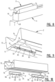
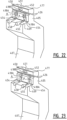
- Each displacing member 32 takes the form of a roller arranged rotatably on a shaft 34 via a bearing 33. Displacing members 32 are received in recesses 35 in mounting part 11 and each protrude to some extent below the bottom surface 36 thereof.
- bottom 37 of recess 12 is movable such that it comes to lie clear of displacing members 32.
- the movable bottom 37 rests via a coupling part 38 on a sealing strip 39 functioning as piston.
- This sealing strip 39 is accommodated movably in an opening 40 in the upper side of an elongate pneumatic reservoir 41 which is arranged in a recess 42 in lower beam 4.
- the movement of sealing strip 39 is bounded by the dimensions of another recess 44 in lower beam 4.
- Activation of a pneumatic system enables pressure to be applied to reservoir 41, whereby sealing strip 39 is urged upward and bottom 37 is moved upward until it comes into engagement with displacing members 32 ( figures 12 , 14 ). If on the other hand the pressure is removed from reservoir 41, sealing strip 39 then drops back into opening 40 under the influence of the weight of bottom 37 and coupling part 38.
- Movable bottom 37 hereby drops until it comes to rest on an outer edge 43 of receiving space 12. In this position the displacing members 32 lie clear of bottom 37 ( figures 13 , 15 ). Bottom 37 could otherwise also be movable hydraulically, or even mechanically, instead of pneumatically.
- the above described upper tool 1 is of the type known as a "Wila style" tool, the protruding mounting part 5 of which has a specific form which ensures that the tool can be positioned and clamped quickly and easily.
- the invention can however also be applied in other types of tool.
- Figure 16 thus shows a so-called "American style" upper tool 101, the mounting part 105 of which is provided close to its free outer end with displacing members 118 protruding from side walls 146.
- These displacing members 118 are received here in two side chambers 119 of the T-shaped receiving space 106 in upper beam 103 and are moved over the bottoms 145 of these side chambers 119 when tool 101 has to be positioned.
- tool 101 is otherwise clamped in upper beam 103, wherein shoulders 109 lie against support surfaces 110 and displacing members 118 lie clear of the walls of side chambers 119.
- a rod 979 protrudes from an end surface 977 of mounting part 905 ( figure 34 ).
- This rod 979 is provided with a bore 922 in which a shaft 924 is mounted.
- Mounted on the outer ends of this shaft 924 are two displacing members 918 which can in turn be moved through side chambers 919 of the T-shaped receiving space 906. It would also be possible in this variant to suffice with a single displacing member 918 on a side of rod 979.
- Figure 17 shows a "European style" upper tool 201 which is clamped in a receiving space 206 defined by an upper beam 203 with a narrowed underside and a separate clamping member 249.
- This upper tool is also provided with displacing members 218 on either side of mounting part 205, only one of which however protrudes outside side surface 246.
- the other displacing member 218 only lies clear on its underside, and thereby rolls over bottom 245 of a side chamber 219 formed in clamping member 249.
- Displacing members 218 are here also formed by the outer ends of a rod 224 which protrudes through a bore 222 in mounting part 205 and is mounted in a bearing 226.
- the mounting part 305 is provided with two types of displacing member 318A, 318B protruding on mutually opposite sides from side walls 346 ( figures 18-20 ).
- Displacing members 318A two of which are shown here, are each rotatable here about an axis A extending transversely of shaping direction W, so in the shown embodiment horizontally.
- the single displacing member 318B is on the other hand pivotable about an axis B extending in the shaping direction W of tool 301, so in the shown embodiment a vertical axis.
- the two displacing members 318A are arranged here between groove 320 and the "shoulder” 309 of tool 301, while the single displacing member 318B is placed close to end surface 377 of mounting part 305.
- the "shoulders" 309 do not engage with lower surfaces 310 of upper beam 303 during the clamping.
- Tool 301 instead supports in the clamped situation with its end surface 377 against an upper surface 378 of receiving space 306.
- Displacing members 318A are once again received in two through-bores 332 and mounting part 305, while the single displacing member 318B is received in an elongate recess 350 in mounting part 305.
- This displacing member 318B is rotatable around a shaft stub 351 placed in a bore 352 in the end surface of mounting part 305.
- the two displacing members 318A rotatable about horizontal axes A are again intended to roll over bottom 345 of a side chamber 319 of receiving space 306.
- Displacing member 318B rotatable about vertical axis B is on the other hand intended to roll along a side wall 353 of receiving space 306 ( figure 21 ).
- This arrangement of the displacing members is advantageous, since the centre of gravity of tool 301, which is also referred to as a "tub tool", lies in the shown embodiment quite far out of the line of mounting part 305. This is a result of the convex form of shaping part 307.
- each displacing member 418A rotatable about horizontal axes A are retractable into mounting part 405.
- Each displacing member 418A is for this purpose mounted rotatably via bearing 426 in a slide 454, which is in turn mounted slidably in a recess 455 extending in both mounting part 405 and, partially, in shoulder 409.
- Each slide 454 comprises an upper part 456 which supports bearing 426 and displacing member 418A, a middle part connected to a guide member 457 and a lower part 458 protruding outside the tool and functioning as operating member or pushbutton.
- Guide member 457 has a narrow shank which protrudes through an opening 462 and a widened head which cannot pass through this opening and functions as stop. This widened head is slidable in a bore 459 lying opposite recess 455. Slide 454 with displacing member 418A is biased to its protruding position by means of a biasing member 460 received in a chamber 461.
- Pressing operating member 458 presses slide 454 into recess 455 counter to the force of biasing member 460, whereby displacing member 418A comes to lie within the periphery of mounting part 405. In this position the mounting part 405 can be inserted into the receiving space (not shown here) of the apparatus.
- slide 454 is pressed outward again by biasing member 460 ( figure 24B ), whereby displacing member 418A once again engages in the side chamber of the receiving space in the above described manner.
- the mounting parts 511 in which displacing members 532 are mounted are for this purpose movable in the shaping direction relative to the rest of lower tool 502 ( figures 25, 26 ).
- Mounting part 511 is slidable in the shaping direction in groove 516 on the underside of lower tool 502.
- Formed in shaping part 513 of tool 502 is a bore 563 which extends from the bottom 564 of V-shaped groove 514 to groove 516.
- Received in this bore 563 is a control pin 530 with a head 565 on which a tool, for instance a socket wrench or a screwdriver, can engage and which has a narrowed threaded end 566.
- This threaded end 566 protrudes into hole 531 in mounting part 511 which is provided with internal screw thread.
- Mounting part 511 and shaping part 513 are further also provided with blind bores 568, 569 which lie mutually in line and in which a guide pin 567 is received.
- an alternative embodiment of lower tool 602 is provided with an operating mechanism which is accessible from the side of the tool ( figures 27-29 ).
- two stepped bores 668 are formed in each mounting part 611 which lie in line with blind bores 669 in shaping part 613 of lower tool 602.
- guide pins 667 Arranged in these bores are guide pins 667 which are screwed with their threaded ends into bores 669.
- These guide pins 667 have a thickened head which is movable through the widened part of bore 668 and which encloses a biasing member 672, for instance a helical spring.
- a bore 663 in which a control pin 630 is slidably received is further formed in shaping part 613 between bores 669. An outer end of this control pin 630 engages on the upper side of mounting part 611 while the other outer end is in engagement with a narrowed and eccentric middle part 671 of a horizontal operating rod 673.
- a pneumatic or a hydraulic operation could of course also be envisaged instead of the mechanical operation shown and described here for extending and retracting the displacing members.
- the mounting part 705 can thus be provided with one or more protruding displacing members 718A, while one or more displacing members 718B are additionally arranged on shaping part 707 of tool 701 ( figures 30-32 ).
- a similar solution could also be used in a lower tool, where one or more displacing members could be arranged in the shoulder(s) adjacently of the protruding mounting part, or even on the sides of the tool.
- the invention thus makes it possible with relatively simple means to clamp large and heavy tools, which are used to shape relatively thick metal plate, at a desired position in an apparatus or to remove them therefrom.
Landscapes
- Engineering & Computer Science (AREA)
- Mechanical Engineering (AREA)
- Bending Of Plates, Rods, And Pipes (AREA)
- Mounting, Exchange, And Manufacturing Of Dies (AREA)
- Machine Tool Units (AREA)
- Auxiliary Devices For Music (AREA)
Applications Claiming Priority (4)
| Application Number | Priority Date | Filing Date | Title |
|---|---|---|---|
| NL2009141 | 2012-07-06 | ||
| NL2009340A NL2009340C2 (nl) | 2012-07-06 | 2012-08-22 | In een werktuig verplaatsbaar gereedschap. |
| EP13756717.8A EP2869946B1 (de) | 2012-07-06 | 2013-07-08 | In einer vorrichtung bewegliches werkzeug |
| PCT/NL2013/050513 WO2014007640A1 (en) | 2012-07-06 | 2013-07-08 | Tool which is movable in an apparatus |
Related Parent Applications (1)
| Application Number | Title | Priority Date | Filing Date |
|---|---|---|---|
| EP13756717.8A Division EP2869946B1 (de) | 2012-07-06 | 2013-07-08 | In einer vorrichtung bewegliches werkzeug |
Publications (2)
| Publication Number | Publication Date |
|---|---|
| EP4464433A2 true EP4464433A2 (de) | 2024-11-20 |
| EP4464433A3 EP4464433A3 (de) | 2025-02-19 |
Family
ID=49111510
Family Applications (2)
| Application Number | Title | Priority Date | Filing Date |
|---|---|---|---|
| EP13756717.8A Active EP2869946B1 (de) | 2012-07-06 | 2013-07-08 | In einer vorrichtung bewegliches werkzeug |
| EP24198177.8A Pending EP4464433A3 (de) | 2012-07-06 | 2013-07-08 | In einem gerät bewegliches werkzeug |
Family Applications Before (1)
| Application Number | Title | Priority Date | Filing Date |
|---|---|---|---|
| EP13756717.8A Active EP2869946B1 (de) | 2012-07-06 | 2013-07-08 | In einer vorrichtung bewegliches werkzeug |
Country Status (8)
| Country | Link |
|---|---|
| US (1) | US10144049B2 (de) |
| EP (2) | EP2869946B1 (de) |
| JP (2) | JP6351583B2 (de) |
| CN (1) | CN104507596B (de) |
| ES (1) | ES2991686T3 (de) |
| NL (1) | NL2009340C2 (de) |
| PL (1) | PL2869946T3 (de) |
| WO (1) | WO2014007640A1 (de) |
Families Citing this family (13)
| Publication number | Priority date | Publication date | Assignee | Title |
|---|---|---|---|---|
| GB2481420B (en) * | 2010-06-23 | 2012-06-13 | Rolls Royce Plc | Press brake |
| AT516043B1 (de) * | 2014-11-12 | 2016-02-15 | Trumpf Maschinen Austria Gmbh | Biegepresse und Beschickungsvorrichtung für eine Biegepresse |
| US11338349B2 (en) * | 2015-07-29 | 2022-05-24 | Abb Schweiz Ag | Loading dies in a press |
| JP6604904B2 (ja) * | 2016-05-26 | 2019-11-13 | 大同特殊鋼株式会社 | 金型固定構造 |
| NL2018393B1 (nl) * | 2017-02-20 | 2018-09-17 | Wila Bv | Inrichting voor het inklemmen van een gereedschap en werkwijze voor het vervaardigen van een dergelijke inrichting |
| AT520541B1 (de) * | 2018-05-07 | 2019-05-15 | Trumpf Maschinen Austria Gmbh & Co Kg | Unterwerkzeug mit Reibreduktionsvorrichtung |
| AT521173B1 (de) | 2018-06-27 | 2019-11-15 | Trumpf Maschinen Austria Gmbh & Co Kg | Biegewerkzeug mit Distanzelement |
| AT521530B1 (de) | 2018-07-27 | 2020-04-15 | Trumpf Maschinen Austria Gmbh & Co Kg | Biegepresse und Verfahren zum Betreiben einer Biegepresse |
| JP2020032436A (ja) * | 2018-08-28 | 2020-03-05 | 安田技研株式会社 | プレスブレーキ用金型セット |
| JP2020163449A (ja) * | 2019-03-29 | 2020-10-08 | 株式会社アマダ | 肩受けタイプのダイ金型及び曲げ加工システム |
| CN111069424A (zh) * | 2020-01-10 | 2020-04-28 | 新多集团有限公司 | 一种门板折边机半自动换模装置 |
| US12383951B2 (en) * | 2020-09-17 | 2025-08-12 | Murata Machinery, Ltd. | Upper die and machining system |
| CN115382956B (zh) * | 2022-10-27 | 2023-01-31 | 扬州宇鑫智能科技有限公司 | 液压折弯机 |
Citations (3)
| Publication number | Priority date | Publication date | Assignee | Title |
|---|---|---|---|---|
| JPS57199523A (en) | 1982-05-28 | 1982-12-07 | Hitachi Ltd | Bending die holding device |
| US5146774A (en) | 1991-02-27 | 1992-09-15 | Uniflo Conveyor, Inc. | Lift mechanism for installation and removal of press brake dies |
| EP1864752A1 (de) | 2006-06-07 | 2007-12-12 | Wila B.V. | Datenaustauschsystem |
Family Cites Families (20)
| Publication number | Priority date | Publication date | Assignee | Title |
|---|---|---|---|---|
| JPS53132457A (en) * | 1977-04-26 | 1978-11-18 | Komatsu Mfg Co Ltd | Die exchanging device of presssbrake |
| JPH0491833A (ja) | 1990-08-06 | 1992-03-25 | Ndc Co Ltd | 円筒状すべり軸受の製造方法及びその装置 |
| NL9100034A (nl) | 1991-01-10 | 1992-08-03 | Wila Maschf Bv | Kantpersgereedschap, en een adaptor en een kantpers daarvoor. |
| JPH06182447A (ja) * | 1992-12-17 | 1994-07-05 | Amada Metrecs Co Ltd | 上金型固定装置 |
| TW365857U (en) * | 1994-05-17 | 1999-08-01 | Amada Metrecs Co | Upper tool and upper tool holder apparatus for press brake |
| JP2002134973A (ja) | 2000-10-19 | 2002-05-10 | Matsushita Electric Ind Co Ltd | ヒートシンク装置及び電子機器 |
| JP2002134673A (ja) * | 2000-10-26 | 2002-05-10 | Nec Yamaguchi Ltd | リ−ド成形装置 |
| US6467327B1 (en) * | 2001-08-15 | 2002-10-22 | Wilson Tool International, Inc. | Press brake tool and tool holder |
| JP2003211223A (ja) * | 2002-01-16 | 2003-07-29 | Amada Co Ltd | 曲げ加工装置 |
| JP4271010B2 (ja) * | 2003-10-31 | 2009-06-03 | 株式会社アマダ | プレスブレーキ用ダイホルダ装置 |
| DE60311270T2 (de) * | 2003-11-06 | 2007-07-19 | Cornelis Hendricus Liet | Biegepresse |
| US7021116B2 (en) * | 2003-12-19 | 2006-04-04 | Wilson Tool International, Inc. | Press brake tooling technology |
| US7204793B2 (en) * | 2005-03-17 | 2007-04-17 | Hedin Lagan Ab | Device for moving die tools and moulds in a press |
| PL1762310T3 (pl) * | 2005-09-13 | 2008-04-30 | Rolleri S P A | Urządzenie do szybkiego sprzęgania i rozprzęgania górnego narzędzia w prasie krawędziowej |
| US7168286B1 (en) * | 2005-10-29 | 2007-01-30 | Pelech Bruno J | Device and method for securing a punch tool to a ram portion of a press brake |
| US7634935B2 (en) * | 2006-10-05 | 2009-12-22 | Rolleri S.P.A. | Quick upper tool coupling and uncoupling device of a press brake |
| EP1980337B1 (de) * | 2007-04-13 | 2012-08-08 | Wila B.V. | Spannvorrichtung für Biegewerkzeuge |
| US8141408B2 (en) * | 2007-12-04 | 2012-03-27 | Mccauley Kirk Allen | Holder for press dies |
| CN101559455B (zh) * | 2008-04-18 | 2012-03-28 | 鸿富锦精密工业(深圳)有限公司 | 卷圆成型模具 |
| ES2892223T3 (es) * | 2008-11-11 | 2022-02-02 | Wila Bv | Dispositivo para sujetar una herramienta |
-
2012
- 2012-08-22 NL NL2009340A patent/NL2009340C2/nl active
-
2013
- 2013-07-08 ES ES13756717T patent/ES2991686T3/es active Active
- 2013-07-08 PL PL13756717.8T patent/PL2869946T3/pl unknown
- 2013-07-08 CN CN201380036023.1A patent/CN104507596B/zh active Active
- 2013-07-08 EP EP13756717.8A patent/EP2869946B1/de active Active
- 2013-07-08 US US14/407,641 patent/US10144049B2/en active Active
- 2013-07-08 WO PCT/NL2013/050513 patent/WO2014007640A1/en not_active Ceased
- 2013-07-08 EP EP24198177.8A patent/EP4464433A3/de active Pending
- 2013-07-08 JP JP2015520097A patent/JP6351583B2/ja active Active
-
2018
- 2018-03-19 JP JP2018051071A patent/JP6665216B2/ja active Active
Patent Citations (3)
| Publication number | Priority date | Publication date | Assignee | Title |
|---|---|---|---|---|
| JPS57199523A (en) | 1982-05-28 | 1982-12-07 | Hitachi Ltd | Bending die holding device |
| US5146774A (en) | 1991-02-27 | 1992-09-15 | Uniflo Conveyor, Inc. | Lift mechanism for installation and removal of press brake dies |
| EP1864752A1 (de) | 2006-06-07 | 2007-12-12 | Wila B.V. | Datenaustauschsystem |
Also Published As
| Publication number | Publication date |
|---|---|
| WO2014007640A1 (en) | 2014-01-09 |
| JP6665216B2 (ja) | 2020-03-13 |
| EP2869946B1 (de) | 2024-09-04 |
| EP2869946A1 (de) | 2015-05-13 |
| CN104507596B (zh) | 2017-05-31 |
| US20150165506A1 (en) | 2015-06-18 |
| US10144049B2 (en) | 2018-12-04 |
| JP2015521955A (ja) | 2015-08-03 |
| ES2991686T3 (es) | 2024-12-04 |
| NL2009340C2 (nl) | 2014-01-07 |
| JP2018134684A (ja) | 2018-08-30 |
| PL2869946T3 (pl) | 2025-02-24 |
| CN104507596A (zh) | 2015-04-08 |
| EP4464433A3 (de) | 2025-02-19 |
| JP6351583B2 (ja) | 2018-07-04 |
Similar Documents
| Publication | Publication Date | Title |
|---|---|---|
| EP4464433A2 (de) | In einem gerät bewegliches werkzeug | |
| US9908163B1 (en) | Metal plate bending apparatus and method | |
| US5782308A (en) | Quick clamping device for at least one tool of a machine tool | |
| WO2001039906A1 (en) | Safety tool for supporting and holding at least one interchangeable utensil, particularly on a press-bending machine | |
| EP1698408B1 (de) | Mit verriegelbarem Sicherungselement versehenes Werkzeug einer Abkantpresse | |
| EP1620213A1 (de) | Biegepressenwerkzeug | |
| US4369907A (en) | Punching and riveting machine | |
| US7596983B2 (en) | Press brake clamp incorporating tool-seating mechanism | |
| CA2604645A1 (en) | Press brake tool seating technology | |
| CN104325054B (zh) | 四鞍座冲压工具和锻压机 | |
| US7661288B2 (en) | Press brake tool safety key assemblies | |
| CN215966125U (zh) | 一种锻造操作机及锻压设备 | |
| US20170095988A1 (en) | C-frame press | |
| US5280715A (en) | Lifting arrangement and method | |
| US6178799B1 (en) | Forming press and method for shaping angle-section workpieces | |
| US9687896B2 (en) | Sheet metal brake press | |
| CN105500198B (zh) | 后轿半轴密封盖用固定装置 | |
| US20180126434A1 (en) | Method and machine for bending metal including locking mechanism for adjustable die | |
| US6575212B2 (en) | Adjustable height workstation | |
| EP1165264B1 (de) | Werkzeughaltevorrichtung für abkantbiegepressen | |
| CN110732820B (zh) | 焊接夹紧工装 | |
| US11752583B1 (en) | Workpiece locational positioner | |
| CN214162782U (zh) | 一种用于铁路货车组装自动定位的装置 | |
| EP1133368A1 (de) | Verriegelungseinrichtung zum festlegen eines werkzeugs an einer maschine |
Legal Events
| Date | Code | Title | Description |
|---|---|---|---|
| PUAI | Public reference made under article 153(3) epc to a published international application that has entered the european phase |
Free format text: ORIGINAL CODE: 0009012 |
|
| STAA | Information on the status of an ep patent application or granted ep patent |
Free format text: STATUS: THE APPLICATION HAS BEEN PUBLISHED |
|
| AC | Divisional application: reference to earlier application |
Ref document number: 2869946 Country of ref document: EP Kind code of ref document: P |
|
| AK | Designated contracting states |
Kind code of ref document: A2 Designated state(s): AL AT BE BG CH CY CZ DE DK EE ES FI FR GB GR HR HU IE IS IT LI LT LU LV MC MK MT NL NO PL PT RO RS SE SI SK SM TR |
|
| PUAL | Search report despatched |
Free format text: ORIGINAL CODE: 0009013 |
|
| AK | Designated contracting states |
Kind code of ref document: A3 Designated state(s): AL AT BE BG CH CY CZ DE DK EE ES FI FR GB GR HR HU IE IS IT LI LT LU LV MC MK MT NL NO PL PT RO RS SE SI SK SM TR |
|
| RIC1 | Information provided on ipc code assigned before grant |
Ipc: B21D 37/04 20060101ALI20250114BHEP Ipc: B21D 5/02 20060101AFI20250114BHEP |
|
| STAA | Information on the status of an ep patent application or granted ep patent |
Free format text: STATUS: REQUEST FOR EXAMINATION WAS MADE |
|
| 17P | Request for examination filed |
Effective date: 20250819 |