EP4448910B1 - Vakuumisolierte platte mit getter mit einer ti-al-v-kristallphase und herstellungsverfahren dafür - Google Patents
Vakuumisolierte platte mit getter mit einer ti-al-v-kristallphase und herstellungsverfahren dafür Download PDFInfo
- Publication number
- EP4448910B1 EP4448910B1 EP23821064.5A EP23821064A EP4448910B1 EP 4448910 B1 EP4448910 B1 EP 4448910B1 EP 23821064 A EP23821064 A EP 23821064A EP 4448910 B1 EP4448910 B1 EP 4448910B1
- Authority
- EP
- European Patent Office
- Prior art keywords
- layer
- getter
- main seal
- laser
- example embodiments
- Prior art date
- Legal status (The legal status is an assumption and is not a legal conclusion. Google has not performed a legal analysis and makes no representation as to the accuracy of the status listed.)
- Active
Links
Images


Classifications
-
- E—FIXED CONSTRUCTIONS
- E06—DOORS, WINDOWS, SHUTTERS, OR ROLLER BLINDS IN GENERAL; LADDERS
- E06B—FIXED OR MOVABLE CLOSURES FOR OPENINGS IN BUILDINGS, VEHICLES, FENCES OR LIKE ENCLOSURES IN GENERAL, e.g. DOORS, WINDOWS, BLINDS, GATES
- E06B3/00—Window sashes, door leaves, or like elements for closing wall or like openings; Layout of fixed or moving closures, e.g. windows in wall or like openings; Features of rigidly-mounted outer frames relating to the mounting of wing frames
- E06B3/66—Units comprising two or more parallel glass or like panes permanently secured together
- E06B3/6612—Evacuated glazing units
-
- B—PERFORMING OPERATIONS; TRANSPORTING
- B01—PHYSICAL OR CHEMICAL PROCESSES OR APPARATUS IN GENERAL
- B01J—CHEMICAL OR PHYSICAL PROCESSES, e.g. CATALYSIS OR COLLOID CHEMISTRY; THEIR RELEVANT APPARATUS
- B01J20/00—Solid sorbent compositions or filter aid compositions; Sorbents for chromatography; Processes for preparing, regenerating or reactivating thereof
- B01J20/02—Solid sorbent compositions or filter aid compositions; Sorbents for chromatography; Processes for preparing, regenerating or reactivating thereof comprising inorganic material
- B01J20/0203—Solid sorbent compositions or filter aid compositions; Sorbents for chromatography; Processes for preparing, regenerating or reactivating thereof comprising inorganic material comprising compounds of metals not provided for in B01J20/04
- B01J20/0211—Compounds of Ti, Zr, Hf
-
- B—PERFORMING OPERATIONS; TRANSPORTING
- B01—PHYSICAL OR CHEMICAL PROCESSES OR APPARATUS IN GENERAL
- B01J—CHEMICAL OR PHYSICAL PROCESSES, e.g. CATALYSIS OR COLLOID CHEMISTRY; THEIR RELEVANT APPARATUS
- B01J20/00—Solid sorbent compositions or filter aid compositions; Sorbents for chromatography; Processes for preparing, regenerating or reactivating thereof
- B01J20/02—Solid sorbent compositions or filter aid compositions; Sorbents for chromatography; Processes for preparing, regenerating or reactivating thereof comprising inorganic material
- B01J20/0203—Solid sorbent compositions or filter aid compositions; Sorbents for chromatography; Processes for preparing, regenerating or reactivating thereof comprising inorganic material comprising compounds of metals not provided for in B01J20/04
- B01J20/0214—Compounds of V, Nb, Ta
-
- B—PERFORMING OPERATIONS; TRANSPORTING
- B01—PHYSICAL OR CHEMICAL PROCESSES OR APPARATUS IN GENERAL
- B01J—CHEMICAL OR PHYSICAL PROCESSES, e.g. CATALYSIS OR COLLOID CHEMISTRY; THEIR RELEVANT APPARATUS
- B01J20/00—Solid sorbent compositions or filter aid compositions; Sorbents for chromatography; Processes for preparing, regenerating or reactivating thereof
- B01J20/02—Solid sorbent compositions or filter aid compositions; Sorbents for chromatography; Processes for preparing, regenerating or reactivating thereof comprising inorganic material
- B01J20/0203—Solid sorbent compositions or filter aid compositions; Sorbents for chromatography; Processes for preparing, regenerating or reactivating thereof comprising inorganic material comprising compounds of metals not provided for in B01J20/04
- B01J20/0248—Compounds of B, Al, Ga, In, Tl
-
- B—PERFORMING OPERATIONS; TRANSPORTING
- B23—MACHINE TOOLS; METAL-WORKING NOT OTHERWISE PROVIDED FOR
- B23K—SOLDERING OR UNSOLDERING; WELDING; CLADDING OR PLATING BY SOLDERING OR WELDING; CUTTING BY APPLYING HEAT LOCALLY, e.g. FLAME CUTTING; WORKING BY LASER BEAM
- B23K26/00—Working by laser beam, e.g. welding, cutting or boring
- B23K26/20—Bonding
- B23K26/206—Laser sealing
-
- B—PERFORMING OPERATIONS; TRANSPORTING
- B23—MACHINE TOOLS; METAL-WORKING NOT OTHERWISE PROVIDED FOR
- B23K—SOLDERING OR UNSOLDERING; WELDING; CLADDING OR PLATING BY SOLDERING OR WELDING; CUTTING BY APPLYING HEAT LOCALLY, e.g. FLAME CUTTING; WORKING BY LASER BEAM
- B23K26/00—Working by laser beam, e.g. welding, cutting or boring
- B23K26/20—Bonding
- B23K26/32—Bonding taking account of the properties of the material involved
- B23K26/324—Bonding taking account of the properties of the material involved involving non-metallic parts
-
- B—PERFORMING OPERATIONS; TRANSPORTING
- B32—LAYERED PRODUCTS
- B32B—LAYERED PRODUCTS, i.e. PRODUCTS BUILT-UP OF STRATA OF FLAT OR NON-FLAT, e.g. CELLULAR OR HONEYCOMB, FORM
- B32B17/00—Layered products essentially comprising sheet glass, or glass, slag, or like fibres
-
- B—PERFORMING OPERATIONS; TRANSPORTING
- B32—LAYERED PRODUCTS
- B32B—LAYERED PRODUCTS, i.e. PRODUCTS BUILT-UP OF STRATA OF FLAT OR NON-FLAT, e.g. CELLULAR OR HONEYCOMB, FORM
- B32B17/00—Layered products essentially comprising sheet glass, or glass, slag, or like fibres
- B32B17/06—Layered products essentially comprising sheet glass, or glass, slag, or like fibres comprising glass as the main or only constituent of a layer, next to another layer of a specific material
- B32B17/068—Layered products essentially comprising sheet glass, or glass, slag, or like fibres comprising glass as the main or only constituent of a layer, next to another layer of a specific material of particles
-
- B—PERFORMING OPERATIONS; TRANSPORTING
- B32—LAYERED PRODUCTS
- B32B—LAYERED PRODUCTS, i.e. PRODUCTS BUILT-UP OF STRATA OF FLAT OR NON-FLAT, e.g. CELLULAR OR HONEYCOMB, FORM
- B32B17/00—Layered products essentially comprising sheet glass, or glass, slag, or like fibres
- B32B17/06—Layered products essentially comprising sheet glass, or glass, slag, or like fibres comprising glass as the main or only constituent of a layer, next to another layer of a specific material
- B32B17/10—Layered products essentially comprising sheet glass, or glass, slag, or like fibres comprising glass as the main or only constituent of a layer, next to another layer of a specific material of synthetic resin
- B32B17/10005—Layered products essentially comprising sheet glass, or glass, slag, or like fibres comprising glass as the main or only constituent of a layer, next to another layer of a specific material of synthetic resin laminated safety glass or glazing
- B32B17/10009—Layered products essentially comprising sheet glass, or glass, slag, or like fibres comprising glass as the main or only constituent of a layer, next to another layer of a specific material of synthetic resin laminated safety glass or glazing characterized by the number, the constitution or treatment of glass sheets
- B32B17/10036—Layered products essentially comprising sheet glass, or glass, slag, or like fibres comprising glass as the main or only constituent of a layer, next to another layer of a specific material of synthetic resin laminated safety glass or glazing characterized by the number, the constitution or treatment of glass sheets comprising two outer glass sheets
-
- C—CHEMISTRY; METALLURGY
- C03—GLASS; MINERAL OR SLAG WOOL
- C03B—MANUFACTURE, SHAPING, OR SUPPLEMENTARY PROCESSES
- C03B23/00—Re-forming shaped glass
- C03B23/20—Uniting glass pieces by fusing without substantial reshaping
- C03B23/24—Making hollow glass sheets or bricks
- C03B23/245—Hollow glass sheets
-
- C—CHEMISTRY; METALLURGY
- C03—GLASS; MINERAL OR SLAG WOOL
- C03C—CHEMICAL COMPOSITION OF GLASSES, GLAZES OR VITREOUS ENAMELS; SURFACE TREATMENT OF GLASS; SURFACE TREATMENT OF FIBRES OR FILAMENTS MADE FROM GLASS, MINERALS OR SLAGS; JOINING GLASS TO GLASS OR OTHER MATERIALS
- C03C23/00—Other surface treatment of glass not in the form of fibres or filaments
- C03C23/0005—Other surface treatment of glass not in the form of fibres or filaments by irradiation
- C03C23/0025—Other surface treatment of glass not in the form of fibres or filaments by irradiation by a laser beam
-
- C—CHEMISTRY; METALLURGY
- C03—GLASS; MINERAL OR SLAG WOOL
- C03C—CHEMICAL COMPOSITION OF GLASSES, GLAZES OR VITREOUS ENAMELS; SURFACE TREATMENT OF GLASS; SURFACE TREATMENT OF FIBRES OR FILAMENTS MADE FROM GLASS, MINERALS OR SLAGS; JOINING GLASS TO GLASS OR OTHER MATERIALS
- C03C23/00—Other surface treatment of glass not in the form of fibres or filaments
- C03C23/007—Other surface treatment of glass not in the form of fibres or filaments by thermal treatment
-
- C—CHEMISTRY; METALLURGY
- C03—GLASS; MINERAL OR SLAG WOOL
- C03C—CHEMICAL COMPOSITION OF GLASSES, GLAZES OR VITREOUS ENAMELS; SURFACE TREATMENT OF GLASS; SURFACE TREATMENT OF FIBRES OR FILAMENTS MADE FROM GLASS, MINERALS OR SLAGS; JOINING GLASS TO GLASS OR OTHER MATERIALS
- C03C27/00—Joining pieces of glass to pieces of other inorganic material; Joining glass to glass other than by fusing
- C03C27/04—Joining glass to metal by means of an interlayer
- C03C27/042—Joining glass to metal by means of an interlayer consisting of a combination of materials selected from glass, glass-ceramic or ceramic material with metals, metal oxides or metal salts
- C03C27/044—Joining glass to metal by means of an interlayer consisting of a combination of materials selected from glass, glass-ceramic or ceramic material with metals, metal oxides or metal salts of glass, glass-ceramic or ceramic material only
-
- C—CHEMISTRY; METALLURGY
- C03—GLASS; MINERAL OR SLAG WOOL
- C03C—CHEMICAL COMPOSITION OF GLASSES, GLAZES OR VITREOUS ENAMELS; SURFACE TREATMENT OF GLASS; SURFACE TREATMENT OF FIBRES OR FILAMENTS MADE FROM GLASS, MINERALS OR SLAGS; JOINING GLASS TO GLASS OR OTHER MATERIALS
- C03C27/00—Joining pieces of glass to pieces of other inorganic material; Joining glass to glass other than by fusing
- C03C27/06—Joining glass to glass by processes other than fusing
- C03C27/08—Joining glass to glass by processes other than fusing with the aid of intervening metal
-
- C—CHEMISTRY; METALLURGY
- C03—GLASS; MINERAL OR SLAG WOOL
- C03C—CHEMICAL COMPOSITION OF GLASSES, GLAZES OR VITREOUS ENAMELS; SURFACE TREATMENT OF GLASS; SURFACE TREATMENT OF FIBRES OR FILAMENTS MADE FROM GLASS, MINERALS OR SLAGS; JOINING GLASS TO GLASS OR OTHER MATERIALS
- C03C27/00—Joining pieces of glass to pieces of other inorganic material; Joining glass to glass other than by fusing
- C03C27/06—Joining glass to glass by processes other than fusing
- C03C27/10—Joining glass to glass by processes other than fusing with the aid of adhesive specially adapted for that purpose
-
- C—CHEMISTRY; METALLURGY
- C03—GLASS; MINERAL OR SLAG WOOL
- C03C—CHEMICAL COMPOSITION OF GLASSES, GLAZES OR VITREOUS ENAMELS; SURFACE TREATMENT OF GLASS; SURFACE TREATMENT OF FIBRES OR FILAMENTS MADE FROM GLASS, MINERALS OR SLAGS; JOINING GLASS TO GLASS OR OTHER MATERIALS
- C03C3/00—Glass compositions
- C03C3/04—Glass compositions containing silica
- C03C3/062—Glass compositions containing silica with less than 40% silica by weight
- C03C3/064—Glass compositions containing silica with less than 40% silica by weight containing boron
- C03C3/066—Glass compositions containing silica with less than 40% silica by weight containing boron containing zinc
-
- C—CHEMISTRY; METALLURGY
- C03—GLASS; MINERAL OR SLAG WOOL
- C03C—CHEMICAL COMPOSITION OF GLASSES, GLAZES OR VITREOUS ENAMELS; SURFACE TREATMENT OF GLASS; SURFACE TREATMENT OF FIBRES OR FILAMENTS MADE FROM GLASS, MINERALS OR SLAGS; JOINING GLASS TO GLASS OR OTHER MATERIALS
- C03C3/00—Glass compositions
- C03C3/12—Silica-free oxide glass compositions
- C03C3/122—Silica-free oxide glass compositions containing oxides of As, Sb, Bi, Mo, W, V, Te as glass formers
-
- C—CHEMISTRY; METALLURGY
- C03—GLASS; MINERAL OR SLAG WOOL
- C03C—CHEMICAL COMPOSITION OF GLASSES, GLAZES OR VITREOUS ENAMELS; SURFACE TREATMENT OF GLASS; SURFACE TREATMENT OF FIBRES OR FILAMENTS MADE FROM GLASS, MINERALS OR SLAGS; JOINING GLASS TO GLASS OR OTHER MATERIALS
- C03C3/00—Glass compositions
- C03C3/12—Silica-free oxide glass compositions
- C03C3/14—Silica-free oxide glass compositions containing boron
-
- C—CHEMISTRY; METALLURGY
- C03—GLASS; MINERAL OR SLAG WOOL
- C03C—CHEMICAL COMPOSITION OF GLASSES, GLAZES OR VITREOUS ENAMELS; SURFACE TREATMENT OF GLASS; SURFACE TREATMENT OF FIBRES OR FILAMENTS MADE FROM GLASS, MINERALS OR SLAGS; JOINING GLASS TO GLASS OR OTHER MATERIALS
- C03C4/00—Compositions for glass with special properties
- C03C4/0071—Compositions for glass with special properties for laserable glass
-
- C—CHEMISTRY; METALLURGY
- C03—GLASS; MINERAL OR SLAG WOOL
- C03C—CHEMICAL COMPOSITION OF GLASSES, GLAZES OR VITREOUS ENAMELS; SURFACE TREATMENT OF GLASS; SURFACE TREATMENT OF FIBRES OR FILAMENTS MADE FROM GLASS, MINERALS OR SLAGS; JOINING GLASS TO GLASS OR OTHER MATERIALS
- C03C8/00—Enamels; Glazes; Fusion seal compositions being frit compositions having non-frit additions
- C03C8/02—Frit compositions, i.e. in a powdered or comminuted form
- C03C8/04—Frit compositions, i.e. in a powdered or comminuted form containing zinc
-
- C—CHEMISTRY; METALLURGY
- C03—GLASS; MINERAL OR SLAG WOOL
- C03C—CHEMICAL COMPOSITION OF GLASSES, GLAZES OR VITREOUS ENAMELS; SURFACE TREATMENT OF GLASS; SURFACE TREATMENT OF FIBRES OR FILAMENTS MADE FROM GLASS, MINERALS OR SLAGS; JOINING GLASS TO GLASS OR OTHER MATERIALS
- C03C8/00—Enamels; Glazes; Fusion seal compositions being frit compositions having non-frit additions
- C03C8/22—Enamels; Glazes; Fusion seal compositions being frit compositions having non-frit additions containing two or more distinct frits having different compositions
-
- C—CHEMISTRY; METALLURGY
- C03—GLASS; MINERAL OR SLAG WOOL
- C03C—CHEMICAL COMPOSITION OF GLASSES, GLAZES OR VITREOUS ENAMELS; SURFACE TREATMENT OF GLASS; SURFACE TREATMENT OF FIBRES OR FILAMENTS MADE FROM GLASS, MINERALS OR SLAGS; JOINING GLASS TO GLASS OR OTHER MATERIALS
- C03C8/00—Enamels; Glazes; Fusion seal compositions being frit compositions having non-frit additions
- C03C8/24—Fusion seal compositions being frit compositions having non-frit additions, i.e. for use as seals between dissimilar materials, e.g. glass and metal; Glass solders
-
- C—CHEMISTRY; METALLURGY
- C04—CEMENTS; CONCRETE; ARTIFICIAL STONE; CERAMICS; REFRACTORIES
- C04B—LIME, MAGNESIA; SLAG; CEMENTS; COMPOSITIONS THEREOF, e.g. MORTARS, CONCRETE OR LIKE BUILDING MATERIALS; ARTIFICIAL STONE; CERAMICS; REFRACTORIES; TREATMENT OF NATURAL STONE
- C04B35/00—Shaped ceramic products characterised by their composition; Ceramics compositions; Processing powders of inorganic compounds preparatory to the manufacturing of ceramic products
- C04B35/01—Shaped ceramic products characterised by their composition; Ceramics compositions; Processing powders of inorganic compounds preparatory to the manufacturing of ceramic products based on oxide ceramics
- C04B35/453—Shaped ceramic products characterised by their composition; Ceramics compositions; Processing powders of inorganic compounds preparatory to the manufacturing of ceramic products based on oxide ceramics based on zinc, tin, or bismuth oxides or solid solutions thereof with other oxides, e.g. zincates, stannates or bismuthates
-
- C—CHEMISTRY; METALLURGY
- C04—CEMENTS; CONCRETE; ARTIFICIAL STONE; CERAMICS; REFRACTORIES
- C04B—LIME, MAGNESIA; SLAG; CEMENTS; COMPOSITIONS THEREOF, e.g. MORTARS, CONCRETE OR LIKE BUILDING MATERIALS; ARTIFICIAL STONE; CERAMICS; REFRACTORIES; TREATMENT OF NATURAL STONE
- C04B35/00—Shaped ceramic products characterised by their composition; Ceramics compositions; Processing powders of inorganic compounds preparatory to the manufacturing of ceramic products
- C04B35/01—Shaped ceramic products characterised by their composition; Ceramics compositions; Processing powders of inorganic compounds preparatory to the manufacturing of ceramic products based on oxide ceramics
- C04B35/495—Shaped ceramic products characterised by their composition; Ceramics compositions; Processing powders of inorganic compounds preparatory to the manufacturing of ceramic products based on oxide ceramics based on vanadium, niobium, tantalum, molybdenum or tungsten oxides or solid solutions thereof with other oxides, e.g. vanadates, niobates, tantalates, molybdates or tungstates
-
- C—CHEMISTRY; METALLURGY
- C04—CEMENTS; CONCRETE; ARTIFICIAL STONE; CERAMICS; REFRACTORIES
- C04B—LIME, MAGNESIA; SLAG; CEMENTS; COMPOSITIONS THEREOF, e.g. MORTARS, CONCRETE OR LIKE BUILDING MATERIALS; ARTIFICIAL STONE; CERAMICS; REFRACTORIES; TREATMENT OF NATURAL STONE
- C04B35/00—Shaped ceramic products characterised by their composition; Ceramics compositions; Processing powders of inorganic compounds preparatory to the manufacturing of ceramic products
- C04B35/515—Shaped ceramic products characterised by their composition; Ceramics compositions; Processing powders of inorganic compounds preparatory to the manufacturing of ceramic products based on non-oxide ceramics
- C04B35/547—Shaped ceramic products characterised by their composition; Ceramics compositions; Processing powders of inorganic compounds preparatory to the manufacturing of ceramic products based on non-oxide ceramics based on sulfides or selenides or tellurides
-
- C—CHEMISTRY; METALLURGY
- C04—CEMENTS; CONCRETE; ARTIFICIAL STONE; CERAMICS; REFRACTORIES
- C04B—LIME, MAGNESIA; SLAG; CEMENTS; COMPOSITIONS THEREOF, e.g. MORTARS, CONCRETE OR LIKE BUILDING MATERIALS; ARTIFICIAL STONE; CERAMICS; REFRACTORIES; TREATMENT OF NATURAL STONE
- C04B35/00—Shaped ceramic products characterised by their composition; Ceramics compositions; Processing powders of inorganic compounds preparatory to the manufacturing of ceramic products
- C04B35/622—Forming processes; Processing powders of inorganic compounds preparatory to the manufacturing of ceramic products
- C04B35/64—Burning or sintering processes
-
- E—FIXED CONSTRUCTIONS
- E06—DOORS, WINDOWS, SHUTTERS, OR ROLLER BLINDS IN GENERAL; LADDERS
- E06B—FIXED OR MOVABLE CLOSURES FOR OPENINGS IN BUILDINGS, VEHICLES, FENCES OR LIKE ENCLOSURES IN GENERAL, e.g. DOORS, WINDOWS, BLINDS, GATES
- E06B3/00—Window sashes, door leaves, or like elements for closing wall or like openings; Layout of fixed or moving closures, e.g. windows in wall or like openings; Features of rigidly-mounted outer frames relating to the mounting of wing frames
- E06B3/66—Units comprising two or more parallel glass or like panes permanently secured together
- E06B3/6621—Units comprising two or more parallel glass or like panes permanently secured together with special provisions for fitting in window frames or to adjacent units; Separate edge protecting strips
-
- E—FIXED CONSTRUCTIONS
- E06—DOORS, WINDOWS, SHUTTERS, OR ROLLER BLINDS IN GENERAL; LADDERS
- E06B—FIXED OR MOVABLE CLOSURES FOR OPENINGS IN BUILDINGS, VEHICLES, FENCES OR LIKE ENCLOSURES IN GENERAL, e.g. DOORS, WINDOWS, BLINDS, GATES
- E06B3/00—Window sashes, door leaves, or like elements for closing wall or like openings; Layout of fixed or moving closures, e.g. windows in wall or like openings; Features of rigidly-mounted outer frames relating to the mounting of wing frames
- E06B3/66—Units comprising two or more parallel glass or like panes permanently secured together
- E06B3/663—Elements for spacing panes
- E06B3/66304—Discrete spacing elements, e.g. for evacuated glazing units
-
- E—FIXED CONSTRUCTIONS
- E06—DOORS, WINDOWS, SHUTTERS, OR ROLLER BLINDS IN GENERAL; LADDERS
- E06B—FIXED OR MOVABLE CLOSURES FOR OPENINGS IN BUILDINGS, VEHICLES, FENCES OR LIKE ENCLOSURES IN GENERAL, e.g. DOORS, WINDOWS, BLINDS, GATES
- E06B3/00—Window sashes, door leaves, or like elements for closing wall or like openings; Layout of fixed or moving closures, e.g. windows in wall or like openings; Features of rigidly-mounted outer frames relating to the mounting of wing frames
- E06B3/66—Units comprising two or more parallel glass or like panes permanently secured together
- E06B3/663—Elements for spacing panes
- E06B3/66309—Section members positioned at the edges of the glazing unit
- E06B3/66333—Section members positioned at the edges of the glazing unit of unusual substances, e.g. wood or other fibrous materials, glass or other transparent materials
-
- E—FIXED CONSTRUCTIONS
- E06—DOORS, WINDOWS, SHUTTERS, OR ROLLER BLINDS IN GENERAL; LADDERS
- E06B—FIXED OR MOVABLE CLOSURES FOR OPENINGS IN BUILDINGS, VEHICLES, FENCES OR LIKE ENCLOSURES IN GENERAL, e.g. DOORS, WINDOWS, BLINDS, GATES
- E06B3/00—Window sashes, door leaves, or like elements for closing wall or like openings; Layout of fixed or moving closures, e.g. windows in wall or like openings; Features of rigidly-mounted outer frames relating to the mounting of wing frames
- E06B3/66—Units comprising two or more parallel glass or like panes permanently secured together
- E06B3/663—Elements for spacing panes
- E06B3/66309—Section members positioned at the edges of the glazing unit
- E06B3/66342—Section members positioned at the edges of the glazing unit characterised by their sealed connection to the panes
- E06B3/66357—Soldered connections or the like
-
- E—FIXED CONSTRUCTIONS
- E06—DOORS, WINDOWS, SHUTTERS, OR ROLLER BLINDS IN GENERAL; LADDERS
- E06B—FIXED OR MOVABLE CLOSURES FOR OPENINGS IN BUILDINGS, VEHICLES, FENCES OR LIKE ENCLOSURES IN GENERAL, e.g. DOORS, WINDOWS, BLINDS, GATES
- E06B3/00—Window sashes, door leaves, or like elements for closing wall or like openings; Layout of fixed or moving closures, e.g. windows in wall or like openings; Features of rigidly-mounted outer frames relating to the mounting of wing frames
- E06B3/66—Units comprising two or more parallel glass or like panes permanently secured together
- E06B3/67—Units comprising two or more parallel glass or like panes permanently secured together characterised by additional arrangements or devices for heat or sound insulation or for controlled passage of light
- E06B3/6715—Units comprising two or more parallel glass or like panes permanently secured together characterised by additional arrangements or devices for heat or sound insulation or for controlled passage of light specially adapted for increased thermal insulation or for controlled passage of light
-
- E—FIXED CONSTRUCTIONS
- E06—DOORS, WINDOWS, SHUTTERS, OR ROLLER BLINDS IN GENERAL; LADDERS
- E06B—FIXED OR MOVABLE CLOSURES FOR OPENINGS IN BUILDINGS, VEHICLES, FENCES OR LIKE ENCLOSURES IN GENERAL, e.g. DOORS, WINDOWS, BLINDS, GATES
- E06B3/00—Window sashes, door leaves, or like elements for closing wall or like openings; Layout of fixed or moving closures, e.g. windows in wall or like openings; Features of rigidly-mounted outer frames relating to the mounting of wing frames
- E06B3/66—Units comprising two or more parallel glass or like panes permanently secured together
- E06B3/673—Assembling the units
- E06B3/67326—Assembling spacer elements with the panes
- E06B3/67334—Assembling spacer elements with the panes by soldering; Preparing the panes therefor
-
- E—FIXED CONSTRUCTIONS
- E06—DOORS, WINDOWS, SHUTTERS, OR ROLLER BLINDS IN GENERAL; LADDERS
- E06B—FIXED OR MOVABLE CLOSURES FOR OPENINGS IN BUILDINGS, VEHICLES, FENCES OR LIKE ENCLOSURES IN GENERAL, e.g. DOORS, WINDOWS, BLINDS, GATES
- E06B3/00—Window sashes, door leaves, or like elements for closing wall or like openings; Layout of fixed or moving closures, e.g. windows in wall or like openings; Features of rigidly-mounted outer frames relating to the mounting of wing frames
- E06B3/66—Units comprising two or more parallel glass or like panes permanently secured together
- E06B3/673—Assembling the units
- E06B3/67339—Working the edges of already assembled units
- E06B3/6736—Heat treatment
-
- E—FIXED CONSTRUCTIONS
- E06—DOORS, WINDOWS, SHUTTERS, OR ROLLER BLINDS IN GENERAL; LADDERS
- E06B—FIXED OR MOVABLE CLOSURES FOR OPENINGS IN BUILDINGS, VEHICLES, FENCES OR LIKE ENCLOSURES IN GENERAL, e.g. DOORS, WINDOWS, BLINDS, GATES
- E06B3/00—Window sashes, door leaves, or like elements for closing wall or like openings; Layout of fixed or moving closures, e.g. windows in wall or like openings; Features of rigidly-mounted outer frames relating to the mounting of wing frames
- E06B3/66—Units comprising two or more parallel glass or like panes permanently secured together
- E06B3/677—Evacuating or filling the gap between the panes ; Equilibration of inside and outside pressure; Preventing condensation in the gap between the panes; Cleaning the gap between the panes
-
- F—MECHANICAL ENGINEERING; LIGHTING; HEATING; WEAPONS; BLASTING
- F16—ENGINEERING ELEMENTS AND UNITS; GENERAL MEASURES FOR PRODUCING AND MAINTAINING EFFECTIVE FUNCTIONING OF MACHINES OR INSTALLATIONS; THERMAL INSULATION IN GENERAL
- F16J—PISTONS; CYLINDERS; SEALINGS
- F16J15/00—Sealings
- F16J15/02—Sealings between relatively-stationary surfaces
- F16J15/06—Sealings between relatively-stationary surfaces with solid packing compressed between sealing surfaces
- F16J15/062—Sealings between relatively-stationary surfaces with solid packing compressed between sealing surfaces characterised by the geometry of the seat
-
- B—PERFORMING OPERATIONS; TRANSPORTING
- B23—MACHINE TOOLS; METAL-WORKING NOT OTHERWISE PROVIDED FOR
- B23K—SOLDERING OR UNSOLDERING; WELDING; CLADDING OR PLATING BY SOLDERING OR WELDING; CUTTING BY APPLYING HEAT LOCALLY, e.g. FLAME CUTTING; WORKING BY LASER BEAM
- B23K2103/00—Materials to be soldered, welded or cut
- B23K2103/50—Inorganic material, e.g. metals, not provided for in B23K2103/02 – B23K2103/26
- B23K2103/52—Ceramics
-
- B—PERFORMING OPERATIONS; TRANSPORTING
- B23—MACHINE TOOLS; METAL-WORKING NOT OTHERWISE PROVIDED FOR
- B23K—SOLDERING OR UNSOLDERING; WELDING; CLADDING OR PLATING BY SOLDERING OR WELDING; CUTTING BY APPLYING HEAT LOCALLY, e.g. FLAME CUTTING; WORKING BY LASER BEAM
- B23K2103/00—Materials to be soldered, welded or cut
- B23K2103/50—Inorganic material, e.g. metals, not provided for in B23K2103/02 – B23K2103/26
- B23K2103/54—Glass
-
- B—PERFORMING OPERATIONS; TRANSPORTING
- B23—MACHINE TOOLS; METAL-WORKING NOT OTHERWISE PROVIDED FOR
- B23K—SOLDERING OR UNSOLDERING; WELDING; CLADDING OR PLATING BY SOLDERING OR WELDING; CUTTING BY APPLYING HEAT LOCALLY, e.g. FLAME CUTTING; WORKING BY LASER BEAM
- B23K26/00—Working by laser beam, e.g. welding, cutting or boring
- B23K26/50—Working by transmitting the laser beam through or within the workpiece
- B23K26/57—Working by transmitting the laser beam through or within the workpiece the laser beam entering a face of the workpiece from which it is transmitted through the workpiece material to work on a different workpiece face, e.g. for effecting removal, fusion splicing, modifying or reforming
-
- C—CHEMISTRY; METALLURGY
- C03—GLASS; MINERAL OR SLAG WOOL
- C03C—CHEMICAL COMPOSITION OF GLASSES, GLAZES OR VITREOUS ENAMELS; SURFACE TREATMENT OF GLASS; SURFACE TREATMENT OF FIBRES OR FILAMENTS MADE FROM GLASS, MINERALS OR SLAGS; JOINING GLASS TO GLASS OR OTHER MATERIALS
- C03C2204/00—Glasses, glazes or enamels with special properties
-
- C—CHEMISTRY; METALLURGY
- C03—GLASS; MINERAL OR SLAG WOOL
- C03C—CHEMICAL COMPOSITION OF GLASSES, GLAZES OR VITREOUS ENAMELS; SURFACE TREATMENT OF GLASS; SURFACE TREATMENT OF FIBRES OR FILAMENTS MADE FROM GLASS, MINERALS OR SLAGS; JOINING GLASS TO GLASS OR OTHER MATERIALS
- C03C2207/00—Compositions specially applicable for the manufacture of vitreous enamels
-
- C—CHEMISTRY; METALLURGY
- C04—CEMENTS; CONCRETE; ARTIFICIAL STONE; CERAMICS; REFRACTORIES
- C04B—LIME, MAGNESIA; SLAG; CEMENTS; COMPOSITIONS THEREOF, e.g. MORTARS, CONCRETE OR LIKE BUILDING MATERIALS; ARTIFICIAL STONE; CERAMICS; REFRACTORIES; TREATMENT OF NATURAL STONE
- C04B2235/00—Aspects relating to ceramic starting mixtures or sintered ceramic products
- C04B2235/02—Composition of constituents of the starting material or of secondary phases of the final product
- C04B2235/30—Constituents and secondary phases not being of a fibrous nature
- C04B2235/32—Metal oxides, mixed metal oxides, or oxide-forming salts thereof, e.g. carbonates, nitrates, (oxy)hydroxides, chlorides
- C04B2235/3205—Alkaline earth oxides or oxide forming salts thereof, e.g. beryllium oxide
- C04B2235/3206—Magnesium oxides or oxide-forming salts thereof
-
- C—CHEMISTRY; METALLURGY
- C04—CEMENTS; CONCRETE; ARTIFICIAL STONE; CERAMICS; REFRACTORIES
- C04B—LIME, MAGNESIA; SLAG; CEMENTS; COMPOSITIONS THEREOF, e.g. MORTARS, CONCRETE OR LIKE BUILDING MATERIALS; ARTIFICIAL STONE; CERAMICS; REFRACTORIES; TREATMENT OF NATURAL STONE
- C04B2235/00—Aspects relating to ceramic starting mixtures or sintered ceramic products
- C04B2235/02—Composition of constituents of the starting material or of secondary phases of the final product
- C04B2235/30—Constituents and secondary phases not being of a fibrous nature
- C04B2235/32—Metal oxides, mixed metal oxides, or oxide-forming salts thereof, e.g. carbonates, nitrates, (oxy)hydroxides, chlorides
- C04B2235/3205—Alkaline earth oxides or oxide forming salts thereof, e.g. beryllium oxide
- C04B2235/3208—Calcium oxide or oxide-forming salts thereof, e.g. lime
-
- C—CHEMISTRY; METALLURGY
- C04—CEMENTS; CONCRETE; ARTIFICIAL STONE; CERAMICS; REFRACTORIES
- C04B—LIME, MAGNESIA; SLAG; CEMENTS; COMPOSITIONS THEREOF, e.g. MORTARS, CONCRETE OR LIKE BUILDING MATERIALS; ARTIFICIAL STONE; CERAMICS; REFRACTORIES; TREATMENT OF NATURAL STONE
- C04B2235/00—Aspects relating to ceramic starting mixtures or sintered ceramic products
- C04B2235/02—Composition of constituents of the starting material or of secondary phases of the final product
- C04B2235/30—Constituents and secondary phases not being of a fibrous nature
- C04B2235/32—Metal oxides, mixed metal oxides, or oxide-forming salts thereof, e.g. carbonates, nitrates, (oxy)hydroxides, chlorides
- C04B2235/3205—Alkaline earth oxides or oxide forming salts thereof, e.g. beryllium oxide
- C04B2235/3213—Strontium oxides or oxide-forming salts thereof
-
- C—CHEMISTRY; METALLURGY
- C04—CEMENTS; CONCRETE; ARTIFICIAL STONE; CERAMICS; REFRACTORIES
- C04B—LIME, MAGNESIA; SLAG; CEMENTS; COMPOSITIONS THEREOF, e.g. MORTARS, CONCRETE OR LIKE BUILDING MATERIALS; ARTIFICIAL STONE; CERAMICS; REFRACTORIES; TREATMENT OF NATURAL STONE
- C04B2235/00—Aspects relating to ceramic starting mixtures or sintered ceramic products
- C04B2235/02—Composition of constituents of the starting material or of secondary phases of the final product
- C04B2235/30—Constituents and secondary phases not being of a fibrous nature
- C04B2235/32—Metal oxides, mixed metal oxides, or oxide-forming salts thereof, e.g. carbonates, nitrates, (oxy)hydroxides, chlorides
- C04B2235/3205—Alkaline earth oxides or oxide forming salts thereof, e.g. beryllium oxide
- C04B2235/3215—Barium oxides or oxide-forming salts thereof
-
- C—CHEMISTRY; METALLURGY
- C04—CEMENTS; CONCRETE; ARTIFICIAL STONE; CERAMICS; REFRACTORIES
- C04B—LIME, MAGNESIA; SLAG; CEMENTS; COMPOSITIONS THEREOF, e.g. MORTARS, CONCRETE OR LIKE BUILDING MATERIALS; ARTIFICIAL STONE; CERAMICS; REFRACTORIES; TREATMENT OF NATURAL STONE
- C04B2235/00—Aspects relating to ceramic starting mixtures or sintered ceramic products
- C04B2235/02—Composition of constituents of the starting material or of secondary phases of the final product
- C04B2235/30—Constituents and secondary phases not being of a fibrous nature
- C04B2235/32—Metal oxides, mixed metal oxides, or oxide-forming salts thereof, e.g. carbonates, nitrates, (oxy)hydroxides, chlorides
- C04B2235/3217—Aluminum oxide or oxide forming salts thereof, e.g. bauxite, alpha-alumina
-
- C—CHEMISTRY; METALLURGY
- C04—CEMENTS; CONCRETE; ARTIFICIAL STONE; CERAMICS; REFRACTORIES
- C04B—LIME, MAGNESIA; SLAG; CEMENTS; COMPOSITIONS THEREOF, e.g. MORTARS, CONCRETE OR LIKE BUILDING MATERIALS; ARTIFICIAL STONE; CERAMICS; REFRACTORIES; TREATMENT OF NATURAL STONE
- C04B2235/00—Aspects relating to ceramic starting mixtures or sintered ceramic products
- C04B2235/02—Composition of constituents of the starting material or of secondary phases of the final product
- C04B2235/30—Constituents and secondary phases not being of a fibrous nature
- C04B2235/32—Metal oxides, mixed metal oxides, or oxide-forming salts thereof, e.g. carbonates, nitrates, (oxy)hydroxides, chlorides
- C04B2235/3231—Refractory metal oxides, their mixed metal oxides, or oxide-forming salts thereof
- C04B2235/3232—Titanium oxides or titanates, e.g. rutile or anatase
-
- C—CHEMISTRY; METALLURGY
- C04—CEMENTS; CONCRETE; ARTIFICIAL STONE; CERAMICS; REFRACTORIES
- C04B—LIME, MAGNESIA; SLAG; CEMENTS; COMPOSITIONS THEREOF, e.g. MORTARS, CONCRETE OR LIKE BUILDING MATERIALS; ARTIFICIAL STONE; CERAMICS; REFRACTORIES; TREATMENT OF NATURAL STONE
- C04B2235/00—Aspects relating to ceramic starting mixtures or sintered ceramic products
- C04B2235/02—Composition of constituents of the starting material or of secondary phases of the final product
- C04B2235/30—Constituents and secondary phases not being of a fibrous nature
- C04B2235/32—Metal oxides, mixed metal oxides, or oxide-forming salts thereof, e.g. carbonates, nitrates, (oxy)hydroxides, chlorides
- C04B2235/3231—Refractory metal oxides, their mixed metal oxides, or oxide-forming salts thereof
- C04B2235/3239—Vanadium oxides, vanadates or oxide forming salts thereof, e.g. magnesium vanadate
-
- C—CHEMISTRY; METALLURGY
- C04—CEMENTS; CONCRETE; ARTIFICIAL STONE; CERAMICS; REFRACTORIES
- C04B—LIME, MAGNESIA; SLAG; CEMENTS; COMPOSITIONS THEREOF, e.g. MORTARS, CONCRETE OR LIKE BUILDING MATERIALS; ARTIFICIAL STONE; CERAMICS; REFRACTORIES; TREATMENT OF NATURAL STONE
- C04B2235/00—Aspects relating to ceramic starting mixtures or sintered ceramic products
- C04B2235/02—Composition of constituents of the starting material or of secondary phases of the final product
- C04B2235/30—Constituents and secondary phases not being of a fibrous nature
- C04B2235/32—Metal oxides, mixed metal oxides, or oxide-forming salts thereof, e.g. carbonates, nitrates, (oxy)hydroxides, chlorides
- C04B2235/3231—Refractory metal oxides, their mixed metal oxides, or oxide-forming salts thereof
- C04B2235/3244—Zirconium oxides, zirconates, hafnium oxides, hafnates, or oxide-forming salts thereof
-
- C—CHEMISTRY; METALLURGY
- C04—CEMENTS; CONCRETE; ARTIFICIAL STONE; CERAMICS; REFRACTORIES
- C04B—LIME, MAGNESIA; SLAG; CEMENTS; COMPOSITIONS THEREOF, e.g. MORTARS, CONCRETE OR LIKE BUILDING MATERIALS; ARTIFICIAL STONE; CERAMICS; REFRACTORIES; TREATMENT OF NATURAL STONE
- C04B2235/00—Aspects relating to ceramic starting mixtures or sintered ceramic products
- C04B2235/02—Composition of constituents of the starting material or of secondary phases of the final product
- C04B2235/30—Constituents and secondary phases not being of a fibrous nature
- C04B2235/32—Metal oxides, mixed metal oxides, or oxide-forming salts thereof, e.g. carbonates, nitrates, (oxy)hydroxides, chlorides
- C04B2235/3262—Manganese oxides, manganates, rhenium oxides or oxide-forming salts thereof, e.g. MnO
-
- C—CHEMISTRY; METALLURGY
- C04—CEMENTS; CONCRETE; ARTIFICIAL STONE; CERAMICS; REFRACTORIES
- C04B—LIME, MAGNESIA; SLAG; CEMENTS; COMPOSITIONS THEREOF, e.g. MORTARS, CONCRETE OR LIKE BUILDING MATERIALS; ARTIFICIAL STONE; CERAMICS; REFRACTORIES; TREATMENT OF NATURAL STONE
- C04B2235/00—Aspects relating to ceramic starting mixtures or sintered ceramic products
- C04B2235/02—Composition of constituents of the starting material or of secondary phases of the final product
- C04B2235/30—Constituents and secondary phases not being of a fibrous nature
- C04B2235/32—Metal oxides, mixed metal oxides, or oxide-forming salts thereof, e.g. carbonates, nitrates, (oxy)hydroxides, chlorides
- C04B2235/3298—Bismuth oxides, bismuthates or oxide forming salts thereof, e.g. zinc bismuthate
-
- C—CHEMISTRY; METALLURGY
- C04—CEMENTS; CONCRETE; ARTIFICIAL STONE; CERAMICS; REFRACTORIES
- C04B—LIME, MAGNESIA; SLAG; CEMENTS; COMPOSITIONS THEREOF, e.g. MORTARS, CONCRETE OR LIKE BUILDING MATERIALS; ARTIFICIAL STONE; CERAMICS; REFRACTORIES; TREATMENT OF NATURAL STONE
- C04B2235/00—Aspects relating to ceramic starting mixtures or sintered ceramic products
- C04B2235/02—Composition of constituents of the starting material or of secondary phases of the final product
- C04B2235/30—Constituents and secondary phases not being of a fibrous nature
- C04B2235/34—Non-metal oxides, non-metal mixed oxides, or salts thereof that form the non-metal oxides upon heating, e.g. carbonates, nitrates, (oxy)hydroxides, chlorides
- C04B2235/3409—Boron oxide, borates, boric acids, or oxide forming salts thereof, e.g. borax
-
- C—CHEMISTRY; METALLURGY
- C04—CEMENTS; CONCRETE; ARTIFICIAL STONE; CERAMICS; REFRACTORIES
- C04B—LIME, MAGNESIA; SLAG; CEMENTS; COMPOSITIONS THEREOF, e.g. MORTARS, CONCRETE OR LIKE BUILDING MATERIALS; ARTIFICIAL STONE; CERAMICS; REFRACTORIES; TREATMENT OF NATURAL STONE
- C04B2235/00—Aspects relating to ceramic starting mixtures or sintered ceramic products
- C04B2235/02—Composition of constituents of the starting material or of secondary phases of the final product
- C04B2235/30—Constituents and secondary phases not being of a fibrous nature
- C04B2235/34—Non-metal oxides, non-metal mixed oxides, or salts thereof that form the non-metal oxides upon heating, e.g. carbonates, nitrates, (oxy)hydroxides, chlorides
- C04B2235/3418—Silicon oxide, silicic acids or oxide forming salts thereof, e.g. silica sol, fused silica, silica fume, cristobalite, quartz or flint
-
- C—CHEMISTRY; METALLURGY
- C04—CEMENTS; CONCRETE; ARTIFICIAL STONE; CERAMICS; REFRACTORIES
- C04B—LIME, MAGNESIA; SLAG; CEMENTS; COMPOSITIONS THEREOF, e.g. MORTARS, CONCRETE OR LIKE BUILDING MATERIALS; ARTIFICIAL STONE; CERAMICS; REFRACTORIES; TREATMENT OF NATURAL STONE
- C04B2235/00—Aspects relating to ceramic starting mixtures or sintered ceramic products
- C04B2235/02—Composition of constituents of the starting material or of secondary phases of the final product
- C04B2235/30—Constituents and secondary phases not being of a fibrous nature
- C04B2235/34—Non-metal oxides, non-metal mixed oxides, or salts thereof that form the non-metal oxides upon heating, e.g. carbonates, nitrates, (oxy)hydroxides, chlorides
- C04B2235/3427—Silicates other than clay, e.g. water glass
- C04B2235/3463—Alumino-silicates other than clay, e.g. mullite
- C04B2235/3472—Alkali metal alumino-silicates other than clay, e.g. spodumene, alkali feldspars such as albite or orthoclase, micas such as muscovite, zeolites such as natrolite
-
- C—CHEMISTRY; METALLURGY
- C04—CEMENTS; CONCRETE; ARTIFICIAL STONE; CERAMICS; REFRACTORIES
- C04B—LIME, MAGNESIA; SLAG; CEMENTS; COMPOSITIONS THEREOF, e.g. MORTARS, CONCRETE OR LIKE BUILDING MATERIALS; ARTIFICIAL STONE; CERAMICS; REFRACTORIES; TREATMENT OF NATURAL STONE
- C04B2235/00—Aspects relating to ceramic starting mixtures or sintered ceramic products
- C04B2235/02—Composition of constituents of the starting material or of secondary phases of the final product
- C04B2235/30—Constituents and secondary phases not being of a fibrous nature
- C04B2235/34—Non-metal oxides, non-metal mixed oxides, or salts thereof that form the non-metal oxides upon heating, e.g. carbonates, nitrates, (oxy)hydroxides, chlorides
- C04B2235/3427—Silicates other than clay, e.g. water glass
- C04B2235/3463—Alumino-silicates other than clay, e.g. mullite
- C04B2235/3481—Alkaline earth metal alumino-silicates other than clay, e.g. cordierite, beryl, micas such as margarite, plagioclase feldspars such as anorthite, zeolites such as chabazite
-
- C—CHEMISTRY; METALLURGY
- C04—CEMENTS; CONCRETE; ARTIFICIAL STONE; CERAMICS; REFRACTORIES
- C04B—LIME, MAGNESIA; SLAG; CEMENTS; COMPOSITIONS THEREOF, e.g. MORTARS, CONCRETE OR LIKE BUILDING MATERIALS; ARTIFICIAL STONE; CERAMICS; REFRACTORIES; TREATMENT OF NATURAL STONE
- C04B2235/00—Aspects relating to ceramic starting mixtures or sintered ceramic products
- C04B2235/02—Composition of constituents of the starting material or of secondary phases of the final product
- C04B2235/30—Constituents and secondary phases not being of a fibrous nature
- C04B2235/38—Non-oxide ceramic constituents or additives
- C04B2235/3891—Silicides, e.g. molybdenum disilicide, iron silicide
-
- C—CHEMISTRY; METALLURGY
- C04—CEMENTS; CONCRETE; ARTIFICIAL STONE; CERAMICS; REFRACTORIES
- C04B—LIME, MAGNESIA; SLAG; CEMENTS; COMPOSITIONS THEREOF, e.g. MORTARS, CONCRETE OR LIKE BUILDING MATERIALS; ARTIFICIAL STONE; CERAMICS; REFRACTORIES; TREATMENT OF NATURAL STONE
- C04B2235/00—Aspects relating to ceramic starting mixtures or sintered ceramic products
- C04B2235/02—Composition of constituents of the starting material or of secondary phases of the final product
- C04B2235/30—Constituents and secondary phases not being of a fibrous nature
- C04B2235/40—Metallic constituents or additives not added as binding phase
- C04B2235/404—Refractory metals
-
- C—CHEMISTRY; METALLURGY
- C04—CEMENTS; CONCRETE; ARTIFICIAL STONE; CERAMICS; REFRACTORIES
- C04B—LIME, MAGNESIA; SLAG; CEMENTS; COMPOSITIONS THEREOF, e.g. MORTARS, CONCRETE OR LIKE BUILDING MATERIALS; ARTIFICIAL STONE; CERAMICS; REFRACTORIES; TREATMENT OF NATURAL STONE
- C04B2235/00—Aspects relating to ceramic starting mixtures or sintered ceramic products
- C04B2235/02—Composition of constituents of the starting material or of secondary phases of the final product
- C04B2235/30—Constituents and secondary phases not being of a fibrous nature
- C04B2235/44—Metal salt constituents or additives chosen for the nature of the anions, e.g. hydrides or acetylacetonate
- C04B2235/446—Sulfides, tellurides or selenides
-
- C—CHEMISTRY; METALLURGY
- C04—CEMENTS; CONCRETE; ARTIFICIAL STONE; CERAMICS; REFRACTORIES
- C04B—LIME, MAGNESIA; SLAG; CEMENTS; COMPOSITIONS THEREOF, e.g. MORTARS, CONCRETE OR LIKE BUILDING MATERIALS; ARTIFICIAL STONE; CERAMICS; REFRACTORIES; TREATMENT OF NATURAL STONE
- C04B2235/00—Aspects relating to ceramic starting mixtures or sintered ceramic products
- C04B2235/02—Composition of constituents of the starting material or of secondary phases of the final product
- C04B2235/30—Constituents and secondary phases not being of a fibrous nature
- C04B2235/44—Metal salt constituents or additives chosen for the nature of the anions, e.g. hydrides or acetylacetonate
- C04B2235/447—Phosphates or phosphites, e.g. orthophosphate or hypophosphite
-
- C—CHEMISTRY; METALLURGY
- C04—CEMENTS; CONCRETE; ARTIFICIAL STONE; CERAMICS; REFRACTORIES
- C04B—LIME, MAGNESIA; SLAG; CEMENTS; COMPOSITIONS THEREOF, e.g. MORTARS, CONCRETE OR LIKE BUILDING MATERIALS; ARTIFICIAL STONE; CERAMICS; REFRACTORIES; TREATMENT OF NATURAL STONE
- C04B2235/00—Aspects relating to ceramic starting mixtures or sintered ceramic products
- C04B2235/02—Composition of constituents of the starting material or of secondary phases of the final product
- C04B2235/50—Constituents or additives of the starting mixture chosen for their shape or used because of their shape or their physical appearance
- C04B2235/54—Particle size related information
- C04B2235/5418—Particle size related information expressed by the size of the particles or aggregates thereof
- C04B2235/5436—Particle size related information expressed by the size of the particles or aggregates thereof micrometer sized, i.e. from 1 to 100 micron
-
- C—CHEMISTRY; METALLURGY
- C04—CEMENTS; CONCRETE; ARTIFICIAL STONE; CERAMICS; REFRACTORIES
- C04B—LIME, MAGNESIA; SLAG; CEMENTS; COMPOSITIONS THEREOF, e.g. MORTARS, CONCRETE OR LIKE BUILDING MATERIALS; ARTIFICIAL STONE; CERAMICS; REFRACTORIES; TREATMENT OF NATURAL STONE
- C04B2235/00—Aspects relating to ceramic starting mixtures or sintered ceramic products
- C04B2235/02—Composition of constituents of the starting material or of secondary phases of the final product
- C04B2235/50—Constituents or additives of the starting mixture chosen for their shape or used because of their shape or their physical appearance
- C04B2235/54—Particle size related information
- C04B2235/5463—Particle size distributions
-
- C—CHEMISTRY; METALLURGY
- C04—CEMENTS; CONCRETE; ARTIFICIAL STONE; CERAMICS; REFRACTORIES
- C04B—LIME, MAGNESIA; SLAG; CEMENTS; COMPOSITIONS THEREOF, e.g. MORTARS, CONCRETE OR LIKE BUILDING MATERIALS; ARTIFICIAL STONE; CERAMICS; REFRACTORIES; TREATMENT OF NATURAL STONE
- C04B2235/00—Aspects relating to ceramic starting mixtures or sintered ceramic products
- C04B2235/65—Aspects relating to heat treatments of ceramic bodies such as green ceramics or pre-sintered ceramics, e.g. burning, sintering or melting processes
- C04B2235/66—Specific sintering techniques, e.g. centrifugal sintering
- C04B2235/665—Local sintering, e.g. laser sintering
-
- C—CHEMISTRY; METALLURGY
- C04—CEMENTS; CONCRETE; ARTIFICIAL STONE; CERAMICS; REFRACTORIES
- C04B—LIME, MAGNESIA; SLAG; CEMENTS; COMPOSITIONS THEREOF, e.g. MORTARS, CONCRETE OR LIKE BUILDING MATERIALS; ARTIFICIAL STONE; CERAMICS; REFRACTORIES; TREATMENT OF NATURAL STONE
- C04B2235/00—Aspects relating to ceramic starting mixtures or sintered ceramic products
- C04B2235/70—Aspects relating to sintered or melt-casted ceramic products
- C04B2235/74—Physical characteristics
- C04B2235/77—Density
-
- E—FIXED CONSTRUCTIONS
- E06—DOORS, WINDOWS, SHUTTERS, OR ROLLER BLINDS IN GENERAL; LADDERS
- E06B—FIXED OR MOVABLE CLOSURES FOR OPENINGS IN BUILDINGS, VEHICLES, FENCES OR LIKE ENCLOSURES IN GENERAL, e.g. DOORS, WINDOWS, BLINDS, GATES
- E06B3/00—Window sashes, door leaves, or like elements for closing wall or like openings; Layout of fixed or moving closures, e.g. windows in wall or like openings; Features of rigidly-mounted outer frames relating to the mounting of wing frames
- E06B3/66—Units comprising two or more parallel glass or like panes permanently secured together
- E06B3/663—Elements for spacing panes
- E06B3/66309—Section members positioned at the edges of the glazing unit
- E06B3/66333—Section members positioned at the edges of the glazing unit of unusual substances, e.g. wood or other fibrous materials, glass or other transparent materials
- E06B2003/66338—Section members positioned at the edges of the glazing unit of unusual substances, e.g. wood or other fibrous materials, glass or other transparent materials of glass
-
- E—FIXED CONSTRUCTIONS
- E06—DOORS, WINDOWS, SHUTTERS, OR ROLLER BLINDS IN GENERAL; LADDERS
- E06B—FIXED OR MOVABLE CLOSURES FOR OPENINGS IN BUILDINGS, VEHICLES, FENCES OR LIKE ENCLOSURES IN GENERAL, e.g. DOORS, WINDOWS, BLINDS, GATES
- E06B3/00—Window sashes, door leaves, or like elements for closing wall or like openings; Layout of fixed or moving closures, e.g. windows in wall or like openings; Features of rigidly-mounted outer frames relating to the mounting of wing frames
- E06B3/66—Units comprising two or more parallel glass or like panes permanently secured together
- E06B3/677—Evacuating or filling the gap between the panes ; Equilibration of inside and outside pressure; Preventing condensation in the gap between the panes; Cleaning the gap between the panes
- E06B3/6775—Evacuating or filling the gap during assembly
-
- Y—GENERAL TAGGING OF NEW TECHNOLOGICAL DEVELOPMENTS; GENERAL TAGGING OF CROSS-SECTIONAL TECHNOLOGIES SPANNING OVER SEVERAL SECTIONS OF THE IPC; TECHNICAL SUBJECTS COVERED BY FORMER USPC CROSS-REFERENCE ART COLLECTIONS [XRACs] AND DIGESTS
- Y02—TECHNOLOGIES OR APPLICATIONS FOR MITIGATION OR ADAPTATION AGAINST CLIMATE CHANGE
- Y02A—TECHNOLOGIES FOR ADAPTATION TO CLIMATE CHANGE
- Y02A30/00—Adapting or protecting infrastructure or their operation
- Y02A30/24—Structural elements or technologies for improving thermal insulation
- Y02A30/242—Slab shaped vacuum insulation
-
- Y—GENERAL TAGGING OF NEW TECHNOLOGICAL DEVELOPMENTS; GENERAL TAGGING OF CROSS-SECTIONAL TECHNOLOGIES SPANNING OVER SEVERAL SECTIONS OF THE IPC; TECHNICAL SUBJECTS COVERED BY FORMER USPC CROSS-REFERENCE ART COLLECTIONS [XRACs] AND DIGESTS
- Y02—TECHNOLOGIES OR APPLICATIONS FOR MITIGATION OR ADAPTATION AGAINST CLIMATE CHANGE
- Y02A—TECHNOLOGIES FOR ADAPTATION TO CLIMATE CHANGE
- Y02A30/00—Adapting or protecting infrastructure or their operation
- Y02A30/24—Structural elements or technologies for improving thermal insulation
- Y02A30/249—Glazing, e.g. vacuum glazing
-
- Y—GENERAL TAGGING OF NEW TECHNOLOGICAL DEVELOPMENTS; GENERAL TAGGING OF CROSS-SECTIONAL TECHNOLOGIES SPANNING OVER SEVERAL SECTIONS OF THE IPC; TECHNICAL SUBJECTS COVERED BY FORMER USPC CROSS-REFERENCE ART COLLECTIONS [XRACs] AND DIGESTS
- Y02—TECHNOLOGIES OR APPLICATIONS FOR MITIGATION OR ADAPTATION AGAINST CLIMATE CHANGE
- Y02B—CLIMATE CHANGE MITIGATION TECHNOLOGIES RELATED TO BUILDINGS, e.g. HOUSING, HOUSE APPLIANCES OR RELATED END-USER APPLICATIONS
- Y02B80/00—Architectural or constructional elements improving the thermal performance of buildings
- Y02B80/22—Glazing, e.g. vaccum glazing
Definitions
- Certain example embodiments are generally related to vacuum insulated devices such as vacuum insulating panels that may be used for windows or the like, and/or methods of making same.
- Vacuum insulated panels are known in the art.
- vacuum insulating panels are disclosed in U.S. Patent Nos. 2021/270084 A1 , 5,124,185 , 5,657,607 , 5,664,395 , 7,045,181 , 7,115,308 , 8,821,999 , 10,153,389 , and 11,124,450 .
- a vacuum insulating panel typically includes an outboard substrate, an inboard substrate, a hermetic edge seal, a sorption getter, a pump-out port, and spacers (e.g., pillars) sandwiched between at least the two substrates.
- the gap between the substrates may be at a pressure less than atmospheric pressure to provide insulating properties. Providing a vacuum in the space between the substrates reduces conduction and convection heat transport, and thus provides insulating properties.
- a vacuum insulating panel provides thermal insulation resistance by reducing convective energy between the two substrates, reducing conductive energy between the two transparent substrates, and reducing radiative energy with a low-emissivity (low-E) coating provided on one of the substrates.
- Vacuum insulating panels may be used in window applications (e.g., for commercial and/or residential windows), and/or for other applications such as commercial refrigeration and consumer appliance applications.
- the present invention concerns a vacuum insulating panel comprising: a first substrate; a second substrate; a plurality of spacers provided in a gap between at least the first and second substrates, wherein the gap is at pressure less than atmospheric pressure; a seal at least partially located between at least the first and second substrates; and a getter comprising getter material, wherein the getter material comprises a Ti-Al-V crystalline phase of approximately Al 3 V 0.333 Ti 0.666 .
- the present invention also concerns a method of making a vacuum insulating panel, the vacuum insulating panel comprising a first glass substrate, a second glass substrate, a plurality of spacers provided in a gap between at least the first and second glass substrates, a seal provided at least partially between at least the first and second glass substrates, and a getter; wherein the method comprises: providing the getter in a position exposed to the gap (e.g., in the gap), the getter comprising getter material; and laser treating and/or activating the getter in a manner causing the getter material to comprise a Ti-Al-V crystalline phase which was not present in the getter material prior to the laser treating and/or activating.
- the new crystalline phase may improve sorption of the getter in the vacuum insulating panel.
- Thermal heating methods and/or processes have been employed to sinter and/or fire ceramic sealing glass materials around the perimeter of the vacuum insulated glass panels.
- Such methods include batch oven systems using a combination of radiation and convective heating, in-line oven systems using a combination of radiation and convective heating, millimeter microwave selective perimeter heating, short wave infrared selective perimeter heating and laser perimeter heating. While each of these heating techniques may be used, for different type(s) of heating in various example embodiments, they do have one or more drawbacks in certain instances.
- Batch and in-line thermal processes that employ no selective heating techniques are sometimes not viable options for achieving tempered vacuum insulated glass units when the unit is exposed to high temperatures for long durations of time which significantly de-tempers the glass substrates, and/or may have high manufacturing costs due to low output and high utility costs related to thermal heating.
- Millimeter microwave involves high capital equipment costs, and long process cycle times, resulting in high manufacturing costs.
- Short wave infrared energy often cannot be directed to a narrow enough band around the perimeter of the glass, and thus can result in high levels of de-tempering of tempered glass at the perimeter which results in a high center to perimeter gradient and a lack of durability for the final panel, and resulting products have difficulty with safety impact tests (e.g., safety bag impact and/or fragmentation tests) and/or pass edge of glass compressive stress standards.
- safety impact tests e.g., safety bag impact and/or fragmentation tests
- Prior efforts to utilize laser heating of the perimeter seal have also been problematic.
- An example issue with prior laser heating is that extremely rapid heating and cooling from the laser beam over large temperature ranges creates high transient stress conditions in the perimeter sealing glass material(s) and/or glass substrate thereby leading to micro-cracks in the sealing structure which leads to one or more of hermeticity issues (loss of vacuum), structural issues during asymmetric thermal loading (e.g., unit failure resulting in loss of vacuum), poor moisture and/or high humidity resistance resulting in premature failure (e.g., loss of vacuum) in the product end application, and/or high manufacturing costs due to low lasing speeds.
- Past laser selective approaches have not employed sufficient structures and/or techniques to significantly reduce transient stress and/or final residual stress.
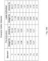
- a vacuum insulating panel capable of one or more of: (a) maintaining vacuum hermeticity, (b) maintaining in one or both glass substrates, when thermally tempered, a surface compressive stress of at least about 10,000 psi, more preferably of at least about 11,000 psi, more preferably of at least about 12,000 psi, more preferably of at least about 13,000 psi, and sometimes at least about 14,000 psi, after fabrication of the vacuum insulated glass panel, (c) maintaining in one or both glass substrates, when thermally tempered, an internal tensile stress of at least about 5,200 psi, more preferably at least about 5,500 psi, more preferably at least about 6,000 psi, more preferably at least about 6,500 psi, and most preferably at least about
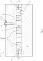
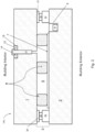
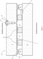
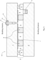
- Figs. 1-5 are side cross sectional views each illustrating a vacuum insulating panel 100 according to various example embodiments
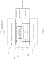
- Fig. 6 is a side cross sectional view of an example vacuum insulating unit/panel 100 showing a laser used in sintering/firing the main seal layer 30 when forming the edge seal 3 during manufacturing (which may be used in combination with any embodiment herein)
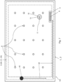
- Fig. 7 is a schematic top view of an example vacuum insulating unit/panel 100 showing a laser used in sintering/firing the main seal layer 30 when forming the edge seal 3 during manufacturing (which may be used in combination with any embodiment herein).
- Vacuum insulating panel 100 may be used in window applications (e.g., for commercial and/or residential windows), and/or for other applications such as commercial refrigeration and consumer appliance applications.
- each vacuum insulating panel 100 may include a first substrate 1 (e.g., glass substrate), a second substrate 2 (e.g., glass substrate), a hermetic edge seal 3 at least partially provided proximate the edge of the panel 100, and a plurality (e.g., an array) of spacers 4 provided between at least the substrates 1 and 2 for spacing the substrates from each other and so as to help provide low-pressure space/gap 5 between at least the substrates.
- Each glass substrate 1, 2 may be flat, or substantially flat, in certain example embodiments.
- Support spacers 4 may be of any suitable shape (e.g., round, oval, disc-shaped, square, rectangular, rodshaped, etc.) and may be of or include any suitable material such as stainless steel, aluminum, ceramic, solder glass, metal, and/or glass.
- Certain example support spacers 4 shown in the figures are substantially circular as viewed from above and substantially rectangular as viewed in cross section, and may have rounded edges.
- the hermetic edge seal 3 may include one or more of main seal layer 30, upper primer layer 31, and lower primer layer 32. Each "layer" herein may comprise one or more layers.
- the solar control coating 7 may be provided on substrate 1 or substrate 2, or such a solar control coating may be provided on both substrates 1 and 2.
- Figs. 1-3 and 6 illustrate such a coating 7 (e.g., low-E coating) provided on substrate 2
- Figs. 4-5 illustrate the coating 7 provided on substrate 1.
- Each substrate 1 and 2 is preferably of or including glass, but may instead be of other material such as plastic or quartz.
- one or both glass substrates 1 and 2 may be soda-lime-silica based glass substrates, borosilicate glass substrates, lithia aluminosilicate glass substrates, or the like, and may be clear or otherwise tinted/colored such as green, grey, bronze, or blue tinted.
- Substrates 1 and 2 in certain example embodiments, may each have a visible transmission of at least about 40%, more preferably of at least about 50%, and most preferably of from about 60-80%.
- the vacuum insulating panel 100 in certain example embodiments, may have a visible transmission of at least 40%, more preferably of at least 50%, and most preferably of at least 60%.
- the substrates 1 and 2 may be substantially parallel (parallel plus/minus ten degrees, more preferably plus/minus five degrees) to each other in certain example embodiments. Substrates 1 and 2 may or may not have the same thickness, and may or may not be of the same size and/or same material, in various example embodiments.
- each of the glass substrates may be from about 2-12 mm thick, more preferably from about 3-8 mm thick, and most preferably from about 4-6 mm thick.
- the glass may or may not be tempered (e.g., thermally tempered). Although thermally tempered glass substrates are desirable in certain environments, the glass substrate(s) may be heat strengthened.
- thermal tempering of glass typically involves heating the glass to a temperature of at least 585 degrees C, more preferably to at least 600 degrees C, more preferably to at least 620 degrees C (e.g., to a temperature of from about 6209-650 degrees C), and then rapidly cooling the heated glass so as to compress surface regions of the glass to make it stronger.
- the glass substrates may be thermally tempered to increase compressive surface stress and to impart safety glass properties including small fragmentation upon breakage.
- the substrate(s) may be tempered (e.g., thermally or chemically tempered) prior to firing/sintering of main edge seal material 30 (e.g., via laser) to form the edge seal 3.
- the substrate(s) may be heat strengthened prior to firing/sintering of the main edge seal material 30 (e.g., via laser) to form the edge seal 3.
- the substrate(s) may be tempered (e.g., thermally or chemically tempered) and heat strengthened prior to firing/sintering of the main edge seal material 30 (e.g., via laser) to form the edge seal 3.
- each vacuum insulating panel 100 optionally may also include at least one sorption getter 8 (e.g., at least one thin film getter) for helping to maintain the vacuum in low pressure space 5 by using reactive material for soaking up and/or bonding to gas molecules that remain in space 5, thus providing for sorption of gas molecules in low pressure space 5.
- the getter 8 may be provided directly on either glass substrate 1 or 2, or may be provided on a low-E coating 7 in certain example embodiments.
- the getter 8 may be laser-activated and/or activated using inductive heating techniques, and/or may be positioned in a trough/recess 9 that may be formed in the supporting substrate (e.g., substrate 2) via laser etching, laser ablating, and/or mechanical drilling.
- a vacuum insulating panel 100 may also include a pump-out tube 12 used for evacuating the space 5 to a pressure(s) less than atmospheric pressure, where the elongated pump-out tube 12 may be closed/sealed after evacuation of the space 5.
- Pump-out seal 13 may be provided around tube 12, and a cap 14 may be provided over the top of the tube 12 after it is sealed.
- Tube 12 may extend part way through the substrate 1, for example part way through a double countersink hole drilled in the substrate as shown in Figs. 1-6 . However, tube 12 may extend all the way through the substrate 1 in alternative example embodiments.
- Pump-out tube 12 may be of any suitable material, such as glass, metal, ceramic, or the like.
- the pump-out tube 12 may be located on the side of the vacuum insulating panel 100 configured to face the interior of the building when the panel is used in a commercial and/or residential window. In certain example embodiments, the pump-out tube 12 may instead be located on the side of the vacuum insulating panel 100 configured to face the exterior of the building.
- the pump-out tube 12 may be provided in an aperture defined in either substrate 1 or 2 in various example embodiments.
- Pump-out seal 13 may be of any suitable material.
- the pump-out seal 13 may be provided in the form of a substantially donut-shaped pre-form which may be positioned in a recess 15 formed in a surface of the substrate 1 or 2, so as to surround an upper portion of the tube 12, so that the pre-form can be laser treated/fired/sintered (e.g., after formation of the edge seal 3) to provide a seal around the pump-out tube 12.
- the pump-out seal 13 may be of any suitable material and/or may be dispensed in paste and/or liquid form to surround at least part of the tube 12 and may be sealed before and/or after evacuation of space 5.
- the pump-out seal material 13 may be directly applied to the glass substrate material or to a primer layer applied to the glass substrate surface prior to the pump-out seal material being applied to the substrate, in certain example embodiments.
- the tip of the tube 15 may be melted via laser to seal same, and hermetic sealing of the space 5 in the panel 100 can be provided both by the edge seal 3 and by the sealed upper portion of the pump-out tube 12 together with seal 13 and/or cap 14.
- the elongated pump-out tube 12 may be substantially perpendicular (perpendicular plus/minus ten degrees, more preferably plus/minus five degrees) to the substrates 1 and 2. Any of the elements/components shown in Figs. 1-7 may be omitted in various example embodiments.
- the evacuated gap/space 5 between the substrates 1 and 2, in the vacuum insulating panel 100, is at a pressure less than atmospheric pressure.
- the gap 5 between at least the substrates 1 and 2 may be at a pressure no greater than about 1.0 x 10 -2 Torr, more preferably no greater than about 1.0 x 10 -3 Torr, more preferably no greater than about 1.0 x 10 -4 Torr, and for example may be evacuated to a pressure no greater than about 1.0 x 10 -6 Torr.
- the gap 5 may be at least partially filled with an inert gas in various example embodiments.
- the evacuated vacuum gap/space 5 may have a thickness (in a direction perpendicular to planes of the substrates 1 and 2) of from about 100-1,000 ⁇ m, more preferably from about 200-500 ⁇ m, and most preferably from about 230-350 ⁇ m.
- Providing a vacuum in the gap/space 5 is advantageous as it reduces conduction and convection heat transport, so as to reduce temperature fluctuations inside buildings and the like, thereby reducing energy costs and needs to heat and/or cool buildings.
- panels 100 can provide high levels of thermal insulation.
- Example low-emittance (low-E) coatings 7 which may be used in the vacuum insulating panel 100 are described in U.S. Patent Nos. 5,935,702 , 6,042,934 , 6,322,881 , 7,314,668 , 7,342,716 , 7,632,571 , 7,858,193 , 7,910,229 , 8,951,617 , 9,215,760 , and 10,759,693 .
- Other low-E coatings may also, or instead, be used.
- a low-E coating 7 typically includes at least one IR reflecting layer (e.g., of or including silver, gold, or the like) sandwiched between at least first and second dielectric layer(s) of or including materials such as silicon nitride, zinc oxide, zinc stannate, and/or the like.
- at least one IR reflecting layer e.g., of or including silver, gold, or the like
- first and second dielectric layer(s) of or including materials such as silicon nitride, zinc oxide, zinc stannate, and/or the like.
- a low-E coating 7 may have one or more of: (i) a hemispherical emissivity/emittance of no greater than about 0.20, more preferably no greater than about 0.04, more preferably no greater than about 0.028, and most preferably no greater than about 0.015, and/or (ii) a sheet resistance (R s ) of no greater than about 15 ohms/square, more preferably no greater than about 2 ohms/square, and most preferably no greater than about 0.7 ohms/square, so as to provide for solar control.
- the low-E coating 7 may be provided on the interior surface of the glass substrate to be closest to the building exterior, which is considered surface two (e.g., see Figs. 2-3 ), whereas in other example embodiments the low-E coating 7 may be provided on the interior surface of the glass substrate to be closest to the building interior, which is considered surface three (e.g., see Figs. 4-5 ).
- Fig. 1 illustrates an embodiment where the edge seal 3 is provided in the vacuum insulated glass panel 100 at the absolute edge, the seal layers 30, 31 and 32 all have substantially the same width (e.g., between about 6 mm and 12 mm), and a thickness of the main seal layer 30 is less than a thickness of primer layer 31 but greater than a thickness of the other primer layer 32.
- Fig. 2 illustrates an embodiment where the edge seal 3 is spaced inwardly from the absolute edge of the panel 100, the width of the main seal layer 30 is less than a width(s) of the primer layers 31 and 32, and a thickness of the main seal layer 30 is greater than a thickness of primer layer 31 but less than a thickness of the other primer layer 32.
- Fig. 1 illustrates an embodiment where the edge seal 3 is provided in the vacuum insulated glass panel 100 at the absolute edge, the seal layers 30, 31 and 32 all have substantially the same width (e.g., between about 6 mm and 12 mm), and a thickness of the main seal layer 30 is less than a thickness of
- FIG. 3 illustrates an embodiment where the edge seal 3 is spaced inwardly from the absolute edge of the panel 100, the seal layers 30, 31 and 32 all have substantially the same width (e.g., between about 6 mm and 12 mm), and the seal layers 30, 31 and 32 all have substantially the same thickness.
- Fig. 4 illustrates an embodiment where the edge seal 3 is spaced inwardly from the absolute edge of the panel 100, the width of the main seal layer 30 is less than a width(s) of the primer layers 31 and 32, a thickness of the main seal layer 30 is greater than a thickness of primer layer 31 but less than a thickness of primer layer 32, and the low-E coating 7 is provided on substrate 1 (as opposed to the low-E coating being on substrate 2 in Figs. 1-3 ).
- Fig. 4 illustrates an embodiment where the edge seal 3 is spaced inwardly from the absolute edge of the panel 100, the width of the main seal layer 30 is less than a width(s) of the primer layers 31 and 32, a thickness of the main seal layer
- Fig. 5 illustrates an embodiment similar to Fig. 4 , except that primer layer 31 is omitted in the Fig. 5 embodiment.
- Fig. 6 provides an example where a laser beam 40 from laser 41 is being used to heat the edge seal structure for sintering/firing the main seal layer 30 to form the hermetic edge seal 3
- Fig. 7 is a top view illustrating the laser beam 40 proceeding around the entire periphery of the panel along path 42 over the edge seal layers 30-32 to fire/sinter the main edge seal layer 30 in forming the hermetic edge seal 3.
- the laser beam 40 performs localized heating of the edge seal area, so as to not unduly heat certain other areas of the panel thereby reducing chances of significant de-tempering of the glass substrates.
- Each of these embodiments may be used in combination with any other embodiment described herein, in whole or in part.
- Edge seal 3 which may include one or more of ceramic layers 30-32, may be located proximate the periphery or edge of the vacuum insulated panel 100 as shown in Figs. 1-7 .
- Edge seal 3 may be a ceramic edge seal in certain example embodiments.
- layer 30 of the edge seal may be considered a main or primary seal layer, and layers 31 and 32 may be considered primer layers.
- seal layers 30-32, of the edge seal 3 may be of or include ceramic frit in certain example embodiments, and/or may be lead-free or substantially lead-free (e.g., no more than about 15 ppm Pb, more preferably no more than about 5 ppm Pb, even more preferably no more than about 2 ppm Pb) in certain example embodiments.
- each primer layer 31 and 32 may be of a material having a coefficient of thermal expansion (CTE) that is between that of the main seal layer 30 and the closest glass substrate 1, 2.
- CTE coefficient of thermal expansion
- primer layers 31 and 32 may each have a CTE (e.g., from about 8.0 to 8.8 x 10 -6 mm/(mm*deg.
- C more preferably from about 8.3 to 8.6 x 10 -6 mm/(mm*deg. C)) which is between a CTE (e.g., from about 8.7 to 9.3 x 10 -6 mm/(mm*deg. C), more preferably from about 8.8 to 9.2 x 10 -6 mm/(mm*deg. C)) of the adjacent float glass substrate 1 and a CTE (e.g., from about 7.0 to 7.9 x 10 -6 mm/(mm*deg. C), more preferably from about 7.2 to 7.9 x 10 -6 mm/(mm*deg. C), with an example being about 7.6 x 10 -6 mm/(mm*deg. C)) of the main seal layer 30.
- a CTE e.g., from about 8.7 to 9.3 x 10 -6 mm/(mm*deg. C)
- a CTE e.g., from about 7.0 to 7.9 x 10 -6 mm/(mm
- the main seal layer 30 may have a CTE of at least 15% less than CTE(s) of the glass substrate(s) 1 and/or 2 in certain example embodiments.
- the multi-layer edge seal 3, via primer(s) 31 and/or 32 may provide for a graded CTE from the main seal 30 moving toward each glass substrate 1, 2, which provides for improved bonding of the edge seal to the glass and a more durable resulting vacuum insulating panel 100 such as capable of surviving exposure to asymmetric thermal loading and/or wind loads in the end application.
- the main seal layer 30, in certain example embodiments, need not contain significant amounts of CTE filler material (although it may contain significant amounts of filler in other example embodiments), which can result in an improved hermetic edge seal 3 and durability.
- a primer(s) 31 and/or 32 may be omitted in certain example embodiments.
- primer layers 31 and 32 may be of or include different material(s) compared to the main seal layer 30.
- one or both primer layer(s) 31 and/or 32 may have a melting point (Tm) higher than the melting point of the main seal layer 30.
- Tm melting point
- one or both primer layers 31 and/or 32 may have a melting point (Tm) of from about 500-750 degrees C (more preferably from about 575-680 degrees C, and most preferably from about 600-650 degrees C), whereas the main seal layer 30 may have a lower melting point (Tm) of from about 300 to 450 degrees C (more preferably from about 350-430 degrees C, and most preferably from about 380-420 degrees C or from about 390-410 degrees C).
- one or both of the primer layers 31 and/or 32 may have a melting point (Tm) at least 100 degrees C higher, more preferably at least 150 degrees C higher, and most preferably at least 200 degrees C higher, than the melting point of the main seal material 30.
- Tm melting point
- the main seal layer 30 may have a melting point of from about 390-410 degrees C or from about 390-395 degrees C
- the primer layers 31 and 32 may each have a melting point of from about 585-625 degrees C or from about 610-625 degrees C.
- one or both primer layer(s) 31 and/or 32 may have a transition point (Tg) higher than the transition point of the main seal layer 30.
- Tg transition point
- one or both primer layer(s) 31 and/or 32 may have a transition point of from about 400-600 degrees C (more preferably from about 425-550 degrees C, and most preferably from about 450 to 510 degrees C), whereas the main seal layer 30 may have a lower transition point of from about 200 to 350 degrees C (more preferably from about 230-330 degrees C, and most preferably from about 260 to 310 degrees C).
- one or both primer layer(s) 31 and/or 32 may have a softening point (Ts) higher than the softening point of the main seal layer 30.
- Ts softening point
- one or both primer layer(s) 31 and/or 32 may have a softening point of from about 425-650 degrees C (more preferably from about 475-620 degrees C, and most preferably from about 520 to 590 degrees C), whereas the main seal layer 30 may have a lower softening point of from about 220 to 410 degrees C (more preferably from about 270-380 degrees C, and most preferably from about 300 to 340 degrees C).
- one or both of the primer layer(s) 31 and/or 32 may have a softening point (Ts) at least 100 degrees C higher, more preferably at least about 150 degrees C higher, and most preferably at least about 150 or 200 degrees C higher, than the softening point (Ts) of the main seal layer material 30.
- Ts softening point
- the main seal layer 30 may have a softening point of from about 310-330 degrees C
- the primer layers 31 and 32 may each have a softening point of from about 540-560 degrees C.
- the main seal layer 30 may have a melting point of from about 390-395 degrees C, whereas the primer layers 31 and 32 may each have a melting point of from about 610-625 degrees C.
- These feature(s) advantageously may allow each high melting point primer layers 31 and 32 to provide strong mechanical bonding with the supporting glass substrate (1 and/or 2) via sintering/firing in a first bulk heating step in an oven or other heater (e.g., heating above the melting point and/or softening point of the primer(s) while thermally tempering the glass substrate 1, 2 on which the primer is provided), and thereafter sintering/firing the lower melting point main seal material 30 in a different second heating step (e.g., via laser) to bond the main seal layer 30 to the previously sintered/fired primers 31 and 32 and form the edge seal 3 without significantly de-tempering the glass substrates.
- the main seal layer 30 and primers 31 and 32 can be sintered/fired in different heating steps, in a manner which allows thermal tempering of the glass substrates 1 and 2 when sintering/heating the primers on the respective glass substrates, and which allows the main seal layer 30 to thereafter be sintered and bonded to the primers 31 and 32 without significantly de-tempering the glass substrates 1 and 2.
- the edge seal 3, in certain example embodiments, may be located at an edgedeleted area (where the solar control coating 7 has been removed) of the substrate as shown in Figs. 1-6 , so as to reduce chances of corrosion. Thus, the edge seal 3 may be positioned so that it does not overlap the low-E coating 7 in certain example embodiments.
- the edge seal 3 may be located at the absolute edge of the panel 100 (e.g., Fig. 1 ), or may be spaced inwardly from the absolute edge of the panel 100 as shown in Figs. 2-7 and 9 , in different example embodiments.
- An outer edge of the hermetic edge seal 3 may be located within about 50 mm, more preferably within about 25 mm, and more preferably within about 15 mm, of an outer edge of at least one of the substrates 1 and/or 2.
- an "edge" seal does not necessarily mean that the edge seal 3 is located at the absolute edge or absolute periphery of a substrate(s) or overall panel 100.
- the low-E coating 7 may be edge deleted around the periphery of the entire unit so as to remove the low-e coating material from the coated glass substrate.
- the low-E coating 7 edge deletion width (edge of glass to edge of low-E coating 7), in certain example embodiments, in at least one area may be from about 0-100 mm, with examples being no greater than about 6 mm, no greater than about 10 mm, no greater than about 13 mm, no greater than about 25 mm, with an example being about 16 mm.
- adjusting the width (as viewed from above and/or in cross-section) of the main seal layer 30, of the edge seal can be technically advantageous. It has been found that when the main seal layer 30 is too wide, this results in undesirably high induced transient thermal stress in the main seal layer 30 which can lead to seal failures (e.g., one or more of moisture vapor transmission, mechanical failure, adhesive failure, and/or cohesive failure) and a non-durable product.
- Fig. 18 is a graph plotting main seal layer 30 width (mm) vs. induced transient thermal stress (MPa) in the main seal layer 30 and glass substrate 1 and/or 2, after firing/sintering of the main seal layer 30. It can be seen in Fig.
- Fig. 18 illustrates that a main seal layer 30 having a width "W” (e.g., see “W” in Fig. 9 ) of 6 mm realized an induced transient thermal stress of about 16-17 MPa, whereas a main seal layer 30 having a width "W” of 10 mm realized a higher induced transient thermal stress of about 28 MPa (the lower the induced transient thermal stress, the better).
- W width
- a main seal layer 30 having a width "W” of 10 mm realized a higher induced transient thermal stress of about 28 MPa (the lower the induced transient thermal stress, the better).
- Reduced width of the main seal layer 30 can also improve U-value/U-factor performance of panel 100.
- Figs. 2 , 4 , 7 and 9 illustrate that the main edge seal layer 30 has a width less than the width of one or both of the adjacent primer layers 31 and 32. For example, see the width "W" of the main seal layer 30 in Fig. 9 .
- the width of the main seal layer 30 may be about 6 mm.
- primer layer 31 may have a width similar to the width Wp of primer layer 32 in certain example embodiments. It has surprisingly been found that when the primer layers 31 and 32 are too narrow (e.g., Wp is too small), defects such as fish scales, glass micro-cracking, or the like, tend to occur in the final product which can lead to seal failures and/or a non-durable product.
- the primer layers 31 and/or 32 may act as heat sinks during laser sintering/firing of the main seal layer 30, thereby allowing heat to be dissipated from the glass and the main seal layer, and thus induced stress and/or de-tempering to be reduced.
- wider primer layers allow more heat to be dissipated during the laser sintering/firing process of the main seal layer 30, thereby resulting in less glass substrate and seal layer defects, and less de-tempering of the glass substrate(s).
- Wider primer layers 31 and/or 32 also may advantageously block or reduce some ultraviolet (UV) radiation from reaching the main seal layer 30 and interacting with residual carbon in the main seal layer 30. Moreover, if the primer layer(s) 31 and/or 32 is/are made too narrow, this can reduce the bonding area resulting in edge seal failures for that reason such as during a lap shear strength test.
- Figs. 2 , 4 , 7 and 9 illustrate that the main edge seal layer 30 has a width "W" less than the width (e.g., "Wp") of the adjacent primer layers 31 and 32.
- the width of the main seal layer 30 may be about 6 mm and the width of the primer layers 31 and 32 may be about 10 mm, so that the width of one or both of the primer layers is greater than the width of the main seal layer (e.g., see Figs. 2 , 4 , 5 , 7 and 9 ).
- the width of the ceramic sealing glass primer layer 31 may be about 8 mm
- the width of the ceramic sealing glass primer layer 32 may be about 8 mm
- the width of the ceramic main seal layer 30 may be about 6 mm or about 3-4 mm.
- the main seal layer 30 of the edge seal 3 may have an average width W of from about 2-20 mm, more preferably from about 4-10 mm, more preferably from about 3-9 mm or from about 4-8 mm, still more preferably from about 5-7 mm, and with an example main seal layer 30 average width being about 6 mm; and/or one or both of the primer layers 31 and 32 may have an average width Wp of from about 2-20 mm, more preferably from about 6-14 mm, more preferably from about 8-12 mm, still more preferably from about 9-11 mm, and with an example primer average width being about 10 mm.
- the respective width(s) of each layer 30, 31, and 32 may be substantially the same (the same plus/minus 10%, more preferably plus/minus 5%) along the length of the edge seal 3 around the periphery of the entire panel 100.
- one or both primer layers 31 and/or 32 is/are at least about 1 mm wider, more preferably at least about 2 mm wider, and most preferably at least about 3 mm wider, than the main seal layer 30 at one or more locations around the periphery of the panel 100 and possibly around the entire periphery of the panel.
- These desirable widths for ceramic seal layers 30-32 in the panel 100 may be appropriate when using the materials for seal layers 30-32 discussed herein (e.g., see Figs. 11-14 ), and may be adjusted in an appropriate manner if different seal materials are instead used which is possible in certain example embodiments.
- Other widths for one or more of seal layers 30-32, not discussed herein, may be used in various other example embodiments.
- the lateral edge(s) 30a and/or 30b of the main seal layer 30 may be spaced inwardly an offset distance "D" from the respective lateral edges of the primer seal layer 31 and/or the primer seal layer 32 on each side of the main seal layer.
- the offset distance "D" on one or both sides of the main seal layer 30 may be from about 0.5 to 6.0 mm, more preferably from about 0.5 to 3.0 mm, more preferably from about 0.5 to 2.5 mm, more preferably from about 1.0 to 2.5 mm, and most preferably from about 1.5 to 2.5 mm, with an example being about 2.0 mm on each side, although the offset distance "D" may be different on the left and right sides of the main seal layer as viewed in Fig. 9 for example.
- the offset distance "D" on one or both sides of the main seal layer 30 may be at least about 0.5 mm, more preferably at least about 1.0 mm, and most preferably at least about 1.5 mm, as shown in Fig. 9 for example. See also Figs. 2 , 4 and 6 .
- the multi-layer edge/perimeter seal 3 stack may be designed regarding one or more of moisture vapor transmission rate, hydrogen transmission rate, oxygen transmission rate, mechanical strength, thermal expansion, thermal diffusivity (TD), and/or thermal conductivity (TC).
- the main seal layer 30 may be narrower in width than at least one primer to reduce thermal conductance between the opposing substrates.
- thermal conductivity of soda lime silicate float glass e.g., which may be used for one or more of the substrates 1, 2) may be about 1.11 W/mK.
- layer 30 may have a lower thermal conductivity than traditional amorphous glass materials, e.g., 0.88 W/mK versus 1.10 W/mK.
- one or both of the ceramic sealing primer layers 31-32 of the edge seal 3 may have a thermal conductivity(ies) of from about 1.00 to 1.90, or from about 1.40 W/mK to 1.80 W/mK, with an example being about 1.60 W/mK, which may be higher than the thermal conductivity of the glass substrates 1 and 2.
- Certain example embodiments may provide a ratio: TCml ⁇ TCg ⁇ TCpl, where TCml is the thermal conductivity of the main seal layer 30, TCg is the thermal conductivity of one or more of the glass substrates 1 and/or 2, and TCpl is the thermal conductivity of one or both primer layers 31 and/or 32.
- This ratio arrangement may advantageously improve the end of glass U-factor when reducing width(s) of a seal layer(s) (e.g., compared to a traditional 12 mm width), so as to optimize the volumetric amount(s) of one or more of the edge seal layer(s) for improving the overall U-factor of the glazing.
- the thickness of the edge seal 3 it has surprisingly and unexpectedly been found that adjusting the physical thickness of the main seal layer 30 can be technically advantageous. It has been found that when the main seal layer 30 is too thick, this can result in significant de-tempering of the glass substrate(s) 1 and/or 2 (e.g., due to increased thermal heating and/or lasing time), hermiticity problems with the edge seal 3, and/or cohesive strength problems (e.g., due to reduction in density with firing/sintering of the main seal layer 30), which can lead to seal failures and a non-durable product.
- the main seal layer 30 is too thick, there would be too much material for a laser to create sufficient heat to fuse/sinter and provide adequate bonding to the glass substrate(s) and/or primer layer(s). And if one were to heat such a thick layer long enough via laser to generate sufficient heat for sintering, this may significantly degrade seal density which may result in one or more of seal failures (e.g., from one or more of water exposure, moisture vapor transmission, hydrogen and/or oxygen permeation, asymmetric thermal shock and/or wind load) and a non-durable product, cause excessive heat which may lead to significant glass de-tempering, cause excess heat to crack the glass (e.g., fish scales), and/or take too long to be commercially viable from a commercial cost point of view.
- seal failures e.g., from one or more of water exposure, moisture vapor transmission, hydrogen and/or oxygen permeation, asymmetric thermal shock and/or wind load
- a non-durable product cause excessive heat which may lead to significant glass de
- Figs. 1-2 , 4 , 6 , and 9 illustrate that the main seal layer 30 may have a thickness which is: (a) less than a thickness of adjacent primer layer 32, and (b) greater than a thickness of the other adjacent primer layer 31.
- a thickness of the main seal layer 30 may have a thickness which is: (a) less than a thickness of adjacent primer layer 32, and (b) greater than a thickness of the other adjacent primer layer 31.
- the total thickness of the overall edge seal is about 270 ⁇ m.
- a vacuum insulating panel was built with a 270 ⁇ m edge seal 3 made of only a main seal layer 30 (no primers were used), so that the layer 30 directly contacted both glass substrates.
- the main seal layer 30 was made of the ceramic tellurium (Te) oxide-based seal material shown in Figs. 11-12 and 14 .
- Te ceramic tellurium
- This edge seal failed. This edge seal suffered from separation from the glass substrates at multiple locations around the unit, indicating failure and loss of vacuum.
- the defects included fish scaling from the laser, adhesive delamination associated with the main seal layer 30.
- this same ceramic tellurium (Te) oxide-based seal material shown in Figs. 11-12 and 14 provides for excellent results when its thickness is reduced and it is used as a main seal layer 30 together with at least one primer(s) 31 and/or 32 of different material(s).
- a main seal layer 30 e.g., of the main seal material shown in Figs.
- 11-12 , 14 having a thickness of from about 30-120 ⁇ m, more preferably from about 40-100 ⁇ m, and most preferably from about 50-85 ⁇ m, provides for excellent results and a durable vacuum insulating panel 100 (e.g., see Figs. 1-6 and 9 ).
- the primers 31-32 may be made of opaque or semi-opaque material, so that some of the laser beam 40 is blocked from reaching layer 30 during firing/sintering, with the amount blocked being based on the thickness of the primer 31 in the Fig. 6 embodiment for instance.
- the beam 40 need not pass through primer layer 32, and it would be desirable to make primer layer 32 thicker because it does not have a bearing on the laser beam 40, and so that it can provide good adhesion and act as a better heat sink during sintering/firing of layer 30.
- the main seal layer 30 of the edge seal 3 may have an average thickness of from about 30-120 ⁇ m, more preferably from about 40-100 ⁇ m, and most preferably from about 50-85 ⁇ m, with an example main seal layer 30 average thickness being from about 60-80 ⁇ m as shown in Fig. 9 .
- the primer layer 31 of the edge seal 3 may have an average thickness of from about 10-80 ⁇ m, more preferably from about 20-70 ⁇ m, and most preferably from about 20-55 ⁇ m, with an example primer layer 31 average thickness being about 45 ⁇ m as shown in Fig.
- the primer layer 32 (opposite the side from which the laser beam 40 is directed) of the edge seal 3 may have an average thickness of from about 100-220 ⁇ m, more preferably from about 120-200 ⁇ m, and most preferably from about 120-170 ⁇ m, with an example primer layer 32 average thickness being about 145 ⁇ m as shown in Fig. 9 .
- the thickness of the main seal layer 30 may be at least about 30 ⁇ m thinner (more preferably at least about 45 ⁇ m thinner) than the thickness of the primer seal layer 32, and may be at least about 10 ⁇ m thicker (more preferably at least about 20 ⁇ m, and more preferably at least about 30 ⁇ m thicker) than the thickness of the primer seal layer 31.
- the overall average thickness of the edge seal 3 may be from about 150-330 ⁇ m, more preferably from about 200-310 ⁇ m, and most preferably from about 240-290 ⁇ m, with an example overall edge seal 3 average thickness being about 270 ⁇ m as shown in Fig. 9 .
- the respective thicknesses of each layer 30, 31, and 32 are substantially the same (the same plus/minus 10%, more preferably plus/minus 5%) along the length of the edge seal 3 around the periphery of the entire panel 100.
- a vacuum insulating panel 100 having an improved multi-layer perimeter seal structure 3 provides for improved manufacturing of tempered units using localized laser firing and/or methods of making the same.
- a first ceramic sealing glass material 31 may acts as primer layer, t 1
- a second ceramic sealing glass material 32 may act as a second primer layer, t 2
- a third ceramic sealing glass material 30 with a thickness, t 3 may be applied onto the first sealing glass material and seals together the vacuum insulating unit using localized laser sintering and melting of the third ceramic sealing glass material.
- ceramic sealing glass material for primer layer 31 is semi-transparent to laser energy (e.g., 808 or 810 nm energy) due to the limited thickness of the thin primer layer, and may have a physical thickness from about 10 ⁇ m to about 80 ⁇ m with a preferred thickness of about 40 ⁇ m.
- the overall perimeter seal 3 thickness can range between about 100-400 ⁇ m, more preferably from 150-330 ⁇ m, with an example total thickness of about 270 or 280 ⁇ m.
- the thickness of the ceramic sealing glass primer layer 32 may can range from about 100-250 or 100-220 ⁇ m, with an example thickness of about 145 or 200 ⁇ m.
- the thickness of the other ceramic sealing glass primer layer 31 may range between about 10-100 or 10-80 ⁇ m, with an example thickness of about 40 or 45 ⁇ m.
- the thickness of the main seal layer 30 may range from about 10-100 ⁇ m or 30-120 ⁇ m, with an example thickness of about 40 or 45 ⁇ m.
- the primer layer 31 and/or main seal layer 30 may be designed and optimized to have a high thermal diffusivity to transfer heat from the laser source through the primer layer 31 and main seal layer 30 to fully sinter the main sealing layer 30 and wet the interfaces between the main layer 30 and opposing primer layers 31-32.
- These thicknesses for ceramic seal layers 30-32 in the panel 100 may be appropriate when using the materials for seal layers 30-32 discussed herein (e.g., see Figs. 11-14 ), and may be adjusted in an appropriate manner such as if different seal materials are instead used which is possible in certain example embodiments.
- Other thicknesses for layers 30-32, not discussed herein, may be used in various other example embodiments.
- laser 41 may be selected to emit a laser beam 40 having a wavelength ( ⁇ ) of from about 380 to 1064 nm, more preferably from about 550 nm to 1064 nm, more preferably from about 780-1064 nm.
- Laser 41 may be a near IR laser in certain example embodiments.
- Laser 41 may be a continuous wave laser, a pulsed laser, and/or other suitable laser in various example embodiments.
- the laser 41 may be a scanning laser system comprising diode laser, solid state laser (e.g., ND:YAG), gas laser (e.g., CO 2 of 9.3-10.6 ⁇ m), and/or other laser devices/sources.
- laser 41 may emit a laser beam 40 at or having a wavelength of about 800 nm, 808 nm, 810 nm, 940 nm, or 1090 nm (e.g., YVO4 laser).
- YVO4 laser e.g., 808 nm or 810 nm diode lasers; or 914 nm, 940, 1064 nm, or 1342 nm solid state lasers (e.g., YVO4 lasers).
- more than one laser may be utilized to increase the sealing speed, lower effective laser power levels and/or reduce laser spot size.
- Two lasers operating in a serial, overlapping manner can increase the effective irradiation spot time to achieve for example 0.5 seconds while achieving for example a 20 mm per second linear laser rate, as an example.
- Two 9-mm laser diameter beams 40 can operate in a serial fashion for a 0.5 second to 1.0 second irradiation time.
- Figs. 11-12 and 14 illustrate an example material(s) that may be used for the main seal layer 30 in various example embodiments, including for example in any of the embodiments of Figs. 1-9 .
- suitable materials vanadium oxide based ceramic materials with little or no Te oxide, solder glass, or the like
- Fig. 11 is a table/graph showing weight % and mol % of various compounds/elements in an example main seal 30 material, prior to sintering of layer 30, according to an example embodiment (measured via non-carbon detecting XRF); Fig.
- FIG. 12 is a table/graph showing weight % and mol % of various compounds/elements in an example main seal 30 material according to an example embodiment (measured via carbon detecting XRF), before and after laser treatment/sintering of the main seal layer 30 for edge seal formation; and the left side of Fig. 14 sets forth a table/graph showing an elemental analysis (non-oxide analysis) of weight % and mol % of various elements in an example main seal 30 material, before and after laser treatment for edge seal formation.
- Fig. 14 sets forth a table/graph showing an elemental analysis (non-oxide analysis) of weight % and mol % of various elements in an example main seal 30 material, before and after laser treatment for edge seal formation.
- X-ray Fluorescence is a non-destructive technique that can identify and quantify the elemental constituents of a sample using the secondary fluorescence signal produced by irradiation with high energy x-rays
- WDXRF wavelength dispersive spectrometer
- This ceramic tellurium (Te) oxide based main seal material shown in Figs. 11-12 and 14 , was used for main seal layer 30 in examples tested for obtaining data herein for various figures/tables unless otherwise specified.
- This ceramic tellurium (Te) oxide based main seal material shown in Figs. 11-12 and 14 , for example may be considered to have a melting point (Tm) of 390 or 395 degrees C, a softening point (Ts) of 320 degrees C, and a glass transition point (Tg) of 290 degrees C.
- Table 1A sets forth example ranges for various elements and/or compounds for this example tellurium (Te) oxide based main seal 30 material according to various example embodiments, for both mol % and weight %, prior to firing/sintering thereof and thus prior to hermetic edge seal 3 formation.
- the main seal layer 30 may comprise mol% and/or wt.% of the following compounds in one or more of the following orders of magnitude: tellurium oxide > vanadium oxide > aluminum oxide, tellurium oxide > vanadium oxide > silicon oxide, tellurium oxide > vanadium oxide > aluminum oxide > magnesium oxide, and/or tellurium oxide > vanadium oxide > silicon oxide > magnesium oxide, before and/or after firing/sintering of the layer 30.
- Tellurium oxide e.g., TeO 4 and/or other stoichiometry 20-60% or 40-90% 25-50% or 40-70% 30-42% 20-70% 30-65% 40-55% Vanadium oxide (e.g., VO 2 and/or other stoichiometry) 5-45% or 5-58% 10-30% or 5-37% 15-21% 5-50% 8-38% 18-28%
- Aluminum oxide e.g., Al 2 O 3 and/or other stoichiometry
- Silicon oxide e.g., SiO 2 and/or other stoichiometry 0-50% or 0-5% 10-30% 15-25% 0-50% 3-30% 5-20%
- Magnesium oxide e.g., MgO and/or other stoichiometry
- 0-10% 3-30% 5-15% 0-50% 1-12% 2-7% Barium oxide e.g.
- Tellurium Vanadate based and/or inclusive glasses are ideally suited for the main seal functionality when utilizing laser irradiation for the firing/sintering of the main seal layer 30.
- the base main seal material may comprise tellurium oxide (e.g., a combination of TeO 3 , TeO 3+1 , and TeO 4 ) and vanadium oxide (e.g., a combination of V 2 O 5 , VO 2 , and V 2 O 3 ) per the weight % and/or mol % described in Table 1A.
- the Te oxide e.g., one or more of TeO 4 , TeO 3 , TeO 3+1 , and/or other stoichiometry(ies) involving Te and O
- V oxide e.g., one or more of VO 2 , V 2 O 5 , V 2 O 3 , and/or other stoichiometry(ies) involving V and O
- Table 1B tellurium oxide stoichiometries prior to firing/sintering
- Table 1C tellurium oxide stoichiometries after firing/sintering
- Table 1D vanadium oxide sto
- the "Example” column in Table 1B indicates that 57% of the Te present in the material prior to sintering/firing was in an oxidation state of TeO 4 , 42% of the Te present in the material prior to sintering/firing was in an oxidation state of TeO 3 , and 1% of the Te present in the material prior to sintering/firing was in an oxidation state of TeO 3+1 .
- Example column in Table 1C indicates that after the laser firing/sintering of the main seal layer 30 just 14% of the Te present in the main seal layer 30 material was in an oxidation state of TeO 4 , but 81% of the Te present in the material was in an oxidation state of TeO 3 , and 5% of the Te present in the material prior to sintering/firing was in an oxidation state of TeO 3+1 .
- the laser firing/sintering of the main seal layer 30 may cause much of the TeO 4 to transform/convert into TeO 3 and TeO 3+1 , which is advantageous because it increases the material's absorption in the near infrared (e.g., 808 or 810 nm for example, which may be used for the laser during sintering/firing) which provides for increased heating efficiency and reducing the chances of significantly de-tempering the glass substrate(s) due to improved heating efficiency during the firing/sintering.
- the near infrared e.g., 808 or 810 nm for example, which may be used for the laser during sintering/firing
- Fig. 30 is a Binding Energy (eV) vs. Intensity graph illustrating the shift in binding energy for Te in the main seal layer 30 caused by laser sintering/firing thereof according to an example embodiment. It can be seen that the laser sintering/firing led to a distinct shift in binding energy associated with Te in main seal layer 30. A binding energy shift toward depolymerized tellurite structures. The laser sintering/firing of the main seal layer 30 also caused the binding energy peak for V to shift in a distinct manner, corresponding to a reduction of V 5+ to V 4+ /V 3+ in the main seal layer 30.
- eV Binding Energy
- the laser sintering/firing of the main seal layer 30 may cause at least one of in the main seal layer 30: (a) a binding energy shift of the Te peak of at least about 0.15 eV, more preferably of at least about 0.20 eV, and most preferably of at least about 0.25 or 0.30 eV, which resulted in the stoichiometry changes discussed in Tables 1B-1C and the related advantages discussed above, and/or (b) a binding energy shift of the V peak of at least about 0.10 eV, more preferably of at least about 0.15 eV, which resulted in the stoichiometry changes discussed in Tables 1D-1E and the related advantages discussed above.
- the laser sintering/firing of the preform seal 13 for the pump-out tube seal did not result in a distinct binding energy shift of the Te peak or the V peak for preform 13, demonstrating that not all laser sintering/firing techniques have such an effect.
- the material for the main seal layer 30 may include tellurium oxide with the following stoichiometry/oxidation state ratio(s) in terms of what oxidation state(s) are used by the Te in the material (e.g., see Table 1B): TeO 4 > TeO 3 > TeO 3+1 .
- TeO 4 > TeO 3 > TeO 3+1 the laser sintering/firing of the main seal layer may then cause the Te stoichiometry ratios/states to change to the following during/after sintering/firing: TeO 3 > TeO 4 > TeO 3+1 , which is advantageous in vacuum insulating panels as discussed above.
- the TeO 4 is a trigonal bipyramid structure
- TeO 3 is a trigonal pyramid structure
- TeO 3+1 is a polyhedral structure.
- Tellurium oxide may have, for example, a Tg of about 305 degrees C, a crystallization temperature (Tx) of about 348 degrees C, and a Tm about 733 degrees C.
- the "Example” column in Table 1D indicates that 84% of the V present in the material prior to sintering/firing was in an oxidation state of V 2 O 5 , 15% of the V present in the material prior to sintering/firing was in an oxidation state of VO 2 , and 1% of the V present in the material prior to sintering/firing was in an oxidation state of V 2 O 3 .
- Example column in Table 1E indicates that after the laser firing/sintering of the main seal layer just 25% of the V present in the main seal layer 30 material was in an oxidation state of V 2 O 5 , but 63% of the V present in the material was in an oxidation state of VO 2 , and 12% of the V present in the material prior to sintering/firing was in an oxidation state of V 2 O 3 .
- the other columns in Tables 1B-1E represent the same, with different values as shown.
- the laser firing/sintering of the main seal layer 30 may cause much of the V 2 O 5 to transform/convert into VO 2 and V 2 O 3 , which is advantageous because it increases the material's density and thus the hermiticity and durability of the seal (e.g., VO 2 results in a more dense layer than does V 2 O 5 ).
- the glass network becomes more closed with decreasing V 2 O 5 concentration, e.g., due to the reduction of non-bridging oxygen resulting in a higher density seal which improves water/moisture resistance, mechanical strength (adhesive and cohesive), and/or hermeticity.
- the Tg of the main seal 30 material may also slightly increase with a reduction in V 2 O 5 .
- the vanadium oxide in the main seal layer material, before firing/sintering of the main seal layer 30, may include the following stoichiometry/oxidation state ratio(s): V 2 O 5 > VO 2 > V 2 O 3 . But the laser sintering/firing of the main seal layer 30 may then cause the V stoichiometry ratios/states to change to the following during/after sintering/firing: VO 2 > V 2 O 5 > V 2 O 3 , which is advantageous in vacuum insulating panels as discussed at least because it allows for higher density in the final seal layer.
- V 2 O 5 is an orthorhombic structure
- VO 2 is a tetragonal structure
- V 2 O 3 is corundum structured in the monoclinic C2/c space group.
- Vanadium is an insulator in a base form due to empty d-bands and acts as a network former/network modifier in the presence of tellurium oxide in the main seal material for layer 30 and/or the pump-out tube seal in certain example embodiments.
- Vanadium oxide may have, for example, a Tg about 250 degrees C, a crystallization temperature (Tx) about 300 degrees C, and a Tm about 690 degrees C.
- an optimized type of laser processing e.g., 808 or 810 nm continuous wave laser using the process in Fig. 22 and a laser beam size of about 6 mm, following a pre-heat to about 300-320 degrees C
- an optimized type of laser processing may be used to sinter/fire the main seal layer 30 in a manner that causes one or more, or any combination, of the following to occur during and/or as a result of the sintering/firing: (a) stoichiometry values/oxidation states of Te in the layer to change from TeO 4 > TeO 3 > TeO 3+1 prior to laser firing/sintering, to TeO 3 > TeO 4 > TeO 3+1 following laser firing/sintering of the layer 30; (b) stoichiometry values/oxidation states of Te in the layer to change from TeO 4 > TeO 3 prior to laser firing/sintering, to TeO 3 >
- This main seal material(s) from Table 1 and Figs. 11-12 , 14 may also be used for the pump-out tube seal 13, with or without a primer, in certain example embodiments, although other types of seals may also be used such as vanadium oxide based ceramic sealing glass or solder glass.
- Other compounds may also be provided in this main seal 30 material, including but not limited to, on a weight and/or mol basis, for example one or more of: 0-15% (more preferably 1-10%) tungsten oxide; 0-15% (more preferably 1-10%) molybdenum oxide; 0-60% (or 38-52%) zinc oxide; 0-15% (more preferably 0-10%) copper oxide, and/or other elements shown in the figures.
- Table 2 sets forth example ranges for various elements and/or compounds for this example tellurium oxide-based material for main seal layer 30 according to various example embodiments, for both mol % and weight %, after firing/sintering thereof and thus after hermetic edge seal 3 formation. It will be appreciated that other materials may be used together, or in place of, those shown below, and that the example percentages may be different in alternate embodiments.
- TABLE 2 (example material for main seal layer 30 after laser firing/sintering) General More Preferred Most Preferred General More Preferred Most Preferred (Mol %) (Mol %) (Wt. %) (Wt. %) (Wt. %) (Wt. %) (Wt. %) (Wt. %) (Wt. %) (Wt. %) (Wt.
- Tellurium oxide e.g., TeO 3 and/or other stoichiometry 20-60% or 40-90% 38-70% 50-60% 20-80% 40-70% 50-65% Vanadium oxide (e.g., VO 2 and/or other stoichiometry) 5-45% or 5-58% 8-30% or 5-37% 20-25% 10-50% 12-40% 25-30%
- Aluminum oxide e.g., Al 2 O 3 and/or other stoichiometry
- Silicon oxide e.g., SiO 2 and/or other stoichiometry 0-50% or 0-5% 3-30% 5-20% 0-50% 1-25% 1-10%
- Magnesium oxide e.g., MgO and/or other stoichiometry
- This material from Tables 1-2 and Figs. 11-12 , 14 may also be used for the pump-out tube seal 13, with or without a primer, in certain example embodiments, although other types of seals may also be used such as vanadium oxide based ceramic sealing glass or solder glass.
- Other compounds may also be provided in or for this main seal 30 material, including but not limited to, on a weight or mol basis, for example one or more of: 0-15% (more preferably 1-10%) tungsten oxide; 0-15% (more preferably 1-10%) molybdenum oxide; 0-60% (or 38-52%) zinc oxide; 0-15% (more preferably 0-10%) copper oxide, and/or other elements shown in the figures. Certain elements may change during firing/sintering, and certain elements may at least partially burn off during processing prior to formation of the final edges seal 3.
- the wt.% of aluminum oxide (e.g., Al 2 O 3 and/or other stoichiometry) in the main seal layer 30 material was 13.93% prior to laser sintering of the layer 30, but was 7.18% after laser sintering of the main seal layer 30. The same may apply if this material is used for the pump-out tube seal.
- aluminum oxide e.g., Al 2 O 3 and/or other stoichiometry
- the wt% of aluminum oxide dropped 48% due to laser sintering of the main seal layer 30, presumably due to the spike in laser heating of the material for a short period of time during such laser treatment which appears to have created different oxidation rates than what one would see in a thermal oven with a much slower thermal ramp, lower temperatures and longer duration.
- the wt.% of aluminum (Al) in the main seal layer 30 material was 8.43% prior to laser sintering of the layer 30, but was 4.89% after laser sintering of the main seal layer 30.
- the wt% of Al dropped 42% on an elemental basis due to the laser sintering of the main seal layer 30, again presumably due to the spike in laser heating of the material for a short period of time during such laser treatment.
- the wt.% of aluminum (Al) in the pump-out tube seal layer 13 was 7.29% prior to laser sintering of the pump-out tube seal layer, but dropped to 4.63% after laser sintering of the pump-out tube seal layer 13.
- optimized laser sintering may cause the wt% of aluminum oxide in main seal layer 30 and/or pump-out seal 13 (e.g., Al 2 O 3 or other suitable stoichiometry) to decrease by at least about 20%, more preferably by at least about 30%, and most preferably by at least about 40%.
- main seal layer 30 and/or pump-out seal 13 e.g., Al 2 O 3 or other suitable stoichiometry
- optimized laser sintering may cause the wt% of elemental Al to decrease by at least about 20%, more preferably by at least about 30%, and most preferably by at least about 35%, in the main seal layer 30 and/or the pump-out tube seal layer 13.
- the final main seal material 30 and/or pump-out seal material may comprise from about 4-8% aluminum (on an elemental wt% basis), more preferably from about 4-6% or from about 3-5%. This is technically advantageous in that it results in a seal layer 30 and/or a pump-out tube seal layer 13 that is more dense, which reduces porosity and improves hermiticity and strength of the seal.
- the laser processing of the seal material is designed to densify aluminum (and/or its compound(s)), thereby resulting for example in such a reduction in Al due to laser sintering in order to provide for improved seal density.
- processing including optimized laser sintering may cause the wt% of elemental Mg to decrease by at least about 20%, more preferably by at least about 50%, and most preferably by at least about 75%, in the main seal layer 30 and/or the pump-out tube seal layer 13.
- processing including optimized laser sintering may cause the wt% of Mg oxide (MgO or other stoichiometry) to decrease by at least about 20%, more preferably by at least about 50%, and most preferably by at least about 75%, in the main seal layer 30 and/or the pump-out tube seal layer 13.
- the final main seal material 30 and/or pump-out seal 13 material may comprise from about 0.1-3% Mg (on an elemental wt% basis), more preferably from about 0.1-1.5%; and/or from about 0.1-3% Mg oxide (on a wt% basis), more preferably from about 0.1-1.5%, and most preferably from about 0.2 to 0.6%.
- particle size for the material of the main seal layer 30 may be optimized for reduced particle size (e.g., for the D50 distribution) to improve material density and moisture resistance, and/or to improve thermal diffusivity.
- Traditional ceramic sealing glass materials have a D50 in the range of about 60.0 um to about 90.0 um which is acceptable for a thermal oven sintering process as an example, but has been found to experience some issues for laser processing. For laser processing, it has been found that improved results can be achieved by reducing particle size of the main seal layer 30.
- the average D50 particle size and PSD mean may be significantly lower than traditional ceramic sealing glasses, as particle size is related to a thermal diffusivity rate of the ceramic sealing glass materials.
- the main seal layer 30 may have an average particle/grain size (D50) of from about 5-25 ⁇ m, more preferably from about 5-20 ⁇ m, more preferably from about 5-15 ⁇ m, and most preferably from about 10-15 ⁇ m. These same particle sizes may also be used for one or both primer layers 31 and/or 32, and/or tube seal material 13, before and/or after firing/sintering.
- D50 average particle/grain size
- the material for the main seal layer 30 may include filler.
- the filler may, for example, comprise one or more of zirconyl phosphates, dizirconium diorthophosphates, zirconium tungstates, zirconium vanadates, aluminum phosphate, cordierite, eucryptite, ekanite, alkaline earth zirconium phosphates such as (Mg,Ca,Ba,Sr) Zr 4 P 5 0 24 , either alone or in combination. Filler in a range of 20-25 wt. % may be used in layer 30 in certain example embodiments.
- Main seal layer 30, and/or the primer layer(s) 31 and/or 32 is/are lead-free and/or substantially lead-free in certain example embodiments.
- Table 3 sets forth example ranges for various elements for this example tellurium oxide based main seal 30 material according to various example embodiments, using elemental analysis (non-oxide analysis) for both mol % and weight %, prior to firing/sintering thereof and thus prior to hermetic edge seal 3 formation.
- Fig. 14 also provides an elemental analysis for various example seal materials, including for Te oxide based main seal and/or pump-out tube seal layers 30 and 13.
- the main seal layer 30 and/or the pump-out seal layer 13 may comprise mol% and/or wt.% of the following elements in one or more of the following orders of magnitude: Te > V > Al, Te > V > Si, Te > V > Al > Mg, Te > O > V, Te > O > V > Al, and/or Te > V > Si > Mg, before and/or after firing/sintering of the layer (e.g., see also Fig. 14 ). It will be appreciated that other materials may be used together, or in place of, those shown below, and that the example percentages may be different in alternate embodiments.
- the elemental Te/V ratio in the main seal layer 30 and/or seal layer 13, after sintering/firing and in terms of weight %, may be from about 1.5:1 to 5:1, more preferably from about 2:1 to 4:1, and most preferably from about 2.5:1 to 3.5:1.
- the elemental Te/Al ratio in the main seal layer 30 and/or seal layer 13, after firing/sintering thereof and in terms of weight % may be from about 5:1 to 35:1, more preferably from about 8:1 to 20:1, and most preferably from about 9:1 to 15:1.
- the elemental Si/Mg ratio in the main seal layer 30 and/or seal layer 13, after firing/sintering thereof and in terms of weight %, may be from about 1:1 to 35:1, more preferably from about 2:1 to 10:1, and most preferably from about 3:1 to 7:1. It has been found that one or more of these ratios is technically advantageous for achieving desirable melting points, softening points, and/or thermal diffusivity.
- TABLE 3 (elemental analysis - example main seal 30 material prior to firing/sintering) General More Preferred Most Preferred General More Preferred Most Preferred (Mol %) (Mol %) (Wt. %) (Wt. %) (Wt. %) (Wt. %) (Wt. %) (Wt. %) (Wt. %) (Wt.
- This material may also be used for the pump-out seal 13, with or without a primer, in certain example embodiments, although other types of seals may also be used such as vanadium oxide based ceramic sealing glass or solder glass. Other compounds may also be provided in this material (e.g., see Fig. 14 ).
- Table 4 sets forth example ranges for various elements for this example tellurium oxide based main seal 30 material according to various example embodiments, using elemental analysis (non-oxide analysis) for both mol % and weight %, after firing/sintering thereof and thus after formation of the hermetic edge seal 3 (e.g., see also Fig. 14 ). It will be appreciated that other materials may be used together, or in place of, those shown below, and that the example percentages may be different in alternate embodiments. TABLE 4 (elemental analysis - example main seal 30 material after firing/sintering) General More Preferred Most Preferred General More Preferred Most Preferred (Mol %) (Mol %) (Wt. %) (Wt. %) (Wt. %) (Wt. %) (Wt. %) (Wt. %) (Wt. %) (Wt. %) (Wt.
- This material may also be used for the pump-out seal 13, with or without a primer, in certain example embodiments, although other types of seals may also be used such as vanadium oxide based ceramic sealing glass or solder glass. Other compounds may also be provided in this material (e.g., see Fig. 14 ).
- Figs. 13-14 illustrate an example material(s) that may be used for the primer layer(s) 31 and/or 32 in various example embodiments, including for example in any of the embodiments of Figs. 1-9 .
- suitable materials such as solder glass, other materials comprising bismuth oxide, and so forth, may be used for one or both primer layers 31 and/or 32 in various example embodiments.
- FIG. 13 is a table/graph showing weight % and mol % of various compounds/elements in a primer seal 31 and/or 32 material according to an example embodiment (measured via carbon detecting XRF), before and after laser treatment for edge seal formation, which primer material may be used in combination with any embodiment herein (e.g., for one or both primer layers); and the right side of Fig. 14 sets forth a table/graph showing an elemental analysis (non-oxide analysis) of weight % and mol % of various elements in an example primer material, before and after laser treatment for edge seal formation.
- This primer material shown in Figs. 13-14 , was used for primer layers 31 and 32 in examples tested for obtaining data herein for various figures/tables herein unless otherwise specified.
- This primer material shown in Figs. 13-14 , for example may be considered to have a melting point (Tm) of 620 degrees C, a softening point (Ts) of 551 degrees C, and a glass transition point (Tg) of 486 degrees C.
- Tm melting point
- Ts softening point
- Tg glass transition point
- primer layers 31 and/or 32 may comprise mol% and/or wt.% of the following compounds in one or more of the following orders of magnitude: boron oxide > bismuth oxide > silicon oxide, bismuth oxide > silicon oxide > boron, boron oxide > bismuth oxide > silicon oxide > titanium oxide, bismuth oxide > silicon oxide > boron oxide > titanium oxide, boron oxide > silicon oxide > titanium oxide > bismuth oxide, and/or silicon oxide > boron oxide > bismuth oxide, before and/or after formation of the hermetic edge seal 3.
- bismuth oxide e.g., Bi 2 O 3 and/or other stoichiometry
- bismuth oxide e.g., Bi 2 O 3 and/or other stoichiometry
- boron oxide e.g., B 2 O3 and/or other stoichiometry
- Silicon oxide e.g., SiO 2 and/or other stoichiometry
- Titanium oxide e.g.,TiO 2 and/or other stoichiometry
- the primer material for one or both layers 31 and/or 32 may further comprise one or more of: 2-20% (or 2-7%) zinc oxide; 0-15% (or 2-7%) aluminum oxide; 0-10% (or 0-5%) magnesium oxide; 0-10% (or 0-5%) chromium oxide; 0-10% (or 0-5%) iron oxide; carbon dioxide; and/or other elements shown in the figures.
- Table 6 sets forth example ranges for various elements and/or compounds for this example primer layer 31 and/or 32 material according to various example embodiments, for both mol % and weight %, after firing/sintering thereof and after hermetic edge seal 3 formation. It will be appreciated that other materials may be used together, or in place of, those shown below, and that the example percentages may be different in alternate embodiments.
- TABLE 6 (example primer material after edge seal formation) General More Preferred Most Preferred General More Preferred Most Preferred (Mol %) (Mol %) (Wt. %) (Wt. %) (Wt. %) (Wt. %) (Wt. %) (Wt. %) (Wt.
- bismuth oxide e.g., Bi 2 O 3 and/or other stoichiometry
- bismuth oxide e.g., Bi 2 O 3 and/or other stoichiometry
- boron oxide e.g., B 2 O3 and/or other stoichiometry
- Silicon oxide e.g., SiO 2 and/or other stoichiometry
- Titanium oxide e.g.,TiO 2 and/or other stoichiometry
- the ceramic sealing glass primer materials for layer(s) 31 and/or 32 are lead-free and/or substantially lead-free in certain example embodiments.
- materials for the ceramic sealing glass primer layers 31 and/or 32 may be selected to produce a high degree of hermeticity on the order of, for example, 10 -8 cc/m 2 per day for air penetration and/or 10 -8 cc/m2 per day for water penetration.
- a high degree of hermeticity may in part be achieved by reducing the PSD mean particle size (e.g., to less than about 20 ⁇ m, more preferably less than about 15 ⁇ m) and selecting a binder resin that burns out substantially uniformly to create a primer layer with a high degree of homogeneity.
- one or both of the primer layers 31 and/or 32 may have one or more of: an average D50 particle size from about 2-15 ⁇ m (more preferably from about 3-8 ⁇ m), an average D10 from about 0.10-4.0 ⁇ m, an average D90 particle size from about 15-25 ⁇ m and an example of about 25 um, and/or an average D95 particle size less than about 30.0 ⁇ m.
- Table 7 sets forth example ranges for various elements for the example primer material according to various example embodiments, using elemental analysis (non-oxide analysis) for both mol % and weight %, after firing/sintering thereof and thus after hermetic edge seal 3 formation.
- Fig. 14 also provides an elemental analysis for various example seal materials, including the primer material at the right side thereof.
- one or both of primer layers 31 and/or 32 may comprise mol% of the following elements in one or more of the following orders of magnitude: B > Bi, O > B > Bi, O > B > C, O > B > Si > Bi, and/or B > Si > Bi > Ti, before and/or after firing/sintering of the layer and formation of the edge seal 3 (e.g., see also Fig.
- the primer materials in Figs. 13-14 and Table 7 may be considered to be boron-based, given that excluding oxygen, silicon, and carbon, boron has the largest magnitude in terms of mol% before and/or after firing/sintering. While other materials (e.g., bismuth based primers, solder glass, etc.) may be used for layer(s) 31 and/or 32 in certain example embodiments, boron-based material such as in Figs. 13-14 and Table 7 may be desirable for use as primer layer(s) 31 and/or 32 in certain example embodiments, for example when laser heating is used for sintering/firing the main seal layer 30, as follows.
- Bismuth based primers with little to no boron in terms of mol%, have been found to block large amounts of energy from the laser 41 so that it does not reach main seal layer 30 during firing/sintering of that layer. It has been found that by reducing Bi, and increasing B, in terms of mol%, the primer layer(s) 31 and/or 32 can be more transmissive of certain laser energy (e.g., from a near-IR laser, such as 808 or 810 nm) thereby allowing the main seal layer 30 to be more efficiently and quickly heated and sintered/fired without significantly de-tempering the glass substrate(s) 1 and/or 2.
- primer layer 31 and/or 32 may be used for one or both primer layer 31 and/or 32 in certain example embodiments, for instance when laser heating is used that impinges upon a primer layer.
- one or both primer layer(s) 31 and/or 32 may comprise, in terms of mol%, the material of Table 7.
- primer layer(s) 31 and/or 32 may have a ratio B/Bi, of boron (B) to bismuth (Bi), of from about 1.1 to 10.0, more preferably from about 2.0 to 6.0, and most preferably from about 2.5 to 4.5 (with an example being about 3.7), after firing/sintering of the main seal layer 30 and/or primer(s).
- primer layer(s) 31 and/or 32 may comprise at least two times as much B as Bi, more preferably at least about three times as much B as Bi, and/or may comprise at least about two time as much B oxide as Bi oxide, more preferably at least about three times as much B oxide as Bi oxide.
- a primer e.g., 31
- Such a primer is thus able to allow sufficient near-IR energy from the laser (e.g., at 808 or 810 nm) to pass so that the main seal layer 30 can be efficiently and quickly fired/sintered, without significantly de-tempering glass and/or inducing significant transient thermal stress.
- Fig. 15 is a table/graph showing density (g/cm 3 ) vs. temperature (degrees C) for two different example ceramic frit main seal layer 30 materials according to example embodiments, which seal material(s) may be used in combination with any embodiment herein including those of Figs. 1-9 .
- the upper curve in Fig. 15 is for a Te oxide based main seal 30 material as shown in Figs. 11-12 and 14
- the lower curve in Fig. 15 is for a vanadium oxide-based seal 30 material the composition of which is illustrated in Fig. 15 .
- the data in Fig. 15 for these two different example main seal layers 30, was taken after a binder burnout at about 325 degrees C for about 15 minutes and sintering for about 15 minutes.
- the density of main seal layer 30 is a function of processing temperature. Higher density for the main seal layer 30 is desirable, because lower density results in increased porosity and an increased likelihood of moisture/air leakage through the seal.
- the Te oxide based main seal layer 30 material performed significantly better than the vanadium oxide based main seal layer 30 material, with respect to resulting density as shown in Fig. 15 .
- the 2.10 g/cm 3 density for the vanadium oxide-based seal material (the lower curve in Fig.
- the Te oxide based main seal layer material (the upper curve in Fig. 15 ) had a much higher density of 3.20 g/cm 3 which high density is excellent and provided for less porosity, good water resistance, good mechanical adhesion strength, and good hermiticity.
- the Te oxide-based material is advantageous, due at least to a higher density, for main seal layer 30.
- main seal layer 30, after edge seal formation may have a density of at least about 2.75 g/cm 3 , more preferably of at least about 2.80 g/cm 3 , more preferably of at least about 2.90 g/cm 3 , more preferably of at least about 3.00 g/cm 3 , even more preferably of at least about 3.10 g/cm 3 , and most preferably of at least about 3.20 g/cm 3 .
- the main seal layer 30, after edge seal formation may have a density of from about 2.80-4.00 g/cm 3 , more preferably from about 2.90-3.90 g/cm 3 , and most preferably from about 3.10-3.70 g/cm 3 or 3.15-3.40 g/cm 3 .
- these main seal layer 30 density ranges may be in combination with a maximum processing temperature of the main seal layer 30 (e.g., during sintering and formation of the edge seal) during edge seal formation of no more than about 520 degrees C, more preferably no more than about 500 degrees C, and most preferably no greater than about 480 degrees C.
- the main seal layer 30 may be of or include a material characterized by the above density ranges, after being processed at about 405 degrees C for about 15 minutes. As explained above, such high densities advantageously provide for less porosity, good water resistance, good mechanical adhesion strength, and good hermiticity for the edge seal.
- one or both primer layer(s) 31 and/or 32 may have, after edge seal formation (e.g., via laser sintering), a density of at least about 2.75 g/cm 3 , more preferably of at least about 3.20 g/cm 3 , more preferably of at least about 3.40 g/cm 3 , more preferably of at least about 3.50 g/cm 3 , even more preferably of at least about 3.60 g/cm 3 .
- one or both primer layers may have a density higher than the density of the main seal layer 30. The high density of the primer layer(s) is advantageous for improving hermiticity of the overall edge seal.
- primer layer 31 and/or primer layer 32 may have a density of from about 3.0-4.2 g/cm 3 , more preferably from about 3.3-4.0 g/cm 3 , more preferably from about 3.5-3.8 g/cm 3 , more preferably from about 3.6-3.7 g/cm 3 .
- primer layer 31 and/or primer layer 32 may have a density of at least about 0.20 g/cm 3 higher (more preferably at least about 0.30 higher, more preferably at least about 0.40 higher) than a density of the main seal layer 30.
- the main seal layer 30 may have a density of about 3.22 g/cm 3 and the primer layers 31 and 32 may each have a density of about 3.66 g/cm 3 .
- adjusting the lateral speed of the laser beam across the panel is technically advantageous.
- adjusting the speed of the laser beam 40 across the panel into a desirable range can result in one or more of: less de-tempering of the glass, improved adhesion of the seal materials, less induced transient thermal stress in the main seal material and/or the glass substrate and thus a stronger panel, and/or a stronger panel less like to suffer seal failure.
- Fig. 16 is a laser speed (mm/second) vs. shear stress (MPa) graph illustrating that shear stress in the panel is a function of lateral speed of the laser beam 40 across the panel 100 when firing/sintering main seal layer 30 to form the edge seal 3.
- Fig. 16 utilizing a single continuous wave laser beam at 808 or 810 nm for sintering a main seal layer 30 between primers 31 and 32, shows that the faster the laser beam 40 traverses the panel the lower the shear stress/strength of the resulting panel/edge seal.
- running the laser beam 40 too fast across the panel along path 42 during sintering of the main seal layer 30 can be disadvantageous and may result in a low shear strength which may lead to seal failures.
- Fig. 17 is a laser speed (mm/second) vs. induced transient thermal stress (MPa) graph illustrating stress calibration curves for the ceramic frit main seal layer 30 and the glass substrate 1 and/or 2, demonstrating that induced transient thermal stress in the main seal layer 30 and the glass 1 and/or 2 is a function of the lateral speed of the laser beam 40 across the panel when firing/sintering main seal layer 30 to form the edge seal 3.
- MPa induced transient thermal stress
- the panel and/or the laser 40 may be manipulated so that the speed of the lateral laser beam 40 across the panel (e.g., along path 42 in Fig. 7 ) when firing/sintering the main seal layer 30 to form the edge seal may be from about 5-70 mm/s, more preferably from about 5-50 mm/s, more preferably from about 5-40 mm/s, more preferably from about 5-30 mm/s, even more preferably from about 10-30 mm/s, more preferably from about 15-30 mm/s, and most preferably from about 20-30 mm/s. It can be seen in Fig.
- Example laser speeds for the beam 40 are about 10 mm/s, about 15 mm/s, about 20 mm/s, about 25 mm/s, and about 30 mm/s, in various example embodiments.
- adjusting the size of the laser beam 40 is technically advantageous.
- adjusting the size (e.g., diameter) speed of the laser beam 40 across the panel into a desirable range can result in one or more of: less de-tempering of the glass, improved adhesion of the seal materials, less induced transient thermal stress in the main seal material, less residual stress in the main seal layer 30 and/or primer seal layer(s), less induced transient thermal stress in the glass substrate and thus a stronger panel, and/or a stronger panel less likely to suffer seal failure.
- the laser beam may be substantially collimated in certain example embodiments.
- Fig. 19 is a laser beam size (mm) vs. induced transient thermal stress (MPa) graph illustrating stress calibration curves for the ceramic frit main seal layer 30 and the glass substrate 1 and/or 2, demonstrating that induced transient thermal stress in the main seal layer 30 and the glass 1 and/or 2 is a function of the size (e.g., diameter) of the laser beam 40 moving across the panel when firing/sintering main seal layer 30 to form the edge seal 3.
- MPa induced transient thermal stress
- Size may refer to the diameter of the beam 40 when the beam is circular in cross section, but may also refer to the largest cross-sectional size or width of the beam where the beam impinges upon the panel or edge seal material when other beam shapes are used such as rectangular, square, or oval beam cross sectional shapes or three dimensional shapes such as ellipsoidal, Gaussian, or other shapes.
- Fig. 19 utilizing a single continuous wave laser beam at 808 or 810 nm, with a circular cross section, for sintering a main seal layer 30 between primers 31 and 32 after a pre-glaze, shows that the larger the size of the laser beam 40 traversing the panel the higher the induced transient thermal stress in the main seal layer 30 and the glass substrate.
- Fig. 19 shows that a laser beam size of 10 mm results in about 24 MPa of induced transient thermal stress in the main seal layer 30, whereas a laser beam size of 6 mm results in about 18 MPa of induced transient thermal stress in the main seal layer 30.
- the smaller the amount of such stress the better.
- the smaller the beam size the lower the transient and residual stress, in this respect.
- the laser 41 and/or laser beam 40 for firing/sintering the main seal layer 30 and forming the edge seal 3 may be provided in a manner so that the largest cross-sectional size (e.g., diameter when a beam having a circular cross-section is used) of the laser beam 40 impinging upon the panel is from about 2-15 mm, more preferably from about 3-10 mm, even more preferably from about 4-9 mm, and most preferably from about 5-7 mm or 5-8 mm (e.g., with a main seal layer 30 width of from about 3-9 mm, more preferably from about 4-8 mm, more preferably from about 5-7 mm, with an example main seal layer 30 average width being about 6 mm).
- the largest cross-sectional size e.g., diameter when a beam having a circular cross-section is used
- the laser beam 40 impinging upon the panel is from about 2-15 mm, more preferably from about 3-10 mm, even more preferably from about 4-9 mm, and most preferably from about 5-7
- the size of laser beam 40 may be from about 0.5 to 4 mm, more preferably from about 0.75 to 2.0 mm, larger than the width of the main seal layer 30 as viewed from above, so as to adequately cover same during processing. It can be seen in Fig. 19 that this helps to keep the induced transient thermal stress lower in the main edge seal layer 30 and/or glass substrates.
- Such laser beam sizing may be used when a single laser and laser beam are used to sinter/fire the main seal layer 30, and/or when multiple lasers and laser beams are used to sinter/fire the main seal layer.
- laser beam 40 size (e.g., diameter) may be from about 30-70% (e.g., about 50%) larger than a width of main seal layer 30.
- a laser beam diameter may be about 8 or 9 mm.
- the laser beam spot size may range from about 25% to about 100% larger than the width of the main seal layer 30 if the laser power is adjusted for desired irradiation time for a given spot in the main seal layer.
- laser beam size (e.g., diameter) may be from between 50% and 150% larger than the width of the main seal layer 30 by optimizing laser power and/or laser optics to create a desired beam shape to achieve an irradiation spot time of less than 1 second, with an example being no more than about 0.7 or 0.5 seconds.
- a continuous wave 810 nm laser may be used with a laser beam size (e.g., diameter) of 9 mm for a main seal layer 30, an irradiation spot size of about 7.65 mm, a main seal layer width of about 6 mm, a laser power level of about 60 watts, main layer pre-heat temperature of about 320 degrees C, linear laser rate of from about 5-40 mm/s (e.g., 14 or 20 mm per second), and/or an irradiation spot time of about 0.4 or 0.5 seconds.
- a laser beam size e.g., diameter
- An example vacuum insulated panel so produced may have, for example, one or more of: U-factor of about 0.41 W/mK, R-value of at least about R-13.7, and/or a cavity vacuum pressure of about 2.45 x 10 -6 torr.
- U-factor of about 0.41 W/mK
- R-value of at least about R-13.7
- a cavity vacuum pressure of about 2.45 x 10 -6 torr.
- Such an example vacuum insulated panel when measured using SCALP for example, exhibited a center of glass compressive surface stress of about 14,000 psi, a central tensile stress of about 6,500 psi, and an edge of glass compressive surface stress of about 12,500 psi, thereby demonstrating that the vacuum insulated panel was (remained) tempered to ASTM standards and satisfied an example criteria of less than or no more than 2,000 psi difference between the center of glass and edge of glass compressive surface stress.
- Fig. 20 is a pre-heat temperature (degrees C) vs. induced transient thermal stress (MPa) graph plotting curves for induced stress in both the main seal layer 30 (referred to as "frit" in Fig.
- Fig. 20 illustrates that a pre-heat temperature to about 100 degrees C of at least the glass substrates 1 and/or 2, and/or the main seal layer 30, prior to laser sintering of the main seal layer 30, results in induced transient thermal stress of about 130 MPa in the main seal layer 30 and about 155 MPa in the glass substrate, whereas a pre-heat temperature of at least the glass substrate and/or the main seal layer 30, to about 320 degrees C, prior to laser sintering of the main seal layer 30, results in induced transient thermal stress of about 12 MPa in the main seal layer 30 and the glass substrate.
- the pre-heat temperature is too high, this may result in too much de-tempering of thermally tempered glass substrates as compressive surface stress of the glass substrates may be significantly reduced for example.
- this pre-heating may be carried out using radiation, convection and/or conduction type(s) of heating, for example with a bath oven, in-line oven, or using a precision hot plate incorporating convective heating to achieve the desired substantial thermal uniformity across the substrate surface and seal material. These temperature ranges may vary when other main seal materials are used.
- the laser beam 40 heats the main edge seal 30 material during sintering/firing thereof to a maximum temperature of from about 440-500 degrees C, more preferably to about 460-490 degrees C, with an example being about 470 degrees C
- this pre-heating reduces the thermal delta between the starting glass substrate/sealing material temperature and the maximum main edge seal material temperature achieved during the sintering/firing of the main seal layer 30 (e.g., see Fig.
- the laser during sintering/firing of the main seal layer 30 may only heat the main seal layer from about 320 degrees C to about 470 degrees C (a total of about 150 degrees C), whereas if there were no such pre-heating the laser during sintering/firing of the main seal layer 30 may heat the main seal layer from about 25 degrees C to about 470 degrees C (a total of about 445 degrees C).
- the pre-heating significantly reduces the total heating of the main seal material 30 and/or the glass substrates by the laser 41 during sintering/firing of the main seal material, thereby for example reducing transient and residual stress in the main seal layer 30 and glass substrates 1, 2.
- induced transient thermal stress in the main seal material and/or glass substrate(s) may be over 50 MPa without pre-heating to raise the ambient substrate temperature, versus no more than about 20 MPa (more preferably no more than about 10 MPa) with the glass substrate(s) and/or one or more of sealing layer(s) 30-32 being pre-heated to 320 degrees C.
- the example substrate pre-heat temperatures from about 280-340 degrees C, more preferably from about 300-340 degrees C, more preferably from about 310-330 degrees C, with an example being about 320 degrees C, are desirable because if the temperature is raised too high then significant de-tempering of the glass substrate(s) may occur. And if the pre-heat temperature is too low, then the thermal delta between the laser induced temperature and the pre-heat temperature becomes too large and the transient thermal stress will become too high and may result in micro-cracks, delamination, and/or other failures in the main seal layer 30 as shown in Fig. 20 .
- pre-heating may be performed in a manner to cause at least one of the glass substrates 1 and 2, one or more of the primer layers 31-32, and/or the main seal material 30, to reach a temperature(s) prior to sintering/firing of the main seal layer 30, so that as a result of such sintering/firing the glass substrates 1 and 2 and/or the main seal layer are able to realize induced transient thermal stress of no more than about 20 MPa, more preferably no more than about 10 MPa.
- pre-heating prior to sintering/firing of the main seal layer 30 may be performed in a manner to cause at least one of the glass substrates 1 and 2, one or more of the primer layer(s), and/or the main seal material 30, to reach a temperature(s) of from about 40-120 degrees C (more preferably from about 50-100 degrees C, even more preferably from about 60-90 degrees C, and most preferably from about 70-80 degrees C) less than the melting point (Tm) of the material for the main seal layer 30.
- Tm melting point
- pre-heating prior to sintering/firing of the main seal layer 30 may be performed in a manner to cause at least one of the glass substrates 1 and 2, at least one of the primer layer(s), and/or the main seal material 30, to reach a temperature(s) of from about 150-450 degrees C (more preferably from about 200-400 degrees C, even more preferably from about 250-350 degrees C) less than the melting point (Tm) of the material for at least one of the primer layers 31 and/or 32.
- pre-heating prior to sintering/firing of the main seal layer 30 may be performed in a manner to cause at least one of the glass substrates 1 and 2, at least one primer layer(s), and/or the main seal material 30, to reach a temperature(s) within about 70 degrees C, more preferably within about 50 degrees C, more preferably within about 30 degrees C, and more preferably within about 20 degrees C, of the softening point (Ts) of the material for the main seal layer 30.
- Ts softening point
- preheating prior to sintering/firing of the main seal layer 30 may be performed in a manner to cause at least one of the glass substrates 1 and 2, at least one primer layer, and/or the main seal material 30, to reach a temperature(s) at least 5 degrees C greater than, more preferably at least 10 degrees greater than, and most preferably at least 20 degrees greater than, the transition temperature (Tg) of the material for the main seal layer 30.
- Tg transition temperature
- the example main seal material shown in Figs. 11-12 has a Tm of about 395 degrees C, a Ts of about 320 degrees C, and a Tg of about 290 degrees C.
- the main seal layer 30, in certain example embodiments, may realize one or more of: reduced particle size, a TeO 3 and/or TeO 4 based or inclusive composition that results in a low-melting point material; beta eucryptite comprising lithia aluminosilicate glass to optimize CTE, low thermal melting point, small particle size, or any combination thereof.
- at least layer 30 may be designed to achieve an optimal rate of thermal diffusivity by optimizing the material mass density, specific heat capacity and thermal conductivity, in certain example embodiments.
- Figs. 21-22 illustrate different examples of heating the main seal layer 30 via laser beam 40 in order to fire/sinter that layer 30 during formation of the edge seal 3, according to various example embodiments.
- Primer layer 31 and/or 32 may of course be heated along with the main seal layer 30.
- Fig. 21 is an example using a laser beam speed of 5 mm/s
- Fig. 22 is an example using a laser beam speed of 20 mm/s (e.g., along path 42 in Fig. 7 ).
- Fig. 21 is a Time (seconds) vs.
- Fig. 22 is similar to Fig. 21 , except that the lateral speed of the laser beam across the panel is 20 mm/s.
- a given point of the main seal material 30 and/or primer 31 may be irradiated by the laser beam 40 for an irradiation time of from about 0.15 to 4.0 seconds, more preferably from about 0.20 to 1.0 seconds, more preferably from about 0.4 to 0.6 seconds, to achieve the desired physical, chemical and/or mechanical properties including hermeticity while achieving an acceptable laser linear line rate.
- adjusting the time "T" that a given spot/point/location on the main seal layer 30 and/or the primer layer 31 is above the melting point (Tm) of the material for the main seal layer 30 during laser sintering/firing of the layer 30 is technically advantageous in that de-tempering of glass substrate(s) can be reduced, cracking of the seal and/or glass can be avoided or reduced, high density of the main seal layer 30 material can be achieved, and induced transient thermal stress in the main seal layer 30 can be kept to relatively low value(s).
- the laser beam passes through a glass substrate and primer layer 31 as shown in the figures, in certain example embodiments, so measurements of the temperature of primer layer 31 are also instructive and indicative of the temperature of layer 30.
- the spot temperatures of the seal in Figs. 21-22 were measured via laser pyrometer positioned over the seal material 30-32, through the overlying glass substrate.
- Figs. 21-22 illustrate that the laser heating of the main seal layer 30 and primer 31 begins at about 315-320 degrees C, after the pre-heating of the glass substrates 1, 2 and main seal 30 material discussed above.
- the example main seal material shown in Figs. 11-12 has a melting point (Tm) of about 395 degrees C.
- the time “T” that the primer layer 31 and/or main seal layer 30 is above Tm is too long, this may result in one or more of: significant de-tempering of the glass substrate(s), cracks in the edge seal 3, a low density and thus a porous main seal layer 30 prone to leakage, large amounts of induced transient thermal stress in the main seal material 30 and/or glass substrate(s).
- the time “T” is too short, this may result in inadequate sintering and/or inadequate bonding between the main seal layer 30 and primer(s) 31 and/or 32, or an adjacent glass substrate.
- the time "T” that a given spot/point/location on the main seal layer 30 and/or the primer layer 31 is above the melting point (Tm) of the material for the main seal layer 30 during laser sintering/firing of the layer 30 is about 1.4 seconds, whereas in the example embodiment of Fig. 22 the time "T” is about 1.3 seconds due to the faster lateral laser beam speed in the Fig. 22 embodiment.
- laser treatment of the material for the main seal layer 30 is performed, during formation of the edge seal 3, in a manner so that the time "T" that a given spot/point/location on the main seal layer 30 and/or the primer layer 31 is above the melting point (Tm) of the material for the main seal layer 30 during laser sintering/firing of the layer 30 is no more than about 5 seconds, more preferably no more than about 3 seconds, more preferably no more than about 2 seconds, more preferably no more than about 1.5 seconds, and for example no more than about 0.75 seconds (e.g., see Figs. 21-22 ).
- the time "T" at which a spot/point/location on the main seal layer 30 and/or the primer layer 31 is above 395 degrees C is no more than about 3 seconds, more preferably no more than about 2 seconds, and most preferably no more than about 1.5 seconds, as shown in Figs. 21-22 .
- the maximum temperature of the spot/point/location on the main seal layer 30 and/or the primer layer 31 (e.g., at the interface between the substrate 1 through which the laser beam passes and the adjacent seal material from layer 31 and/or 30) during laser sintering/firing of the layer 30 may be at least about 40 degrees C above the melting point (Tm) of the material for the main seal layer, more preferably at least about 50 degrees C above the melting point (Tm) of the material for the main seal layer, and most preferably at least about 55 or 60 degrees C above the melting point (Tm) of the material for the main seal layer 30.
- the maximum temperature of the spot/point/location on the main seal layer 30 and/or the primer layer 31 during laser sintering/firing of the layer 30 may be no more than about 110 degrees C above the melting point (Tm) of the material for the main seal layer 30, and more preferably no more than about 100 degrees C or no more than about 80 degrees C above the melting point (Tm) of the material for the main seal layer 30.
- this maximum temperature may be at least about 430 degrees C, more preferably at least about 440 degrees C, and most preferably at least about 450 degrees C, and/or this maximum temperature in certain example embodiments may be no greater than about 495 degrees C, more preferably no greater than about 480 degrees C, and sometimes no greater than about 470 degrees C.
- Fig. 22 shows 462 degrees as the maximum temperature of the spot, which is 67 degrees C above Tm given an example Tm of 395 degrees C.
- adjusting a relationship between the irradiation time (e.g., 0.25 to 1.0 seconds) of a given point on the main seal layer 30 and/or primer 31, and the rate of thermal decay in the ceramic sealing glass materials can be technically advantageous to achieve desired edge seal 3 hermeticity, density, porosity and/or mechanical strength without introducing micro-cracks from high transient thermal stress for example. It may be desirable to heat the main seal layer 30 quickly, but if it is cooled too quickly defects may be realized. It may be desirable to quickly heat the main seal layer 30 in a manner so that the main seal layer 30 only reaches temperatures above its melting point Tm for a short period of time.
- Thermal decay time is the area under the time/temperature curve (in Fig. 22 for example) wherein the main layer temperature is above the melting point (e.g., about 390 or 395 degrees C) of the main seal layer 30 material.
- the thermal decay time would be the area under the curve above the horizontal line at about 392/395 degrees C.
- a ratio of thermal decay time to laser irradiation time via laser beam of a given point of the main seal layer 30 may be from about 2:1 to 7:1, possibly from 3:1 to 7:1, with an example being about 5:1.
- a continuous wave 810-nm laser with a laser beam diameter of about 9 mm may be used for sintering the main seal layer 30, with an irradiation spot size of 7.65 mm, a main seal layer width of about 6 mm, a laser power level of about 85 watts, pre-heat main seal layer temperature of about 320 degrees C, and a linear laser rate of about 20 mm per second to achieve an irradiation spot time of about 0.38 seconds on the main seal layer 30.
- the diameter of the laser beam for example may be increased to 12 mm to yield an irradiation spot size of 10 mm, or a second laser beam may be added to increase irradiation spot time.
- laser 41 may heat the main seal layer 30 to a temperature from about 370-440, 390-440 or 390-410 degrees C, with an example being about 400 degrees C, which many indicate that the laser heats the glass substrate 1 to primer 31 interface to a temperature of from about 400-475 or 420-475 degrees C, possibly from about 420-450 degrees C, with an example being about 435 degrees C.
- One or more of the sealing layer(s) 30-32 may be designed to have thermodynamic properties to improve or increase/maximize thermal diffusivity.
- thermal heat capacity of the sealing glass materials 30-32 may be about 0.792 J/gC, hemispherical emittance about 0.92, and/or thermal diffusivity from about 0.40 mm per second to 0.70 mm per second with an example thermal diffusivity being about 0.55 mm/s.
- one or more of a laser type, laser power level, laser beam shape, laser beam size (e.g., diameter), thermal conductivity, thermal diffusivity, and/or pre-heat temperature(s) may be optimized for reducing or minimizing residual and transient stress in the fired/sintered main seal layer 30 and/or the glass substrate(s).
- the thermal diffusivity and/or thermal conductivity of primer layer 31 (through which the laser beam 40 passes) and/or main seal layer 30 can advantageously reduce de-tempering of the glass substrate(s) 1 and/or 2 due to laser sintering/firing of the main seal layer 30.
- the primer layer 31 may be designed and optimized to have a high thermal diffusivity and/or high thermal conductivity to rapidly transfer heat from the laser source through the primer layer 31 to the main seal layer 30 to more quickly sinter/fire the main seal layer 30 and wet the interfaces between the main seal layer 30 and opposing primer layers 31-32, without significantly de-tempering the glass substrates 1 and 2.
- main seal layer 30 may have one or more of: a lower thermal conductivity than traditional amorphous glass materials, e.g., 0.88 W/mK versus 1.10 W/mK, a lower specific heat capacity, e.g., 0.132 cal/gK versus 0.200 cal/gK, and/or higher mass density, e.g., 3.16 g/cm 3 versus 2.47 g/cm 3 .
- thermal conductivity (TC) and thermal diffusivity (TD) measurements were taken of components of example vacuum insulated panels at a reference temperature of about 25 degrees C by laser flash method ASTM E1461 for three examples each of main seal layers 30, primer layers 31, and glass substrates 1 in a vacuum insulating panel as shown in Figs. 2 , 6-7 , 9 , and 11-14 , after laser sintering of the main seal layer 30 via laser beam 40 through primer layer 31 and substrate 1, and after disassembly of the panels for measurement purposes.
- the average thermal conductivity was 0.8823 W/mK and the average thermal diffusivity was 0.005471 cm 2 /s; for the primer seal layers 31 the average thermal conductivity was 1.1535 W/mK and the average thermal diffusivity was 0.005577 cm 2 /s; and for the soda-lime-silica based glass substrate 1 the average thermal conductivity was 1.1112 W/mK and the average thermal diffusivity was 0.005366 cm 2 /s.
- the main seal layer 30 has a lower thermal conductivity than the glass substrates 1 and/or 2, e.g., 0.88 W/mK for the main seal layer 30 versus about 1.10 W/mK for the glass substrate(s); and that the following ratio may be met: TCml ⁇ TCg ⁇ TCpl, where TCml is the thermal conductivity of the main seal layer 30, TCg is the thermal conductivity of one or more of the glass substrates 1 and/or 2, and TCpl is the thermal conductivity of one or both primer layers 31 and/or 32. Too high of a thermal conductivity (e.g., for the main seal layer 30) can hurt insulating performance such as U-value.
- one or both of the ceramic sealing primer layers 31-32 of the edge seal 3, after firing/sintering may have a thermal conductivity of from about 1.0 to 2.0 W/mK, more preferably from about 1.10 to 1.90 W/mK, more preferably from about 1.10 to 1.50 W/mK, more preferably from about 1.12 W/mK to 1.30 W/mK, even more preferably from about 1.14 W/mK to 1.25 W/mK, with other examples being from about 1.40 W/mK to 1.80 W/mK or about 1.60 W/mK.
- primer layer(s) 31 and/or 32 after firing/sintering, may have a thermal conductivity of at least 1.00 W/mK, more preferably of at least 1.10 W/mK, more preferably of at least 1.12 W/mK, even more preferably of at least 1.13 W/mK, and most preferably of at least 1.14 or 1.15 W/mK. Many of these are higher than the thermal conductivity of the glass substrates 1 and 2.
- main seal layer 30, after firing/sintering thereof may have a thermal conductivity of from about 0.75 to 1.00 W/mK, more preferably from about 0.80 to 0.95 W/mK, more preferably from about 0.85 to 0.95 W/mK, even more preferably from about 0.86 to 0.90 W/mK.
- the thermal conductivity of the glass substrate 1 and/or 2 is between the thermal conductivity of the main seal layer 30 and the thermal conductivity of the primer layer 31 (TCml ⁇ TCg ⁇ TCpl), with the primer layer 31 having the highest thermal conductivity of the three for more efficient heat transfer to layer 30 during edge seal formation.
- the ratio TCpl/TCg of the thermal conductivity of the primer layer 31 (and/or 32) to the thermal conductivity of the glass substrate 1 and/or 2 may be at least 0.950, more preferably at least 1.00, more preferably at least 1.020, more preferably at least 1.030, even more preferably at least 1.035, with an example based on averages in Table 8 being 1.038.
- the ratio TCpl/TCml of the thermal conductivity of the primer layer 31 (and/or 32) to the thermal conductivity of the main seal layer 30 may be from about 1.2 to 1.5, more preferably from about 1.25 to 1.40, and most preferably from about 1.28 to 1.33, with an example being 1.31 based on averages in Table 8.
- one or both of the ceramic sealing primer layers 31-32 of the edge seal 3, after firing/sintering may have a thermal diffusivity of from 0.0050 to 0.0070 cm 2 /s, more preferably from 0.0050 to 0.0065 cm 2 /s, more preferably from 0.0054 to 0.0065 cm 2 /s, more preferably from 0.0054 to 0.0058 cm 2 /s, even more preferably from 0.0055 to 0.0057 cm 2 /s, with an example being 0.0056 based on averages in Table 8.
- main seal layer 30, after firing/sintering thereof may have a thermal diffusivity of from 0.0050 to 0.0065 cm 2 /s, more preferably from 0.0054 to 0.0058 cm 2 /s, even more preferably from 0.0054 to 0.0056 cm 2 /s, with an example being 0.0055 based on averages in Table 8.
- Glass substrate(s) 1 and/or 2 may have a thermal diffusivity of about 0.0053 to 0.0054 cm 2 /s in certain example embodiments.
- the thermal diffusivity of the glass substrate 1 and/or 2 may be less than the thermal diffusivity of the main seal layer 30 (TDg ⁇ TDml) and/or less than the thermal diffusivity of the primer layer 31 (TDg ⁇ TDpl), where TDg is the thermal diffusivity of the glass substrate(s), TDpl is the thermal diffusivity of primer layer 31 and/or 32, and TDml is the thermal diffusivity of the main seal layer 30. In certain example embodiments, TDpl > TDml.
- the ratio TDpl/TDg may be at least 1.020, more preferably at least 1.030, even more preferably at least 1.035, with an example based on averages in Table 8 being 1.039.
- the ratio TDpl/TDml may be at least 1.000, more preferably at least 1.010, even more preferably at least 1.015, with an example based on averages in Table 8 being 1.019.
- thermal diffusivity and/or thermal conductivity ratios and values advantageously allow(s) rapid transfer of heat from the laser source through the primer layer 31 to the main seal layer 30 to quickly sinter/fire the main seal layer 30 and wet the interfaces between the main layer 30 and opposing primer layers 31-32, without significantly de-tempering the glass substrates 1 and 2 during edge seal formation.
- the higher the thermal diffusivity and/or thermal conductivity of the primer layer 31 and/or main seal layer 30, (a) the less laser power needed, (b) the less chance of significant de-tempering and/or cracking of the glass substrate 1 and/or 2, and/or (c) thermal stress can be reduced or minimized.
- Any of these ratio(s) and/or value(s) may be used in combination with any other of these ratio(s) and/or value(s), and may be used in combination with any embodiment(s) herein.
- Fig. 23 is a schematic cross-sectional diagram of thermally tempered glass, which may be used for one or both glass substrates 1 and/or 2 in certain example embodiments.
- thermal tempering of glass typically involves heating the glass to a temperature of at least 585 degrees C, and sometimes to at least 600 degrees C, and then rapidly cooling the heated glass to compress the surface regions and edges of the glass to make it stronger.
- the glass substrates 1 and/or 2 may be thermally tempered to increase compressive surface stress and to impart safety glass properties including small fragmentation upon breakage.
- Fig. 23 illustrates compressive surface stress (Cs) in the surface areas/regions of the glass, while the central thickness area of the glass viewed cross-sectionally is under tension.
- thermally tempered glass has surface compression of at least 10,000 psi (with examples being at least about 13,000, or about 14,000 psi surface compressive stress).
- Fig. 10 shows that exposing thermally tempered glass to high temperatures for long periods of time can result in significant de-tempering of the glass due to the tempered glass experiencing a reduction in surface stress which weakens the glass. For example, Fig.
- thermally tempered glass to 482 degrees C (900 degrees F) for one hour can result in 82% de-tempering (18% original tempering strength remaining), which represents significant de-tempering and can lead to testing failures in vacuum insulating glass/panel applications.
- thermally tempered glass substrates are used for substrates 1 and 2
- material(s) and/or process(es) may be optimized to avoid significant de-tempering of glass substrate(s) 1 and/or 2 when tempered glass is used.
- one or more of the following may be optimized to avoid significant de-tempering of glass substrate(s) 1 and/or 2 when tempered glass is used: laser beam speed, laser beam size, laser beam power density, preheating, getter system design and/or processing, seal material(s) for one or more of seal layers 30-32, seal material stoichiometry, seal layer(s) width(s), seal layer(s) thickness(es), lasing duration, processing temperature(s), pump-out tube seal structure and/or processing, thermal conductivity of layer 31 and/or 32, and/or thermal diffusivity of layer 31 and/or 32, getter structure or processing, or any combination thereof.
- At least one of the tempered glass substrates 1 and/or 2 maintains an average surface compressive stress (e.g., minimum surface compression) of at least about 10,000 psi, more preferably of at least about 11,000 psi, more preferably of at least about 12,000 psi, more preferably of at least about 13,000 psi, and sometimes at least about 14,000 psi (e.g., see Fig.
- an average surface compressive stress e.g., minimum surface compression
- At least one of the tempered glass substrates 1 and/or 2 maintains an average surface compressive stress at the center thereof as viewed from above and/or below, in the compression region (e.g., see one or both of the compression zones in Fig. 23 ) of at least about 10,000 psi, more preferably of at least about 11,000 psi, more preferably of at least about 12,000 psi, even more preferably of at least about 13,000 psi, and most preferably of at least about 14,000 psi (e.g., see Fig.
- At least one of the tempered glass substrates 1 and/or 2 maintains an average edge compressive stress proximate the edge of the glass as viewed from above and/or below, in the compression region (e.g., see one or both of the compression zones in Fig. 23 ) of at least about 9,700 psi, more preferably of at least about 10,000 psi, more preferably of at least about 11,000 psi, more preferably of at least about 12,000 psi, even more preferably of at least about 13,000 psi, and most preferably of at least about 14,000 psi (e.g., see Fig.
- At least one of the tempered glass substrates 1 and/or 2 maintains a center to edge (as viewed from above, from the center in the X and/or Y direction to the closest edge) average compressive stress gradient/change, as viewed from above and/or below, of no more than about 2,000 psi, more preferably no more than about 1500 psi, and even more preferably of no more than about 1,000 psi, and sometimes no more than about 500 psi (e.g., see Figs.
- At least one of the tempered glass substrates 1 and/or 2 maintains a center to corner (from center diagonally to at least one corner) average compressive stress gradient/change, as viewed from above and/or below, of no more than about 2,000 psi, more preferably no more than about 1500 psi, and even more preferably of no more than about 1,000 psi, and sometimes of no more than about 500 psi (e.g., see Figs. 25 and 28 , and the examples therein); (vi) at least one of the tempered glass substrates 1 and/or 2 maintains an average tension stress (e.g., see tension zone in Fig.
- At least one of the tempered glass substrates 1 and/or 2 has a tension stress maximum variation of no more than about 500 psi at a central region of the glass substrate viewed cross-sectionally; and/or (viii) at least one of the tempered glass substrates 1 and/or 2 maintains a ratio of center surface compressive stress/central tension stress of at least about 1.8:1, more preferably of at least about 2:1.
- one or more of these may be achieved in combination with one or more of: the vacuum insulating panel 100 having a lap shear mechanical strength of at least about 40 kg per cm 2 , a compression depth of layer (DOL) of about 21% of corresponding glass substrate thickness, a thermal edge strength supporting an inner to outer glass substrate asymmetric thermal stress load of at least about 70 degrees C, and/or a panel capable of maintaining structural integrity such as during extended exposure to an asymmetric thermal differential of 70 degrees C, more preferably 90 degrees C.
- DOL compression depth of layer
- Fig. 25 illustrates graphs for both thermally tempered glass substrates 1 and 2 of a final vacuum insulating panel 100 according to certain example embodiments after tempering, pre-heating (RTC), laser sintering/firing of the edge seal materials, and evacuation (EVAC), showing average measured surface region compressive stress in the center of the glass substrates 1 and 2 as viewed from above, with a pre-heat temperature (e.g., see Fig. 20 ) of about 320 degrees C in about an eight foot heating zone at various pre-heat oven line speeds of 2, 4, and 6 inches/minute using the materials of Figs. 8-9 and 11-14 .
- a pre-heat temperature e.g., see Fig. 20
- a pre-heat temperature e.g., see Fig. 20
- the graph for the uncoated 4 mm thick clear glass substrate 1 is on the left in this figure, whereas the graph for the 5 mm thick glass substrate 2 having the low-E coating 7 thereon is on the right in this figure.
- These graphs in Fig. 25 of SCALP data demonstrate that retained temper strength of the glass substrates 1 and 2 gradually decreases during processing through the pre-heating (RTC) and seal lasering steps due to the heat involved.
- the final temper strength retained, for the final product 100 is at the right of each graph after the evacuation (EVAC) step. It can be seen that the slowest line speed (2 inches/minute), where the substrates were pre-heated the longest, resulted in the most tempering strength being lost.
- Fig. 26 illustrates graphs for both thermally tempered glass substrates 1 and 2 of a final vacuum insulating panel 100 according to certain example embodiments after tempering, pre-heating (RTC), laser sintering/firing of the edge seal materials, and evacuation (EVAC), showing average measured surface region compressive stress at the edge of each of the glass substrates 1 and 2 as viewed from above, with a pre-heat temperature (e.g., see Fig. 20 ) of about 320 degrees C in about an eight foot heating zone at various pre-heat oven line speeds of 2, 4, and 6 inches/minute using the materials of Figs. 8-9 and 11-14 .
- RTC pre-heating
- EVAC evacuation
- Fig. 25 shows the data for the center of the glass substrates while Fig. 26 shows the data at the edge of the glass substrates.
- Fig. 2 shows the graph for the uncoated 4 mm thick clear glass substrate 1
- the graph for the 5 mm thick glass substrate 2 having the low-E coating 7 thereon is on the right in this figure.
- These graphs in Fig. 26 of SCALP data demonstrate that retained temper strength of the glass substrates 1 and 2 gradually decreases during processing through the preheating (RTC) and seal lasering steps due to the heat involved.
- the final temper strength retained, for the final product 100 is at the right of each graph after the evacuation (EVAC) step.
- Fig. 27 illustrates graphs for both thermally tempered glass substrates of a final vacuum insulating panel according to certain example embodiments, showing average tensile stress in the central region of the glass, in the center of the glass substrates as viewed from above, as a function of line speed of the pre-heating oven.
- Fig. 27 shows the tensile stress for the same examples of Figs. 25-26 , and is similar to Figs. 25-26 except that in this figure SCALP data for tensile stress is shown.
- These graphs in Fig. 27 show that both glass substrates 1 and 2 maintained significant tensile stress of at least 6,000 psi in the central region of the glass (e.g., see tension zone in Fig. 23 ), and did not suffer significant de-tempering, due to the processing including sintering/firing, preheating, etc.
- Fig. 28 illustrates graphs for both thermally tempered glass substrates of a final vacuum insulating panel according to certain example embodiments, showing average compressive stress at a corner of the glass as viewed from above, as a function of line speed of the pre-heating oven.
- Fig. 28 shows the compressive stress at the corner for the same examples of Figs. 25-27 , and is similar to Figs. 25-27 except that in this figure SCALP data for average compressive stress at the corner is shown (e.g., see compression zone in Fig. 23 ).
- At least one getter 8 may be provided on either glass substrate 1 or 2.
- the getter may or may not be provided over a low-E coating in certain example embodiments.
- Figs. 1-6 illustrate that an example thin film getter, which may be laser-activated, coilactivated, or otherwise activated, may be positioned in a trough/recess 9 formed in the underlying substrate (e.g., substrate 2) via laser etching, laser ablating, and/or mechanical drilling.
- a thin film getter provides for greater relative surface area, and thus improved sorption in vacuum panel applications, compared to pill-shaped getters or other thick film getters with a thickness greater than 0.5 mm, and also its size may be easily adjusted to provided more/less sorption based on the size of the panel 100.
- the depth of trough 9 may be greater than the thickness of the getter 8, as shown in Figs. 2 , 3 and 5 for example.
- a deep depth of the trough/pocket 9, relative to getter thickness/height, may be technically advantageous with respect to pumping speed and/or capacity (e.g., more local volume may enhance conductance around the getter and allow more getter surface area to be accessible and active).
- the depth of the trough may be the same as or less than the getter thickness (e.g., see Fig. 1 ).
- FIG. 24a An example thin film getter 8 is shown in Fig. 24a .
- Getter 8 may be a Ti-based, Ti-inclusive, V-based, V-inclusive, nickel-based, and/or nickel-inclusive getter in certain example embodiments.
- Thin film getter 8 may comprise a central magnetic core/base strip 81 comprising nickel plated iron for example, or the core/base 81 may be of or include a non-magnetic material such as a copper/nickel alloy.
- a thin layer(s)/film of getter material 83 is provided on one or both sides of the core, to at least partially cover the core.
- the getter material 83 may, for example, be attached to the core/base 81 by cold compression bonding without the aid of a chemical binder, or by any other suitable technique.
- Fig. 24b illustrates elements in an example getter material 83, before and after activation, measured via EDS.
- the film(s) 83 of getter material may comprise an alloy comprising one or more of Ti, Mg, Ba, V, Al, Fe, Zr, and/or Si, or any combination thereof (e.g., a Ti-V-Al-Fe-Si alloy), for example.
- one or both film(s) of getter material 83 may comprise (e.g., measured via EDS elemental analysis, after being laser activated) in terms of weight %, from about 30-85% Ti (more preferably from about 50-75%, and most preferably from about 60-69%), from about 1-25% V (more preferably from about 5-17%, and most preferably from about 9-14%), from about 1-25% Si (more preferably from about 4-18%, and most preferably from about 8-14%), from about 0.5-10% Al (more preferably from about 1-7%, and most preferably from about 1-5%), and/or from about 1-25% Fe (more preferably from about 3-15%, and most preferably from about 6-12%).
- the largest % elemental presence in the getter material 83 may be Ti and V, in this order, in certain example embodiments. In certain other example embodiments, in terms of wt.%, the largest % elemental presence in the getter material 83 may be Zr, V and Fe, in this order, in certain example embodiments. In certain example embodiments, the getter material 83 may include one or more of the following elements in the following order of magnitude presence, by weight or mol percentage: Ti > V > Fe, Ti > V > Si, Ti > V > Fe > Si, Ti > V > Fe > Al, Ti > V > Fe > Si > Al, and/or Ti > V > Si > Fe.
- the active getter material 83 may have a high degree of porosity of about 1500 cm 2 /grams to ensure high sorption performance in certain example embodiments.
- a thin film getter 8 may have a total thickness of from about 75-500 ⁇ m thick, more preferably from about 200-400 ⁇ m thick, more preferably from about 250-350 ⁇ m thick (an example being about 300 ⁇ m), and the core 81 may be from about 80-190 ⁇ m thick, more preferably from about 110-150 ⁇ m thick (an example being about 120 or 130 ⁇ m).
- Each film 83 of gettering material may be from about 40-200 ⁇ m thick, more preferably from about 70-110 ⁇ m thick (an example being from about 70-85 ⁇ m thick) in certain example embodiments.
- the magnetic core 81 in the getter 8 is advantageous for vacuum insulating panel applications, because during laser activation of the getter the magnetic core may function as a heat sink to absorb a significant amount of heat so that significant heat does not transfer to the glass substrate; this may allow significant de-tempering of the glass substrate to be avoided.
- the core 81 may comprises at least 40% by weight iron, more preferably at least about 50% by weight iron, and most preferably at least about 60% by weight iron, and may be coated with a metal(s) such as Ni and/or the like, or oxide(s) thereof.
- the getter 8 may be substantially rectangular and/or elongated in shape (e.g., see Fig. 7 ), or may be otherwise shaped in other example embodiments.
- heat in excess of the softening point of the glass substrate may be used to activate the getter 8. This can lead to glass de-tempering.
- Certain example embodiments address this via thin film getter design (e.g., using a thin film getter, including a magnetic core), use of laser activation, and/or providing the getter 8 in trough 9.
- Laser ablation of the float glass is an example technique to form trough 9 in the glass substrate to accommodate the thin film getter strip with no pressure, or substantially no pressure, on the glass. Similar to the magnetic core, this reduces heat transfer to the glass during getter activation.
- the getter may merely rest in the trough/pocket 9, so that no pressure, or substantially no pressure, is provided on the getter by the glass.
- Example laser parameters to form the trough/pocket 9 may include one or more of, in certain example instances, a laser frequency of 60 Hz, average power of about 10 W, pulse width of about 10-14 s, and pulse energy of about 0.1-0.3 (e.g., about 0.2) mJ.
- the getter strip may be laser heated by rastering a beam, such as in a spiral or other suitable pattern for example, around a rectangular path sized for the getter 8.
- the ablation or removal rate can be from about 0.25-8.0 mm 3 /sec, (more preferably from about 1.0-5.0 mm 3 /sec, and most preferably from about 1.5-3.0 mm 3 /sec), in certain example embodiments.
- Activation may take about 30 seconds or less, and the process may be designed for example to ramp the temperature of the getter to from about 600-900 degrees C (e.g., to about 800 °C) in about 5-15 seconds (e.g., about 10 seconds).
- a 1064 nm pulsed laser may be used, with an example pulse width of about 200 ns, to activate the getter.
- Laser spot time on the getter may be no more than about 10 seconds in certain example embodiments.
- the pre-laser activated getter may comprise two major functional components - TiV and Ti 5 Si 3 - as detailed in Table 9.
- Fig. 24c illustrates X-ray Diffraction data for an example getter strip (a) prior to activation, in the bottom plot, (b) after laser activation, in the middle plot, and (c) after inductive coil activation, in the top plot. It can be seen in Fig.
- the laser activation of the getter 8 causes the two new crystallite materials, Al 3 V 0.333 Ti 0.667 and V 5 Al 8 , to be formed that were not present in the thin film getter material 83 prior to laser activation, whereas the inductive coil activation does not cause this new Ti-Al-V phase (e.g., Al 3 V 0.333 Ti 0.667 which is the same as Al 3 V 0.333 Ti 0.666 ) crystallite material to be formed.
- the inductive coil activation does not cause this new Ti-Al-V phase (e.g., Al 3 V 0.333 Ti 0.667 which is the same as Al 3 V 0.333 Ti 0.666 ) crystallite material to be formed.
- the inductive coil activation does not cause this new Ti-Al-V phase (e.g., Al 3 V 0.333 Ti 0.667 which is the same as Al 3 V 0.333 Ti 0.666 ) crystallite material to be formed.
- when there are two getter material layers 83 e.g., see Fig.
- the new Ti-Al-V phase may be formed in one of the getter material layers 83 (e.g., the layer on the side where the laser beam impinges for getter activation), but need not form in the other layer 83 (e.g., backside layer).
- the getter material layers 83 e.g., the layer on the side where the laser beam impinges for getter activation
- the other layer 83 e.g., backside layer
- the XRD pattern of laser activated getter shows the peaks of Al 3 Ti 0.666 V 0.333 (e.g., at about 25.63° and 52.5°) and V 5 Al 8 (e.g., at 38.92°, 41.37°, and 70.65°).
- the laser activation is technically advantageous because it forms the new Ti-Al-V phase which results in improved sorption. As shown in Fig.
- a layer 83 of getter material e.g., the layer 83 upon which the laser beam impinged during activation
- at least one of the new peaks for Al 3 Ti 0.666 V 0.333 is higher than at least one peak for V 5 Al 8 , and/or is higher than at least one peak for TiV.
- the new peak for Al 3 Ti 0.666 V 0.333 at about 25.63° is higher than the peak(s) for V 5 Al 8 at about 38.92° and is higher than the peak for TiV at about 87°, as shown in Fig. 24c .
- D crystallite size
- k Debye Constant 0.98
- ⁇ Bragg angle
- ⁇ FWHM in radians of the material's dominant peak
- ⁇ denotes wavelength.
- a crystallite size D for crystalline phase Al 3 Ti 0.666 V 0.333 may be at least about 10 nm, more preferably at least about 13 nm, more preferably at least about 16 nm, and most preferably at least about 18 nm.
- crystallite sizes D for the following crystalline phases may be characterized by at least one of the following based on value in nm: Al 3 Ti 0.666 V 0.333 ⁇ V 5 Al 8 , Al 3 Ti 0.666 V 0.333 ⁇ Ti 5 Si 3 , and/or Al 3 Ti 0.666 V 0.333 ⁇ TiV.
- ratios of crystallite sizes D for the following crystalline phases may be characterized by at least one of the following: V 5 Al 8 /Al 3 Ti 0.666 V 0.333 at least about 3.0, more preferably at least about 5.0; Ti 5 Si 3 /Al 3 Ti 0.666 V 0.333 at least about 3.0, more preferably at least about 5.0; and/or TiV/Al 3 Ti 0.666 V 0.333 at least about 2.0, more preferably at least about 3.0, and most preferably at least about 4.5.
- Table 9 demonstrates that the crystallite size of the TiV increased by about 2 times, for example 112.3 nm, and the Ti 5 Si 3 increased by about 1.75 times, due to the laser activation of the thin film getter 8.
- Table 9 (Example Getter Material Before/After Laser Activation) GETTER Crystal 2 ⁇ degree beta FWHM (in radians) Crystallite Size D (nm) Pre-Laser Activated Getter TiV 40.14 0.0029 50.6 Ti 5 Si 3 40.83 0.0020 72.4 Laser Activated TiV 40.09 0.0013 112.3 Ti 5 Si 3 40.90 0.0012 126.7 Al 3 Ti 0.666 V 0.333 25.64 0.0070 20.3 V 5 Al 8 41.37 0.0012 126.9
- the laser activation of the getter modifies the surface structure of the getter 8 by altering the surface morphology of the getter.
- the getter 8 a root mean square (RMS) surface roughness of at least about 300 nm, more preferably of at least about 400 nm, more preferably of at least about 600 nm;
- RMS root mean square
- getter 8 may be positioned adjacent the edge seal 3 (e.g., see Figs. 1-7 ). This is advantageous in that it allows the getter 8 to be at least partially hidden by a window sash (not shown) around the edge of the panel in window applications, so as to be aesthetically pleasing, and the getter 8 length can be increased to accommodate vacuum insulating panels 100 with larger vision areas.
- the vacuum insulating panel 100 may be configured for use in a window, and the getter 8 may be configurd to be at least partially hidden from a normal view by a sash of the window.
- the getter 8 may be positioned within about 20 mm of an interior edge/side of the edge seal, more preferably within about 10 mm of an interior edge/side of the edge seal 3, more preferably within about 5 mm, and most preferably within above 2 mm (e.g., see Fig. 7 ).
- Other getter approaches such as a pill-type or disc-type getter opposing the pump-out tube on the opposite substrate so as to hide the getter behind the evacuation port sealing material and evacuation tube, may be used in certain example embodiments.
- a thin film getter 8 is more desirable in certain example embodiments.
- a pill-type getter behind the pump-out tube with a 6 mm diameter and a 1-mm thickness may have a sorption surface area of approximately 75.6-mm 2 and a physical volume of approximately 28.4 mm 3 with a realistic sorption volume of about 14.2 mm 3 due to diffusion limitations of the pill getter.
- a thin film getter can provide increased sorption surface area, which is particularly desirable for vacuum insulating panels, e.g., to deliver up to a 20-year vacuum life due to outgassing or off-gassing of contaminants in the vacuum cavity 5 due to ultraviolet light exposure and/or temperature. With the thin film getter technology, the getter sorption surface area and volume can be scaled with unit sizes and not aesthetically change the vision area of the vacuum insulating panel.
- a double-sided elongated thin film getter (e.g., see Fig. 24a ) with a rectangular dimension of 4.0 mm by 16 mm as viewed from above may provide about 128 mm 2 sorption surface area and 25.6 mm 3 sorption volume, which are significantly greater than pill-type getters.
- one or more of the following may be realized: (a) a getter surface area of at least about 70 or 75 mm 2 per 1.0 meter squared of vacuum panel surface area; and/or (b) an effective getter volume of at least 20 or 25 mm 2 per 1.0 meter squared of vacuum panel surface area.
- a 4 mm wide by 32 mm long elongated double-sided getter 8 may adequately sorb gasses for units up to about 2.0 meters squared
- a 4.0 mm wide by 50 mm long double-sided getter 8 may adequately sorb gasses for units up to 3.0 meters squared
- a 4 mm wide by 62 mm long double-sided getter 8 may adequately sorb gasses for units up to 4 meters squared
- a 4 mm wide by 80 mm long double-sided getter 8 may adequately sorb gasses for units up to about 5 meters squared.
- the entire getter 8, or at least part of the getter 8, may be within 4.0 mm, more preferably within about 2.0 mm, more preferably within about 1.0 mm, of an interior edge of the edge seal 3 as viewed from above.
- the lengthwise direction of the thin film getter 8 may be substantially parallel (e.g., parallel +/- 10 degrees) to the lengthwise direction of the adjacent edge seal 3 (e.g., see Fig. 7 ).
- an elongated getter 8 having a ratio L/W as viewed from above (where L represents a length of the getter, and W represents a width of the getter) of at least about 2:1, more preferably at least about 3:1, more preferably at least about 4:1, is advantageous in that it allows for the advantages discussed above.
- the elongated trough 9 may also have ratio L/W as viewed from above (where L represents a length of the getter, and W represents a width of the trough) of at least about 2:1, more preferably at least about 3:1, more preferably at least about 4:1.
- the trough 9 and/or getter 8 may be substantially rectangular in shape as viewed from above in certain example embodiments.
- Fig. 8a is a top view of a ceramic substantially donut-shaped (or substantially ring-shaped) preform 13 to be used for a seal around pump-out tube 12 according to an example embodiment, which may be used in combination with any embodiment herein including those of Figs. 1-7 .
- Fig. 8b is a cross-sectional view of a ceramic preform seal of Fig. 8a according to an example embodiment
- Fig. 8c is a schematic cross-sectional diagram of the preform seal of Figs. 8a-8b being laser fired/sintered around the pump-out tube, according to an example embodiment.
- the preform 13 may be formed substantially in a shape of a donut prior to being inserted into the countersunk recess 15 (e.g., double countersink drilled hole shown in Figs. 1-6 ) surrounding the pump-out tube 12, as shown in Figs. 1-8 for example.
- the donut shape is advantageous in that it increases irradiation surface area at a given geometric configuration, allowing for the preform to be quickly sintered/fired without exposing the adjacent glass to significant de-tempering.
- a sidewall 13a of the preform 13 may be angled to expose more surface area of the preform to impingement by a substantially donut-shaped (or substantially ring-shaped) laser beam 13b from above.
- Sidewall(s) 13a of the preform may or may not be angled relative to the vertical, in different example embodiments.
- the acute angle which the sidewall 13a may form with the bottom surface 13c of the preform may be from about 10-85 degrees, more preferably from about 30-80 degrees, more preferably from about 40-70 degrees, and most preferably from about 45-60 degrees, with an example being 52.5 degrees as shown in Figs. 8b-8c , to expose more seal material surface area to the laser beam 13b thereby allowing for the preform to be more quickly sintered/fired without exposing the surrounding glass to significant de-tempering. This allows heat from the laser to be more efficiently transferred to the interfaces between the tube and the preform, and between the preform and the substrate.
- the size (e.g., outer diameter) of the top wall 13d of preform 13 may be smaller than the size (e.g., outer diameter) of the bottom wall 13c of the preform.
- Top wall 13d and bottom wall 13c are substantially parallel to each other in certain example embodiments.
- the size (e.g., outer diameter) of the upper surface 13d or top wall may be from about 3-9 mm, more preferably from about 5-7 mm; an outer diameter of the pump-out tube 12 may be from about 2-6 mm, more preferably from about 2-4 mm; and/or the height/thickness of the preform 13 may be from about 0.5 to 12.0 mm, more preferably from about 0.5 to 3.0 mm, and most preferably from about 1.0 to 1.4 mm.
- Pump-out tube seal preform 13 may be of or including the same material discussed herein used for main seal layer 30 in certain example embodiments, although it may be made of different materials (e.g., see example materials for preform seal 13 in Figs. 11 , 12 and 14 , and in Tables 1A-1E and Table 2 above).
- the pump-out tube seal preform 13 may be of or including the material shown in Fig. 29 in other example embodiments, which is also based on tellurium oxide and vanadium oxide.
- the main seal layer 30 may utilize at least polypropylene (PP) carbonate as a binder, whereas the perform 13 may instead utilize material such as ethyl cellulose as a binder due to its cold pressing and preform nature.
- PP polypropylene
- Perform 13 may be inserted into recess 15, with or without a previously inserted primer layer similar to 31 and/or 32, although in certain example embodiments no primer is used so that the preform 13 directly contacts the glass at the bottom of the recess 15.
- the seal 13 may be made of other suitable materials.
- the material for the pump-out tube seal may be cold pressed to form the substantially disc-shaped preform 13, with the cold pressed preform 13 then being inserted into the recess 15 together with, before, or after, the pump-out tube 12.
- Preform 13 may be partially melted to the adjacent glass substrate in the countersunk recess/hole 15 during a main binder burnout and/or pre-glaze step. Thereafter, the main seal layer 13 may be sintered. Before or after sintering/firing of main seal layer 30, preform 13 may be sintered/fired via laser sintering or other type(s) of heating.
- the laser sintering/firing of the preform 13 may be done in multiple steps, such as a first step (e.g., 3.47A/power 26W) from about 20-40 seconds, and a second step (e.g., 3.65A/power 28W) for about 3-10 seconds.
- the preform 13 may be laser fired/sintered using an example lasing time (e.g., 53W at 5.98A) via a dwell time of from about 20-80 seconds, for an example preform thickness(es) of from about 1 to 2.5 mm, and/or shear strength test results were well above a threshold of 1.0 MPa for samples with no stressor and/or water immersion stressor.
- preform seal 13 may be sintered/fired using a different laser than used for sintering seal layer 30, such as a laser used with optics to allow a substantially collimated donut-shaped laser beam 13b (e.g., having a cross-section substantially in the form of the preform shown in Fig. 8 ) to heat the preform 13 without significantly heating the tube.
- a substantially collimated donut-shaped laser beam 13b e.g., having a cross-section substantially in the form of the preform shown in Fig. 8
- the donut-shaped laser beam 13b may be spaced apart from and not directly impinge upon the pump-out tube 12.
- the mated unit may be evacuated to low pressure via pump-out tube 12, the getter 8 activated such as via laser, and the tip of pump out tube 12 may be closed off/sealed via heating such as via laser.
- the mated unit may then be cooled and a protective cap 14 may be applied over the sealed tube 12.
- Fig. 31 is a flowchart illustrating example steps in making a vacuum insulating panel according to various example embodiments, which may be used in combination with any embodiment herein. Steps 201-204 apply to one of the two substrates, while steps 205-209 apply to the other one of the substrates, and steps 210-213 apply when the substrates are mated to each other via clamping, sealing, and/or the like.
- a substrate e.g., substrate 1 in Fig. 2
- another substrate e.g., substrate 2 in Fig. 2
- the substrate in step 205 may have a low-E coating 7 provided thereon, which may be edge-deleted in step 206.
- a primer layer e.g., 31 in Fig. 2
- the other primer layer e.g., 32 in Fig. 2
- the other substrate e.g., substrate 2 in Fig. 2
- one or both ceramic sealing glass primer layers 31-32 may be boron oxide inclusive and/or bismuth oxide inclusive, and may be applied using silk screen printing, digital printing, pad printing, extrusion coating, ceramic spray coating or nozzle dispense methods.
- the primer layer(s) 31 and/or 32 may be deposited to achieve a sintered width of about 10 mm around the periphery of the substrates.
- one or both primer layers may be applied to the glass surface at a thickness from about 40% to 60% higher than the desired target thickness.
- each primer layer as initially deposited may have a solids content of about 75 wt%, solvent about 24 wt.%, and binder about 1 wt.%.
- the substrates, with respective primers thereon, may then be thermally heated to remove solvents in the material using one of the following substrate heating methods or a combination thereof: radiation, convection, induction, microwave or conduction.
- the substrates may be heated between 100 degrees C to 250 degrees C for 30 seconds to ten minutes to remove the solvents from the sealing glass material with an example temperature being 180 degrees C for about 4 minutes.
- Substrates may then be thermally heated to remove organic resin materials in the sealing glass primer material using one of the following substrate heating methods or a combination thereof; radiation, convection, induction, microwave or conduction, such as for example to from 275 degrees C to 400 degrees C for 30 seconds to ten minutes with an example temperature being about 320 degrees C for 6 minutes.
- the substrates may then be thermally heated for thermally tempering the glass substrates and to sinter and fire the ceramic primer material to the desired physical thickness and material properties using one of the following substrate heating methods or a combination thereof: radiation, convection, induction, microwave or conduction.
- the substrates 1 and 2 may be heated to from between 575 degrees C to 700 degrees C for 30 seconds to five minutes depending on the thickness of the substrates with an example temperature being 625 degrees C at a rate of 30 seconds per mm of uncoated glass thickness and 60 second per mm of Low-E coated glass thickness.
- the primer layers 31-32 are fired/sintered when the corresponding glass substrates 1 and 2 are thermally tempered, in certain example embodiments, in steps 203 and 208.
- the primer layers 31 and/or 32 may be sintered in a step that does not involve tempering.
- the primer layers may be dried at a temperature of about 180 degrees C to substantially remove solvents in the sealing glass matrix using thermal heat, and then be thermally heated a temperature of about 320 degrees C to burn out the resin binders that provide the carrier vehicle for the sealing glass paste material, and then be sintered at 625 degrees C while the glass substrates 1, 2 are thermally tempered to achieve desired properties.
- the sintered/fired primer layers 31-32 may be opaque or semi-opaque to visible light with an optical density > 0.80 or > 0.250.
- a sinter/fired primer may have a physical thickness between about 20 to 240 microns, more preferably from about 160 microns to about 240 microns, with an example thickness(es) of about 145 or 200 microns for primer layer 32, and about 45 microns for primer layer 31.
- the primer layer on one substrate may be deposited substantially thicker than the primer layer on the other substrate.
- the primer layer(s) may be opaque or substantially opaque to laser energy over the spectral range of 370 nm to 1500 nm above a minimum thickness, but may transmit a reasonable amount of laser energy at thicknesses below 60 microns for example.
- primer layer 31 may be transmissive to from about 1-35% of a laser beam at one or more of 808, 810, or 1064 nm.
- the total perimeter seal thickness may be about 280 microns. The thicknesses of the thick primer layer 32, thin primer layer 31 and main seal layer 30 can be optimized to attain desired processing conditions.
- the primer layers 31 and 32 may bond to and/or diffuse into the respective glass substrates upon which they are located since the glass substrates 1, 2 are above the glass softening point, and create a high adhesion strength to the glass substrates. Interdiffusion of the primer layer(s) into the respective glass substrate(s) results in a high adhesion strength to the glass substrates, as for example SiO 2 in the primer layer(s) bond to a silicon-rich layer in a soda lime silicate float glass in certain example embodiments.
- adhesion strength using lap shear mechanical test methods may be from about 60-120 kg per cm 2 , which is higher than the modulus of rupture of soda lime silicate glass substrates.
- the primer layers may have a high degree of hermeticity, e.g., less than 1 x 10 -8 cc/m 2 /day of vacuum loss, low moisture vapor transmission rates, and/or provide high levels of mechanical adhesion to the glass substrates, in certain example embodiments.
- the primer layers may have a CTE of about 8.0-8.80 x 10 -6 or about 8.2-8.35 x 10 -6 , and may act as a CTE buffer between the glass substrates with a CTE of about 8.8-9.2 (e.g., about 9.0 x 10 -6 ) and the main seal layer 30 with a CTE of about 7.2-8.0 x 10 -6 or 7.4-8.0 x 10 -6 (e.g., about 7.60 x 10 -6 ) in certain example embodiments.
- the ceramic sealing glass main layer 30 (e.g., which may be Te oxide based or inclusive) may then applied to one of the glass substrates over the primer layer (e.g., over primer 31, or over primer 32), such as via silkscreen printing, ceramic spray, extrusion coating, digital printing, pad printing, nozzle dispense or other commercially available ceramic sealing material application methods.
- the layer 30 may have tellurium oxide as a material with the highest weight percentage and vanadium oxide as a material with the second highest weight percentage, in certain example embodiments.
- Layer 30 may initially be applied at a thickness that is 30-60% higher (or 40-60% higher) than the desired target thickness for the layer.
- the main seal layer 30 may then be thermally dried to remove solvents in the sealing glass matrix.
- the substrate may be thermally heated to remove solvents in the material using one of the following substrate heating methods or a combination thereof; radiation, convection, induction, microwave and/or conduction.
- the substrate may be heated between 100 degrees C to 250 degrees C for 30 seconds to ten minutes to remove the solvents from the material with an example temperature being about 180 degrees C for about 4 minutes.
- the two glass substrates 1 and 2 may then be mated together and clamped around the periphery of the vacuum insulated unit to create a mated unit in step 210.
- the pump-out tube 12 and preform 13 may be applied to the substrate having recess 15 between steps 210 and 211 in certain example embodiments.
- the mated unit may then be thermally heated to burn out the resin binders that provide the carrier vehicle for the sealing glass paste material and then pre-glazed at a temperature of about 370 degrees C to impart mechanical strength properties and performance between the main layer and primer layer(s).
- mechanical adhesion strength after the mated unit has been pre-glazed may be about 30 kg per cm 2 and can be up to 100 kg per cm 2 .
- the perimeter of the vacuum insulated glass unit may be physically clamped with a controlled pressure to assist in setting the final thickness/height of the edge seal 3.
- the substrates may then be thermally heated to remove organic resin materials in the main sealing glass material 30 using one of the following substrate heating methods or a combination thereof; radiation, convection, induction, microwave or conduction.
- the binder burnout duration may be optimized so that much or substantially all binder is removed from the main layer 30 and the target density and/or porosity may be achieved.
- the physical thickness may be about 10% to 20% thicker than the target final thickness.
- a heating ramp rate(s) may be provided for the binder burn-out, so that air pores or air sinks may be removed from the main layer 30 to create a sealing glass layer with a high density and/or controlled/limited porosity.
- An example temperature ramp rate may be between about 4 degrees C per minute and 20 degrees C per minute, between the initial binder burnout temperature and the main layer glass transition temperature to burn out binder to a given level, as residual carbon in the main layer may impact vacuum cavity pressure.
- the mated unit may be heated between 250 degrees C to 350 degrees C for 30 seconds to twenty minutes with an example material temperature of 320 degrees C and a duration of 8 minutes, in certain example embodiments; and/or heated between 340 degrees C to 390 degrees C for 30 seconds to ten minutes with an example material temperature of 370 degrees C and a duration of 8 minutes.
- the mated unit may be heated to about 370 degrees C to pre-glaze the main layer 30 in certain example embodiments.
- the pre-glaze may one or more of: (1) create a strong mechanical bond between the primer layer(s) and the main seal layer; (2) the main seal layer may reach or substantially reach its target thickness so the mechanical clamps may be removed prior to laser sintering; and/or (3) reduce process requirements for the laser to enable high linear rates.
- prior attempts to use laser sintering for vacuum insulated glass have been problematic because the laser used to pre-glaze the material, wet the interfaces, sinter the material and melt the material to remove air pores; most sealing glass materials have a pre-glaze temperature in the range of 420 to 460 degrees C which is too high and will de-temper the glass during processing.
- main seal layer 30 pre-glaze density may be from 3.0-4.0 or 3.2-3.8 grams per cm 2 , with an example being about 3.6 grams per cm 2 .
- mechanical adhesion strength after the mated unit has been pre-glazed may be about 30 kg per cm 2 and can be up to at least 100 kg per cm 2 .
- the mated unit may then be pre-heated to an ambient temperature of about 320 degrees C (e.g., see pre-heating discussion above).
- the mated unit can be pre-heated using radiation, convection and/or conduction for example, with an example being a precision hot plate incorporating convective heating to achieve desired thermal uniformity across the substrate surfaces.
- the mated pair may be heated to 320 degrees C to minimize or reduce the thermal delta between the glass substrate temperature and the sintering/melting point of the main seal layer 30 (e.g., which may be from about 390 degrees C to 410 degrees C) in certain example embodiments, so as to reduce transient thermal stress in the sealing glass materials.
- transient thermal stress may be about 50 MPa without pre-heating to raise the ambient substrate temperature versus less than 10 MPa with pre-heating the glass substrates to about 320 degrees C.
- a laser e.g., an 800 nm, 808 nm, 810 nm, or 940 nm continuous wave laser
- the laser 41 and/or laser beam 40 may move around the periphery of the vacuum insulated unit using an XYZ gantry robot at a defined linear rate to wet the interface between the fully sintered primer layers 31, 32 and the pre-glazed main seal layer 30, sinter the main seal layer 30 to its final state (e.g., thickness, density and porosity) and to melt or partially melt the material to reduce the size of air pores in the main seal layer 30 and/or at the main layer to primer interface.
- its final state e.g., thickness, density and porosity
- the laser linear speed, laser power, laser beam size, laser irradiation time, and/or laser thermal decay time may be optimized to achieve desired physical, chemical and/or mechanical properties.
- the main seal layer 30 may be processed to achieve a sintered width of about 6 mm around the periphery of the vacuum insulated unit.
- the main layer may be sintered and/or melted using the principle of thermal diffusivity, instead of direct photopic radiation.
- the glass substrates 1 and 2 may be substantially transparent to the laser energy for example, with around 80% of the laser energy reaching the thin primer layer 31.
- the thin primer layer 31 at a thickness of 40 microns for example, may act as a graded absorbing layer wherein around 20% of the photopic radiation reaches the primer layer 31 to main seal layer 30 interface.
- the thickness of the thin primer layer 31 and main seal layer 30 may be optimized to allow the main layer to be sintered and/or melted at a given laser linear rate, power level, beam size, irradiation spot time and/or spot temperature using the principle of thermal diffusivity.
- the thin primer layer 31 and main seal layer 30 thermal conductivity and density may be designed to increase or maximize the thermal diffusivity rate between the two layers.
- the seal 13 around the pump-out tube 12 may be laser sintered/fired using the same or a different laser.
- a continuous wave 808-nm or 810-nm laser may be used to one or more of: (1) wet the surface or interface between the thin primer layer 31 and main seal layer 30 and the thick primer layer 32 and the main seal layer 30 to achieve for example a target 40 kg/cm 2 mechanical adhesion; (2) locally sinter/fire the main seal layer 30 to densify material; and/or (3) locally melt the main layer material to fill in air voids/pores at the main seal layer 30 to primer layer(s) interface(s) that were generated during the main seal layer application process.
- a continuous wave laser may be preferred over a scanning/rastering laser scanning lasers may involve multiple pulses at a given irradiation spot resulting in a series of heating and cooling events that can increase transient stress and raise the final residual stress, which could result in micro-cracks that result in no or poor hermeticity.
- the sintered main seal layer 30 may have an example density of about 3.16 g/cc (g/cm 3 ) which is considerably higher than the soda lime silicate base glass, 2.50 g/cc, and a porosity of less than 0.02%.
- wetting, sintering and/or melting may be achieved using localized laser energy to raise the main seal layer 30 material from the ambient substrate temperature (e.g., 320 degrees C) to an example target temperature range of about 390 degrees C to about 410 degrees C, based on using thermal diffusivity based on Fourier's Law to transfer heat from the laser power source to the main sealing glass layer 30 passing through a semi-transparent glass substrate, opaque to semi-transparent thin primer layer 31, and the semi-opaque or opaque main layer 30, as opposed to direct photopic radiation from the laser beam itself.
- the overall thickness of the thin primer layer 31 and the main seal layer 30 may be based on the thermal diffusivity rate and/or irradiation time.
- the laser beam 40 shape may be Gaussian with the area above an example target temperature range of 425 degrees C to 450 degrees C possibly comprising at least 70% of the Gaussian profile or preferably at least 85% of the Gaussian profile.
- the laser beam shape may be a rectangular or plateau shaped beam with at least 80% of the profile above an example target temperature range of 425 degrees C to 450 degrees C, for example 90% of the profile being above an example target temperature range of 425 degrees C to 450 degrees C.
- the laser may heat the main seal layer 30 material to a temperature between 370 degrees C and 430 degrees C, for example from about 390 degrees C and 410 degrees C, to sinter the main layer sealing glass material.
- the laser peak temperature at the glass substrate may be between 425 degrees C and 450 degrees C, with an example of about 435 degrees C as measured by pyrometer, in certain example embodiments.
- the vacuum insulated glass unit may be heated on a hot plate over a temperature range of 275 degrees C and 350 degrees C (e.g., 320 degrees C) for the pre-heating.
- Preheating of the vacuum insulated glass unit may lead to a noticeable decrease of laser energy demand for the forming of reliable joining of the two substrates. Preheating may increase the process window relative to too much energy demand causing cracks in the ceramic sealing glass materials and/or insufficient energy demand resulting in delamination sites due to insufficient mechanical bonding between the main seal ceramic sealing glass material and the primer(s). Laser power levels may be reduced up to 50 percent with elevated substrate temperatures and there may be marked reduction in ceramic sealing glass micro-cracking during the cooling phase of the process.
- the vacuum insulating panel is then evacuated to a low pressure using the pump-out tube 12, the tube closed off, and a cap 14 may be applied thereto.
- the vacuum insulating panel may have one or more of: a compressive surface stress of at least about 12,000 psi, a central tensile stress of at least about 6,000 psi, a center to edge stress gradient of no more than about 2,000 psi, a glass edge stress greater than about 9,700 psi, a high degree of hermeticity of about 1 x 10 -8 cc/m 2 /day, a lap shear mechanical strength of at least 30 kg per cm 2 , a high thermal edge strength supporting an inner to outer glass substrate asymmetric thermal stress load of at least 70 degrees C, and/or any combination thereof.
- a thermally insulating glass panel comprising: first and second spaced apart glass substrates defining a low pressure space therebetween having a pressure less than atmospheric pressure; a plurality of spacers disposed between at least said first and second glass substrates for spacing said substrates from one another in order to maintain said low pressure space therebetween; and a hermetic edge and/or peripheral seal including at least one sealing material.
- one or more of a range of primer and/or main seal layer thicknesses, transparent and/or opaque primer layers, laser wavelengths, and/or laser processing conditions, or any combination thereof, may be provided to achieve desired physical, chemical and/or mechanical properties, and vacuum insulated unit end product configurations.
- Certain example embodiments may relate to vacuum insulating panels optimized for high-speed manufacturing utilizing one or more of thermal pre-glazing, localized laser sintering, and/or localized laser melting of the perimeter main sealing glass material(s).
- Terms, such as “first”, “second”, and the like, may be used herein to describe various components. Each of these terminologies is not used to define an essence, order or sequence of a corresponding component but used merely to distinguish the corresponding component from other component(s). For example, a “first” component may be referred to as a “second” component, and similarly, the “second” component may be referred to as the “first” component. “Or” as used herein may cover both “and” and “or.”
- On covers both directly on, and indirectly on with intervening element(s) therebetween.
- element A is stated to be “on” element B, this covers element A being directly and/or indirectly on element B.
- supported by as used herein covers both in physical contact with, and indirectly supported by with intervening element(s) therebetween.
Landscapes
- Chemical & Material Sciences (AREA)
- Engineering & Computer Science (AREA)
- Organic Chemistry (AREA)
- Materials Engineering (AREA)
- Chemical Kinetics & Catalysis (AREA)
- Structural Engineering (AREA)
- General Chemical & Material Sciences (AREA)
- Geochemistry & Mineralogy (AREA)
- Life Sciences & Earth Sciences (AREA)
- Civil Engineering (AREA)
- Ceramic Engineering (AREA)
- Physics & Mathematics (AREA)
- Optics & Photonics (AREA)
- Inorganic Chemistry (AREA)
- Analytical Chemistry (AREA)
- Manufacturing & Machinery (AREA)
- Mechanical Engineering (AREA)
- Plasma & Fusion (AREA)
- General Engineering & Computer Science (AREA)
- Thermal Sciences (AREA)
- Geometry (AREA)
- Health & Medical Sciences (AREA)
- Toxicology (AREA)
- Joining Of Glass To Other Materials (AREA)
- Securing Of Glass Panes Or The Like (AREA)
- Manufacture Of Electron Tubes, Discharge Lamp Vessels, Lead-In Wires, And The Like (AREA)
Claims (26)
- Vakuumisolierscheibe (100) umfassend:ein erstes Substrat;ein zweites Substrat;eine Vielzahl von Abstandshaltern (4), die in einem Spalt (5) zwischen wenigstens dem ersten und dem zweiten Substrat bereitgestellt sind, wobei der Spalt (5) einen Druck unter Atmosphärendruck aufweist;eine Dichtung (3), die wenigstens teilweise zwischen wenigstens dem ersten und dem zweiten Substrat angeordnet ist;einen Getter (8), der Gettermaterial umfasst, dadurch gekennzeichnet, dass das Gettermaterial eine kristalline Ti-Al-V-Phase von etwa Al3V0,333Ti0,666 umfasst.
- Vakuumisolierscheibe (100) nach Anspruch 1, wobei die kristalline Ti-Al-V-Phase von etwa Al3V0,333Ti0,666 eine Kristallitgröße von wenigstens etwa 10 nm umfasst.
- Vakuumisolierscheibe (100) nach einem der vorstehenden Ansprüche, wobei die kristalline Ti-Al-V-Phase von etwa Al3V0,333Ti0,666 eine Kristallitgröße von wenigstens etwa 13 nm umfasst.
- Vakuumisolierscheibe (100) nach einem der vorstehenden Ansprüche, wobei die kristalline Ti-Al-V-Phase von etwa Al3V0,333Ti0,666 eine Kristallitgröße von wenigstens etwa 16 nm umfasst.
- Vakuumisolierscheibe (100) nach einem der vorstehenden Ansprüche, wobei das Gettermaterial Kristallitgrößen für die folgenden kristallinen Phasen in wenigstens einer der folgenden Größenordnungen für einen Wert in nm umfasst: Al3Ti0,666V0,333 < V5Al8, Al3Ti0,666V0,333 < Ti5Si3 und/oder Al3Ti0,666V0,333 < TiV.
- Vakuumisolierscheibe (100) nach einem der vorstehenden Ansprüche, wobei das Gettermaterial ein Verhältnis von Kristallitgrößen für die folgenden kristallinen Phasen: V5Al8/Al3Ti0,666V0,333 von wenigstens etwa 3,0 umfasst.
- Vakuumisolierscheibe (100) nach einem der vorstehenden Ansprüche, wobei das Gettermaterial ein Verhältnis von Kristallitgrößen für die folgenden kristallinen Phasen: TiV/Al3Ti0,666V0,333 von wenigstens etwa 2,0 umfasst.
- Vakuumisolierscheibe (100) nach einem der vorstehenden Ansprüche, wobei der Getter von oben betrachtet eine langgestreckte Form aufweist und ein Verhältnis L/W von wenigstens 2:1 aufweist, wobei L eine Länge des Getters darstellt und W eine Breite des Getters wie von oben betrachtet darstellt.
- Vakuumisolierscheibe (100) nach einem der vorstehenden Ansprüche, wobei der Getter (8) wenigstens teilweise in einer in wenigstens einem der Substrate definierten Vertiefung angeordnet ist.
- Vakuumisolierscheibe (100) nach einem der vorstehenden Ansprüche, wobei die Dichtung (3) eine Randdichtung ist und der Getter (8) im Wesentlichen parallel zu einem Abschnitt der Randdichtung ist.
- Vakuumisolierscheibe (100) nach einem der vorstehenden Ansprüche, wobei die Vakuumisolierscheibe (100) zur Verwendung in einem Fenster gestaltet ist und der Getter (8) dafür gestaltet ist, durch einen Rahmen des Fensters wenigstens teilweise vor einer normaler Ansicht verborgen zu werden.
- Vakuumisolierscheibe (100) nach einem der vorstehenden Ansprüche, wobei der Getter (8) ein Dünnschichtgetter ist.
- Vakuumisolierscheibe (100) nach einem der vorstehenden Ansprüche, wobei der Getter (8) eine Gesamtdicke von etwa 200-400 µm aufweist.
- Vakuumisolierscheibe (100) nach einem der vorstehenden Ansprüche, wobei der Getter (8) eine erste und eine zweite Schicht (83) umfasst, wobei die erste Schicht das Gettermaterial umfasst und etwa 40-200 µm dick ist.
- Vakuumisolierscheibe nach Anspruch 14, wobei die zweite Schicht (83) Eisen umfasst.
- Verfahren zur Herstellung einer Vakuumisolierscheibe (100), wobei die Vakuumisolierscheibe (100) ein erstes Glassubstrat, ein zweites Glassubstrat, eine Vielzahl von Abstandshaltern (4), die in einem Spalt (5) zwischen wenigstens dem ersten und dem zweiten Glassubstrat bereitgestellt sind, und eine Dichtung (3), die wenigstens teilweise zwischen wenigstens dem ersten und dem zweiten Glassubstrat bereitgestellt ist, und einen Getter (8) umfasst; wobei das Verfahren umfasst:Bereitstellen des Getters (8) in einer Position, die gegenüber dem Spalt (5) freiliegt, wobei der Getter (8) Gettermaterial umfasst; und gekennzeichnet durchLaserbehandlung und/oder Aktivierung des Getters (8) in einem Maimer, um zu bewirken, dass das Gettermaterial eine kristalline Ti-Al-V-Phase umfasst, die vor der Laserbehandlung und/oder Aktivierung nicht in dem Gettermaterial vorhanden war.
- Verfahren nach Anspruch 16, wobei die Ti-Al-V-Phase näherungsweise Al3V0,333Ti0,666 umfasst.
- Verfahren nach einem der Ansprüche 16-17, ferner umfassend Evakuieren des Spalts (5) auf einen Druck von unter Atmosphärendruck.
- Verfahren nach einem der Ansprüche 16-18, wobei nach der Laserbehandlung und/oder Aktivierung die kristalline Ti-Al-V-Phase von etwa Al3V0. 333Ti0,666 eine Kristallitgröße von wenigstens etwa 10 nm umfasst.
- Verfahren nach Anspruch 19, wobei nach der Laserbehandlung und/oder Aktivierung die kristalline Ti-Al-V-Phase von etwa Al3V0,333Ti0,666 eine Kristallitgröße von wenigstens etwa 13 nm umfasst.
- Verfahren nach einem der Ansprüche 16-20, wobei nach der Laserbehandlung und/oder Aktivierung das Gettermaterial Kristallitgrößen für die folgenden kristallinen Phasen in wenigstens einer der folgenden Größenordnungen für einen Wert in nm umfasst:
Al3Ti0,666V0,333 < V5Al8, Al3Ti0,666V0,333 < Ti5Si3 und/oder Al3Ti0,666VO, 333 < TiV. - Verfahren nach einem der Ansprüche 16-21, wobei nach der Laserbehandlung und/oder Aktivierung das Gettermaterial ein Verhältnis von Kristallitgrößen für die folgenden kristallinen Phasen: V5Al8/Al3Ti0,666V0,333 von wenigstens etwa 3,0 umfasst.
- Verfahren nach einem der Ansprüche 16-22, wobei nach der Laserbehandlung und/oder Aktivierung das Gettermaterial ein Verhältnis von Kristallitgrößen für die folgenden kristallinen Phasen: V5Al8/Al3Ti0,666V0,333 von wenigstens etwa 5,0 umfasst.
- Verfahren nach einem der Ansprüche 16-23, wobei nach der Laserbehandlung und/oder Aktivierung das Gettermaterial ein Verhältnis von Kristallitgrößen für die folgenden kristallinen Phasen: TiV/Al3Ti0,666V0,333 von wenigstens etwa 2,0 umfasst.
- Verfahren nach einem der Ansprüche 16-24, wobei der Getter (8) ein Dünnschichtgetter ist.
- Verfahren nach einem der Ansprüche 16-25, wobei der Getter (8) eine Gesamtdicke von etwa 75-500 µm aufweist.
Applications Claiming Priority (7)
| Application Number | Priority Date | Filing Date | Title |
|---|---|---|---|
| US202263427645P | 2022-11-23 | 2022-11-23 | |
| US202263427661P | 2022-11-23 | 2022-11-23 | |
| US202263427657P | 2022-11-23 | 2022-11-23 | |
| US202263427670P | 2022-11-23 | 2022-11-23 | |
| US202363540729P | 2023-09-27 | 2023-09-27 | |
| US18/376,932 US12460467B2 (en) | 2022-11-23 | 2023-10-05 | Vacuum insulated panel with getter having Ti—Al—V crystalline phase and method of making same |
| PCT/US2023/078489 WO2024112494A1 (en) | 2022-11-23 | 2023-11-02 | Vacuum insulated panel with getter having ti-al-v crystalline phase and method of making same |
Publications (2)
| Publication Number | Publication Date |
|---|---|
| EP4448910A1 EP4448910A1 (de) | 2024-10-23 |
| EP4448910B1 true EP4448910B1 (de) | 2025-07-09 |
Family
ID=91080435
Family Applications (18)
| Application Number | Title | Priority Date | Filing Date |
|---|---|---|---|
| EP25200443.7A Pending EP4636215A3 (de) | 2022-11-23 | 2023-10-26 | Vakuumisolierte platte mit geschichteter dichtung und/oder verfahren zur herstellung davon |
| EP23810259.4A Active EP4490380B1 (de) | 2022-11-23 | 2023-10-26 | Vakuumisolierte platte mit optimierter druck- und/oder zugspannung in glas |
| EP24187625.9A Active EP4421282B1 (de) | 2022-11-23 | 2023-10-26 | Vakuumisolierte platte mit telluroxid und/oder vanadiumoxidhaltiger dichtung |
| EP25175937.9A Pending EP4575167A3 (de) | 2022-11-23 | 2023-10-26 | Vakuumisolierte platte mit telluroxid und/oder vanadiumoxidhaltiger dichtung |
| EP25200501.2A Pending EP4636214A3 (de) | 2022-11-23 | 2023-10-26 | Vakuumisolierte platte mit optimierter druck- und/oder zugspannung in glas |
| EP23813199.9A Pending EP4490381A1 (de) | 2022-11-23 | 2023-10-26 | Vakuumisolierte platte mit geschichtetem telluroxid und/oder vanadiumoxid |
| EP23809920.4A Active EP4412965B1 (de) | 2022-11-23 | 2023-10-26 | Vakuumisolierte platte mit telluroxid und/oder vanadiumoxidhaltiger dichtung |
| EP23813529.7A Active EP4490383B1 (de) | 2022-11-23 | 2023-10-26 | Vakuumisolierte platte mit geschichteter dichtung und/oder verfahren zur herstellung davon |
| EP23810257.8A Pending EP4581228A1 (de) | 2022-11-23 | 2023-10-26 | Vakuumisolierte platte mit geschichteter dichtung |
| EP23821064.5A Active EP4448910B1 (de) | 2022-11-23 | 2023-11-02 | Vakuumisolierte platte mit getter mit einer ti-al-v-kristallphase und herstellungsverfahren dafür |
| EP23825543.4A Active EP4544143B1 (de) | 2022-11-23 | 2023-11-09 | Verfahren zur herstellung einer vakuumisolierten platte mit vorwärmung und lasererwärmung |
| EP23822188.1A Pending EP4544142A1 (de) | 2022-11-23 | 2023-11-09 | Verfahren zur herstellung einer vakuumisolierten platte mit optimierter laserstrahlgrösse |
| EP23829167.8A Active EP4448912B1 (de) | 2022-11-23 | 2023-11-16 | Verfahren zur herstellung einer vakuumisolierten platte mittels laserverarbeitung von dichtungsmaterial zur änderung von stöchiometrie und/oder oxidationszustand(en) |
| EP23828297.4A Active EP4423358B1 (de) | 2022-11-23 | 2023-11-16 | Verfahren zur herstellung einer vakuumisolierten platte mit optimierter lasergeschwindigkeit |
| EP25174667.3A Active EP4575168B1 (de) | 2022-11-23 | 2023-11-16 | Verfahren zur herstellung einer vakuumisolierten platte mittels laserverarbeitung von dichtungsmaterial zur änderung von stöchiometrie und/oder oxidationszustand(en) |
| EP23832877.7A Active EP4423028B1 (de) | 2022-11-23 | 2023-11-17 | Verfahren zur herstellung einer vakuumisolierten platte mit laserdauer |
| EP24205604.2A Active EP4467762B1 (de) | 2022-11-23 | 2023-11-17 | Verfahren zur herstellung einer vakuumisolierten platte mit laserdauer |
| EP23829190.0A Pending EP4623176A1 (de) | 2022-11-23 | 2023-11-20 | Vakuumisolierte platte mit mehrreihiger dichtung |
Family Applications Before (9)
| Application Number | Title | Priority Date | Filing Date |
|---|---|---|---|
| EP25200443.7A Pending EP4636215A3 (de) | 2022-11-23 | 2023-10-26 | Vakuumisolierte platte mit geschichteter dichtung und/oder verfahren zur herstellung davon |
| EP23810259.4A Active EP4490380B1 (de) | 2022-11-23 | 2023-10-26 | Vakuumisolierte platte mit optimierter druck- und/oder zugspannung in glas |
| EP24187625.9A Active EP4421282B1 (de) | 2022-11-23 | 2023-10-26 | Vakuumisolierte platte mit telluroxid und/oder vanadiumoxidhaltiger dichtung |
| EP25175937.9A Pending EP4575167A3 (de) | 2022-11-23 | 2023-10-26 | Vakuumisolierte platte mit telluroxid und/oder vanadiumoxidhaltiger dichtung |
| EP25200501.2A Pending EP4636214A3 (de) | 2022-11-23 | 2023-10-26 | Vakuumisolierte platte mit optimierter druck- und/oder zugspannung in glas |
| EP23813199.9A Pending EP4490381A1 (de) | 2022-11-23 | 2023-10-26 | Vakuumisolierte platte mit geschichtetem telluroxid und/oder vanadiumoxid |
| EP23809920.4A Active EP4412965B1 (de) | 2022-11-23 | 2023-10-26 | Vakuumisolierte platte mit telluroxid und/oder vanadiumoxidhaltiger dichtung |
| EP23813529.7A Active EP4490383B1 (de) | 2022-11-23 | 2023-10-26 | Vakuumisolierte platte mit geschichteter dichtung und/oder verfahren zur herstellung davon |
| EP23810257.8A Pending EP4581228A1 (de) | 2022-11-23 | 2023-10-26 | Vakuumisolierte platte mit geschichteter dichtung |
Family Applications After (8)
| Application Number | Title | Priority Date | Filing Date |
|---|---|---|---|
| EP23825543.4A Active EP4544143B1 (de) | 2022-11-23 | 2023-11-09 | Verfahren zur herstellung einer vakuumisolierten platte mit vorwärmung und lasererwärmung |
| EP23822188.1A Pending EP4544142A1 (de) | 2022-11-23 | 2023-11-09 | Verfahren zur herstellung einer vakuumisolierten platte mit optimierter laserstrahlgrösse |
| EP23829167.8A Active EP4448912B1 (de) | 2022-11-23 | 2023-11-16 | Verfahren zur herstellung einer vakuumisolierten platte mittels laserverarbeitung von dichtungsmaterial zur änderung von stöchiometrie und/oder oxidationszustand(en) |
| EP23828297.4A Active EP4423358B1 (de) | 2022-11-23 | 2023-11-16 | Verfahren zur herstellung einer vakuumisolierten platte mit optimierter lasergeschwindigkeit |
| EP25174667.3A Active EP4575168B1 (de) | 2022-11-23 | 2023-11-16 | Verfahren zur herstellung einer vakuumisolierten platte mittels laserverarbeitung von dichtungsmaterial zur änderung von stöchiometrie und/oder oxidationszustand(en) |
| EP23832877.7A Active EP4423028B1 (de) | 2022-11-23 | 2023-11-17 | Verfahren zur herstellung einer vakuumisolierten platte mit laserdauer |
| EP24205604.2A Active EP4467762B1 (de) | 2022-11-23 | 2023-11-17 | Verfahren zur herstellung einer vakuumisolierten platte mit laserdauer |
| EP23829190.0A Pending EP4623176A1 (de) | 2022-11-23 | 2023-11-20 | Vakuumisolierte platte mit mehrreihiger dichtung |
Country Status (5)
| Country | Link |
|---|---|
| US (19) | US12442244B2 (de) |
| EP (18) | EP4636215A3 (de) |
| CA (10) | CA3250900A1 (de) |
| DK (11) | DK4412965T3 (de) |
| PL (4) | PL4421282T3 (de) |
Families Citing this family (3)
| Publication number | Priority date | Publication date | Assignee | Title |
|---|---|---|---|---|
| DK4490382T3 (da) | 2022-11-23 | 2025-05-19 | Luxwall Inc | Vakuumisoleret panel med tætning til udpumpningsslange og/eller fremgangsmåde til fremstilling af samme |
| WO2024112578A1 (en) | 2022-11-23 | 2024-05-30 | LuxWall, Inc. | Method of making vacuum insulated panel with lasing duration |
| US12442244B2 (en) | 2022-11-23 | 2025-10-14 | LuxWall, Inc. | Vacuum insulated panel seal density |
Citations (5)
| Publication number | Priority date | Publication date | Assignee | Title |
|---|---|---|---|---|
| US20140037870A1 (en) * | 2012-07-31 | 2014-02-06 | Rudolph H. Petrmichl | Vacuum insulated glass (vig) window unit including hybrid getter and method of making same |
| WO2017019837A1 (en) * | 2015-07-30 | 2017-02-02 | Corning Incorporated | Thermally strengthened architectural glass and related systems and methods |
| US20180238104A1 (en) * | 2017-02-17 | 2018-08-23 | Vkr Holding A/S | Vacuum insulated glazing unit |
| US10280680B2 (en) * | 2013-12-31 | 2019-05-07 | Guardian Glass, LLC | Vacuum insulating glass (VIG) unit with pump-out port sealed using metal solder seal, and/or method of making the same |
| EP3647293A1 (de) * | 2017-06-30 | 2020-05-06 | Panasonic Intellectual Property Management Co., Ltd. | Glasscheibeneinheit, beschlag und verfahren zur aktivierung eines gasabsorbierenden körpers |
Family Cites Families (189)
| Publication number | Priority date | Publication date | Assignee | Title |
|---|---|---|---|---|
| US3433611A (en) | 1965-09-09 | 1969-03-18 | Ppg Industries Inc | Strengthening glass by multiple alkali ion exchange |
| US4040808A (en) | 1974-06-14 | 1977-08-09 | Amp Incorported | Method for manufacture of vanadium dioxide polyconductors |
| JPS5446215A (en) * | 1977-09-21 | 1979-04-12 | Hitachi Ltd | Sealing glass |
| US4704626A (en) * | 1985-07-08 | 1987-11-03 | Olin Corporation | Graded sealing systems for semiconductor package |
| US4892847A (en) * | 1988-06-13 | 1990-01-09 | Ciba-Geigy Corporation | Lead-free glass frit compositions |
| US5657607A (en) | 1989-08-23 | 1997-08-19 | University Of Sydney | Thermally insulating glass panel and method of construction |
| US5124185A (en) | 1989-10-03 | 1992-06-23 | Ppg Industries, Inc. | Vacuum insulating unit |
| CA2127265C (en) | 1992-01-31 | 2002-10-08 | Richard Edward Collins | Improvements to thermally insulating glass panels |
| CA2129488C (fr) | 1993-08-12 | 2004-11-23 | Olivier Guiselin | Substrats transparents munis d'un empilement de couches minces, application aux vitrages d'isolation thermique et/ou de protection solaire |
| US5489321A (en) | 1994-07-14 | 1996-02-06 | Midwest Research Institute | Welding/sealing glass-enclosed space in a vacuum |
| FR2728559B1 (fr) | 1994-12-23 | 1997-01-31 | Saint Gobain Vitrage | Substrats en verre revetus d'un empilement de couches minces a proprietes de reflexion dans l'infrarouge et/ou dans le domaine du rayonnement solaire |
| DE19502653A1 (de) * | 1995-01-28 | 1996-08-01 | Cerdec Ag | Bleifreie Glaszusammensetzung und deren Verwendung |
| FR2757151B1 (fr) | 1996-12-12 | 1999-01-08 | Saint Gobain Vitrage | Vitrage comprenant un substrat muni d'un empilement de couches minces pour la protection solaire et/ou l'isolation thermique |
| JPH1121149A (ja) * | 1997-06-30 | 1999-01-26 | Central Glass Co Ltd | 低圧複層ガラスパネルおよびその作製方法 |
| US6106798A (en) * | 1997-07-21 | 2000-08-22 | Nanogram Corporation | Vanadium oxide nanoparticles |
| EP0907215B1 (de) * | 1997-10-02 | 2002-01-02 | Siemens Aktiengesellschaft | Abdichten einer Hochtemperatur-Brennstoffzelle oder eines Hochtemperatur-Brennstoffzellenstapels |
| US6533632B1 (en) | 1999-02-18 | 2003-03-18 | Micron Technology, Inc. | Method of evacuating and sealing flat panel displays and flat panel displays using same |
| US6793990B1 (en) * | 1999-03-25 | 2004-09-21 | Nippon Sheet Glass Co., Ltd. | Method of manufacturing glass panel and glasspanel manufactured by the method |
| US6336984B1 (en) | 1999-09-24 | 2002-01-08 | Guardian Industries Corporation | Vacuum IG window unit with peripheral seal at least partially diffused at temper |
| EP1101237B2 (de) * | 1999-06-02 | 2017-08-16 | SAES GETTERS S.p.A. | Sorptionsfähige verbundwerkstoffe die unabhängig sind von aktivierungsbehandlungen und verfahren zur herstellung |
| US6399169B1 (en) * | 1999-07-07 | 2002-06-04 | Guardian Industries Corp. | Vacuum IG window unit with dual peripheral seal |
| US6946171B1 (en) | 1999-09-22 | 2005-09-20 | Guardian Industries Corp. | Vacuum IG pillar with lubricating and/or reflective coating |
| US6558494B1 (en) | 1999-09-24 | 2003-05-06 | Guardian Industries Corp. | Vacuum IG window unit with edge seal at least partially diffused at temper and completed via microwave curing, and corresponding method of making the same |
| US6444281B1 (en) * | 1999-10-13 | 2002-09-03 | Guardian Industries Corp. | Vacuum IG window unit with spacers between first and second edge seals |
| US6352749B1 (en) | 1999-12-10 | 2002-03-05 | Guardian Industries Corp. | Vacuum IG unit with transparent spacers |
| JP4556004B2 (ja) * | 2000-06-29 | 2010-10-06 | 奥野製薬工業株式会社 | セラミックカラー組成物及び板ガラスの曲げ加工方法 |
| US6576349B2 (en) | 2000-07-10 | 2003-06-10 | Guardian Industries Corp. | Heat treatable low-E coated articles and methods of making same |
| JP2003022744A (ja) * | 2001-07-06 | 2003-01-24 | Sony Corp | 非蒸発型ゲッター、表示装置およびこれらの製造方法 |
| TW533188B (en) * | 2001-07-20 | 2003-05-21 | Getters Spa | Support for microelectronic, microoptoelectronic or micromechanical devices |
| TW517356B (en) * | 2001-10-09 | 2003-01-11 | Delta Optoelectronics Inc | Package structure of display device and its packaging method |
| JP2003137612A (ja) | 2001-10-25 | 2003-05-14 | Nippon Sheet Glass Co Ltd | ガラスパネルとその製法 |
| JP2003192400A (ja) | 2001-12-25 | 2003-07-09 | Nippon Sheet Glass Co Ltd | ガラスパネル |
| MXPA04010882A (es) | 2002-05-03 | 2005-01-25 | Ppg Ind Ohio Inc | Sustrato que tiene un revestimiento de gestion termica para una unidad de acristalamiento aislante. |
| JP4109491B2 (ja) * | 2002-05-07 | 2008-07-02 | 日本板硝子株式会社 | 透光性ガラスパネル |
| EP1563952B1 (de) | 2002-11-06 | 2013-06-26 | Nomura Plating Co., Ltd | Oberflächenbehandlungsverfahren für vakuumbeälter oder -rohr |
| WO2004065520A1 (ja) * | 2003-01-17 | 2004-08-05 | Nippon Kayaku Kabushiki Kaisha | 発光素子、それに用いる縮合多環系化合物及びその製造方法 |
| US6998776B2 (en) | 2003-04-16 | 2006-02-14 | Corning Incorporated | Glass package that is hermetically sealed with a frit and method of fabrication |
| DE102005042778A1 (de) * | 2004-09-09 | 2006-04-13 | Toyoda Gosei Co., Ltd., Nishikasugai | Optische Festkörpervorrichtung |
| DE602006012817D1 (de) | 2005-03-31 | 2010-04-22 | Cardinal Cg Co | Gegen anlaufen beständige beschichtungen mit geringem emissionsvermögen |
| DE102005039707B4 (de) | 2005-08-23 | 2009-12-03 | Saint-Gobain Glass Deutschland Gmbh | Thermisch hoch belastbares Low-E-Schichtsystem für transparente Substrate, insbesondere für Glasscheiben |
| US7553582B2 (en) * | 2005-09-06 | 2009-06-30 | Oak Ridge Micro-Energy, Inc. | Getters for thin film battery hermetic package |
| US7931948B2 (en) * | 2005-10-03 | 2011-04-26 | Panasonic Corporation | Plasma display panel |
| US7342716B2 (en) | 2005-10-11 | 2008-03-11 | Cardinal Cg Company | Multiple cavity low-emissivity coatings |
| US7425166B2 (en) | 2005-12-06 | 2008-09-16 | Corning Incorporated | Method of sealing glass substrates |
| KR20070071646A (ko) * | 2005-12-30 | 2007-07-04 | 제일모직주식회사 | 플라즈마 디스플레이 패널의 전극 페이스트용 유리 프릿조성물 |
| US8022000B2 (en) * | 2006-01-06 | 2011-09-20 | Hitachi Displays Ltd. | Display device and production method thereof |
| US7541076B2 (en) * | 2006-02-01 | 2009-06-02 | Momentive Performance Materials Inc. | Insulated glass unit with sealant composition having reduced permeability to gas |
| JP2007220648A (ja) * | 2006-02-14 | 2007-08-30 | Samsung Sdi Co Ltd | 平板表示装置とその製造装置及び製造方法 |
| ITMI20060390A1 (it) * | 2006-03-03 | 2007-09-04 | Getters Spa | Metodo per formare strati di materiale getter su parti in vetro |
| US7560402B2 (en) | 2006-10-06 | 2009-07-14 | Guardian Industries Corp. | Clear glass composition |
| KR20080055243A (ko) * | 2006-12-15 | 2008-06-19 | 삼성전자주식회사 | 유기 발광 표시 장치 및 그 제조방법 |
| DE102006061360A1 (de) * | 2006-12-22 | 2008-06-26 | Futech Gmbh | Wärmedämmendes Verglasungselement, dessen Herstellung und Verwendung |
| JP5061613B2 (ja) * | 2006-12-28 | 2012-10-31 | セントラル硝子株式会社 | プラズマディスプレイ用ガラスセラミックス材料 |
| US7919157B2 (en) * | 2007-01-10 | 2011-04-05 | Guardian Industries Corp. | Vacuum IG window unit with metal member in hermetic edge seal |
| TW200836580A (en) * | 2007-02-28 | 2008-09-01 | Corning Inc | Seal for light emitting display device and method |
| PL1978199T3 (pl) * | 2007-04-05 | 2017-01-31 | Grenzebach Maschinenbau Gmbh | Element budowlany z izolowaną próżniowo szybą zespoloną oraz sposób i urządzenie do jego wytwarzania |
| DE102007029031A1 (de) * | 2007-06-23 | 2008-12-24 | Fraunhofer-Gesellschaft zur Förderung der angewandten Forschung e.V. | Verfahren zum dauerhaften Verbinden zweier Komponenten durch Löten mit Glas- oder Metalllot |
| KR101383710B1 (ko) * | 2007-08-27 | 2014-04-09 | 삼성디스플레이 주식회사 | 표시장치와 이의 제조방법 |
| US8025975B2 (en) | 2007-11-20 | 2011-09-27 | Corning Incorporated | Frit-containing pastes for producing sintered frit patterns on glass sheets |
| US8778543B2 (en) * | 2007-12-03 | 2014-07-15 | Seiko Epson Corporation | Sulfide-based lithium-ion-conducting solid electrolyte glass, all-solid lithium secondary battery, and method for manufacturing all-solid lithium secondary battery |
| US8137494B2 (en) | 2007-12-14 | 2012-03-20 | Guardian Industries Corp. | Vacuum insulating glass unit with large pump-out port, and/or method of making the same |
| US8500933B2 (en) | 2007-12-14 | 2013-08-06 | Guardian Industries Corp. | Localized heating of edge seals for a vacuum insulating glass unit, and/or unitized oven for accomplishing the same |
| TW201002126A (en) * | 2007-12-21 | 2010-01-01 | Du Pont | Encapsulation assembly for electronic devices |
| JP5309629B2 (ja) * | 2008-03-13 | 2013-10-09 | セントラル硝子株式会社 | 耐酸性を有する無鉛ガラス組成物 |
| US20110126976A1 (en) * | 2008-08-06 | 2011-06-02 | Nippon Electric Glass Co., Ltd. | Sealing glass |
| US8821999B2 (en) | 2008-11-05 | 2014-09-02 | Corning Incorporated | Vacuum-insulated glass windows with glass-bump spacers |
| CN102203026A (zh) * | 2008-11-14 | 2011-09-28 | 旭硝子株式会社 | 带密封材料层的玻璃构件的制造方法及电子器件的制造方法 |
| FR2940272B1 (fr) | 2008-12-22 | 2011-02-11 | Saint Gobain | Substrat muni d'un empilement a proprietes thermiques et a couche(s) absorbante(s) |
| US8227055B2 (en) | 2009-05-01 | 2012-07-24 | Guardian Industries Corp. | Vacuum insulating glass unit including infrared meltable glass frit, and/or method of making the same |
| EP2264765A1 (de) * | 2009-06-19 | 2010-12-22 | Fraunhofer-Gesellschaft zur Förderung der angewandten Forschung e.V. | Gehäuse für eine Infrarot-Mikrovorrichtung und Verfahren zur Herstellung eines solchen Gehäuses |
| US8668798B2 (en) * | 2009-06-30 | 2014-03-11 | Guardian Industries Corp. | Non-toxic water-based frit slurry paste, and assembly incorporating the same |
| KR20120048528A (ko) | 2009-07-23 | 2012-05-15 | 아사히 가라스 가부시키가이샤 | 봉착 재료층이 부착된 유리 부재의 제조 방법 및 제조 장치, 그리고 전자 디바이스의 제조 방법 |
| FR2951715A1 (fr) | 2009-10-22 | 2011-04-29 | Saint Gobain | Espaceur en verre trempe |
| KR101206608B1 (ko) | 2009-11-17 | 2012-11-29 | (주)엘지하우시스 | 유리기판의 레이저 실링장치 |
| US9689195B2 (en) | 2010-03-27 | 2017-06-27 | Robert S. Jones | Vacuum insulating glass unit with viscous edge seal |
| EP2558426B1 (de) * | 2010-04-15 | 2020-04-08 | Ferro Corporation | Bleifreie wismut-schmelzgläser mit niedrigem schmelzpunkt |
| EP2564471B1 (de) | 2010-04-27 | 2021-01-20 | Ferro Corporation | Hermetische abdichtung von glasplatten |
| EP2426685B1 (de) * | 2010-09-03 | 2015-10-21 | Corning Incorporated | Verfahren zur Abdichtung einer Glasverpackung und daraus resultierende Glasverpackung |
| EP2627957B1 (de) * | 2010-10-11 | 2019-11-06 | LG Electronics Inc. | Vakuumisolations-glasscheibe und kühlschrank damit |
| TW201238387A (en) * | 2011-01-06 | 2012-09-16 | Asahi Glass Co Ltd | Method and device for manufacturing glass members with sealing material layer, and method for manufacturing electronic devices |
| US9359247B2 (en) | 2011-02-22 | 2016-06-07 | Guardian Industries Corp. | Coefficient of thermal expansion filler for vanadium-based frit materials and/or methods of making and/or using the same |
| US9290408B2 (en) | 2011-02-22 | 2016-03-22 | Guardian Industries Corp. | Vanadium-based frit materials, and/or methods of making the same |
| US9822580B2 (en) | 2011-02-22 | 2017-11-21 | Guardian Glass, LLC | Localized heating techniques incorporating tunable infrared element(s) for vacuum insulating glass units, and/or apparatuses for same |
| US9458052B2 (en) | 2011-02-22 | 2016-10-04 | Guardian Industries Corp. | Coefficient of thermal expansion filler for vanadium-based frit materials and/or methods of making and/or using the same |
| US8802203B2 (en) | 2011-02-22 | 2014-08-12 | Guardian Industries Corp. | Vanadium-based frit materials, and/or methods of making the same |
| US9309146B2 (en) | 2011-02-22 | 2016-04-12 | Guardian Industries Corp. | Vanadium-based frit materials, binders, and/or solvents and methods of making the same |
| WO2012117978A1 (ja) * | 2011-02-28 | 2012-09-07 | 旭硝子株式会社 | 気密部材とその製造方法 |
| EP2701160B1 (de) * | 2011-04-21 | 2016-03-30 | Shoei Chemical Inc. | Leitpaste |
| US9469562B2 (en) * | 2011-07-27 | 2016-10-18 | Nippon Electric Glass Co., Ltd. | Glass substrate with sealing material layer, organic EL device using same, and manufacturing method for electronic device |
| EP2751044B1 (de) * | 2011-09-13 | 2020-04-22 | Ferro Corporation | Induktionsversiegelung von anorganischen substraten |
| PL2803245T3 (pl) | 2012-01-10 | 2017-08-31 | Saint-Gobain Glass France | Przezroczysta szyba o powłoce przewodzącej prąd elektryczny |
| JP5887565B2 (ja) * | 2012-03-07 | 2016-03-16 | パナソニックIpマネジメント株式会社 | 複層ガラス |
| US9688575B2 (en) * | 2012-03-21 | 2017-06-27 | Changhong Dai | Low pressure air or vacuum glass edge-sealed with bar frame and groove |
| US9169155B2 (en) | 2012-05-03 | 2015-10-27 | Guardian Industries Corp. | Method and apparatus for making vacuum insulated glass (VIG) window unit including cleaning cavity thereof |
| US8833105B2 (en) | 2012-05-18 | 2014-09-16 | Guardian Industries Corp. | Method and apparatus for making vacuum insulated glass (VIG) window unit including pump-out tube sealing technique |
| US9371683B2 (en) | 2012-05-18 | 2016-06-21 | Guardian Industries Corp. | Method and apparatus for making vacuum insulated glass (VIG) window unit including pump-out tube |
| US10829984B2 (en) | 2012-05-18 | 2020-11-10 | Guardian Glass, LLC | Method and apparatus for making vacuum insulated glass (VIG) window unit including pump-out tube |
| US9428952B2 (en) | 2012-05-31 | 2016-08-30 | Guardian Industries Corp. | Vacuum insulated glass (VIG) window unit with reduced seal height variation and method for making same |
| US9752375B2 (en) | 2012-07-05 | 2017-09-05 | Guardian Glass, LLC | Method and apparatus for installing vacuum insulated glass (VIG) window unit in existing window sash |
| JP2014015350A (ja) * | 2012-07-09 | 2014-01-30 | Nippon Electric Glass Co Ltd | 色素増感型太陽電池用封着材料 |
| US9499428B2 (en) * | 2012-07-20 | 2016-11-22 | Ferro Corporation | Formation of glass-based seals using focused infrared radiation |
| US9290984B2 (en) | 2012-07-31 | 2016-03-22 | Guardian Industries Corp. | Method of making vacuum insulated glass (VIG) window unit including activating getter |
| US9388628B2 (en) | 2012-07-31 | 2016-07-12 | Guardian Industries Corp. | Vacuum insulated glass (VIG) window unit with getter structure and method of making same |
| US9441416B2 (en) | 2012-09-27 | 2016-09-13 | Guardian Industries Corp. | Low temperature hermetic sealing via laser |
| JP6036152B2 (ja) * | 2012-10-18 | 2016-11-30 | 日立化成株式会社 | 電子部品及びその製法、封止材料ペースト、フィラー粒子 |
| US9666763B2 (en) | 2012-11-30 | 2017-05-30 | Corning Incorporated | Glass sealing with transparent materials having transient absorption properties |
| KR101453305B1 (ko) * | 2012-12-03 | 2014-10-22 | 주식회사 에피온 | 진공유리 패널의 제조 방법 |
| EP2749545B1 (de) * | 2012-12-28 | 2018-10-03 | Heraeus Deutschland GmbH & Co. KG | Binäre Glasfritten zur Verwendung in der Herstellung von N-Typ-Solarzellen |
| EP2774713A1 (de) * | 2013-03-07 | 2014-09-10 | Siemens Aktiengesellschaft | Laserverfahren mit unterschiedlichen Laserstrahlbereichen innerhalb eines Strahls und Vorrichtungen |
| JP2016128366A (ja) * | 2013-04-26 | 2016-07-14 | 旭硝子株式会社 | 複層ガラスおよびその製造方法 |
| US10647091B2 (en) * | 2013-04-27 | 2020-05-12 | Shenzhen China Star Optoelectronics Technology Co., Ltd. | Planar glass sealing structure and manufacturing method thereof |
| EP2994437A1 (de) * | 2013-05-10 | 2016-03-16 | Corning Incorporated | Laserschweissen von transparenten glasscheiben mit niederschmelzendem glas oder dünnen absorbierenden folien |
| US9975801B2 (en) | 2014-07-31 | 2018-05-22 | Corning Incorporated | High strength glass having improved mechanical characteristics |
| US10358379B2 (en) * | 2013-12-11 | 2019-07-23 | Hitachi Chemical Company, Ltd. | Heat-insulating member, low-melting glass composition, and sealing material paste |
| US10012019B2 (en) * | 2013-12-31 | 2018-07-03 | Guardian Glass, LLC | Vacuum insulating glass (VIG) unit with metallic peripheral edge seal and/or methods of making the same |
| US9784027B2 (en) * | 2013-12-31 | 2017-10-10 | Guardian Glass, LLC | Vacuum insulating glass (VIG) unit with metallic peripheral edge seal and/or methods of making the same |
| US9988302B2 (en) | 2014-02-04 | 2018-06-05 | Guardian Glass, LLC | Frits for use in vacuum insulating glass (VIG) units, and/or associated methods |
| US9593527B2 (en) | 2014-02-04 | 2017-03-14 | Guardian Industries Corp. | Vacuum insulating glass (VIG) unit with lead-free dual-frit edge seals and/or methods of making the same |
| KR101549407B1 (ko) * | 2014-04-17 | 2015-09-03 | 코닝정밀소재 주식회사 | 발광 다이오드의 색변환용 기판 및 그 제조방법 |
| JP2016027610A (ja) * | 2014-06-27 | 2016-02-18 | 旭硝子株式会社 | パッケージ基板、パッケージ、および電子デバイス |
| ES2739285T3 (es) * | 2014-07-30 | 2020-01-30 | Agc Inc | Vidrio con vacío multicapa |
| US11097974B2 (en) | 2014-07-31 | 2021-08-24 | Corning Incorporated | Thermally strengthened consumer electronic glass and related systems and methods |
| US10611664B2 (en) | 2014-07-31 | 2020-04-07 | Corning Incorporated | Thermally strengthened architectural glass and related systems and methods |
| DE102014014322B4 (de) | 2014-10-01 | 2017-11-23 | Ferro Gmbh | Tellurat-Fügeglas mit Verarbeitungstemperaturen ≦ 400 °C |
| US20180066470A1 (en) * | 2014-11-19 | 2018-03-08 | Changhong Dai | Vacuum glass and manufacturing method therefor |
| JP6485020B2 (ja) * | 2014-12-02 | 2019-03-20 | 日立金属株式会社 | ガラス接合用材および複層ガラス |
| WO2016130854A1 (en) * | 2015-02-11 | 2016-08-18 | Eversealed Windows, Inc. | Vacuum insulated glass unit with glass-to-metal seal and methods of assembling same |
| JP2017019697A (ja) * | 2015-07-13 | 2017-01-26 | 旭硝子株式会社 | 真空気密体の製造方法 |
| US10280650B2 (en) | 2015-07-17 | 2019-05-07 | Cubex Llc | Device and method for controlling access |
| DK3383814T3 (da) | 2015-11-30 | 2022-11-14 | Corning Inc | Lasersvejsning af transparente glasruder ved hjælp af en lavemissionsbelægning |
| DK3386930T3 (da) | 2015-12-11 | 2021-07-26 | Corning Inc | Fusionsformbare, glasbaserede artikler indbefattende en metaloxidkoncentrationsgradient |
| EP3406574B1 (de) * | 2016-01-18 | 2021-11-03 | Hitachi, Ltd. | Bleifreie glaszusammensetzung, glasverbundstoff, glaspaste, dichtungsstruktur, elektrisches/elektronisches bauteil und beschichtetes bauteil |
| KR20180123103A (ko) * | 2016-03-17 | 2018-11-14 | 코닝 인코포레이티드 | Uv-흡수 필름들을 포함하는 밀봉된 장치들 |
| WO2017174349A1 (en) * | 2016-04-05 | 2017-10-12 | Agc Glass Europe | Process for manufacturing vacuum insulating glazing |
| EP3429972A1 (de) | 2016-04-08 | 2019-01-23 | Corning Incorporated | Artikel auf glasbasis mit einem metalloxidkonzentrationsgradient |
| JP2017191805A (ja) * | 2016-04-11 | 2017-10-19 | 日本電気硝子株式会社 | 気密パッケージの製造方法及び気密パッケージ |
| US20170298679A1 (en) * | 2016-04-17 | 2017-10-19 | Kyun Jang Chin | Vacuum Insulated Glass Units with Ring Shaped Pillars |
| DE102016109414A1 (de) * | 2016-05-23 | 2017-11-23 | Ferro Gmbh | Niedertemperatur-Telluritglasmischungen für Vakuumverdichtung bei Temperaturen ≤450 °C |
| US20190177219A1 (en) * | 2016-06-03 | 2019-06-13 | Raymond Miller Karam | Method and apparatus for vacuum insulated glazings |
| WO2017221218A1 (en) * | 2016-06-25 | 2017-12-28 | Efacec Engenharia E Sistemas, S.A. | Laser-assisted hermetic encapsulation process and product thereof |
| JP2018058709A (ja) * | 2016-10-03 | 2018-04-12 | 日立化成株式会社 | 真空断熱部材、それに用いる封止材料、及び真空断熱部材の製造方法 |
| WO2018070529A1 (ja) * | 2016-10-13 | 2018-04-19 | 日本電気硝子株式会社 | ビスマス系ガラス、ビスマス系ガラスの製造方法及び封着材料 |
| CN106673452A (zh) * | 2016-12-09 | 2017-05-17 | 东莞珂洛赫慕电子材料科技有限公司 | 一种适用于铝基材的低熔点无机粘结剂及其制备方法 |
| WO2018150016A1 (en) * | 2017-02-17 | 2018-08-23 | Vkr Holding A/S | Top frit heat treatment |
| CN108625740B (zh) * | 2017-03-17 | 2020-04-10 | 长沙星纳气凝胶有限公司 | 一种内置气凝胶复合玻璃及其制备方法 |
| JP2018177600A (ja) * | 2017-04-17 | 2018-11-15 | 日本電気硝子株式会社 | カバーガラス及びこれを用いた気密パッケージ |
| CN107417140B (zh) * | 2017-04-26 | 2020-01-14 | 洛阳兰迪玻璃机器股份有限公司 | 一种真空玻璃的感应加热焊接方法 |
| KR20190012878A (ko) | 2017-07-28 | 2019-02-11 | 삼성에스디아이 주식회사 | 태양전지 전극 형성용 조성물 및 이로부터 제조된 전극 |
| JP6944642B2 (ja) * | 2017-08-16 | 2021-10-06 | 日本電気硝子株式会社 | 気密パッケージの製造方法及び気密パッケージ |
| US11524271B2 (en) * | 2017-08-28 | 2022-12-13 | Industry-University Cooperation Foundation Hanyang University Erica Campus | Thin film getter and manufacturing method therefor |
| KR20190024313A (ko) * | 2017-08-31 | 2019-03-08 | 주식회사 셀코스 | 진공 유리 패널 및 그 제조 방법 |
| US10731403B2 (en) | 2017-10-06 | 2020-08-04 | Vkr Holding A/S | Vacuum insulated glazing unit |
| EP3708551B1 (de) | 2017-11-10 | 2024-04-03 | Nippon Sheet Glass Company, Limited | Glasscheibe und glasfenster |
| JP6972969B2 (ja) | 2017-11-28 | 2021-11-24 | 昭和電工マテリアルズ株式会社 | 封止材料及びこれを用いた複層ガラスパネル |
| GB201806411D0 (en) * | 2018-04-19 | 2018-06-06 | Johnson Matthey Plc | Kit, particle mixture, paste and methods |
| JP7029703B2 (ja) * | 2018-04-26 | 2022-03-04 | パナソニックIpマネジメント株式会社 | ガラスパネルユニット、ガラスパネルユニットの製造方法 |
| EP3786126A4 (de) * | 2018-04-26 | 2021-06-16 | Panasonic Intellectual Property Management Co., Ltd. | Glasplatteneinheit und verfahren zur herstellung einer glasplatteneinheit |
| US11840050B2 (en) | 2018-05-24 | 2023-12-12 | Vkr Holding A/S | VIG unit lamination |
| JP6927154B2 (ja) * | 2018-05-30 | 2021-08-25 | 昭和電工マテリアルズ株式会社 | 無鉛ガラス組成物ならびにそれを含むガラス複合材料、ガラスペーストおよび封止構造体 |
| US11555345B2 (en) | 2018-06-15 | 2023-01-17 | Vkr Holding A/S | Vacuum insulated glazing unit with a laser engraved code |
| WO2020002134A1 (en) | 2018-06-29 | 2020-01-02 | Vkr Holding A/S | Vacuum insulated glazing unit having a separation distance between a side seal and a low emissivity coating, and associated methods of manufacturing same |
| KR101959167B1 (ko) * | 2018-06-29 | 2019-03-15 | 김진방 | 이중 진공유리 제조방법과 이에 의해 제조되는 이중 진공유리 |
| US10759693B2 (en) | 2018-07-16 | 2020-09-01 | Guardian Glass, LLC | Low-E matchable coated articles having absorber film and corresponding methods |
| JPWO2020026624A1 (ja) | 2018-07-31 | 2021-08-02 | パナソニックIpマネジメント株式会社 | ガラスパネルユニットの製造方法 |
| KR102663522B1 (ko) * | 2018-11-05 | 2024-05-16 | 삼성디스플레이 주식회사 | 표시장치 및 그 제조방법 |
| AU2019375590B2 (en) * | 2018-11-08 | 2022-10-13 | Lg Electronics Inc. | Panel assembly, refrigerator, and home appliances |
| CN111302636A (zh) * | 2018-12-11 | 2020-06-19 | 苏州晶银新材料股份有限公司 | 一种玻璃粉组合物及含有其的导电银浆和太阳能电池 |
| WO2020125880A1 (en) * | 2018-12-21 | 2020-06-25 | Vkr Holding A/S | Vacuum insulated glazing unit with dense side seal material |
| WO2020141007A1 (en) | 2019-01-02 | 2020-07-09 | Vkr Holding A/S | Sealant in a vacuum insulated glazing unit |
| EP3914797A1 (de) * | 2019-01-22 | 2021-12-01 | VKR Holding A/S | Vakuumisolierglaseinheit mit zeitweiligem evakuierungsspalt in der umfangsdichtung |
| JP7383382B2 (ja) * | 2019-02-08 | 2023-11-20 | 日本板硝子株式会社 | ガラスユニット |
| EP4026976B1 (de) | 2019-06-25 | 2024-04-17 | VKR Holding A/S | Aktivierung eines getters in einer vakuumisolierten glaseinheit |
| CN110217993B (zh) * | 2019-06-26 | 2022-05-27 | 鲁米星特种玻璃科技股份有限公司 | 一种环保型低温封接玻璃及其制备方法 |
| CN110240413A (zh) * | 2019-07-02 | 2019-09-17 | 黄山市晶特美新材料有限公司 | 一种适用强的低温封接玻璃粉及其制备和使用方法 |
| GB201910100D0 (en) * | 2019-07-15 | 2019-08-28 | Johnson Matthey Plc | Composition, paste and methods |
| EP3999708B1 (de) | 2019-07-15 | 2025-09-24 | VKR Holding A/S | Herstellung einer vakuumisolierten verglasungseinheit |
| JP6927258B2 (ja) * | 2019-08-30 | 2021-08-25 | 昭和電工マテリアルズ株式会社 | 無鉛低融点ガラス組成物並びにこれを含む無鉛ガラス複合材料、無鉛ガラスペースト及び封止構造体 |
| JP6885433B2 (ja) * | 2019-08-30 | 2021-06-16 | 昭和電工マテリアルズ株式会社 | 無鉛低融点ガラス組成物並びにこれを含む低融点ガラス複合材料及び低融点ガラスペースト並びにこれらを用いた封止構造体、電気電子部品及び塗装部品 |
| US12410655B2 (en) * | 2019-12-10 | 2025-09-09 | Vkr Holding A/S | Triple pane vacuum insulated glass unit |
| CN113074509B (zh) * | 2020-01-06 | 2024-07-12 | 青岛海尔电冰箱有限公司 | 真空绝热体及冰箱 |
| CN113968681A (zh) * | 2020-07-23 | 2022-01-25 | 青岛达城真空玻璃科技发展有限公司 | 钢化光伏真空玻璃结构 |
| WO2022176814A1 (ja) * | 2021-02-19 | 2022-08-25 | Agc株式会社 | 車両用ガラス |
| CN113894461B (zh) * | 2021-10-12 | 2023-01-03 | 广州汉源新材料股份有限公司 | 一种玻璃基封接组合物、封接浆料及其制备方法与应用 |
| JP2023119361A (ja) * | 2022-02-16 | 2023-08-28 | 日本板硝子株式会社 | 複層ガラスパネル |
| CN114541933A (zh) * | 2022-04-08 | 2022-05-27 | 四川零零昊科技有限公司 | 一种真空玻璃的封边结构及其封边方法 |
| US11578707B1 (en) * | 2022-04-28 | 2023-02-14 | Honeywell International Inc. | Shape memory alloy enclosure for non-evaporable getters |
| US12352101B2 (en) * | 2022-07-20 | 2025-07-08 | Jeld-Wen, Inc. | Vacuum insulated glazing units and methods for producing the same |
| US20240025798A1 (en) * | 2022-07-20 | 2024-01-25 | Jeld-Wen, Inc. | Sealants, vacuum insulated glazing units, and methods for producing the same |
| US12442244B2 (en) | 2022-11-23 | 2025-10-14 | LuxWall, Inc. | Vacuum insulated panel seal density |
-
2023
- 2023-10-04 US US18/376,490 patent/US12442244B2/en active Active
- 2023-10-04 US US18/376,495 patent/US20240167318A1/en active Pending
- 2023-10-04 US US18/376,503 patent/US12434994B2/en active Active
- 2023-10-04 US US18/376,483 patent/US12467308B2/en active Active
- 2023-10-04 US US18/376,473 patent/US12442243B2/en active Active
- 2023-10-04 US US18/376,479 patent/US12377639B2/en active Active
- 2023-10-05 US US18/376,914 patent/US12409634B2/en active Active
- 2023-10-05 US US18/376,897 patent/US20240167327A1/en active Pending
- 2023-10-05 US US18/376,900 patent/US12365164B2/en active Active
- 2023-10-05 US US18/376,907 patent/US20240167328A1/en active Pending
- 2023-10-05 US US18/376,926 patent/US20240167314A1/en active Pending
- 2023-10-05 US US18/376,932 patent/US12460467B2/en active Active
- 2023-10-06 US US18/377,328 patent/US12338677B2/en active Active
- 2023-10-06 US US18/377,335 patent/US12377640B2/en active Active
- 2023-10-12 US US18/379,275 patent/US12460468B2/en active Active
- 2023-10-12 US US18/379,285 patent/US12391026B2/en active Active
- 2023-10-26 EP EP25200443.7A patent/EP4636215A3/de active Pending
- 2023-10-26 EP EP23810259.4A patent/EP4490380B1/de active Active
- 2023-10-26 EP EP24187625.9A patent/EP4421282B1/de active Active
- 2023-10-26 EP EP25175937.9A patent/EP4575167A3/de active Pending
- 2023-10-26 DK DK23809920.4T patent/DK4412965T3/da active
- 2023-10-26 PL PL24187625.9T patent/PL4421282T3/pl unknown
- 2023-10-26 EP EP25200501.2A patent/EP4636214A3/de active Pending
- 2023-10-26 EP EP23813199.9A patent/EP4490381A1/de active Pending
- 2023-10-26 EP EP23809920.4A patent/EP4412965B1/de active Active
- 2023-10-26 EP EP23813529.7A patent/EP4490383B1/de active Active
- 2023-10-26 CA CA3250900A patent/CA3250900A1/en active Pending
- 2023-10-26 DK DK23813529.7T patent/DK4490383T3/da active
- 2023-10-26 CA CA3262599A patent/CA3262599A1/en active Pending
- 2023-10-26 DK DK23810259.4T patent/DK4490380T3/da active
- 2023-10-26 EP EP23810257.8A patent/EP4581228A1/de active Pending
- 2023-10-26 CA CA3262064A patent/CA3262064A1/en active Pending
- 2023-10-26 DK DK24187625.9T patent/DK4421282T3/da active
- 2023-10-26 CA CA3262175A patent/CA3262175A1/en active Pending
- 2023-10-26 PL PL23809920.4T patent/PL4412965T3/pl unknown
- 2023-10-26 CA CA3252376A patent/CA3252376A1/en active Pending
- 2023-11-02 DK DK23821064.5T patent/DK4448910T3/da active
- 2023-11-02 PL PL23821064.5T patent/PL4448910T3/pl unknown
- 2023-11-02 CA CA3252427A patent/CA3252427A1/en active Pending
- 2023-11-02 EP EP23821064.5A patent/EP4448910B1/de active Active
- 2023-11-09 EP EP23825543.4A patent/EP4544143B1/de active Active
- 2023-11-09 DK DK23825543.4T patent/DK4544143T3/da active
- 2023-11-09 EP EP23822188.1A patent/EP4544142A1/de active Pending
- 2023-11-09 CA CA3265772A patent/CA3265772A1/en active Pending
- 2023-11-16 PL PL23828297.4T patent/PL4423358T3/pl unknown
- 2023-11-16 CA CA3250896A patent/CA3250896A1/en active Pending
- 2023-11-16 CA CA3267262A patent/CA3267262A1/en active Pending
- 2023-11-16 DK DK23829167.8T patent/DK4448912T3/da active
- 2023-11-16 US US18/510,777 patent/US20240167316A1/en active Pending
- 2023-11-16 EP EP23829167.8A patent/EP4448912B1/de active Active
- 2023-11-16 EP EP23828297.4A patent/EP4423358B1/de active Active
- 2023-11-16 DK DK25174667.3T patent/DK4575168T3/da active
- 2023-11-16 EP EP25174667.3A patent/EP4575168B1/de active Active
- 2023-11-16 DK DK23828297.4T patent/DK4423358T3/da active
- 2023-11-17 EP EP23832877.7A patent/EP4423028B1/de active Active
- 2023-11-17 EP EP24205604.2A patent/EP4467762B1/de active Active
- 2023-11-17 DK DK24205604.2T patent/DK4467762T3/da active
- 2023-11-17 DK DK23832877.7T patent/DK4423028T3/da active
- 2023-11-17 CA CA3252148A patent/CA3252148A1/en active Pending
- 2023-11-20 EP EP23829190.0A patent/EP4623176A1/de active Pending
-
2025
- 2025-07-10 US US19/265,068 patent/US20250332817A1/en active Pending
- 2025-07-11 US US19/266,219 patent/US20250340047A1/en active Pending
Patent Citations (5)
| Publication number | Priority date | Publication date | Assignee | Title |
|---|---|---|---|---|
| US20140037870A1 (en) * | 2012-07-31 | 2014-02-06 | Rudolph H. Petrmichl | Vacuum insulated glass (vig) window unit including hybrid getter and method of making same |
| US10280680B2 (en) * | 2013-12-31 | 2019-05-07 | Guardian Glass, LLC | Vacuum insulating glass (VIG) unit with pump-out port sealed using metal solder seal, and/or method of making the same |
| WO2017019837A1 (en) * | 2015-07-30 | 2017-02-02 | Corning Incorporated | Thermally strengthened architectural glass and related systems and methods |
| US20180238104A1 (en) * | 2017-02-17 | 2018-08-23 | Vkr Holding A/S | Vacuum insulated glazing unit |
| EP3647293A1 (de) * | 2017-06-30 | 2020-05-06 | Panasonic Intellectual Property Management Co., Ltd. | Glasscheibeneinheit, beschlag und verfahren zur aktivierung eines gasabsorbierenden körpers |
Non-Patent Citations (1)
| Title |
|---|
| HONG LI ET AL: "Glass forming region and bonding mechanism of low-melting V2O5-TeO2-Bi2O3 glass applied in vacuum glazing sealing", JOURNAL OF THE AMERICAN CERAMIC SOCIETY, BLACKWELL PUBLISHING, MALDEN, MA, US, vol. 104, no. 10, 3 June 2021 (2021-06-03), pages 5050 - 5066, XP071168508, ISSN: 0002-7820, DOI: 10.1111/JACE.17917 * |
Also Published As
Similar Documents
| Publication | Publication Date | Title |
|---|---|---|
| EP4448910B1 (de) | Vakuumisolierte platte mit getter mit einer ti-al-v-kristallphase und herstellungsverfahren dafür | |
| EP4421284B1 (de) | Vakuumisolierte platte mit telluroxid und/oder bor und bismutoxid enthaltende dichtung | |
| EP4423024B1 (de) | Vakuumisolierte plattendichtung | |
| EP4421283B1 (de) | Vakuumisolierte platte mit geschichteter dichtung und/oder verfahren zur herstellung davon | |
| EP4490382B1 (de) | Vakuumisolierte platte mit dichtung für auspumprohr und/oder verfahren zur herstellung davon | |
| US20250312994A1 (en) | Method of making vacuum insulated panel | |
| WO2024112554A1 (en) | Method of making vacuum insulated panel with optimized laser speed | |
| WO2024112514A1 (en) | Method of making vacuum insulated panel with optimized laser beam size |
Legal Events
| Date | Code | Title | Description |
|---|---|---|---|
| STAA | Information on the status of an ep patent application or granted ep patent |
Free format text: STATUS: UNKNOWN |
|
| STAA | Information on the status of an ep patent application or granted ep patent |
Free format text: STATUS: THE INTERNATIONAL PUBLICATION HAS BEEN MADE |
|
| PUAI | Public reference made under article 153(3) epc to a published international application that has entered the european phase |
Free format text: ORIGINAL CODE: 0009012 |
|
| STAA | Information on the status of an ep patent application or granted ep patent |
Free format text: STATUS: REQUEST FOR EXAMINATION WAS MADE |
|
| REG | Reference to a national code |
Ref country code: DE Ref legal event code: R079 Free format text: PREVIOUS MAIN CLASS: E06B0003660000 Ipc: B01J0020020000 Ref document number: 602023004739 Country of ref document: DE |
|
| 17P | Request for examination filed |
Effective date: 20240717 |
|
| AK | Designated contracting states |
Kind code of ref document: A1 Designated state(s): AL AT BE BG CH CY CZ DE DK EE ES FI FR GB GR HR HU IE IS IT LI LT LU LV MC ME MK MT NL NO PL PT RO RS SE SI SK SM TR |
|
| RIC1 | Information provided on ipc code assigned before grant |
Ipc: E06B 3/673 20060101ALI20241009BHEP Ipc: E06B 3/677 20060101ALI20241009BHEP Ipc: E06B 3/66 20060101ALI20241009BHEP Ipc: E06B 3/67 20060101ALI20241009BHEP Ipc: E06B 3/663 20060101ALI20241009BHEP Ipc: C03C 27/10 20060101ALI20241009BHEP Ipc: C03C 27/06 20060101ALI20241009BHEP Ipc: C03C 27/04 20060101ALI20241009BHEP Ipc: C03C 23/00 20060101ALI20241009BHEP Ipc: C03C 8/24 20060101ALI20241009BHEP Ipc: C03C 8/22 20060101ALI20241009BHEP Ipc: C03C 8/02 20060101ALI20241009BHEP Ipc: C03C 3/14 20060101ALI20241009BHEP Ipc: C03C 3/12 20060101ALI20241009BHEP Ipc: C03C 3/064 20060101ALI20241009BHEP Ipc: C03B 23/24 20060101ALI20241009BHEP Ipc: B01J 20/02 20060101AFI20241009BHEP |
|
| REG | Reference to a national code |
Ref country code: DE Ref legal event code: R079 Free format text: PREVIOUS MAIN CLASS: B01J0020020000 Ipc: E06B0003660000 Ref country code: DE Ref legal event code: R079 Ref document number: 602023004739 Country of ref document: DE Free format text: PREVIOUS MAIN CLASS: B01J0020020000 Ipc: E06B0003660000 |
|
| RIC1 | Information provided on ipc code assigned before grant |
Ipc: C03C 3/12 20060101ALI20250124BHEP Ipc: B01J 20/02 20060101ALI20250124BHEP Ipc: E06B 3/677 20060101ALI20250124BHEP Ipc: C04B 35/64 20060101ALI20250124BHEP Ipc: C04B 35/547 20060101ALI20250124BHEP Ipc: C04B 35/495 20060101ALI20250124BHEP Ipc: C04B 35/453 20060101ALI20250124BHEP Ipc: C04B 35/01 20060101ALI20250124BHEP Ipc: C03C 8/04 20060101ALI20250124BHEP Ipc: E06B 3/66 20060101AFI20250124BHEP |
|
| GRAP | Despatch of communication of intention to grant a patent |
Free format text: ORIGINAL CODE: EPIDOSNIGR1 |
|
| STAA | Information on the status of an ep patent application or granted ep patent |
Free format text: STATUS: GRANT OF PATENT IS INTENDED |
|
| GRAS | Grant fee paid |
Free format text: ORIGINAL CODE: EPIDOSNIGR3 |
|
| GRAA | (expected) grant |
Free format text: ORIGINAL CODE: 0009210 |
|
| STAA | Information on the status of an ep patent application or granted ep patent |
Free format text: STATUS: THE PATENT HAS BEEN GRANTED |
|
| DAV | Request for validation of the european patent (deleted) | ||
| DAX | Request for extension of the european patent (deleted) | ||
| INTG | Intention to grant announced |
Effective date: 20250512 |
|
| AK | Designated contracting states |
Kind code of ref document: B1 Designated state(s): AL AT BE BG CH CY CZ DE DK EE ES FI FR GB GR HR HU IE IS IT LI LT LU LV MC ME MK MT NL NO PL PT RO RS SE SI SK SM TR |
|
| P01 | Opt-out of the competence of the unified patent court (upc) registered |
Free format text: CASE NUMBER: APP_25925/2025 Effective date: 20250602 |
|
| REG | Reference to a national code |
Ref country code: GB Ref legal event code: FG4D |
|
| REG | Reference to a national code |
Ref country code: CH Ref legal event code: EP |
|
| REG | Reference to a national code |
Ref country code: IE Ref legal event code: FG4D |
|
| REG | Reference to a national code |
Ref country code: DE Ref legal event code: R096 Ref document number: 602023004739 Country of ref document: DE |
|
| REG | Reference to a national code |
Ref country code: DK Ref legal event code: T3 Effective date: 20250806 |
|
| REG | Reference to a national code |
Ref country code: NL Ref legal event code: FP |