EP4268635A1 - Elektronische zerstäubungsvorrichtung und zerstäuber und zerstäubungsanordnung dafür - Google Patents
Elektronische zerstäubungsvorrichtung und zerstäuber und zerstäubungsanordnung dafür Download PDFInfo
- Publication number
- EP4268635A1 EP4268635A1 EP21920739.6A EP21920739A EP4268635A1 EP 4268635 A1 EP4268635 A1 EP 4268635A1 EP 21920739 A EP21920739 A EP 21920739A EP 4268635 A1 EP4268635 A1 EP 4268635A1
- Authority
- EP
- European Patent Office
- Prior art keywords
- vaporization
- assembly
- air
- sleeve
- air guide
- Prior art date
- Legal status (The legal status is an assumption and is not a legal conclusion. Google has not performed a legal analysis and makes no representation as to the accuracy of the status listed.)
- Pending
Links
Images





Classifications
-
- A—HUMAN NECESSITIES
- A24—TOBACCO; CIGARS; CIGARETTES; SIMULATED SMOKING DEVICES; SMOKERS' REQUISITES
- A24F—SMOKERS' REQUISITES; MATCH BOXES; SIMULATED SMOKING DEVICES
- A24F40/00—Electrically operated smoking devices; Component parts thereof; Manufacture thereof; Maintenance or testing thereof; Charging means specially adapted therefor
- A24F40/40—Constructional details, e.g. connection of cartridges and battery parts
- A24F40/48—Fluid transfer means, e.g. pumps
- A24F40/485—Valves; Apertures
-
- A—HUMAN NECESSITIES
- A24—TOBACCO; CIGARS; CIGARETTES; SIMULATED SMOKING DEVICES; SMOKERS' REQUISITES
- A24F—SMOKERS' REQUISITES; MATCH BOXES; SIMULATED SMOKING DEVICES
- A24F40/00—Electrically operated smoking devices; Component parts thereof; Manufacture thereof; Maintenance or testing thereof; Charging means specially adapted therefor
- A24F40/40—Constructional details, e.g. connection of cartridges and battery parts
-
- A—HUMAN NECESSITIES
- A24—TOBACCO; CIGARS; CIGARETTES; SIMULATED SMOKING DEVICES; SMOKERS' REQUISITES
- A24F—SMOKERS' REQUISITES; MATCH BOXES; SIMULATED SMOKING DEVICES
- A24F40/00—Electrically operated smoking devices; Component parts thereof; Manufacture thereof; Maintenance or testing thereof; Charging means specially adapted therefor
- A24F40/10—Devices using liquid inhalable precursors
-
- A—HUMAN NECESSITIES
- A24—TOBACCO; CIGARS; CIGARETTES; SIMULATED SMOKING DEVICES; SMOKERS' REQUISITES
- A24F—SMOKERS' REQUISITES; MATCH BOXES; SIMULATED SMOKING DEVICES
- A24F40/00—Electrically operated smoking devices; Component parts thereof; Manufacture thereof; Maintenance or testing thereof; Charging means specially adapted therefor
- A24F40/40—Constructional details, e.g. connection of cartridges and battery parts
- A24F40/42—Cartridges or containers for inhalable precursors
-
- A—HUMAN NECESSITIES
- A24—TOBACCO; CIGARS; CIGARETTES; SIMULATED SMOKING DEVICES; SMOKERS' REQUISITES
- A24F—SMOKERS' REQUISITES; MATCH BOXES; SIMULATED SMOKING DEVICES
- A24F40/00—Electrically operated smoking devices; Component parts thereof; Manufacture thereof; Maintenance or testing thereof; Charging means specially adapted therefor
- A24F40/40—Constructional details, e.g. connection of cartridges and battery parts
- A24F40/46—Shape or structure of electric heating means
-
- A—HUMAN NECESSITIES
- A24—TOBACCO; CIGARS; CIGARETTES; SIMULATED SMOKING DEVICES; SMOKERS' REQUISITES
- A24F—SMOKERS' REQUISITES; MATCH BOXES; SIMULATED SMOKING DEVICES
- A24F40/00—Electrically operated smoking devices; Component parts thereof; Manufacture thereof; Maintenance or testing thereof; Charging means specially adapted therefor
- A24F40/40—Constructional details, e.g. connection of cartridges and battery parts
- A24F40/48—Fluid transfer means, e.g. pumps
Definitions
- the present invention relates to a vaporization device, and more specifically, to an electronic vaporization device and a vaporizer thereof and a vaporization assembly.
- an electronic vaporization device mainly includes a vaporizer and a power supply assembly.
- the vaporizer vaporizes a liquid vaporization medium.
- the technical problem to be resolved by the present invention is to provide an improved vaporization assembly, and further provide an improved vaporizer and electronic vaporization device.
- a vaporization assembly is constructed, including a heating component and a vaporization base sleeved over the heating component, where an air outlet channel is provided on the vaporization base; the heating component includes a vaporization surface facing the air outlet channel; and an air guide structure configured to guide an airflow to the vaporization surface is arranged on the vaporization base.
- the air guide structure includes at least one air guide groove facing the vaporization surface to guide the airflow to the vaporization surface.
- the two air guide grooves are distributed on two opposite sides of the vaporization surface.
- the two air guide grooves are provided in parallel.
- the two air guide grooves are located on a same straight line, or not on a same straight line.
- the air inlet area of the air guide groove ranges from 0.6 mm 2 to 1.5 mm 2 .
- a set distance is left between the air guide structure and the vaporization surface.
- the set distance ranges from 0.5 mm to 1.5 mm.
- the heating component includes a vaporization core and a heating element arranged on the vaporization core; the vaporization surface is formed on the vaporization core; the heating element is arranged on the vaporization surface; and the air guide direction of the air guide structure is aligned with the position of the highest temperature on the heating element.
- the heating element includes at least one bent portion, and at least one straight portion connected to the at least one bent portion; and the air guide direction of the air guide structure is aligned with the bent portion.
- the vaporization core includes a liquid guide portion and a vaporization portion protruding from the liquid guide portion; the vaporization surface is formed on the vaporization portion;
- the vaporization base further includes an outer sleeve sleeved over the outer periphery of the inner sleeve and matched with the liquid guide portion;
- a vent groove configured to ventilate the vaporization core is provided on the outer sleeve.
- a through hole is provided on the outer sleeve for the liquid guide portion to pass through; and the vent groove is in communication with the through hole.
- the vaporization assembly further includes a base, where
- the vent groove includes at least one air outlet groove in communication with the outside, and at least one air inlet groove that is in communication with the air outlet groove and the air storage cavity.
- a vaporization cavity is provided in the vaporization base; and the vaporization cavity includes a first connection portion connected to the vaporization surface, a second connection portion arranged at one end of the first connection portion, and a third connection portion arranged at one end of the second connection portion and extending toward the air outlet channel.
- the first connection portion is a plane
- the second connection portion is an arc surface
- the third connection portion is a plane
- the present invention further constructs a vaporizer, including a vaporization assembly and a shell sleeved over the outer periphery of the vaporization assembly described in the present invention.
- the present invention further constructs an electronic vaporization device, including a vaporizer and a power supply assembly connected to the vaporizer described in the present invention.
- An electronic vaporization device and a vaporizer thereof and a vaporization assembly of the present invention have the following beneficial effects:
- the vaporization assembly arranges an air guide structure on the vaporization base, so that an airflow may be guided to a vaporization surface facing an air outlet channel, thereby increasing an amount of vaporized vapor and improving an inhalation experience of a user.
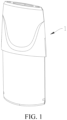
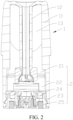
- FIG. 1 to FIG. 2 show a first embodiment of an electronic vaporization device according to the present invention.
- the electronic vaporization device may be applied to vaporization of a vaporized liquid vaporization medium.
- the electronic vaporization device may include a vaporizer and a power supply assembly mechanically and electrically connected to the vaporizer.
- the vaporizer is used to heat and vaporize a liquid medium
- the power supply assembly is used to supply power to the vaporizer.
- the vaporizer and the power supply assembly are detachably connected.
- the vaporizer may include a shell 1 and a vaporization assembly 2.
- the shell 1 may be sleeved over the outer periphery of the vaporization assembly 2.
- the vaporization assembly 2 may be arranged in the shell 1, and may be used to heat and vaporize the liquid vaporization medium.
- the shell 1 may be in a shape of a cylinder.
- An inner side may be a hollow structure, and may include a housing 11 sleeved over the outer periphery of the vaporization assembly 2 and an airflow pipeline 12 provided in the housing 11. Space in the housing 11 and located on an upper part of the vaporization assembly 2 may form a liquid storage cavity 13, which is used to store the liquid vaporization medium.
- the airflow pipeline 12 may be inserted on the vaporization assembly 2, and may be used to output an airflow vaporized by the vaporization assembly 2.
- An air outlet may be provided at one end of the airflow pipeline 12.
- the housing 11 may be integrally formed with the airflow pipeline 12.
- the housing 11 may be integrally formed with the airflow pipeline 12 by injection molding.
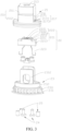
- the vaporization assembly may include a vaporization base 21, a heating component 22, and a base 23.
- the vaporization base 21 may be sleeved above the heating component 22, and may be in communication with the airflow pipeline 12 in the shell 1.
- the vaporization base 21 may accommodate the heating component 22 and form a vaporization cavity 214, thereby forming space for the heating component 22 to heat the liquid vaporization medium, and facilitating output of the formed vapor from the airflow pipeline 12.
- the heating component 22 may be arranged in the vaporization base 21, and may be used to vaporize the vaporization medium in the shell 1.
- the base 23 is assembled with the vaporization base 21, and is used to support the heating component 22.
- the vaporization base 21 may include an outer sleeve 211 and an inner sleeve 212.
- the outer sleeve 211 may be sleeved over the outer periphery of the inner sleeve 212, and the length of the outer sleeve 211 may be greater than the length of the inner sleeve 212.
- the outer sleeve 211 may extend along one end of the inner sleeve 212 and may be sleeved over the base 23.
- the inner sleeve 212 may be embedded in the outer sleeve 211, and the inner sleeve 212 may be integrally formed with the outer sleeve 211. Specifically, in some embodiments, the inner sleeve 212 may be integrally formed with the outer sleeve 211 by injection molding.
- the outer sleeve 211 may include a first sleeve portion 2111 and a second sleeve portion 2112.
- the first sleeve portion 2111 may be sleeved over the heating component 22.
- the first sleeve portion 2111 may be substantially a hollow structure with a narrow top and a wide bottom, and may be substantially in a shape of a rectangular.
- the second sleeve portion 2112 may be arranged at the end of the first sleeve portion 2111.
- the second sleeve portion 2112 may be arranged at a lower end of the first sleeve portion 2111, and the width of the second sleeve portion 2112 may be set greater than the width of the first sleeve portion 2111.
- a cross section of the second sleeve portion 2111 may be substantially in a shape of an ellipse.
- the second sleeve portion 2112 may be sleeved over the base 23, and may be fixedly connected to the base 23 through an interference fit.
- the first sleeve portion 2111 may be integrally formed with the second sleeve portion 2112.
- the first sleeve portion 2111 may be integrally formed with the second sleeve portion 2112 by injection molding.
- the inner sleeve 212 may be sleeved over the heating component 22, and the length of the inner sleeve 212 may be less than the length of the outer sleeve 211, and specifically, may be less than the length of the first sleeve portion 2111.
- the inner sleeve 212 may be substantially in a shape of a bowl, and a size of a cross section of the inner sleeve 212 may be less than a size of a cross section of the outer sleeve 211.
- An inner side of the inner sleeve 212 may be a hollow structure. A gap left between the outer sleeve 211 and the inner sleeve 212 may form an air storage cavity 215, which may be used to collect an airflow delivered from the outside.
- an air outlet channel 213 may be provided on the vaporization base 21, and the air outlet channel 213 may be provided on a top portion of the outer sleeve 211. Specifically, in this embodiment, the air outlet channel 213 may be provided on a top portion of the first sleeve portion 2111 and is in communication with the inner sleeve 22. The air outlet channel 213 may be in communication with the airflow pipeline 12 on the shell 1, and may be used to output vapor generated by the heating component 22 to the airflow pipeline 12.
- a vaporization cavity 214 is provided on an inner side of the vaporization base 21, and the vaporization cavity 214 may be formed in the inner sleeve 212.
- the air outlet channel 213 may be provided in communication with the vaporization cavity 214, and may be used to output the vapor in the vaporization cavity 214.
- the air storage cavity 215 may be located on the outer periphery of the vaporization cavity 214.
- the vaporization cavity 214 may include a first connection portion 2141, a second connection portion 2142, and a third connection portion 2143 that are sequentially arranged.
- the first connection portion 2141 may extend toward the heating component 22.
- the second connection portion 2142 may be arranged at one end of the first connection portion 2141, and may be connected to the first connection portion 2141.
- the third connection portion 2143 may be arranged at one end of the second connection portion 2142, and may extend toward the air outlet channel 213.
- the first connection portion 2141, the second connection portion 2142, and the third connection portion 2143 may be integrally formed.
- the vaporization cavity 214 may be substantially in a shape of a bowl.
- the first connection portion 2141, the second connection portion 2142, and the third connection portion 2143 may all be arc surfaces, so as to reduce airflow resistance and cause the airflow to be more smooth.
- a through hole 216 may be provided on the outer sleeve 211.
- the through hole 216 may be located on two opposite sides of the first sleeve portion 2111, may be provided close to the second sleeve portion 2112, and may be in communication with the air storage cavity 215.
- the through hole 216 may be used for the heating component 22 to pass through.
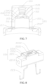
- a vent groove 217 for ventilating a vaporization core 221 is provided on the outer sleeve 211, and the vent groove 217 may be provided on two opposite sides of the outer sleeve 211. Specifically, the air vent groove 217 may be provided on an end surface on which the first sleeve portion 2112 is connected to the second sleeve portion 2111. In this embodiment, the vent groove 217 may be correspondingly provided with the through hole 216. Specifically, the vent groove 217 may be in communication with the through hole 216. In this embodiment, the vent groove 217 may be in a shape of a cross.
- the vent groove 217 may be in a shape of a straight line or in another shape.
- the vent groove 217 may include air outlet grooves 2172, 2173 and air inlet grooves 2171.
- the air outlet grooves 2172, 2173 may include a first air outlet groove 2172 and a second air outlet groove 2173.
- first air outlet grooves 2172 There may be two first air outlet grooves 2172, and the two first air outlet grooves 2172 may be provided side by side and provided in communication with each other, and be cross-provided with the air inlet grooves 2171. There may be one second air outlet groove 2173, and the air outlet groove 2173 and the air inlet grooves 2171 may be distributed in a shape of a straight line.
- first air outlet grooves 2172 when the heating component 22 is mounted in a mounting hole 216, the second air outlet groove 2173 is blocked. As a result, the heating component 22 cannot ventilate normally. It may be understood that in some other embodiments, a quantity of air outlet grooves 2172, 2173 is not limited to three.
- a quantity of air outlet grooves 2172, 2173 may be one or more than three, and a quantity of air inlet grooves 2171 may be one or more.
- ventilation efficiency of the heating component 22 may be improved, and a problem of liquid leakage may be resolved. That is, there is a bending area, which may make it difficult for the vaporization medium to leak downward.
- the heating component 22 may include a vaporization core 221 and a heating element 222; and the heating element 222 may be arranged on the vaporization core 221.
- the heating element 222 may be arranged on the vaporization core 221, and may be used to heat the vaporization medium on the vaporization core 221 to cause the vaporization medium to be vaporized and form vapor.
- the vaporization core 221 may be a ceramic vaporization core. Certainly, it may be understood that in some other embodiments, the vaporization core 221 may not be limited to the ceramic vaporization core.
- the vaporization core 221 may include a liquid guide portion 2211 and a vaporization portion 2212.
- the liquid guide portion 2211 may be substantially in a shape of a rectangular, and may be inserted on the first sleeve portion 2111 of the outer sleeve 211.
- two ends of the liquid guide portion 2211 pass through the through hole 216 to be in liquid guiding connection with the liquid storage cavity 13 of the shell 1, and may inhale the liquid vaporization medium.
- a liquid guide hole 2213 used to introduce the vaporization medium in the liquid storage cavity 13 may be provided on the liquid guide portion 2211, and the liquid guide hole 2213 may be provided along the length direction of the liquid guide portion 2211.
- the vaporization portion 2212 may protrude from the liquid guide portion 2211.
- the vaporization portion 2212 may be in a shape of a rectangular, and the length of the vaporization portion 2212 may be less than the length of the liquid guide portion 2211.
- the vaporization portion 2212 may be integrally formed with the liquid guide portion 2211.
- the inner sleeve 212 may be sleeved over the vaporization portion 2212, and may be fixedly connected to the vaporization portion 2212 through an interference fit.
- the vaporization cavity 214 may be formed in the inner sleeve 212 and be located in upper space of the vaporization portion 2212.
- the heating component 22 may include a vaporization surface 2214.
- the vaporization surface 2214 may be formed on the vaporization portion 2212 of the vaporization core 221, and may be arranged facing the air outlet channel 213.
- the heating element 222 may be arranged on the vaporization surface 2214.
- the heating element 222 may be a heating film, and the heating film may be fixed on the vaporization surface 2214 by sintering.
- the heating element 222 may not be limited to the heating film.
- the heating element 222 may be a heating sheet.
- the heating element 222 may include a bent portion 2221 and a straight portion 2222.
- the bent portion 2221 may be in two sections, the bent portion 2221 may be located on two opposite sides, and may be connected by the straight portion 2222.
- the straight portion 2222 may be in three sections, and one end of the straight portion 2222 may be connected to the bent portion 2221.
- the bent portion 2221 increases internal resistance through bending so that the temperature of the bent portion 2221 is higher than the temperature of the straight portion 2222 in an energized state, and the temperature in a corner area of the bent portion 2221 is the highest temperature.
- the heating component 22 may further include conductive connection portions 223. There may be two conductive connection portions 223. The two conductive connection portions 223 may be respectively connected to two ends of the heating element 222, and may pass through the vaporization core 221 to be electrically connected to an electrode member 24. In this embodiment, the conductive connection portion 223 may be a lead.
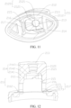
- the air guide structure 2120 may be arranged on the vaporization base 21.
- the air guide structure 2120 may be used to guide the airflow in an air flow path, and guide the airflow to the vaporization surface 2214 on the heating component 22.
- the vaporized vapor on the vaporization surface 2214 may be directly guided into the air outlet channel 213 through the air guide structure 2120, thereby increasing an amount of vaporized vapor.
- the air guide structure 2120 may be arranged on an end surface of the inner sleeve 21 facing the vaporization surface 2214, and a set distance D may be left between the air guide structure 2120 and the vaporization surface 2214.
- the air guide direction of the air guide structure 2120 may be set to align with the position of the highest temperature on the heating element 222, that is, set to align with the bent portion 2221, so that vapor from an area that generates the largest amount of vapor may be exported, thereby increasing the amount of exported vapor.
- the air guide structure 2120 may include two air guide grooves 2121.
- the two air guide grooves 2121 may be provided on the end surface of the inner sleeve 212 facing the vaporization surface 2214, may be distributed on two opposite sides of the vaporization surface 2214, and may be provided in parallel.
- the two air guide grooves 2121 may not be on the same straight line, so that the introduced airflow does not form a confrontation, thereby causing the vapor to disperse. It may be understood that in some other embodiments, the two air guide grooves 2121 may not be limited to being provided in parallel, nor be limited to being not on the same straight line.
- the two air guide grooves 2121 may be provided opposite to each other and located on a straight line. It may be understood that, in some embodiments, a quantity of air guide grooves 2121 may not be limited to two. In some other embodiments, a quantity of air guide grooves 2121 may be one or more than two.
- a set distance D may be left between the air guide groove 2121 and the vaporization surface 2214.
- a plane on which the air guide groove 2121 is located may be arranged slightly higher than the vaporization surface 2214, and the set distance D of the air guide groove 2121 may range from 0.5 mm to 1.5 mm.
- the air guide direction of the air guide groove 2121 may be set to align with the position of the highest temperature on the heating element 222, that is, may be set to align with the bent portion 2221.
- the air inlet area of a single air guide groove 2121 may range from 0.6 mm 2 to 1.5 mm 2 .
- the air inflow is insufficient; and when the air inlet area is greater than 1.5 mm 2 , vapor dispersion occurs and the amount of vapor decreases.
- a sum of air inlet areas of the two air guide grooves 2121 may range from 0.8 mm 2 to 3.0 mm 2 , so that the air inflow may be increased, and then the amount of the vaporized vapor may be increased.
- the base 23 may include a base body 231, and a matching portion 232 arranged on the base body 231 and matching with the vaporization base 21.
- a cross section of the base body 231 may be substantially in a shape of an ellipse.
- the base body 231 may be inserted from an open end of the shell 1, and may block the opening of the shell 1.
- the base body 231 may not be limited to be in a shape of an ellipse.
- the base body 231 may be in snap-fit connection to the shell 1.
- buckles 2311 may be arranged on two side walls that are arranged opposite to each other of the base body 231, and the base body 231 may be in snap-fit connection to the shell 1 through the buckles 2311.
- an air inlet 2312 may be provided on the base 23.
- the air inlet 2312 may be provided on the base body 231, and there may be two air inlets 2312.
- the two air inlets 2312 may be distributed on a short axis of the base body 231, and are in communication with the air storage cavity 215 respectively.
- a first through hole 2313 may further be provided on the base body 231, and there may be two first through holes 2313.
- the two first through holes 2313 may be provided at intervals, so that two electrode members 24 may be mounted on the two first through holes 2313 in a one-to-one correspondence manner.
- two second through holes 2313 may further be provided on the base body 231.
- the two second through holes 2312 may be located on two opposite sides of the two first through holes 2313, so that magnetic members 25 may be mounted on the two second through holes 2312.
- the matching portion 232 may be arranged at one end of the base body 231, so that the second sleeve portion 2112 of the vaporization base 21 may be sleeved over the matching portion 232.
- a support structure 2312 may further be arranged at one end of the matching portion 232.
- the support structure 2312 may be inserted into the vaporization base 231, and may be used to support the heating component 22.
- the support structure 2312 may include two support arms that are arranged opposite to each other. The two support arms may be respectively inserted from the vaporization base 21, and may be located on two opposite sides of the heating component 22.
- the vaporization assembly 2 may further include electrode members 24, and there may be two electrode members 24.
- the two electrode members 24 may be electrically connected to the two conductive connection portions 223 on the heating component 22 respectively in a one-to-one correspondence manner.
- the two electrode members 24 may be mounted in the first through hole 2313 in a one-to-one correspondence manner, so that the heating component 22 may be connected to the power supply assembly.
- the vaporization assembly 2 may further include magnetic members 25, and there may be two magnetic members 25.
- the two magnetic members 25 may be mounted in the two second through holes 2314 in a one-to-one correspondence manner, and may attract and fix the entire vaporizer with the power supply assembly.
- FIG. 10 to FIG. 12 show the second embodiment of the electronic vaporization device of the present invention, which is different from the first embodiment in that the two air guide grooves 2121 are provided in parallel and are located on a straight line.
- a shape of the vaporization cavity 214 is different.
- the vaporization cavity 214 may be substantially in a shape of a rectangular with rounded corners.
- the first connection portion 2141 may be a plane
- the second connection portion 2142 may be an arc surface
- the third connection portion 2143 may be a plane.
- a flow direction of the airflow may be changed by using vaporization cavities of different shapes.
- the airflow of the first embodiment is smoother.
- a structure of an inlet adaptation section and a structure of the air outlet channel 213 are substantially the same, but a design of the vaporization cavity 214 is different.
- a main difference is that the airflow enters the vaporization cavity 214 from the adaptation section (the second connection portion 2142) at a different velocity horizontal angle, and a shape of the adaptation section (the second connection portion 2142) from the vaporization cavity 214 to the air outlet channel 213 is different, so that uniformity and fluidity of the airflow are different.
- inhalation resistance of the airflow channel in the first embodiment and the second embodiment is mainly caused by two parts: the air inlet channel and the adaptation section (the second connection portion 2142) entering the vaporization cavity 214; and the inhalation resistance of the first embodiment is 713.5 Pa, and the inhalation resistance of the second embodiment is 918.3 Pa.
- the inhalation resistance of the second embodiment increases by 28.7%.
- a main reason for the small inhalation resistance of the first embodiment is that a cross-sectional area of an inlet channel of the vaporization cavity 214 is relatively large. The local resistance loss of the air entering the vaporization cavity 214 is small, and the airflow channel at the outlet of the vaporization cavity 214 is smoother, generating a small vortex and less resistance loss.
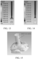
- a vortex in an area 1 causes an increase in the inhalation resistance of the airflow channel and intensifies condensation of vapor.
- a vortex in an area 2 causes a vaporization medium to not be taken away in time, and the temperature of the heating element is too high.
- the two air guide grooves 2121 of the vaporization cavity 214 of the second embodiment are on the same straight line, after the air enters the vaporization cavity 214 from the two air inlets, a "stagnation area" appears at the heating element in the middle, a large vortex (as shown in a dotted box in the foregoing figure) is generated. Most of the airflow is not fully diffused in the vaporization cavity 214, and directly flows out to the air outlet channel.
- the air guide grooves 2121 of the first embodiment are staggered with each other, so that the air enters the vaporization cavity 214 and fully diffuses. Velocity distribution in a heating element area is more uniform, and the air may be fully mixed with the vaporized liquid vaporization medium and then flow out of the vaporization cavity 214.
- the airflow in the first embodiment is more uniformly mixed and the flow is smoother.
Landscapes
- Disinfection, Sterilisation Or Deodorisation Of Air (AREA)
- Nozzles (AREA)
- Electrostatic Spraying Apparatus (AREA)
Applications Claiming Priority (2)
| Application Number | Priority Date | Filing Date | Title |
|---|---|---|---|
| CN202110090068.3A CN112790434A (zh) | 2021-01-22 | 2021-01-22 | 电子雾化装置及其雾化器和雾化组件 |
| PCT/CN2021/133704 WO2022156363A1 (zh) | 2021-01-22 | 2021-11-26 | 电子雾化装置及其雾化器和雾化组件 |
Publications (2)
| Publication Number | Publication Date |
|---|---|
| EP4268635A1 true EP4268635A1 (de) | 2023-11-01 |
| EP4268635A4 EP4268635A4 (de) | 2024-05-29 |
Family
ID=75811278
Family Applications (1)
| Application Number | Title | Priority Date | Filing Date |
|---|---|---|---|
| EP21920739.6A Pending EP4268635A4 (de) | 2021-01-22 | 2021-11-26 | Elektronische zerstäubungsvorrichtung und zerstäuber und zerstäubungsanordnung dafür |
Country Status (4)
| Country | Link |
|---|---|
| US (1) | US20240016224A1 (de) |
| EP (1) | EP4268635A4 (de) |
| CN (1) | CN112790434A (de) |
| WO (1) | WO2022156363A1 (de) |
Families Citing this family (9)
| Publication number | Priority date | Publication date | Assignee | Title |
|---|---|---|---|---|
| CN112790434A (zh) * | 2021-01-22 | 2021-05-14 | 深圳麦克韦尔科技有限公司 | 电子雾化装置及其雾化器和雾化组件 |
| WO2022241609A1 (zh) * | 2021-05-17 | 2022-11-24 | 深圳麦克韦尔科技有限公司 | 雾化座、雾化器及电子雾化装置 |
| CN115606858A (zh) * | 2021-07-16 | 2023-01-17 | 深圳麦克韦尔科技有限公司 | 电子雾化装置及其雾化器和雾化组件 |
| CN115836746A (zh) * | 2021-09-18 | 2023-03-24 | 深圳市合元科技有限公司 | 雾化器及电子雾化装置 |
| CN116406838A (zh) * | 2021-12-30 | 2023-07-11 | 深圳麦克韦尔科技有限公司 | 电子雾化装置及其雾化器 |
| CN114468358A (zh) * | 2022-01-17 | 2022-05-13 | 海南摩尔兄弟科技有限公司 | 电子雾化装置及其雾化器 |
| CN116491693A (zh) * | 2022-01-21 | 2023-07-28 | 深圳市卓力能技术有限公司 | 一种雾化器 |
| WO2023240511A1 (zh) * | 2022-06-15 | 2023-12-21 | 海南摩尔兄弟科技有限公司 | 电子雾化装置及雾化器 |
| US12207686B1 (en) | 2024-09-06 | 2025-01-28 | My Next Idea, LLC | Vortexer for cap of personal vaporizer |
Family Cites Families (14)
| Publication number | Priority date | Publication date | Assignee | Title |
|---|---|---|---|---|
| RU2681342C2 (ru) * | 2015-01-22 | 2019-03-06 | Фонтем Холдингс 1 Б.В. | Электронные испарительные устройства |
| HUE062909T2 (hu) * | 2015-07-09 | 2023-12-28 | Philip Morris Products Sa | Fûtõelrendezés egy aeroszolképzõ rendszerhez |
| AU2016325726A1 (en) * | 2015-09-25 | 2018-04-12 | Lubby Holdings Llc | Personal vaporizer having reversing air flow |
| US11825883B2 (en) * | 2018-07-16 | 2023-11-28 | Lubby Holdings, LLC | Personal vaporizer |
| CN209376696U (zh) * | 2018-11-29 | 2019-09-13 | 深圳市合元科技有限公司 | 电子烟雾化器及包含该电子烟雾化器的电子烟 |
| WO2020258079A1 (zh) * | 2019-06-26 | 2020-12-30 | 深圳麦克韦尔股份有限公司 | 雾化器及电子雾化装置 |
| CN211211432U (zh) * | 2019-10-30 | 2020-08-11 | 深圳市合元科技有限公司 | 雾化组件及电子烟 |
| CN210929638U (zh) * | 2019-08-09 | 2020-07-07 | 常州市派腾电子技术服务有限公司 | 雾化器及气溶胶发生装置 |
| CN110623308B (zh) * | 2019-09-29 | 2025-07-08 | 深圳麦克韦尔科技有限公司 | 电子雾化装置及其雾化器 |
| CN211482973U (zh) * | 2019-11-26 | 2020-09-15 | 深圳市合元科技有限公司 | 雾化组件及电子烟 |
| CN111011932B (zh) * | 2019-12-26 | 2025-03-21 | 深圳麦克韦尔科技有限公司 | 电子雾化装置及其雾化器 |
| CN111466614A (zh) * | 2020-04-02 | 2020-07-31 | 深圳麦克韦尔科技有限公司 | 雾化芯、雾化器和电子雾化装置 |
| CN214854326U (zh) * | 2021-01-22 | 2021-11-26 | 深圳麦克韦尔科技有限公司 | 电子雾化装置及其雾化器和雾化组件 |
| CN112790434A (zh) * | 2021-01-22 | 2021-05-14 | 深圳麦克韦尔科技有限公司 | 电子雾化装置及其雾化器和雾化组件 |
-
2021
- 2021-01-22 CN CN202110090068.3A patent/CN112790434A/zh active Pending
- 2021-11-26 EP EP21920739.6A patent/EP4268635A4/de active Pending
- 2021-11-26 WO PCT/CN2021/133704 patent/WO2022156363A1/zh not_active Ceased
-
2023
- 2023-07-20 US US18/356,154 patent/US20240016224A1/en active Pending
Also Published As
| Publication number | Publication date |
|---|---|
| CN112790434A (zh) | 2021-05-14 |
| WO2022156363A1 (zh) | 2022-07-28 |
| EP4268635A4 (de) | 2024-05-29 |
| US20240016224A1 (en) | 2024-01-18 |
Similar Documents
| Publication | Publication Date | Title |
|---|---|---|
| EP4268635A1 (de) | Elektronische zerstäubungsvorrichtung und zerstäuber und zerstäubungsanordnung dafür | |
| CN221128829U (zh) | 电子雾化装置及其雾化器 | |
| CN113273732B (zh) | 雾化器及其应用的出气通道插件、电子雾化装置 | |
| US11910835B2 (en) | Electronic atomizing device and atomizer thereof | |
| CN114468357A (zh) | 电子雾化装置及其雾化器 | |
| CN214854326U (zh) | 电子雾化装置及其雾化器和雾化组件 | |
| CN217218193U (zh) | 雾化器及气溶胶产生装置 | |
| CN218551287U (zh) | 一种电子雾化装置 | |
| WO2021184943A1 (zh) | 传感器密封件及电子烟 | |
| WO2021227742A1 (zh) | 雾化器及其气溶胶发生装置 | |
| CN217826755U (zh) | 防渗漏雾化器及电子雾化装置 | |
| CN116584703A (zh) | 一种气溶胶生成装置 | |
| WO2023039777A1 (zh) | 雾化器及雾化装置 | |
| CN220236041U (zh) | 雾化器及电子雾化装置 | |
| CN219939717U (zh) | 雾化器及电子雾化装置 | |
| CN219069462U (zh) | 雾化器及气溶胶生成装置 | |
| CN115191662A (zh) | 电子雾化装置及雾化器和支撑结构 | |
| CN215224745U (zh) | 电子雾化装置及其雾化器和雾化组件 | |
| CN215347019U (zh) | 一种雾化器及气溶胶生成装置 | |
| CN116172252A (zh) | 雾化器及气溶胶生成装置 | |
| CN115191663A (zh) | 电子雾化装置及雾化器和支撑结构 | |
| CN219613033U (zh) | 雾化器及电子雾化装置 | |
| WO2022199546A1 (zh) | 雾化器及电子雾化装置 | |
| CN219939714U (zh) | 雾化器及电子雾化装置 | |
| CN223773128U (zh) | 加热基座组件和雾化设备 |
Legal Events
| Date | Code | Title | Description |
|---|---|---|---|
| STAA | Information on the status of an ep patent application or granted ep patent |
Free format text: STATUS: THE INTERNATIONAL PUBLICATION HAS BEEN MADE |
|
| PUAI | Public reference made under article 153(3) epc to a published international application that has entered the european phase |
Free format text: ORIGINAL CODE: 0009012 |
|
| STAA | Information on the status of an ep patent application or granted ep patent |
Free format text: STATUS: REQUEST FOR EXAMINATION WAS MADE |
|
| 17P | Request for examination filed |
Effective date: 20230724 |
|
| AK | Designated contracting states |
Kind code of ref document: A1 Designated state(s): AL AT BE BG CH CY CZ DE DK EE ES FI FR GB GR HR HU IE IS IT LI LT LU LV MC MK MT NL NO PL PT RO RS SE SI SK SM TR |
|
| REG | Reference to a national code |
Ref country code: DE Ref legal event code: R079 Free format text: PREVIOUS MAIN CLASS: A24F0040400000 Ipc: A24F0040485000 |
|
| DAV | Request for validation of the european patent (deleted) | ||
| DAX | Request for extension of the european patent (deleted) | ||
| A4 | Supplementary search report drawn up and despatched |
Effective date: 20240502 |
|
| RIC1 | Information provided on ipc code assigned before grant |
Ipc: A24F 40/10 20200101ALI20240426BHEP Ipc: A24F 40/46 20200101ALI20240426BHEP Ipc: A24F 40/485 20200101AFI20240426BHEP |
|
| RAP3 | Party data changed (applicant data changed or rights of an application transferred) |
Owner name: SHENZHEN SMOORE TECHNOLOGY LIMITED |
|
| RAP3 | Party data changed (applicant data changed or rights of an application transferred) |
Owner name: SHENZHEN SMOORE TECHNOLOGY LIMITED |
|
| STAA | Information on the status of an ep patent application or granted ep patent |
Free format text: STATUS: EXAMINATION IS IN PROGRESS |
|
| 17Q | First examination report despatched |
Effective date: 20250620 |