EP4249414B1 - Yarn winding machine - Google Patents
Yarn winding machine Download PDFInfo
- Publication number
- EP4249414B1 EP4249414B1 EP23163013.8A EP23163013A EP4249414B1 EP 4249414 B1 EP4249414 B1 EP 4249414B1 EP 23163013 A EP23163013 A EP 23163013A EP 4249414 B1 EP4249414 B1 EP 4249414B1
- Authority
- EP
- European Patent Office
- Prior art keywords
- bobbin
- yarn
- bobbin holder
- package
- wound
- Prior art date
- Legal status (The legal status is an assumption and is not a legal conclusion. Google has not performed a legal analysis and makes no representation as to the accuracy of the status listed.)
- Active
Links
Images


Classifications
-
- B—PERFORMING OPERATIONS; TRANSPORTING
- B65—CONVEYING; PACKING; STORING; HANDLING THIN OR FILAMENTARY MATERIAL
- B65H—HANDLING THIN OR FILAMENTARY MATERIAL, e.g. SHEETS, WEBS, CABLES
- B65H67/00—Replacing or removing cores, receptacles, or completed packages at paying-out, winding, or depositing stations
- B65H67/04—Arrangements for removing completed take-up packages and or replacing by cores, formers, or empty receptacles at winding or depositing stations; Transferring material between adjacent full and empty take-up elements
- B65H67/044—Continuous winding apparatus for winding on two or more winding heads in succession
- B65H67/048—Continuous winding apparatus for winding on two or more winding heads in succession having winding heads arranged on rotary capstan head
-
- B—PERFORMING OPERATIONS; TRANSPORTING
- B65—CONVEYING; PACKING; STORING; HANDLING THIN OR FILAMENTARY MATERIAL
- B65H—HANDLING THIN OR FILAMENTARY MATERIAL, e.g. SHEETS, WEBS, CABLES
- B65H65/00—Securing material to cores or formers
-
- B—PERFORMING OPERATIONS; TRANSPORTING
- B65—CONVEYING; PACKING; STORING; HANDLING THIN OR FILAMENTARY MATERIAL
- B65H—HANDLING THIN OR FILAMENTARY MATERIAL, e.g. SHEETS, WEBS, CABLES
- B65H2408/00—Specific machines
- B65H2408/20—Specific machines for handling web(s)
- B65H2408/23—Winding machines
- B65H2408/231—Turret winders
- B65H2408/2315—Turret winders specified by number of arms
- B65H2408/23152—Turret winders specified by number of arms with two arms
-
- B—PERFORMING OPERATIONS; TRANSPORTING
- B65—CONVEYING; PACKING; STORING; HANDLING THIN OR FILAMENTARY MATERIAL
- B65H—HANDLING THIN OR FILAMENTARY MATERIAL, e.g. SHEETS, WEBS, CABLES
- B65H2701/00—Handled material; Storage means
- B65H2701/30—Handled filamentary material
- B65H2701/31—Textiles threads or artificial strands of filaments
- B65H2701/313—Synthetic polymer threads
- B65H2701/3132—Synthetic polymer threads extruded from spinnerets
Definitions
- the present invention relates to a yarn winding machine provided with a plurality of bobbin holders.
- Patent Literature 1 is Japanese Patent Application Publication No. 2001-019274 .
- a spinning winding machine disclosed in Patent Literature 1 produces a package by winding a yarn on a bobbin.
- the spinning winding machine includes two bobbin holders and a turret. A plurality of bobbins are attached to each of the two bobbin holders. Two bobbin holders are attached to the turret. The position of the bobbin holder changes between a winding position, a standby position, and a yarn switching position by rotation of the turret. While one bobbin holder is positioned at the winding position to produce the package, the other bobbin holder is positioned at the standby position. After the yarn winding is completed, the two bobbin holders are positioned at the yarn switching positions by rotation of the turret. Next, the spinning winding machine switches from a state of winding the yarn on the bobbin of one bobbin holder to a state of winding the yarn on the bobbin of the other bobbin holder by operating a slide guide.
- the spinning winding machine of Patent Literature 1 sets the position of one bobbin holder to the position of the full package at the time of yarn switching, in other words a position shifted 90° clockwise from the winding position in order to thread the yarn on the bobbin of one bobbin holders before starting package produce.
- a yarn winding machine having two winding units arranged upper and lower for producing a package by winding a yarn fed from a yarn feeding roller, it is necessary to avoid interference between a bobbin holder of the upper yarn winding unit and the yarn heading for the lower yarn winding unit from the yarn feed roller. Therefore, it is necessary to be largely offset the lower winding unit with respect to the upper winding unit. As a result, the installation area of the yarn winding machine becomes large, and there is room for improvement.
- EP 2 664 570 A1 presents a spun yarn winding device and spun yarn winding facility.
- a spun yam winding device is compacted in a vertical direction provided with: a machine body; a turret; a feeding roller fixed to the machine body, is not in contact with the winding bobbins and feeds yarns to the winding bobbins at a speed equal to or faster than the winding speed; a traverse device is fixed in upstream side of advance direction of the yarns relative to the feeding roller and which traverses the yarns; a peripheral speed detection unit detecting the peripheral speed of the winding bobbins; and a control unit performing basic operation for maintaining the free length of the yarns at a standard length by controlling the rotational angle of the turret during a yam winding period, the free length of the yarns located between the feeding roller and the winding bobbins.
- the present invention has been made in view of the above circumstances, and a primary object thereof is to provide a configuration with a small installation area in a yarn winding machine having two winding units arranged at upper and lower for producing a package by winding a yarn fed from a yarn feed roller.
- the yarn winding machine includes a lower winding unit and an upper winding unit.
- the lower winding unit winds a yarn fed from a yarn feed roller to produce a package.
- the upper winding unit is arranged at a higher position than the lower winding unit and at an offset position perpendicular to an axial direction of the package with respect to the lower winding unit in the plan view, and the upper winding unit winds the yarn fed from the yarn feed roller to produce the package.
- the upper winding unit includes a first bobbin holder, a second bobbin holder, a bobbin holder moving mechanism, and a contact roller.
- the first bobbin holder holds the first bobbin.
- the second bobbin holder holds the second bobbin.
- the first bobbin holder and the second bobbin holder are attached to the bobbin holder moving mechanism, and the bobbin holder moving mechanism changes a position of the first bobbin holder and the second bobbin holder by rotating around a rotation axis parallel to the axial direction of the package.
- the contact roller rotates in contact with the first bobbin, the second bobbin, or the package when producing the package.
- a position where the first bobbin, the second bobbin, or the package contact with the contact roller and the yarn is wound on the first bobbin or the second bobbin to produce the package is defined as 0° or 360°.
- a rotation direction of rotating from 0° toward an offset direction in which the upper winding unit is offset with respect to the lower winding unit is defined as positive.
- the bobbin holder moving mechanism sets the position of the first bobbin holder to a position larger than 270° and smaller than 360° by receiving a signal for threading the yarn to the first bobbin.
- the offset amount in which the upper winding unit is offset with respect to the lower winding unit can be reduced, and the installation area of the yarn winding machine can be reduced.
- the bobbin holder moving mechanism after receiving a signal for threading the yarn on the first bobbin, the bobbin holder moving mechanism preferably sets the position of the first bobbin holder to a position larger than 290° and smaller than 340°.
- the yarn threading of the upper winding unit can be performed at a position farther from the yarn path of the lower winding unit and at a position where the possibility of contact between the yarn and the contact roller is further reduced.
- the bobbin holder moving mechanism preferably sets a position of one of the first bobbin holder and the second bobbin holder to 180° and sets the other position to 0°.
- the yarn switching can be performed in a state where the first bobbin and the second bobbin are positioned far from the yarn path of the lower winding unit.
- the bobbin holder moving mechanism preferably rotates so that positions of the first bobbin holder and the second bobbin holder are changed only in the positive direction from the state where the yarn is threaded on the first bobbin to the state where the yarn is wound on the second bobbin to produce the package.
- Control of the bobbin holder moving mechanism can be simplified.
- the offset amount can be reduced.
- the yarn winding machine described above preferably has the following configuration. That is, by receiving a signal for threading the yarn on the first bobbin, a position of the first bobbin holder is set to the position larger than 270° and smaller than 360°, and then by receiving a signal indicating a completion of an operation of threading the yarn to the first bobbin, a position of the first bobbin holder is set to a position greater than 0° and less than 180°.
- the upper winding unit preferably includes a windbreak plate for preventing accompanying flow generated by a rotation of the package formed on the first bobbin holder or the second bobbin holder from affecting the yarn wound at the lower winding unit.
- the yarn wound on the second bobbin when the package formed on the second bobbin is fully wound, in a state where the bobbin holder moving mechanism sets a position of the first bobbin holder to a position of less than ⁇ 45° with respect to 0°, the yarn wound on the second bobbin preferably switched to be wound on the first bobbin.
- the fully wound package does not pass through a range close to the yarn path to the lower winding unit. Therefore, it is possible to further reduce the offset amount of the upper winding unit. In addition, the operation of winding the yarn connected to the package on the first bobbin can be easily performed.
- FIG. 1 is a front view of a yarn winding machine 1 according to an embodiment of the present invention.
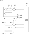
- FIG. 2 is a block diagram of the yarn winding machine 1.
- upstream or downstream in a yarn running direction may simply be referred to as “upstream” or “downstream”.
- An unillustrated spinning machine is arranged upstream of the yarn winding machine 1 illustrated in FIG. 1 .
- a yarn 93 produced by the spinning machine is supplied to the yarn winding machine 1 via a yarn feed roller.
- the yarn winding machine 1 winds the yarn 93 on bobbins 91, 92 and form yarn layers to produce packages 94.
- the yarn 93 is an elastic yarn such as spandex.
- the type of yarn 93 is not limited to that yarn, and a synthetic yarn including nylon, polyester, or the like may be used.
- the yarn winding machine 1 includes an upper winding unit 10a and a lower winding unit 10b.
- the yarn 93 is separately fed to each of the upper winding unit 10a and the lower winding unit 10b from the common yarn feed roller 100, and the packages 94 are separately produced at the upper winding unit 10a and the lower winding unit 10b
- the yarn 93 includes a plurality of the yarns 93, and each of the winding unit 10 is supplied with the plurality of yarns 93 arranged in the axial direction of the package 94.
- Each of the winding unit 10 winds each of the plurality of yarns 93 to produce the plurality of package 94.
- the upper winding unit 10a and the lower winding unit 10b are basically provided with the same device. Therefore, the upper winding unit 10a will be described below as a representative. As illustrated in FIG. 1 , the upper winding unit 10a includes a frame 11, a first housing 20, a second housing 30, and a turret plate (bobbin holder moving mechanism) 40.
- the frame 11 is a member that holds each component provided in the upper winding unit 10a.
- the first housing 20 is attached with a traverse device 21.
- the traverse device 21 reciprocating in a winding width direction (axial direction of the package 94) with a traverse guide 23 described later being engaged with the yarn 93, each yarn 93 forwarded downstream is traversed.
- the traverse device 21 includes a traverse cam 22, the traverse guide 23, and a traverse motor 24.
- FIG. 2 shows a block diagram of one winding unit (upper winding unit 10a or lower winding unit 10b).
- the traverse cam 22 is a roller-shaped member arranged parallel to the bobbin 91, 92. A spiral cam groove is formed on an outer peripheral surface of the traverse cam 22.
- the traverse cam 22 is rotationally driven by a traverse motor 24.
- the traverse guide 23 is a part that engages the yarn 93.
- a distal end of the traverse guide 23 includes, for example, a substantially U-shaped guide part that engages with the yarn 93 while sandwiching the yarn 93 in the winding width direction.
- a proximal end of the traverse guide 23 is positioned in a cam groove of the traverse cam 22. When the traverse cam 22 is rotationally driven, it is possible to reciprocate the traverse guide 23 in the winding width direction.
- the traverse motor 24 is controlled by a control device 50.
- the control device 50 includes a CPU, a ROM, and a RAM.
- the CPU executes various controls related to the upper winding unit 10a by reading a program stored in the ROM into the RAM and executing such a program.
- the second housing 30 is rotatably attached with a contact roller 31.
- the contact roller 31 is driven to rotate with a contact with the yarn layer of the package 94 with a certain pressure to form a yarn layer shape of the package 94 into a shape.
- An operation panel 32 is provided on the second housing 30.
- the operation panel 32 is a device operated by an operator.
- the operator applies an instruction to the upper winding unit 10a by operating the operation panel 32. Examples of the instruction applied by the operator include starting yarn threading, starting winding, stopping winding, and changing a winding condition.
- the upper winding unit 10a includes a lifting and lowering device 60.
- the lifting and lowering device 60 lifts and lowers the first housing 20 and the second housing 30 altogether.
- the first housing 20 and the second housing 30 are attached to an unillustrated lifting and lowering member.
- a ball nut 61 is attached to the lifting and lowering member.
- a screw rod 62 is attached to the frame 11.
- the lifting and lowering motor 63 is controlled by the control device 50. It is noted that the lifting and lowering device 60 may be realized by using a cylinder instead of the ball screw.
- the turret plate 40 is a disk-shaped member.
- the turret plate 40 is rotatably attached to the frame 11.
- a rotation axis of the turret plate 40 is at a center position of the turret plate 40.
- the turret plate 40 is rotationally driven by a turret motor 53 illustrated in FIG. 2 .
- the turret motor 53 is controlled by the control device 50.
- a first bobbin holder 41 and a second bobbin holder 42 are each provided.
- the first bobbin holder 41 is attachable with the first bobbin 91 including a plurality of the first bobbins 91 to be aligned in the axial direction.
- the second bobbin holder 42 is attachable with the second bobbin 92 including a plurality of the second bobbins 92 to be aligned in the axial direction.
- the first bobbin holder 41 is rotatable with respect to the turret plate 40 with the axial position of the first bobbin holder 41 being the center of rotation.
- the first bobbin holder 41 is rotationally driven by a first bobbin holder motor 54 illustrated in FIG. 2 .
- the second bobbin holder 42 is rotatable with respect to the turret plate 40 with the axial position of the second bobbin holder 42 being the center of rotation.
- the second bobbin holder 42 is rotationally driven by a second bobbin holder motor 55 illustrated in FIG. 2 .
- the first bobbin holder motor 54 and the second bobbin holder motor 55 are controlled by the control device 50.
- the yarn 93 is wound on a first bobbin of the first bobbin holder 41 at a higher position to produce the package 94.
- a bobbin attached to the first bobbin holder 41 is referred to as a first bobbin 91
- a bobbin attached to the second bobbin holder 42 is referred to as a second bobbin 92.
- the turret plate 40 rotates to switch the positions of the first bobbin holder 41 and the second bobbin holder 42. Thereafter, while the package 94 in which the full winding is achieved is collected, the yarn 93 is wound on the second bobbin 92 attached to the second bobbin holder 42.
- the one ends (turret plate 40 side ends) of the bobbin holders 41, 42 are supported to the turret plate 40.
- the yarn winding machine 1 further includes a support member 74 that supports the other ends (the ends opposite to the turret plate 40) of the bobbin holders 41, 42 positioned for producing the package 94.
- the bobbin holders 41, 42 of the upper winding upper winding unit 10a pass through the vicinity of the yarn 93 from the yarn feed roller 100 to the lower winding unit 10b by the rotation of the turret plate 40. Also, the accompanying flow is generated by the rotation of the package 94 formed on the bobbin holders 41, 42 of the upper winding unit 10a.
- a windbreak plate 75 is provided with the upper winding unit 10a in order to suppress the accompanying flow from acting on the yarn 93 wound on the lower winding unit 10b.
- the windbreak plate 75 is not provided with the lower winding unit 10b.
- the windbreak plate 75 may be omitted from the upper winding unit 10a.
- the yarn threading operation is an operation in which the operator winds the yarn 93 on the bobbins 91, 92 in a prior step to producing the package 94.
- the waste winding is an operation to wind the yarn 93 having a low quality at the start of winding, which is performed after the yarn threading operation.
- the yarn 93 that has been wound up by the waste winding is discarded.
- the reason why the yarn 93 has low quality is as follows. That is, at the step of the yarn threading by the operator, the yarn 93 is wound in a state in which the yarn 93 is not engaged with the traverse guide 23. Also, the traverse guide 23 is driven at a lower speed than usual. Therefore, even if the yarn 93 is engaged with the traverse guide 23 after the yarn threading, the quality of the yarn 93 is low until the traverse guide 23 reaches the normal speed.
- the winding width direction, the axial direction of the package 94, and the axial directions of the bobbin holders 41, 42 are all parallel. In the description below, these directions are collectively referred to simply as the "axial direction".
- the direction in which the yarn feed roller 100 is positioned with respect to the yarn winding machine 1 is referred to as the "height direction”.
- the side closer to the yarn feed roller 100 in the height direction is referred to as an upper side, and the opposite side is referred to as a lower side.
- a direction perpendicular to both the axial direction and the height direction is referred to as a "direction perpendicular to the axis".
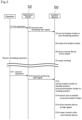
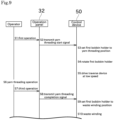
- the operator performs a predetermined first operation on the operation panel 32 (S1).
- the first operation is an operation for notifying the yarn winding machine 1 that the yarn threading operation is to be performed.
- the first operation is to operate a predetermined button on the operation panel 32, for example.
- the operation panel 32 transmits a yarn threading start signal to the control device 50 (S2).
- the yarn threading start signal is an electrical signal that is transmitted to the control device 50 by performing the first operation on the operation panel 32.
- the yarn threading start signal may be referred to as a signal for threading the yarn to the first bobbin 91.
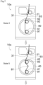
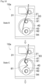
- the control device 50 controls the turret motor 53 to rotate the turret plate 40 counterclockwise, thereby setting the first bobbin holder 41 at the yarn threading position (S3, from state 1 to state 2 in FIG. 5 ).
- the yarn threading position is a position of the first bobbin holder 41 when the operator performs the yarn threading operation.
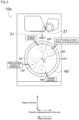
- each position of the bobbin holders 41, 42 will be described with reference to FIG. 4 .
- the higher position of the bobbin holder 41, 42 is the winding position and the lower position of the bobbin holder 41, 42 is the standby position.
- the yarn winding machine 1 winds the yarn 93 on the bobbins 91, 92 of the bobbin holders 41, 42 at the winding position to produce the package 94.
- the winding position is a position where the bobbins 91, 92 of the bobbin holders 41, 42 or the package 94 contacts the contact roller 31.
- a center of rotation of the turret plate 40 is referred to as a point C.
- the position of the bobbin holders 41, 42 (more specifically, the positions of the axes of the bobbin holders 41, 42) is expressed using an angle with the point C as a reference (center), as follows. That is, the winding position is 0° (or 360°) and the standby position is 180°. As illustrated in FIG. 4 , the direction in which the upper winding unit 10a is offset with respect to the lower winding unit 10b is defined as the offset direction.
- the offset described above is an offset at the position projected on the horizontal plane (in other words, offset in plain view), and the offset direction is parallel to the direction perpendicular to the axis.
- a rotation direction in which an object (a bobbin holder) positioned at the winding position rotates toward (along) the offset direction (counterclockwise in FIG. 4 ) is positive.
- the turret plate 40 rotates only counterclockwise, that is, so that the positions of the bobbin holders 41, 42 are changed only in the positive direction.
- the yarn threading position in the present embodiment is at a position larger than 270° and smaller than 360°. If the yarn threading position is 0° or more and less than 180°, the yarn 93 contacts the contact roller 31, then the yarn threading operation may fail. If the yarn threading position is 180° or more and 270° or less, in a situation where the turret plate 40 rotates counterclockwise after the yarn threading operation, the first bobbin 91 on which the yarn 93 is wound by the yarn threading operation or the yarn layer by performing the waste winding may contact with the windbreak plate 75 (even if there is no windbreak plate 75, there is a possibility of interfering with the yarn path of the lower winding unit 10b).
- the yarn threading position is at a position larger than 270° and smaller than 360°. Also, if the bobbin holders 41, 42 are much close to the support member 74 or the windbreak plate 75, the yarn threading operation may become difficult. Furthermore, if the bobbin holders 41, 42 are positioned close to the contact roller 31, the possibility of contact of the yarn 93 and the contact roller 31 arises. Therefore, it is more preferable that the yarn threading position is at a position larger than 290° and smaller than 340°. In the present embodiment, the yarn threading position is set at 300°.
- the control device 50 controls the first bobbin holder motor 54 to rotationally drive the first bobbin 91 (S4).
- the control device 50 drives the traverse device 21 at low speed (S5).
- the low speed of the traverse device 21 indicates that the traverse speed is lower than the traverse speed when producing the package 94.
- the operator performs yarn threading operation (S6). Specifically, the operator holds the plurality of yarns 93 hooked on the yarn feed roller 100 with a suction gun or the like. Then, the operator winds the plurality of held yarn 93 on the bobbin holder 41 of the upper winding unit 10a.
- the upper winding unit 10a is provided with a yarn dividing guide that individually holds the plurality of yarns 93 while maintaining the spacing between the plurality of yarns 93. The operator causes the yarns 93 to be held individually by the yarn dividing guide. Then, the yarn threading operation is completed.
- the process for starting the produce of the package 94 is performed.
- the process from S11 to S16 in FIG. 3 corresponds to the process for starting the produce of the package 94.
- the process from S11 to S16 is performed on the upper winding unit 10a, and then the process from S11 to S16 is performed on the lower winding unit 10b.
- the process from S11 to S16 will be specifically described below.
- the operator performs a predetermined second operation to the operation panel 32 (S11).
- the second operation is an operation for notifying the yarn winding machine 1 of the start of producing the package 94.
- the second operation is to operate a predetermined button on the operation panel 32, for example.
- the first operation and the second operation may be the same operation (for example, the operation of the same button) or different operation (for example, the operation of the different button).
- the operation panel 32 transmits a producing start signal to the control device 50 (S12).
- the producing start signal is an electrical signal that is transmitted to the control device 50 by performing the second operation on the operation panel 32.
- the control device 50 controls the turret motor 53 to rotate the turret plate 40 counterclockwise, thereby setting the first bobbin holder 41 at the standby position and the second bobbin holder 42 at the winding position (S13, from state 3 in FIG. 6 to state 4 in FIG. 7 ).
- the control device 50 switches so that the yarn 93 wound on the first bobbin 91 of the first bobbin holder 41 is wound on the second bobbin 92 of the second bobbin holder 42 (S14, from state 5 in FIG. 7 to state 6 in FIG. 8 ).
- the winding member 81 is pressed against the yarn 93 stretched between the first bobbin holder 41 and the second bobbin holder 42 to increase a winding angle of the yarn 93 with respect to the second bobbin 92, thereby the yarn 93 is wound on the second bobbin 92 of the second bobbin holder 42.
- yarn switching switching the winding of the yarn 93 from the bobbin 91 of one bobbin holder 41 to the bobbin 92 of the other bobbin holder 42 is referred to as yarn switching, and the yarn switching is performed in a state where the bobbin holders 41, 42 are positioned at the winding position and the standby position, respectively. That is, the positions where the bobbin holders 41, 42 are at 0° and 180°, respectively are the yarn switching positions.
- the producing start signal described above is also a yarn switching signal.
- the control device 50 switches the traverse device 21 from low speed drive to high speed drive (S15).
- the high speed of the traverse device 21 indicates that the traverse speed is higher than the traverse speed when performing the yarn threading and the traverse speed when producing the package 94.
- the control device 50 controls the lifting and lowering motor 63 to lower the traverse device 21 and the contact roller 31 (S16, state 7 in FIG. 8 ).
- the contact roller 31 contacts with the second bobbin 92 of the second bobbin holder 42, and the produce of the package 94 is started.
- the turret plate 40 rotates so that the positions of the bobbin holders 41, 42 are changed only in the positive direction. Therefore, control of the turret plate 40 is simple.
- the turret plate 40 rotates so that the positions of the bobbin holders 41, 42 are changed only in the positive direction, and the yarn switching is performed in a state where the first bobbin holder 41 and the second bobbin holder 42 are positioned at 0° and 180°, respectively. Therefore, the fully wound package 94 does not come close to the windbreak plate 75, and this also makes it possible to suppress the amount by which the upper winding unit 10a is offset with respect to the lower winding unit 10b.
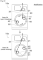
- the yarn winding machine 1 performs the waste winding at the yarn threading position.
- the yarn threading position and the waste winding position are different.
- the waste winding position in this modification is a 120° position.
- the waste winding position may be larger than 0° and smaller than 180°.
- the yarn threading position and the waste winding position are the same, if time of the waste winding is long, the yarn layer becomes large, and there is a possibility that the yarn layer and the windbreak plate 75 come into contact with each other.
- the waste winding position in this modification is far from the windbreak plate 75, contact between the yarn layer and the windbreak plate 75 can be more reliably prevented.
- the reason why the waste winding position is set to the 120° position is as follows. That is, the positioning mechanisms of the turret plate 40 for positioning at each of the winding position, the standby position, and the yarn switching position are provided, in the same way, another positioning mechanism for positioning at the yarn threading position is required. Since the waste winding position is set at 120°, the waste winding position is opposite to the yarn threading position across the point C which is the center of rotation of the turret plate 40, and there is no need to provide a new positioning mechanism.
- the operator performs a predetermined third operation on the operation panel 32 after the yarn threading operation (S7).
- the third operation is an operation for notifying the yarn winding machine 3 that the yarn threading operation is completed.
- the third operation is to operate a predetermined button on the operation panel 32, for example.
- the operation panel 32 transmits a yarn threading completion signal to the control device 50 (S8).
- the yarn threading completion signal is an electrical signal that is transmitted to the control device 50 by performing the third operation on the operation panel 32.
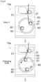
- the control device 50 controls the turret motor 53 to rotate the turret plate 40 counterclockwise, thereby setting the first bobbin holder 41 at the waste winding position (S9, from state 3A to state 3B in FIG. 10 ). As a result, the waste winding is continuously performed at the waste winding position (S10).
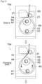
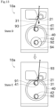
- the control device 50 controls the turret motor 53 to rotate the turret plate 40 counterclockwise, thereby setting the first bobbin holder 41 at the first switching position and the second bobbin holder 42 at the second switching position (from state A in FIG. 11 to state B in FIG. 12 ).
- the first switching position and the second switching position are positions of the bobbins 91, 92 when switching the bobbins 91, 92 for winding the yarn 93.
- the first switching position is a position of the bobbin on which winding of the yarn 93 is newly started (in other words, a bobbin on which the yarn 93 is not wound, the first bobbin 91).
- the second switching position is a position of the bobbin (second bobbin 92) of the fully wound package 94. A preferable angular range of the first switching position will be described later.
- the control device 50 switches so that the yarn 93 wound on the second bobbin 92 (package 94) is wound on the first bobbin 91 (from state C in FIG. 12 to state D in FIG. 13 ).
- the specific process is the same as the yarn switching at the time of waste winding described above.
- the fully wound package 94 of the second bobbin 92 is removed from the second bobbin holder 42, and a new second bobbin 92 (the second bobbin 92 on which the yarn 93 is not wound) is attached to the second bobbin holder 42.
- the turret plate 40 rotates only in the same direction (positive direction) from a timing when the fully wound package 94 is formed on the second bobbin 92 to a timing when the yarn 13 is newly wound on the first bobbin.
- control device 50 controls the lifting and lowering motor 63 to lower the traverse device 21 and the contact roller 31 (state E in FIG. 13 ). Thereby, the contact roller 31 contacts with the first bobbin 91, and the produce of the package 94 is started.
- the first switching position is preferably a position within ⁇ 45° with respect to 0°. If the first switching position is 45° or more alternatively 180° or less, the second switching position is 210° or more alternatively 360° or less, and the fully wound package 94 closes to a yarn path to the lower winding unit 10b. Therefore, in order to prevent interference between the fully wound package 94 and the yarn path, an offset amount of the upper winding unit 10a with respect to the lower winding unit 10b is increased, so the installation area of the yarn winding machine 1 is increased. Therefore, it is not preferable that the first switching position is 45° or more and 180° or less.
- the first switching position is 180° or more alternatively 315° or less, it becomes difficult to wind the yarn 93 connected to the fully wound package 94 on the first bobbin 91. Therefore, it is not preferable that the first switching position is 180° or more and 315° or less.
- the first switching position is preferably a position within ⁇ 45° with respect to 0°.
- the control device 50 controls the turret motor 53 and rotates the turret plate 40 to set first bobbin holder 41 at 0° position (winding position). That is, when the first switching position is larger than 315° and smaller than 360°, the control device 50 rotates the turret plate 40 counterclockwise (positive direction) after the switching.
- the control device 50 rotates the turret plate 40 clockwise (opposite direction) after the switching. After that, the upper winding unit 10a winds the yarn 93 on the first bobbin 91 to produce the package 94.
- the yarn winding machine 1 of this embodiment includes the lower winding unit 10b and the upper winding unit 10a.
- the lower winding unit 10b winds the yarn 93 fed from the yarn feed roller 100 to produce the package 94.
- the upper winding unit 10a is arranged at a higher position than the lower winding unit 10b and at an offset position perpendicular to the axial direction of the package 94 with respect to the lower winding unit 10b in the plan view, the upper winding unit 10a winds the yarn 93 fed from the yarn feed roller 100 to produce the package 94.
- the upper winding unit 10a includes the first bobbin holder 41, the second bobbin holder 42, turret plate 40, and the contact roller 31.
- the first bobbin holder 41 holds the first bobbin 91.
- the second bobbin holder 42 holds the second bobbin 92.
- the first bobbin holder 41 and the second bobbin holder 42 are attached to the turret plate 40, and the turret plate 40 changes the position of the first bobbin holder 41 and the second bobbin holder 42 by rotating around the rotation axis parallel to the axial direction of the package 94.
- the contact roller 31 rotates in contact with the first bobbin 91, the second bobbin 92, or the package 94 when producing the package 94.
- the position where the first bobbin 91, the second bobbin 92, or the package 94 contact with the contact roller 31 and the yarn is wound on the first bobbin 91 or the second bobbin 92 to produce the package 94 is defined as 0° or 360°
- the rotation direction of rotating from the 0° toward the offset direction in which the upper winding unit 10a is offset with respect to the lower winding unit 10b is defined as positive
- the turret plate 40 sets the position of the first bobbin holder 41 to the position larger than 270° and smaller than 360° by receiving the signal for threading the yarn 93 to the first bobbin 91 (yarn threading start signal).
- the offset amount in which the upper winding unit 10a is offset with respect to the lower winding unit 10b can be reduced, and the installation area of the yarn winding machine 1 can be reduced.
- the turret plate 40 receives the signal for threading the yarn 93 on the first bobbin 91 and sets the position of the first bobbin holder 41 to the position larger than 290° and smaller than 340°.
- the yarn threading of the upper winding unit 10a can be performed at a position farther from the yarn path of the lower winding unit 10b and at a position where the possibility of contact between the yarn 93 and the contact roller 31 is further reduced.
- the turret plate 40 sets the position of one of the first bobbin holder 41 and the second bobbin holder 42 to 180° and sets the other position to 0°.
- the yarn switching can be performed in a state where the first bobbin 91 and the second bobbin 92 are positioned far from the yarn path of the lower winding unit 10b.
- the turret plate 40 rotates so that the positions of the first bobbin holder 41 and the second bobbin holder 42 are changed only in the positive direction.
- Control of the turret plate 40 can be simplified.
- the offset amount can be reduced.
- the position of the first bobbin holder 41 is set to the position larger than 270° and smaller than 360°, and then by receiving the signal indicating the completion of the operation of threading the yarn 93 to the first bobbin 91 (the yarn threading completion signal), the position of the first bobbin holder 41 is set to the position greater than 0° and less than 180°.
- the upper winding unit 10a includes the windbreak plate 75 for preventing the accompanying flow generated by the rotation of the package 94 formed on the first bobbin holder 41 or the second bobbin holder 42 from affecting the yarn wound at the lower winding unit 10b.
- the yarn winding machine 1 of the present embodiment when the package 94 formed on the second bobbin 92 is fully wound, in a state where the turret plate 40 sets the position of the first bobbin holder 41 to the position of less than ⁇ 45° with respect to 0°, the yarn 93 wound on the second bobbin 92 is switched to be wound on the first bobbin 91.
- the fully wound package 94 does not pass through a range close to the yarn path to the lower winding unit 10b. Therefore, it is possible to further reduce the offset amount of the upper winding unit 10a. In addition, the operation of winding the yarn 93 connected to the package 94 on the first bobbin 91 can be easily performed.
- the traverse device 21 of the above embodiment is of cam drum type, the traverse device 21 may have a different configuration as long as it is possible to reciprocate the traverse guide 23 in the winding width direction.
- a belt-type traverse device instead of the traverse device 21, may be used.
- the process diagram in the above embodiment and the modification is an example, and some of the processes may be omitted, the contents of some of the processes may be changed, or a new process may be added.
Landscapes
- Replacing, Conveying, And Pick-Finding For Filamentary Materials (AREA)
- Winding Filamentary Materials (AREA)
Applications Claiming Priority (1)
| Application Number | Priority Date | Filing Date | Title |
|---|---|---|---|
| JP2022049589 | 2022-03-25 |
Publications (2)
| Publication Number | Publication Date |
|---|---|
| EP4249414A1 EP4249414A1 (en) | 2023-09-27 |
| EP4249414B1 true EP4249414B1 (en) | 2025-06-04 |
Family
ID=85724990
Family Applications (1)
| Application Number | Title | Priority Date | Filing Date |
|---|---|---|---|
| EP23163013.8A Active EP4249414B1 (en) | 2022-03-25 | 2023-03-21 | Yarn winding machine |
Country Status (4)
| Country | Link |
|---|---|
| EP (1) | EP4249414B1 (enExample) |
| JP (1) | JP2023143807A (enExample) |
| KR (1) | KR20230139318A (enExample) |
| CN (1) | CN116803880B (enExample) |
Family Cites Families (11)
| Publication number | Priority date | Publication date | Assignee | Title |
|---|---|---|---|---|
| EP0703179A3 (de) * | 1994-08-24 | 1996-08-21 | Rieter Ag Maschf | Automatische Spulmaschine und Verfahren zur Übergabe des Fadens von einer vollen Spule an eine leere Hülse |
| US6015113A (en) * | 1997-10-06 | 2000-01-18 | E. I. Du Pont De Nemours And Company | Winder for synthetic filaments |
| JPH11193183A (ja) * | 1997-12-29 | 1999-07-21 | Murata Mach Ltd | 弾性糸用紡糸巻取機及び弾性糸パッケージ |
| JP3440839B2 (ja) * | 1998-09-11 | 2003-08-25 | 村田機械株式会社 | 紡糸巻取機の糸掛け方法 |
| JP3303850B2 (ja) * | 1999-07-01 | 2002-07-22 | 村田機械株式会社 | 紡糸巻取機、及びそのバンチ巻方法 |
| JP2008290819A (ja) * | 2007-05-23 | 2008-12-04 | Tmt Machinery Inc | 糸条巻取機 |
| JP2012144323A (ja) * | 2011-01-11 | 2012-08-02 | Tmt Machinery Inc | 紡糸巻取装置及び紡糸巻取設備 |
| DE102012018491A1 (de) * | 2011-10-15 | 2013-04-18 | Oerlikon Textile Gmbh & Co. Kg | Aufspulmaschine und Verfahren zum Fixieren eines Fadenendes |
| JP5766576B2 (ja) * | 2011-10-19 | 2015-08-19 | Tmtマシナリー株式会社 | 紡糸巻取装置 |
| JP5995513B2 (ja) * | 2012-05-09 | 2016-09-21 | Tmtマシナリー株式会社 | 紡糸巻取装置 |
| CN104960981B (zh) * | 2015-04-14 | 2017-11-03 | 郑州中远氨纶工程技术有限公司 | 弹性纱线卷绕装置及弹性纱线切换卷绕方法 |
-
2023
- 2023-03-14 KR KR1020230033204A patent/KR20230139318A/ko active Pending
- 2023-03-17 JP JP2023042480A patent/JP2023143807A/ja active Pending
- 2023-03-21 EP EP23163013.8A patent/EP4249414B1/en active Active
- 2023-03-24 CN CN202310300715.8A patent/CN116803880B/zh active Active
Also Published As
| Publication number | Publication date |
|---|---|
| KR20230139318A (ko) | 2023-10-05 |
| CN116803880A (zh) | 2023-09-26 |
| CN116803880B (zh) | 2025-10-14 |
| JP2023143807A (ja) | 2023-10-06 |
| EP4249414A1 (en) | 2023-09-27 |
Similar Documents
| Publication | Publication Date | Title |
|---|---|---|
| CN100354192C (zh) | 旋转型纱线卷绕机 | |
| WO2004026746A1 (ja) | 綾振り装置 | |
| CN109641713B (zh) | 卷绕机的控制方法和卷绕机 | |
| KR100239741B1 (ko) | 사조의 권취기 | |
| KR100242091B1 (ko) | 터릿형 권취기 | |
| EP4249414B1 (en) | Yarn winding machine | |
| JP2004075340A (ja) | レボルビング型糸条巻取機 | |
| EP3363756B1 (en) | Yarn winder | |
| EP4424623A1 (en) | Yarn winding machine | |
| EP4245705A1 (en) | Yarn winding machine | |
| JPS6235502B2 (enExample) | ||
| JP2024122851A (ja) | 糸巻取機 | |
| JP3680589B2 (ja) | 合成繊維の巻取装置および巻取方法 | |
| JP7733594B2 (ja) | 糸巻取機 | |
| JP2024038600A (ja) | 糸巻取機 | |
| JP2007530390A (ja) | 巻取り装置 | |
| EP1008546A2 (en) | Take-up winder | |
| EP4624403A1 (en) | Yarn winding apparatus | |
| KR100314139B1 (ko) | 탄성사의 방사 권취방법 및 방사 권취기 | |
| JP2002255452A (ja) | ターレット型巻取機 | |
| JPH1036008A (ja) | ターレット式紡糸巻取機 | |
| JPH10273268A (ja) | ターレット式糸条巻取機の糸切替え方法 | |
| CN118561090A (zh) | 纱线卷取机 | |
| JP2000185872A (ja) | 糸条巻取機の制御方法 | |
| JP2016508473A (ja) | 巻取り機 |
Legal Events
| Date | Code | Title | Description |
|---|---|---|---|
| PUAI | Public reference made under article 153(3) epc to a published international application that has entered the european phase |
Free format text: ORIGINAL CODE: 0009012 |
|
| STAA | Information on the status of an ep patent application or granted ep patent |
Free format text: STATUS: THE APPLICATION HAS BEEN PUBLISHED |
|
| AK | Designated contracting states |
Kind code of ref document: A1 Designated state(s): AL AT BE BG CH CY CZ DE DK EE ES FI FR GB GR HR HU IE IS IT LI LT LU LV MC ME MK MT NL NO PL PT RO RS SE SI SK SM TR |
|
| STAA | Information on the status of an ep patent application or granted ep patent |
Free format text: STATUS: REQUEST FOR EXAMINATION WAS MADE |
|
| 17P | Request for examination filed |
Effective date: 20231020 |
|
| RBV | Designated contracting states (corrected) |
Designated state(s): AL AT BE BG CH CY CZ DE DK EE ES FI FR GB GR HR HU IE IS IT LI LT LU LV MC ME MK MT NL NO PL PT RO RS SE SI SK SM TR |
|
| GRAP | Despatch of communication of intention to grant a patent |
Free format text: ORIGINAL CODE: EPIDOSNIGR1 |
|
| STAA | Information on the status of an ep patent application or granted ep patent |
Free format text: STATUS: GRANT OF PATENT IS INTENDED |
|
| RIC1 | Information provided on ipc code assigned before grant |
Ipc: B65H 67/048 20060101ALI20241129BHEP Ipc: B65H 65/00 20060101AFI20241129BHEP |
|
| INTG | Intention to grant announced |
Effective date: 20241213 |
|
| P01 | Opt-out of the competence of the unified patent court (upc) registered |
Free format text: CASE NUMBER: APP_3095/2025 Effective date: 20250120 |
|
| GRAS | Grant fee paid |
Free format text: ORIGINAL CODE: EPIDOSNIGR3 |
|
| GRAA | (expected) grant |
Free format text: ORIGINAL CODE: 0009210 |
|
| STAA | Information on the status of an ep patent application or granted ep patent |
Free format text: STATUS: THE PATENT HAS BEEN GRANTED |
|
| AK | Designated contracting states |
Kind code of ref document: B1 Designated state(s): AL AT BE BG CH CY CZ DE DK EE ES FI FR GB GR HR HU IE IS IT LI LT LU LV MC ME MK MT NL NO PL PT RO RS SE SI SK SM TR |
|
| REG | Reference to a national code |
Ref country code: GB Ref legal event code: FG4D |
|
| REG | Reference to a national code |
Ref country code: CH Ref legal event code: EP |
|
| REG | Reference to a national code |
Ref country code: DE Ref legal event code: R096 Ref document number: 602023003765 Country of ref document: DE |
|
| REG | Reference to a national code |
Ref country code: IE Ref legal event code: FG4D |
|
| REG | Reference to a national code |
Ref country code: NL Ref legal event code: MP Effective date: 20250604 |
|
| PG25 | Lapsed in a contracting state [announced via postgrant information from national office to epo] |
Ref country code: ES Free format text: LAPSE BECAUSE OF FAILURE TO SUBMIT A TRANSLATION OF THE DESCRIPTION OR TO PAY THE FEE WITHIN THE PRESCRIBED TIME-LIMIT Effective date: 20250604 Ref country code: FI Free format text: LAPSE BECAUSE OF FAILURE TO SUBMIT A TRANSLATION OF THE DESCRIPTION OR TO PAY THE FEE WITHIN THE PRESCRIBED TIME-LIMIT Effective date: 20250604 |
|
| REG | Reference to a national code |
Ref country code: LT Ref legal event code: MG9D |
|
| PG25 | Lapsed in a contracting state [announced via postgrant information from national office to epo] |
Ref country code: GR Free format text: LAPSE BECAUSE OF FAILURE TO SUBMIT A TRANSLATION OF THE DESCRIPTION OR TO PAY THE FEE WITHIN THE PRESCRIBED TIME-LIMIT Effective date: 20250905 Ref country code: NO Free format text: LAPSE BECAUSE OF FAILURE TO SUBMIT A TRANSLATION OF THE DESCRIPTION OR TO PAY THE FEE WITHIN THE PRESCRIBED TIME-LIMIT Effective date: 20250904 |
|
| PG25 | Lapsed in a contracting state [announced via postgrant information from national office to epo] |
Ref country code: PL Free format text: LAPSE BECAUSE OF FAILURE TO SUBMIT A TRANSLATION OF THE DESCRIPTION OR TO PAY THE FEE WITHIN THE PRESCRIBED TIME-LIMIT Effective date: 20250604 |
|
| PG25 | Lapsed in a contracting state [announced via postgrant information from national office to epo] |
Ref country code: BG Free format text: LAPSE BECAUSE OF FAILURE TO SUBMIT A TRANSLATION OF THE DESCRIPTION OR TO PAY THE FEE WITHIN THE PRESCRIBED TIME-LIMIT Effective date: 20250604 |
|
| PG25 | Lapsed in a contracting state [announced via postgrant information from national office to epo] |
Ref country code: HR Free format text: LAPSE BECAUSE OF FAILURE TO SUBMIT A TRANSLATION OF THE DESCRIPTION OR TO PAY THE FEE WITHIN THE PRESCRIBED TIME-LIMIT Effective date: 20250604 |
|
| PG25 | Lapsed in a contracting state [announced via postgrant information from national office to epo] |
Ref country code: RS Free format text: LAPSE BECAUSE OF FAILURE TO SUBMIT A TRANSLATION OF THE DESCRIPTION OR TO PAY THE FEE WITHIN THE PRESCRIBED TIME-LIMIT Effective date: 20250904 |
|
| PG25 | Lapsed in a contracting state [announced via postgrant information from national office to epo] |
Ref country code: LV Free format text: LAPSE BECAUSE OF FAILURE TO SUBMIT A TRANSLATION OF THE DESCRIPTION OR TO PAY THE FEE WITHIN THE PRESCRIBED TIME-LIMIT Effective date: 20250604 |
|
| PG25 | Lapsed in a contracting state [announced via postgrant information from national office to epo] |
Ref country code: NL Free format text: LAPSE BECAUSE OF FAILURE TO SUBMIT A TRANSLATION OF THE DESCRIPTION OR TO PAY THE FEE WITHIN THE PRESCRIBED TIME-LIMIT Effective date: 20250604 |
|
| PG25 | Lapsed in a contracting state [announced via postgrant information from national office to epo] |
Ref country code: PT Free format text: LAPSE BECAUSE OF FAILURE TO SUBMIT A TRANSLATION OF THE DESCRIPTION OR TO PAY THE FEE WITHIN THE PRESCRIBED TIME-LIMIT Effective date: 20251006 |
|
| REG | Reference to a national code |
Ref country code: AT Ref legal event code: MK05 Ref document number: 1800199 Country of ref document: AT Kind code of ref document: T Effective date: 20250604 |