EP4195333A1 - Liquid lead storage battery - Google Patents
Liquid lead storage battery Download PDFInfo
- Publication number
- EP4195333A1 EP4195333A1 EP21853279.4A EP21853279A EP4195333A1 EP 4195333 A1 EP4195333 A1 EP 4195333A1 EP 21853279 A EP21853279 A EP 21853279A EP 4195333 A1 EP4195333 A1 EP 4195333A1
- Authority
- EP
- European Patent Office
- Prior art keywords
- frame bone
- bones
- vertical
- bone
- positive electrode
- Prior art date
- Legal status (The legal status is an assumption and is not a legal conclusion. Google has not performed a legal analysis and makes no representation as to the accuracy of the status listed.)
- Withdrawn
Links
Images







Classifications
-
- H—ELECTRICITY
- H01—ELECTRIC ELEMENTS
- H01M—PROCESSES OR MEANS, e.g. BATTERIES, FOR THE DIRECT CONVERSION OF CHEMICAL ENERGY INTO ELECTRICAL ENERGY
- H01M4/00—Electrodes
- H01M4/02—Electrodes composed of, or comprising, active material
- H01M4/64—Carriers or collectors
- H01M4/70—Carriers or collectors characterised by shape or form
- H01M4/72—Grids
- H01M4/73—Grids for lead-acid accumulators, e.g. frame plates
-
- H—ELECTRICITY
- H01—ELECTRIC ELEMENTS
- H01M—PROCESSES OR MEANS, e.g. BATTERIES, FOR THE DIRECT CONVERSION OF CHEMICAL ENERGY INTO ELECTRICAL ENERGY
- H01M4/00—Electrodes
- H01M4/02—Electrodes composed of, or comprising, active material
- H01M4/64—Carriers or collectors
- H01M4/70—Carriers or collectors characterised by shape or form
- H01M4/72—Grids
-
- H—ELECTRICITY
- H01—ELECTRIC ELEMENTS
- H01M—PROCESSES OR MEANS, e.g. BATTERIES, FOR THE DIRECT CONVERSION OF CHEMICAL ENERGY INTO ELECTRICAL ENERGY
- H01M10/00—Secondary cells; Manufacture thereof
- H01M10/06—Lead-acid accumulators
-
- H—ELECTRICITY
- H01—ELECTRIC ELEMENTS
- H01M—PROCESSES OR MEANS, e.g. BATTERIES, FOR THE DIRECT CONVERSION OF CHEMICAL ENERGY INTO ELECTRICAL ENERGY
- H01M10/00—Secondary cells; Manufacture thereof
- H01M10/06—Lead-acid accumulators
- H01M10/12—Construction or manufacture
-
- H—ELECTRICITY
- H01—ELECTRIC ELEMENTS
- H01M—PROCESSES OR MEANS, e.g. BATTERIES, FOR THE DIRECT CONVERSION OF CHEMICAL ENERGY INTO ELECTRICAL ENERGY
- H01M4/00—Electrodes
- H01M4/02—Electrodes composed of, or comprising, active material
- H01M4/14—Electrodes for lead-acid accumulators
-
- H—ELECTRICITY
- H01—ELECTRIC ELEMENTS
- H01M—PROCESSES OR MEANS, e.g. BATTERIES, FOR THE DIRECT CONVERSION OF CHEMICAL ENERGY INTO ELECTRICAL ENERGY
- H01M4/00—Electrodes
- H01M4/02—Electrodes composed of, or comprising, active material
- H01M4/14—Electrodes for lead-acid accumulators
- H01M4/16—Processes of manufacture
- H01M4/20—Processes of manufacture of pasted electrodes
-
- H—ELECTRICITY
- H01—ELECTRIC ELEMENTS
- H01M—PROCESSES OR MEANS, e.g. BATTERIES, FOR THE DIRECT CONVERSION OF CHEMICAL ENERGY INTO ELECTRICAL ENERGY
- H01M4/00—Electrodes
- H01M4/02—Electrodes composed of, or comprising, active material
- H01M4/64—Carriers or collectors
- H01M4/66—Selection of materials
- H01M4/68—Selection of materials for use in lead-acid accumulators
-
- H—ELECTRICITY
- H01—ELECTRIC ELEMENTS
- H01M—PROCESSES OR MEANS, e.g. BATTERIES, FOR THE DIRECT CONVERSION OF CHEMICAL ENERGY INTO ELECTRICAL ENERGY
- H01M4/00—Electrodes
- H01M4/02—Electrodes composed of, or comprising, active material
- H01M4/64—Carriers or collectors
- H01M4/66—Selection of materials
- H01M4/68—Selection of materials for use in lead-acid accumulators
- H01M4/685—Lead alloys
-
- H—ELECTRICITY
- H01—ELECTRIC ELEMENTS
- H01M—PROCESSES OR MEANS, e.g. BATTERIES, FOR THE DIRECT CONVERSION OF CHEMICAL ENERGY INTO ELECTRICAL ENERGY
- H01M4/00—Electrodes
- H01M4/02—Electrodes composed of, or comprising, active material
- H01M4/64—Carriers or collectors
- H01M4/82—Multi-step processes for manufacturing carriers for lead-acid accumulators
-
- Y—GENERAL TAGGING OF NEW TECHNOLOGICAL DEVELOPMENTS; GENERAL TAGGING OF CROSS-SECTIONAL TECHNOLOGIES SPANNING OVER SEVERAL SECTIONS OF THE IPC; TECHNICAL SUBJECTS COVERED BY FORMER USPC CROSS-REFERENCE ART COLLECTIONS [XRACs] AND DIGESTS
- Y02—TECHNOLOGIES OR APPLICATIONS FOR MITIGATION OR ADAPTATION AGAINST CLIMATE CHANGE
- Y02E—REDUCTION OF GREENHOUSE GAS [GHG] EMISSIONS, RELATED TO ENERGY GENERATION, TRANSMISSION OR DISTRIBUTION
- Y02E60/00—Enabling technologies; Technologies with a potential or indirect contribution to GHG emissions mitigation
- Y02E60/10—Energy storage using batteries
Definitions
- the present invention relates to a liquid lead storage battery.
- An electrode plate group of a general liquid lead storage battery includes a laminate composed of a plurality of positive electrode plates and negative electrode plates alternately disposed with each other, and separators disposed between the positive electrode plates and the negative electrode plates.
- the positive electrode plate includes a positive electrode current collector and a positive electrode mixture containing a positive electrode active material, and the positive electrode active material contains lead dioxide.
- the positive electrode current collector includes a rectangular grid-like substrate and a lug continuous with the grid-like substrate, and the positive electrode mixture is held in the grid-like substrate.
- the lugs of the positive electrode current collectors of the plurality of positive electrode plates are connected together by a positive electrode strap.
- the negative electrode plate includes a negative electrode current collector and a negative electrode mixture containing a negative electrode active material, and the negative electrode active material contains metallic lead.
- the negative electrode current collector includes a rectangular grid-like substrate and a lug continuous with the grid-like substrate, and the negative electrode mixture is held in the grid-like substrate.
- the lugs of the negative electrode current collectors of the plurality of negative electrode plates are connected together by a negative electrode strap.
- the positive electrode current collector and the negative electrode current collector are mainly composed of lead or a lead alloy, and openings of the grid-like substrate are filled with the positive electrode mixture or the negative electrode mixture.
- a grid-like substrate one with a structure including a frame bone forming four sides of a rectangular shape, and a plurality of intermediate bones connected to the frame bone and present inward of the frame bone.
- the frame bone includes an upper frame bone located on the upper side of the grid-like substrate and extending in the horizontal direction, a lower frame bone located on the lower side of the grid-like substrate and extending in the horizontal direction, and a pair of vertical frame bones extending in the vertical direction.
- a lug protrudes upward from a position offset from the center of the upper frame bone in its longitudinal direction to the side closer to either of the pair of vertical frame bones.
- the plurality of intermediate bones includes a plurality of vertical intermediate bones extending from the upper frame bone toward the lower frame bone side, and a plurality of horizontal intermediate bones connecting the pair of vertical frame bones. Openings to be filled with a positive electrode mixture or a negative electrode mixture are formed by only the intermediate bones or by the intermediate bones and the frame bone.
- the horizontal intermediate bones include one only extending from one of the pair of vertical frame bones toward the other side or from the other of the pair of vertical frame bones toward the one side, and not connecting the pair of vertical frame bones.
- a conventional general positive electrode grid has a simple grid shape in which all vertical intermediate bones and horizontal intermediate bones intersect orthogonally.
- a simple grid shape in a portion far from a lug of a positive electrode plate (a portion close to a corner between a vertical frame bone on the side where the lug is not present, and a lower frame bone: an opposite corner area), the path of current is longer than those in the other portions, and therefore the resistance is higher. That is, the positive electrode grid having the simple grid shape has a problem that the potential distribution in the plane is uneven. Following this, the state of use of the positive electrode grid becomes uneven in the plane, leading to the occurrence of stratification or a state where only a portion close to the lug degrades (softens), so that the life performance decreases.
- a positive electrode grid is formed in a shape in which all vertical intermediate bones extend in such a way that the distances therebetween in the left-right direction increase as away from a lug.
- the path of current from an opposite corner area to the lug becomes shorter than that in the simple grid shape so that the resistance becomes lower, and therefore the potential distribution in the plane becomes better.
- the area of an opening increases as away from the lug, when vibration or impact is applied in on-board use or the like, an active material tends to fall off so that the discharge capacity corresponding to a fallen portion is reduced, and therefore the life tends to decrease.
- PTL 2 describes, as a grid substrate of a current collector forming a liquid lead storage battery, a grid having a shape in which vertical intermediate bones on the side near a lug extend perpendicularly to an upper frame bone and a lower frame bone, and the other vertical intermediate bones are inclined so as to expand radially from an opposite corner area.
- the grid includes seven vertical intermediate bones expanding radially, and three of them are not in direct contact with the upper frame bone, but are directly connected to the vertical intermediate bone extending perpendicularly.
- one aspect of the present invention provides a liquid lead storage battery having the following configurations (1) to (3).
- a new liquid lead storage battery in which the potential distribution of a positive electrode grid is good and which can obtain stable performance even in use where extraction current is high.
- a liquid lead storage battery includes an electrode plate group 1 in which a plurality of positive electrode plates 10 and a plurality of negative electrode plates 20 are alternately stacked with ribbed separators 30 interposed therebetween.
- the electrode plate groups 1 are housed, along with a non-illustrated electrolytic solution, in cell chambers of a battery case 41 such that the stacking direction of the electrode plate groups 1 is along the horizontal direction (i.e. plate surfaces of the positive electrode plates 10 and the negative electrode plates 20 are along the vertical direction), and the electrode plate groups 1 are immersed in the electrolytic solution in the cell chambers of the battery case 41.
- the liquid lead storage battery includes the electrode plate groups 1 and the battery case 41 having the cell chambers housing the electrode plate groups 1 along with the electrolytic solution, the electrode plate groups 1 are each housed in one of the cell chambers, and the number of the positive electrode plates 10 forming the electrode plate group 1 is equal to or less than the number of the negative electrode plates 20.
- the number of the positive electrode plates 10 may be equal to the number of the negative electrode plates 20 or may be greater than the number of the negative electrode plates 20.
- the positive electrode plate 10 includes a positive electrode current collector and a positive electrode mixture containing a positive electrode active material, and the positive electrode active material contains lead dioxide.
- the positive electrode current collector includes a rectangular grid-like substrate and a lug 11 continuous with the grid-like substrate, and the positive electrode mixture is held in the grid-like substrate.
- the negative electrode plate 20 includes a negative electrode current collector and a negative electrode mixture containing a negative electrode active material, and the negative electrode active material contains metallic lead.
- the negative electrode current collector includes a rectangular grid-like substrate and a lug 21 continuous with the grid-like substrate, and the negative electrode mixture is held in the grid-like substrate.
- the positive electrode mixture or the negative electrode mixture is filled in openings of the corresponding grid-like substrate and is present as an active material layer on both plate surfaces of the grid-like substrate.
- the positive electrode current collector will be described in detail later.
- the negative electrode current collector forming the negative electrode plate 20 is formed by a continuous casting method.
- a negative electrode current collector producing method other than the continuous casting method a lead alloy casting method, a punching method for a lead alloy rolled plate, or an expanding method using a lead alloy rolled plate can be cited.
- the separator 30 is a porous film body made of resin, glass, or the like and has a flat-plate base surface and, as needed, a fold-like rib protruding in a direction perpendicular to the plane direction of the base surface.
- the lugs 11 of the plurality of positive electrode plates 10 are connected together by a positive electrode strap 13, and the lugs 21 of the plurality of negative electrode plates 20 are connected together by a negative electrode strap 23.
- the positive electrode strap 13 is connected to one end of a positive electrode terminal 15, and the negative electrode strap 23 is connected to one end of a negative electrode terminal 25.
- the other end of the positive electrode terminal 15 and the other end of the negative electrode terminal 25 pass through a lid 43 closing an opening of the battery case 41 and are exposed to the outside of a case body of the liquid lead storage battery formed by the battery case 41 and the lid 43.
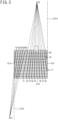
- FIG. 2 illustrates a first embodiment of a positive electrode current collector forming a positive electrode plate 10.
- a positive electrode current collector 5 of the first embodiment includes a horizontally long rectangular grid-like substrate 51 and a lug 11 continuous with the grid-like substrate, and a positive electrode mixture is held in the grid-like substrate 51.
- the grid-like substrate 51 includes a frame bone forming four sides of the rectangular shape, and a plurality of intermediate bones connected to the frame bone and present inward of the frame bone. In the rectangular shape forming the frame bone, the horizontal side is longer than the vertical side.
- the frame bone includes an upper frame bone 511 located on the upper side of the grid-like substrate and extending in the horizontal direction, a lower frame bone 512 located on the lower side of the grid-like substrate and extending in the horizontal direction, a left frame bone 513 located on the left side of the grid-like substrate and extending in the vertical direction, and a right frame bone 514 located on the right side of the grid-like substrate and extending in the vertical direction.
- the lug 11 protrudes upward from a position offset from the center of the upper frame bone 511 in its longitudinal direction to the right frame bone 514 side.
- the plurality of intermediate bones is formed by first vertical intermediate bones 61 to 65 extending from the lower frame bone 512 side toward the upper frame bone 511 side while obliquely expanding from each other, and directly reaching the upper frame bone 511, second vertical intermediate bones 71 to 80 extending from the upper frame bone 511 toward the lower frame bone 512 side while obliquely expanding from each other, a vertical intermediate bone 516 extending parallel to the left frame bone 513 and the right frame bone 514 and connecting the upper frame bone 511 and the lower frame bone 512 to each other, and 17 horizontal intermediate bones 517 connecting the left frame bone 513 and the right frame bone 514 to each other.
- the horizontal intermediate bones 517 extend parallel to the upper frame bone 511 and the lower frame bone 512.
- the cross-sectional areas of the upper frame bone 511, the left frame bone 513, and the right frame bone 514 are greater than the cross-sectional areas of the first vertical intermediate bones 61 to 65, the second vertical intermediate bones 71 to 80, the vertical intermediate bone 516, and the horizontal intermediate bones 517.
- the vertical intermediate bones extending from the lower frame bone 512 side toward the upper frame bone 511 side while obliquely expanding from each other are only the first vertical intermediate bones 61 to 65, and all of them directly reach the upper frame bone 511.
- Table 1 shows distances Ln of the first vertical intermediate bones 61 to 65, the second vertical intermediate bones 71 to 80, and the vertical intermediate bone 516 from a first reference line (a line indicating the center position of the left frame bone 513 in its width direction) S1, ratios Ln/Ls of the distances Ln to a distance (a distance between the pair of vertical frame bones) Ls between the first reference line S1 and a second reference line (a line indicating the center position of the right frame bone 514 in its width direction) S2, and angles ⁇ n formed by the first vertical intermediate bones 61 to 65, the second vertical intermediate bones 71 to 80, and the vertical intermediate bone 516, and the upper frame bone 511 on the left frame bone 513 side.
- the distance Ls is 135 mm.
- Start points of the first vertical intermediate bones 61 to 65 are all present between the center (the center line C) between the pair of vertical frame bones (the left frame bone 513 and the right frame bone 514) and the left frame bone (the first vertical frame bone being the vertical frame bone on the side where the lug is not present) 513, and are not present between the center line C and the right frame bone 514. Further, the range in which the start points of the first vertical intermediate bones 61 to 65 are present is only up to a position where the distance from the left frame bone 513 becomes 7/20 of the distance Ls between the pair of vertical frame bones (i.e., the range up to a line C1 where the distance from the first reference line S1 becomes 0.35 Ls).
- Angles ⁇ 1 to ⁇ 5 formed by the first vertical intermediate bones 61 to 65 and the upper frame bone 511 on the left frame bone 513 side are less than 90°.
- Angles ⁇ 6 to ⁇ 10 formed by the second vertical intermediate bones 71 to 76 and the upper frame bone 511 on the left frame bone 513 side are less than 90°, and angles ⁇ 12 to ⁇ 16 formed by the second vertical intermediate bones 76 to 80 and the upper frame bone 511 on the left frame bone 513 side are greater than 90°.
- An angle ⁇ 11 formed by the vertical intermediate bone 516 and the upper frame bone 511 is 90°.
- start points of the second vertical intermediate bones 71 to 80 connection points to the upper frame bone
- the range in which start points of the second vertical intermediate bones 71 to 80 (connection points to the upper frame bone) are present is only up to a position where the distance from the right frame bone 514 becomes 13/20 of the distance Ls between the pair of vertical frame bones (i.e., the range up to the line C1 where the distance from the second reference line S2 becomes 0.65 Ls).
- the first vertical intermediate bones 62 to 65 connect the upper frame bone 511 and the lower frame bone 512 to each other (the first vertical intermediate bone 62 extends from the upper frame bone 511 and reaches a corner between the lower frame bone 512 and the left frame bone 513), but the first vertical intermediate bone 61 does not reach the lower frame bone 512 and connects the upper frame bone 511 and the horizontal intermediate bones 517 to each other.
- the second vertical intermediate bones 71 to 78 connect the upper frame bone 511 and the lower frame bone 512 to each other, but the second vertical intermediate bones 79, 80 do not reach the lower frame bone 512 and connect the upper frame bone 511 and the right frame bone 514 to each other.
- the positive electrode current collector 5 of the first embodiment is formed by punching a lead alloy rolled plate.
- a positive electrode current collector producing method other than the punching method a lead alloy casting method or an expanding method using a lead alloy rolled plate can be cited.
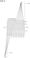
- FIG. 4 illustrates a second embodiment of a positive electrode current collector forming a positive electrode plate 10.
- the positive electrode current collector of the second embodiment is different in design from the vertical intermediate bones of the positive electrode current collector of the first embodiment, but is the same other than that.
- a plurality of intermediate bones is formed by first vertical intermediate bones 61 to 66 extending from the lower frame bone 512 side toward the upper frame bone 511 side while obliquely expanding from each other, and directly reaching the upper frame bone 511, second vertical intermediate bones 71 to 80 extending from the upper frame bone 511 toward the lower frame bone 512 side while obliquely expanding from each other, and 17 horizontal intermediate bones 517 connecting a left frame bone 513 and a right frame bone 514 to each other.
- the horizontal intermediate bones 517 extend parallel to the upper frame bone 511 and the lower frame bone 512.
- the cross-sectional areas of the upper frame bone 511, the left frame bone 513, and the right frame bone 514 are greater than the cross-sectional areas of the first vertical intermediate bones 61 to 66, the second vertical intermediate bones 71 to 80, and the horizontal intermediate bones 517.
- the vertical intermediate bones extending from the lower frame bone 512 side toward the upper frame bone 511 side while obliquely expanding from each other are only the first vertical intermediate bones 61 to 66, and all of them directly reach the upper frame bone 511.
- Table 2 shows distances Ln of the first vertical intermediate bones 61 to 66 and the second vertical intermediate bones 71 to 80 from a first reference line (a line indicating the center position of the left frame bone 513 in its width direction) S1, ratios Ln/Ls of the distances Ln to a distance (a distance between the pair of vertical frame bones) Ls between the first reference line S1 and a second reference line (a line indicating the center position of the right frame bone 514 in its width direction) S2, and angles ⁇ n formed by the first vertical intermediate bones 61 to 66 and the second vertical intermediate bones 71 to 80, and the upper frame bone 511 on the left frame bone 513 side.
- the distance Ls is 135 mm.
- Start points of the first vertical intermediate bones 61 to 66 are all present between the center (the center line C) between the pair of vertical frame bones (the left frame bone 513 and the right frame bone 514) and the left frame bone (the first vertical frame bone being the vertical frame bone on the side where a lug is not present) 513, and are not present between the center line C and the right frame bone 514. Further, the range in which the start points of the first vertical intermediate bones 61 to 66 are present is only up to a position where the distance from the left frame bone 513 becomes 9/20 of the distance Ls between the pair of vertical frame bones (i.e., the range up to a line C1 where the distance from the first reference line S1 becomes 0.45 Ls).
- Angles ⁇ 1 to ⁇ 6 formed by the first vertical intermediate bones 61 to 66 and the upper frame bone 511 on the left frame bone 513 side are less than 90°.
- Angles ⁇ 7 to ⁇ 12 formed by the second vertical intermediate bones 71 to 76 and the upper frame bone 511 on the left frame bone 513 side are less than 90°, and angles ⁇ 13 to ⁇ 16 formed by the second vertical intermediate bones 77 to 80 and the upper frame bone 511 on the left frame bone 513 side are greater than 90°.
- start points of the second vertical intermediate bones 71 to 80 connection points to the upper frame bone
- the range in which start points of the second vertical intermediate bones 71 to 80 (connection points to the upper frame bone) are present is only up to a position where the distance from the right frame bone 514 becomes 11/20 of the distance Ls between the pair of vertical frame bones (i.e., the range up to the line C1 where the distance from the second reference line S2 becomes 0.55 Ls).
- the first vertical intermediate bones 63 to 66 connect the upper frame bone 511 and the lower frame bone 512 to each other, but the first vertical intermediate bones 61, 62 do not reach the lower frame bone 512 and connect the upper frame bone 511 and the horizontal intermediate bones 517 to each other.
- the second vertical intermediate bones 71 to 78 connect the upper frame bone 511 and the lower frame bone 512 to each other, but the second vertical intermediate bones 79, 80 do not reach the lower frame bone 512 and connect the upper frame bone 511 and the horizontal intermediate bones 517 to each other.
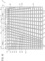
- FIG. 6 illustrates a third embodiment of a positive electrode current collector forming a positive electrode plate 10.
- the positive electrode current collector of the third embodiment is different in design from the vertical intermediate bones of the positive electrode current collector of the first embodiment, but is the same other than that.
- a plurality of intermediate bones is formed by first vertical intermediate bones 61 to 66 extending from the lower frame bone 512 side toward the upper frame bone 511 side while obliquely expanding from each other, and directly reaching the upper frame bone 511, second vertical intermediate bones 71 to 77 extending from the upper frame bone 511 toward the lower frame bone 512 side while obliquely expanding from each other, a reinforcing bone 91, and 17 horizontal intermediate bones 517 connecting a left frame bone 513 and a right frame bone 514 to each other.
- the horizontal intermediate bones 517 extend parallel to the upper frame bone 511 and the lower frame bone 512.
- the cross-sectional areas of the upper frame bone 511, the left frame bone 513, and the right frame bone 514 are greater than the cross-sectional areas of the first vertical intermediate bones 61 to 66, the second vertical intermediate bones 71 to 77, the horizontal intermediate bones 517, and the reinforcing bone 91.
- the vertical intermediate bones extending from the lower frame bone 512 side toward the upper frame bone 511 side while obliquely expanding from each other are only the first vertical intermediate bones 61 to 66, and all of them directly reach the upper frame bone 511.
- Table 3 shows distances Ln of the first vertical intermediate bones 61 to 66 and the second vertical intermediate bones 71 to 77 from a first reference line (a line indicating the center position of the left frame bone 513 in its width direction) S1, ratios Ln/Ls of the distances Ln to a distance (a distance between the pair of vertical frame bones) Ls between the first reference line S1 and a second reference line (a line indicating the center position of the right frame bone 514 in its width direction) S2, and angles ⁇ n formed by the first vertical intermediate bones 61 to 66 and the second vertical intermediate bones 71 to 77, and the upper frame bone 511 on the left frame bone 513 side.
- the distance Ls is 135 mm.
- Start points of the first vertical intermediate bones 61 to 66 are all present between the center (the center line C) between the pair of vertical frame bones (the left frame bone 513 and the right frame bone 514) and the left frame bone (the first vertical frame bone being the vertical frame bone on the side where a lug is not present) 513, and are not present between the center line C and the right frame bone 514. Further, the range in which the start points of the first vertical intermediate bones 61 to 66 are present is only up to a position where the distance from the left frame bone 513 becomes 9/20 of the distance Ls between the pair of vertical frame bones (i.e., the range up to a line C1 where the distance from the first reference line S1 becomes 0.45 Ls).
- Angles ⁇ 1 to ⁇ 6 formed by the first vertical intermediate bones 61 to 66 and the upper frame bone 511 on the left frame bone 513 side are less than 90°.
- Angles ⁇ 7 to ⁇ 13 formed by the second vertical intermediate bones 71 to 77 and the upper frame bone 511 on the left frame bone 513 side are less than 90°.
- An angle ⁇ 14 formed by the reinforcing bone 91 and the horizontal intermediate bone 517 on the left frame bone 513 side is greater than ⁇ 13 and less than 90°.
- the range in which start points of the second vertical intermediate bones 71 to 77 are present is only up to a position where the distance from the right frame bone 514 becomes 11/20 of the distance Ls between the pair of vertical frame bones (i.e., the range up to the line C1 where the distance from the second reference line S2 becomes 0.55 Ls).
- the first vertical intermediate bones 61 to 66 all connect the upper frame bone 511 and the lower frame bone 512 to each other.
- the second vertical intermediate bones 71 to 77 all connect the upper frame bone 511 and the lower frame bone 512 to each other.
- the reinforcing bone 91 connects the lower frame bone 512 and the horizontal intermediate bones 517 to each other.
- FIG. 8 illustrates a fourth embodiment of a positive electrode current collector forming a positive electrode plate 10.
- the positive electrode current collector of the fourth embodiment is different in design from the vertical intermediate bones of the positive electrode current collector of the first embodiment, but is the same other than that.
- a plurality of intermediate bones is formed by first vertical intermediate bones 61 to 66 extending from the lower frame bone 512 side toward the upper frame bone 511 side while obliquely expanding from each other, and directly reaching the upper frame bone 511, second vertical intermediate bones 71 to 77 extending from the upper frame bone 511 toward the lower frame bone 512 side while obliquely expanding from each other, a reinforcing bone 91, and 17 horizontal intermediate bones 517 connecting a left frame bone 513 and a right frame bone 514 to each other.
- the horizontal intermediate bones 517 extend parallel to the upper frame bone 511 and the lower frame bone 512.
- the cross-sectional areas of the upper frame bone 511, the left frame bone 513, and the right frame bone 514 are greater than the cross-sectional areas of the first vertical intermediate bones 61 to 66, the second vertical intermediate bones 71 to 77, the horizontal intermediate bones 517, and the reinforcing bone 91.
- the vertical intermediate bones extending from the lower frame bone 512 side toward the upper frame bone 511 side while obliquely expanding from each other are only the first vertical intermediate bones 61 to 66, and all of them directly reach the upper frame bone 511.
- Table 4 shows distances Ln of the first vertical intermediate bones 61 to 66 and the second vertical intermediate bones 71 to 77 from a first reference line (a line indicating the center position of the left frame bone 513 in its width direction) S1, ratios Ln/Ls of the distances Ln to a distance (a distance between the pair of vertical frame bones) Ls between the first reference line S1 and a second reference line (a line indicating the center position of the right frame bone 514 in its width direction) S2, and angles ⁇ n formed by the first vertical intermediate bones 61 to 66 and the second vertical intermediate bones 71 to 77, and the upper frame bone 511 on the left frame bone 513 side.
- the distance Ls is 135 mm.
- Start points of the first vertical intermediate bones 61 to 66 are all present between the center (the center line C) between the pair of vertical frame bones (the left frame bone 513 and the right frame bone 514) and the left frame bone (the first vertical frame bone being the vertical frame bone on the side where a lug is not present) 513, and are not present between the center line C and the right frame bone 514. Further, the range in which the start points of the first vertical intermediate bones 61 to 66 are present is only up to a position where the distance from the left frame bone 513 becomes 9/20 of the distance Ls between the pair of vertical frame bones (i.e., the range up to a line C1 where the distance from the first reference line S1 becomes 0.45 Ls).
- Angles ⁇ 1 to ⁇ 6 formed by the first vertical intermediate bones 61 to 66 and the upper frame bone 511 on the left frame bone 513 side are 90° or less.
- An angle ⁇ 14 formed by the reinforcing bone 91 and the horizontal intermediate bone 517 on the left frame bone 513 side is greater than ⁇ 13 and less than 90°.
- the range in which start points of the second vertical intermediate bones 71 to 77 are present is only up to a position where the distance from the right frame bone 514 becomes 11/20 of the distance Ls between the pair of vertical frame bones (i.e., the range up to the line C1 where the distance from the second reference line S2 becomes 0.55 Ls).
- the first vertical intermediate bones 61 to 66 all connect the upper frame bone 511 and the lower frame bone 512 to each other.
- the second vertical intermediate bones 71 to 77 connect the upper frame bone 511 and the lower frame bone 512 to each other.
- the reinforcing bone 91 connects the lower frame bone 512 and the horizontal intermediate bones 517 to each other.
- FIG. 10 illustrates a fifth embodiment of a positive electrode current collector forming a positive electrode plate 10.
- the positive electrode current collector of the fifth embodiment is different in design from the vertical intermediate bones of the positive electrode current collector of the first embodiment, but is the same other than that.
- a plurality of intermediate bones is formed by first vertical intermediate bones 61 to 66 extending from the lower frame bone 512 side toward the upper frame bone 511 side while obliquely expanding from each other, and directly reaching the upper frame bone 511, second vertical intermediate bones 71 to 80 extending from the upper frame bone 511 toward the lower frame bone 512 side while obliquely expanding from each other, and 17 horizontal intermediate bones 517 connecting a left frame bone 513 and a right frame bone 514 to each other.
- the horizontal intermediate bones 517 extend parallel to the upper frame bone 511 and the lower frame bone 512.
- the cross-sectional areas of the upper frame bone 511, the left frame bone 513, and the right frame bone 514 are greater than the cross-sectional areas of the first vertical intermediate bones 61 to 66, the second vertical intermediate bones 71 to 80, and the horizontal intermediate bones 517.
- the vertical intermediate bones extending from the lower frame bone 512 side toward the upper frame bone 511 side while obliquely expanding from each other are only the first vertical intermediate bones 61 to 66, and all of them directly reach the upper frame bone 511.
- Table 5 shows distances Ln of the first vertical intermediate bones 61 to 66 and the second vertical intermediate bones 71 to 80 from a first reference line (a line indicating the center position of the left frame bone 513 in its width direction) S1, ratios Ln/Ls of the distances Ln to a distance (a distance between the pair of vertical frame bones) Ls between the first reference line S1 and a second reference line (a line indicating the center position of the right frame bone 514 in its width direction) S2, and angles ⁇ n formed by the first vertical intermediate bones 61 to 66 and the second vertical intermediate bones 71 to 80, and the upper frame bone 511 on the left frame bone 513 side.
- the distance Ls is 135 mm.
- Start points of the first vertical intermediate bones 61 to 66 are all present between the center (the center line C) between the pair of vertical frame bones (the left frame bone 513 and the right frame bone 514) and the left frame bone (the first vertical frame bone being the vertical frame bone on the side where a lug is not present) 513, and are not present between the center line C and the right frame bone 514. Further, the range in which the start points of the first vertical intermediate bones 61 to 66 are present is only up to a position where the distance from the left frame bone 513 becomes 9/20 of the distance Ls between the pair of vertical frame bones (i.e., the range up to a line C1 where the distance from the first reference line S1 becomes 0.45 Ls).
- Angles ⁇ 1 to ⁇ 6 formed by the first vertical intermediate bones 61 to 66 and the upper frame bone 511 on the left frame bone 513 side are 90° or less.
- start points of the second vertical intermediate bones 71 to 80 are present is only up to a position where the distance from the right frame bone 514 becomes 11/20 of the distance Ls between the pair of vertical frame bones (i.e., the range up to the line C1 where the distance from the second reference line S2 becomes 0.55 Ls).
- the first vertical intermediate bones 61 to 66 all connect the upper frame bone 511 and the lower frame bone 512 to each other.
- the second vertical intermediate bones 71 to 78 connect the upper frame bone 511 and the lower frame bone 512 to each other, but the second vertical intermediate bones 79, 80 do not reach the lower frame bone 512 and connect the upper frame bone 511 and the horizontal intermediate bones 517 to each other.
- a plurality of intermediate bones is formed by 16 vertical intermediate bones 516 connecting an upper frame bone 511 and a lower frame bone 512 to each other, and 17 horizontal intermediate bones 517 connecting a left frame bone 513 and a right frame bone 514 to each other.
- the vertical intermediate bones 516 extend parallel to the left frame bone 513 and the right frame bone 514.
- the positive electrode current collector 50 does not include the first vertical intermediate bones extending from the lower frame bone 512 side toward the upper frame bone 511 side while obliquely expanding from each other, and directly reaching the upper frame bone 511, or the second vertical intermediate bones extending from the upper frame bone 511 toward the lower frame bone 512 side while obliquely expanding from each other.
- the horizontal intermediate bones 517 extend parallel to the upper frame bone 511 and the lower frame bone 512.
- the cross-sectional areas of the upper frame bone 511, the left frame bone 513, and the right frame bone 514 are greater than the cross-sectional areas of the vertical intermediate bones 516, the horizontal intermediate bones 517, and a reinforcing bone 91.
- Table 6 shows distances Ln of the 16 vertical intermediate bones 516 from a first reference line (a line indicating the center position of the left frame bone 513 in its width direction) S1, ratios Ln/Ls of the distances Ln to a distance (a distance between the pair of vertical frame bones) Ls between the first reference line S1 and a second reference line (a line indicating the center position of the right frame bone 514 in its width direction) S2, and angles ⁇ n (all 90°) formed by the vertical intermediate bones 516 and the upper frame bone 511 on the left frame bone 513 side.
- the distance Ls is 135 mm.
- a plurality of intermediate bones is formed by second vertical intermediate bones 71 to 85 extending from an upper frame bone 511 toward the lower frame bone 512 side while obliquely expanding from each other, a vertical intermediate bone 516 extending parallel to a left frame bone 513 and a right frame bone 514 and connecting the upper frame bone 511 and the lower frame bone 512 to each other, and 17 horizontal intermediate bones 517 connecting the left frame bone 513 and the right frame bone 514 to each other.
- the positive electrode current collector 50A does not include the first vertical intermediate bones extending from the lower frame bone 512 side toward the upper frame bone 511 side while obliquely expanding from each other, and directly reaching the upper frame bone 511.
- the horizontal intermediate bones 517 extend parallel to the upper frame bone 511 and the lower frame bone 512.
- the cross-sectional areas of the upper frame bone 511, the left frame bone 513, and the right frame bone 514 are greater than the cross-sectional areas of the vertical intermediate bone 516, the second vertical intermediate bones 71 to 85, and the horizontal intermediate bones 517.
- Table 7 shows distances Ln of the second vertical intermediate bones 71 to 85 from a first reference line (a line indicating the center position of the left frame bone 513 in its width direction) S1, ratios Ln/Ls of the distances Ln to a distance (a distance between the pair of vertical frame bones) Ls between the first reference line S1 and a second reference line (a line indicating the center position of the right frame bone 514 in its width direction) S2, and angles ⁇ n formed by the second vertical intermediate bones 71 to 85 and the upper frame bone 511 on the left frame bone 513 side.
- the distance Ls is 135 mm.
- Start points of the second vertical intermediate bones 71 to 86 are also present outward of a position where the distance from the right frame bone 514 becomes 11/20 of the distance Ls between the pair of vertical frame bones (i.e., a line C1 where the distance from the second reference line S2 becomes 0.55 Ls) .
- Angles ⁇ 1 to ⁇ 11, ⁇ 13 to ⁇ 16 formed by the second vertical intermediate bones 71 to 85 and the upper frame bone 511 on the left frame bone 513 side are less than 90°.
- the second vertical intermediate bones 74 to 84 connect the upper frame bone 511 and the lower frame bone 512 to each other, the second vertical intermediate bones 71 to 73 connect the upper frame bone 511 and the left frame bone 513 to each other, and the second vertical intermediate bone 85 connects the upper frame bone 511 and the right frame bone 514 to each other.
- Lines extending the second vertical intermediate bones 71 to 85 and the vertical intermediate bone 516 upward above the upper frame bone 511 converge to a single point on the extension line of the vertical intermediate bone 516. That is, this convergence point is located between an extension line of the left frame bone 513 and an extension line of the right frame bone 514 (right above a lug 11).
- a plurality of intermediate bones is formed by first vertical intermediate bones 61 to 64 extending from the lower frame bone 512 side toward the upper frame bone 511 side while obliquely expanding from each other, and directly reaching the upper frame bone 511, 9 vertical intermediate bones 516 extending parallel to a left frame bone 513 and a right frame bone 514 and connecting the upper frame bone 511 and the lower frame bone 512 to each other, reinforcing bones 92 to 94 extending from the lower frame bone 512 side toward the upper frame bone 511 side while obliquely expanding from each other, and reaching the vertical intermediate bone 516A closest to the left frame bone 513, and 17 horizontal intermediate bones 517 connecting the left frame bone 513 and the right frame bone 514 to each other.
- the horizontal intermediate bones 517 extend parallel to the upper frame bone 511 and the lower frame bone 512.
- the positive electrode current collector 50B does not include the second vertical intermediate bones extending from the upper frame bone 511 toward the lower frame bone 512 side while obliquely expanding from each other.
- the reinforcing bones 92 to 94 not directly reaching the upper frame bone 511 and reaching the vertical intermediate bone 516A, in addition to the first vertical intermediate bones 61 to 64 directly reaching the upper frame bone 511.
- the cross-sectional areas of the upper frame bone 511, the left frame bone 513, and the right frame bone 514 are greater than the cross-sectional areas of the 9 vertical intermediate bones 516, the first vertical intermediate bones 61 to 64, the reinforcing bones 92 to 94, and the horizontal intermediate bones 517.
- Table 8 shows distances Ln of the first vertical intermediate bones 61 to 64 and the vertical intermediate bones 516 from a first reference line (a line indicating the center position of the left frame bone 513 in its width direction) S1, ratios Ln/Ls of the distances Ln to a distance (a distance between the pair of vertical frame bones) Ls between the first reference line S1 and a second reference line (a line indicating the center position of the right frame bone 514 in its width direction) S2, and angles ⁇ n formed by the first vertical intermediate bones 61 to 64 and the vertical intermediate bones 516, and the upper frame bone 511 on the left frame bone 513 side (the angles formed by the vertical intermediate bones 516 and the upper frame bone 511 are all 90°).
- the distance Ls is 135 mm.
- Start points of the first vertical intermediate bones 61 to 64 are all present between the center (the center line C) between the pair of vertical frame bones (the left frame bone 513 and the right frame bone 514) and the left frame bone (the first vertical frame bone being the vertical frame bone on the side where a lug is not present) 513, and are not present between the center line C and the right frame bone 514. Further, the range in which the start points of the first vertical intermediate bones 61 to 64 are present is only up to a position where the distance from the left frame bone 513 becomes 9/20 of the distance Ls between the pair of vertical frame bones (i.e., the range up to a line C1 where the distance from the first reference line S1 becomes 0.45 Ls).
- Angles ⁇ 1 to ⁇ 4 formed by the first vertical intermediate bones 61 to 64 and the upper frame bone 511 on the left frame bone 513 side are less than 90°.
- Angles ⁇ 92 to ⁇ 94 formed by the reinforcing bones 92 to 94 and the horizontal intermediate bones 517 on the left frame bone 513 side are less than 90° and smaller than ⁇ 4.
- the positive electrode current collectors of the first to fifth embodiments satisfy all of the following (a) to (d) .
- the positive electrode current collector of Comparative Example 1 does not satisfy any of the above (a) to (d) .
- the positive electrode current collector of Comparative Example 2 does not satisfy any of the above (a) to (d) .
- Comparative Example 2 is the liquid lead storage battery described in PTL 1, and the positive electrode grid is formed in a shape in which all the vertical intermediate bones extend in such a way that the distances therebetween in the left-right direction increase as away from the lug.
- the positive electrode current collector of Comparative Example 3 does not satisfy the above (b).
- the positive electrode current collector of Comparative Example 3 is the grid described in PTL 2. In the liquid lead storage battery with this grid, when extracting a large current for use in the engine start or the like, as described above, a large current is concentrated on the vertical intermediate bone 516A so that corrosion progresses, and therefore, there is a possibility that the performance of the battery decreases rapidly.
- the positive electrode current collectors of the first to fifth embodiments satisfy all of the above (a) to (d), and therefore the potential distributions of the positive electrode grids become good so that the stable performance can be obtained even in use where extraction current is high.
- the angles formed by the first vertical intermediate bones and the upper frame bone on the first vertical frame bone side are preferably 45° or more and less than 90° and more preferably 70° or more and less than 90°.
- the range in which the start points of the first vertical intermediate bones are present is only up to the position where the distance from the left frame bone 513 becomes 9/20 of the distance Ls between the pair of vertical frame bones (i.e., satisfying the above (d)), and the range in which the start points of the second vertical intermediate bones (the connection points to the upper frame bone) are present is only up to the position where the distance from the right frame bone 514 becomes 11/20 of the distance Ls between the pair of vertical frame bones.
- the openings formed by the vertical intermediate bones, the frame bone, and the horizontal intermediate bones, that are created on the sides where the first vertical intermediate bones and the second vertical intermediate bones expand have appropriate sizes in the usual placement density, and therefore the inconvenience following the installation of a reinforcing bone, or the like does not occur.
- these openings are made larger, it is necessary to provide a reinforcing bone, and therefore a mold in the manufacture is complicated, leading to an increase in the weight of the positive electrode current collector.
- the start points of the first vertical intermediate bones are preferably present in the range from a position where the distance from the left frame bone 513 becomes 1/5 or more of the distance Ls between the pair of vertical frame bones, to a position where the distance from the left frame bone 513 becomes 1/2 or less of the distance Ls the pair of vertical frame bones.
- the lines have the convergence points P1, P2, i.e., the lines extending the first vertical intermediate bones downward below the lower frame bone 512 converge to the single point, and the lines extending the second vertical intermediate bones upward above the upper frame bone 511 converge to the single point. Therefore, the potential distribution becomes better than the case where no convergence occurs. Further, since design change is easy, it is also possible to easily cope with the development of products in many types.
- the growth in the horizontal direction tends to increase in the grid-like substrate of the positive electrode current collector.
- the left and right frame bones of the expanding positive electrode plate stretch and tear off the contacting separators.
- the separators are not torn off, there are cases where part of the positive electrode grid broken by corrosion break through the separators.
- the positive electrode and the negative electrode stacked with each other via the separator therebetween contact each other to cause a short-circuit, resulting in reaching the life early.
- the grid-like substrates of the positive electrode current collectors have the horizontally long shape, but, by satisfying all of the above (a) to (d), it is possible to obtain the significant potential distribution improvement effect and thus to prevent reaching the early life.
- the number of the first vertical intermediate bones directly connected to the upper frame bone is greater in the positive electrode current collectors 5 of the first to fourth embodiments than in the positive electrode current collector 50B of Comparative Example 3, and therefore the amount of current collected toward the upper frame bone with the large cross-sectional area is made greater so that corrosion is unlikely to occur in the vertical intermediate bones.
- the first vertical intermediate bone 61 forming the positive electrode current collector of the first embodiment and the first vertical intermediate bones 61, 62 forming the positive electrode current collectors of the second embodiment and the third embodiment do not reach the lower frame bone 512. However, it is preferable that the first vertical intermediate bones all reach the lower frame bone 512, or that even when not reaching the lower frame bone 512, all of them reach positions 0.90 times or more the distance between the upper frame bone 511 and the lower frame bone 512. Consequently, the effect to improve the potential distribution in the entire plane of the positive electrode current collector is enhanced.
- the range in which the start points of the first vertical intermediate bones are present is only up to the position where the distance from the left frame bone 513 becomes 7/20 of the distance Ls between the pair of vertical frame bones in the first embodiment, which is narrower than that in the second embodiment, and the range in which the start points of the second vertical intermediate bones are present is only up to the position where the distance from the right frame bone 514 becomes 13/20 of the distance Ls between the pair of vertical frame bones in the first embodiment, which is wider than that in the second embodiment.
- the openings formed by the vertical intermediate bones, the frame bone, and the horizontal intermediate bones, that are created on the sides where the first vertical intermediate bones and the second vertical intermediate bones expand have more appropriate sizes in the first embodiment than in the second embodiment, and therefore the first embodiment has a further advantage in that the inconvenience following the installation of a reinforcing bone, or the like does not occur.
- the positive electrode current collector of the third embodiment since the average opening area of the openings formed by the first vertical intermediate bones is smaller than those in the other embodiments, the positive electrode mixture held in the openings is likely to be prevented from peeling off or falling off, but, in comparison with the first embodiment and the second embodiment, the average opening area of the openings near the lug is made large, and therefore the third embodiment is slightly inferior to the first embodiment and the second embodiment in the current collection characteristics and the cycle life characteristics.
- the fourth embodiment since variation in the opening area of the openings is made small compared to the first to third embodiments, local peeling-off or falling-off of the positive electrode mixture is likely to be prevented, but the fourth embodiment is slightly inferior to the first to third embodiments in the cycle life characteristics for stop-start vehicles.
- the second vertical intermediate bones converge toward above the lug, and therefore the current collection characteristics and the cycle life characteristics better than those of the third embodiment and the fourth embodiment can be obtained.
- the average opening area of the openings formed by the first vertical intermediate bones is smaller than those in the other embodiments, and therefore the positive electrode mixture held in the openings is likely to be prevented from peeling off or falling off.
- the cross-sectional area of the upper frame bone 511 is preferably 235% to 300% of the average cross-sectional area of the horizontal intermediate bones 517, and the opening area in plan view of each of the plurality of openings contacting the upper frame bone 511 is preferably 50% to 75% of the average opening area of all the openings of the grid-like substrate 51.
- the average diameter of pores in the positive electrode mixture is preferably 0.15 um or more and 0.40 um or less, and the porosity of the positive electrode mixture is preferably 30% or more and 50% or less.
- a method for measuring the average diameter of pores in the positive electrode mixture is not particularly limited, and, for example, it can be measured by a mercury intrusion method.
- the porosity of the positive electrode mixture When the porosity of the positive electrode mixture is less than 30%, there is a possibility that sulfuric acid is hard to permeate into the mixture to cause a decrease in the utilization rate of the active material. On the other hand, when the porosity of the positive electrode mixture is greater than 50%, there is a possibility that the density of the mixture decreases to cause a decrease in cycle life.
- the cross-sectional areas of the second vertical intermediate bones 74 to 76 and the vertical intermediate bone 516 connected to a lower portion of the lug 11 are preferably 1.26 times or more and 1.50 times or less the cross-sectional area of all the vertical intermediate bones.
- Liquid lead storage batteries with a battery size of Q-85 were produced by the following method.
- the liquid lead storage batteries of sample No. 1 to No. 25 differ from each other in configurations of an upper frame bone of a positive electrode current collector and openings contacting the upper frame bone, but are the same other than that.
- the liquid lead storage batteries of sample No. 1 to No. 25 are configured such that, in the positive electrode current collector 5, the width (the horizontal dimension) of the grid-like substrate 51 is 135 mm, and the height (the vertical dimension) thereof is 114.5 mm. These dimensions are each a distance between the center lines of the frame bones.
- the cross-sectional areas of the left frame bone 513, the right frame bone 514, and the lower frame bone 512 are each 1.80 mm 2 .
- current collectors (a grid-like substrate and a lug for each) for positive electrode plates and negative electrode plates were produced by a punching method from a rolled plate made of a Pb-Ca-Sn alloy. In a cross section of the current collector taken along its thickness direction, rolled texture with an average interlayer distance of 20 um was observed.
- the weight of each of the positive electrode current collectors is 40.0 g.
- the vertical widths of the intermediate bones were changed simultaneously so as to make the weights of the positive electrode current collectors equal to each other among all the samples.
- the positive electrode current collectors of the liquid lead storage batteries of sample No. 1 to No. 5 are configured such that the vertical widths of all the horizontal intermediate bones 517 are equal to each other in the positive electrode current collector 5 of FIG. 2 .
- the average cross-sectional areas of all the horizontal intermediate bones 517 are 1.00 mm 2
- the average cross-sectional areas of the upper frame bones 511 are 2.00 mm 2 .
- the opening areas in plan view of the openings contacting the upper frame bones 511 are respectively 45%, 50%, 65%, 75%, and 80% of the average opening areas of all the openings in plan view.
- the average opening area of the openings contacting the upper frame bone 511 was adjusted by changing the separation distances between the horizontal intermediate bones 517. In this event, the separation distances between the horizontal intermediate bones 517 were adjusted to be equal to each other.
- the cross-sectional area of the upper frame bone 511 forming the grid-like substrate 51 is 2.23 mm 2
- the cross-sectional areas of all the horizontal intermediate bones 517 are 0.95 mm 2 . That is, the vertical width ratio of the upper frame bone 511 to the horizontal intermediate bone 517 is 235%.
- the average opening areas in plan view of the openings contacting the upper frame bones 511 are respectively 45%, 50%, 65%, 75%, and 80% of the average opening areas of all the openings in plan view.
- the average opening area of the openings contacting the upper frame bone 511 was adjusted by changing the separation distances between the horizontal intermediate bones 517. In this event, the separation distances between the horizontal intermediate bones 517 were adjusted to be equal to each other.
- the cross-sectional area of the upper frame bone 511 forming the grid-like substrate 51 is 2.43 mm 2
- the cross-sectional areas of all the horizontal intermediate bones 517 are 0.90 mm 2 . That is, the vertical width ratio of the upper frame bone 511 to the horizontal intermediate bone 517 is 270%.
- the average opening areas in plan view of the openings contacting the upper frame bones 511 are respectively 45%, 50%, 65%, 75%, and 80% of the average opening areas of all the openings in plan view.
- the average opening area of the openings contacting the upper frame bone 511 was adjusted by changing the separation distances between the horizontal intermediate bones 517. In this event, the separation distances between the horizontal intermediate bones 517 were adjusted to be equal to each other.
- the cross-sectional area of the upper frame bone 511 forming the grid-like substrate 51 is 2.55 mm 2
- the cross-sectional areas of all the horizontal intermediate bones 517 are 0.85 mm 2 . That is, the vertical width ratio of the upper frame bone 511 to the horizontal intermediate bone 517 is 300%.
- the average opening areas in plan view of the openings contacting the upper frame bones 511 are respectively 45%, 50%, 65%, 75%, and 80% of the average opening areas of all the openings in plan view.
- the average opening area of the openings contacting the upper frame bone 511 was adjusted by changing the separation distances between the horizontal intermediate bones 517. In this event, the separation distances between the horizontal intermediate bones 517 were adjusted to be equal to each other.
- the cross-sectional area of the upper frame bone 511 forming the grid-like substrate 51 is 2.56 mm 2
- the cross-sectional areas of all the horizontal intermediate bones 517 are 0.80 mm 2 . That is, the vertical width ratio of the upper frame bone 511 to the horizontal intermediate bone 517 is 320%.
- the average opening areas in plan view of the openings contacting the upper frame bones 511 are respectively 45%, 50%, 65%, 75%, and 80% of the average opening areas of all the openings in plan view.
- the average opening area of the openings contacting the upper frame bone 511 was adjusted by changing the separation distances between the horizontal intermediate bones 517. In this event, the separation distances between the horizontal intermediate bones 517 were adjusted to be equal to each other.
- the configuration of the plurality of intermediate bones forming the grid-like substrate 51 is the same as that in the positive electrode current collector 5 of the first embodiment illustrated in FIG. 2 .
- negative electrode current collectors of sample No. 1 to No. 25 ones having the same shapes and the same cross-sectional areas as those of the positive electrode current collector 5 of sample No. 1 were used.
- lead powder mainly composed of lead monoxide was kneaded with water and dilute sulfuric acid and further kneaded as needed by adding additives, thereby producing a paste for positive electrode mixture.
- the ratio ⁇ /( ⁇ + ⁇ ) between a mass ⁇ of ⁇ -lead dioxide and a mass ⁇ of ⁇ -lead dioxide contained in a positive electrode active material after formation was set to 20%.
- lead powder mainly composed of lead monoxide was kneaded with water and dilute sulfuric acid and further kneaded as needed by adding additives, thereby producing a paste for negative electrode mixture.
- the density of the positive electrode mixture included in the positive electrode plates was 4.2 g/cm3, and the density of the negative electrode mixture included in the negative electrode plates was 4.0 g/cm 3 .
- the average pore diameter of the positive electrode mixture was 0.20 um, and the porosity thereof was 40%.
- a separator there was prepared a ribbed separator made of a porous synthetic resin and having a flat-plate base surface and a fold-like rib protruding in a direction perpendicular to the plane direction of the base surface.
- the total thickness of the ribbed separator was set to 0.90 mm, the height of the rib was set to 0.65 mm, and the thickness of the base surface was set to 0.25 mm.
- the pluralities of produced positive electrode plates and negative electrode plates before formation were alternately stacked with the ribbed separators interposed therebetween, thereby producing an electrode plate group.
- the number of the positive electrode plates was set to seven, and the number of the negative electrode plates was set to eight.
- the electrode plate group was housed in a battery case.
- the lugs of the positive electrode current collectors of the positive electrode plates were joined together by a positive electrode strap, and the lugs of the negative electrode current collectors of the negative electrode plates were joined together by a negative electrode strap.
- the positive electrode strap was connected to one end of a positive electrode terminal, and the negative electrode strap was connected to one end of a negative electrode terminal.
- the battery case included a plurality of cell chambers each housing the electrode plate group, and the volume of each cell chamber was 570 cm 3 at its portion not higher than an upper level (highest liquid level line). A predetermined group pressure was applied to the electrode plate groups.
- an opening of the battery case was closed with a lid.
- a positive electrode pole and a negative electrode pole were made to respectively pass through bushings insert-molded to the lid, and welding was performed in a state where the other end of the positive electrode pole and the other end of the negative electrode pole were exposed to the outside of the liquid lead storage battery, thereby producing the positive electrode terminal and the negative electrode terminal.
- An electrolytic solution composed of dilute sulfuric acid with a specific gravity of 1.23 and containing aluminum sulfate in a concentration of 0.1 mol/L was injected to the upper level of the battery case through a liquid injection port formed in the lid, then the liquid injection port was sealed with a plug, and then battery case formation was performed, thereby obtaining the liquid lead storage battery.
- the time from the injection of the electrolytic solution until the start of energization for the formation (i.e., the soaking time) was set to 30 minutes, the amount of electricity for the formation was set to 230%, and the temperature of the electrolytic solution in the formation was set to 45°C. In this event, the amount of the injected electrolytic solution was 375cm 3 for each cell chamber.
- the specific gravity of the electrolytic solution after the formation was 1.28.
- Conditions of the life test were as follows. First, in a 75°C environment, 300A discharge for 2 seconds, CCCV charge (14.5 V, maximum charging current 50 A) for 60 minutes, 25A discharge for 5 minutes, and CCCV charge (14.5 V, maximum charging current 50 A) for 30 minutes were performed in this order as one cycle, and the plurality of cycles was repeated, and when the voltage in each discharge was reduced to 7.2 V, it was determined that the life was reached, and the number of cycles performed up to then was determined as a life.
- the growth rate R Y of the positive electrode grid in the vertical direction was confirmed when the life test reached 300 cycles.
- the growth rate R Y of the positive electrode grid was calculated as follows.
- a distance Y 1 from the top surface of the lid to the upper frame bone was measured in advance. This measurement may be performed via the liquid injection port formed in the lid, or a communication port may be formed in a proper position and the measurement may be performed via the communication port.
- the test was temporarily stopped when the life test reached 300 cycles, and a distance Y 2 from the top surface of the lid to the upper frame bone was measured.
- Liquid lead storage batteries with a battery size of Q-85 (sample No. 26 to No. 49) were produced by the following method.
- the liquid lead storage batteries of sample No. 26 to No. 49 differ from each other in configurations of the pore diameter ( ⁇ m) and the porosity (%) of the positive electrode mixture, but are the same as sample No. 8 other than that.
- the liquid lead storage batteries of sample No. 26 to No. 49 are configured such that, in the positive electrode current collector 5, the width (the horizontal dimension) of the grid-like substrate 51 is 135 mm, and the height (the vertical dimension) thereof is 114.5 mm. These dimensions are each a distance between the center lines of the frame bones.
- the cross-sectional areas of the left frame bone 513, the right frame bone 514, and the lower frame bone 512 are each 1.80 mm 2 .
- current collectors (a grid-like substrate and a lug for each) for positive electrode plates and negative electrode plates were produced by a punching method from a rolled plate made of a Pb-Ca-Sn alloy. In a cross section of the current collector taken along its thickness direction, rolled texture with an average interlayer distance of 20 um was observed.
- the weight of each of the positive electrode current collectors is 40.0 g.
- the vertical widths of the intermediate bones were changed simultaneously so as to make the weights of the positive electrode current collectors equal to each other among all the samples.
- the configurations of the grid-like substrates 51 are the same as sample No. 8, the pore diameters of positive electrode mixtures held in the grid-like substrates 51 are all 0.10 um, and the porosities thereof are respectively 20%, 30%, 40%, 50%, and 60%.
- the configurations of the grid-like substrates 51 are the same as sample No. 8, the pore diameters of positive electrode mixtures held in the grid-like substrates 51 are all 0.15 um, and the porosities thereof are respectively 20%, 30%, 40%, 50%, and 60%.
- the configurations of the grid-like substrates 51 are the same as sample No. 8, the pore diameters of positive electrode mixtures held in the grid-like substrates 51 are all 0.20 um, and the porosities thereof are respectively 20%, 30%, 40%, 50%, and 60%. Further, in the positive electrode current collector 5 included in the liquid lead storage battery of sample No. 8, the pore diameter is 0.15 ⁇ m, and the porosity is 40%.
- the configurations of the grid-like substrates 51 are the same as sample No. 8, the pore diameters of positive electrode mixtures held in the grid-like substrates 51 are all 0.40 um, and the porosities thereof are respectively 20%, 30%, 40%, 50%, and 60%.
- the configurations of the grid-like substrates 51 are the same as sample No. 8, the pore diameters of positive electrode mixtures held in the grid-like substrates 51 are all 0.45 um, and the porosities thereof are respectively 20%, 30%, 40%, 50%, and 60%.
- negative electrode current collectors of sample No. 26 to No. 49 ones having the same shapes and the same cross-sectional areas as those of the positive electrode current collector 5 of sample No. 8 were used.
- lead powder mainly composed of lead monoxide was kneaded with water and dilute sulfuric acid and further kneaded as needed by adding additives, thereby producing a paste for positive electrode mixture.
- the ratio ⁇ /( ⁇ + ⁇ ) between a mass ⁇ of ⁇ -lead dioxide and a mass ⁇ of ⁇ -lead dioxide contained in a positive electrode active material after formation was set to 20%.
- lead powder mainly composed of lead monoxide was kneaded with water and dilute sulfuric acid and further kneaded as needed by adding additives, thereby producing a paste for negative electrode mixture.
- the density of the positive electrode mixture included in the positive electrode plates was 4.2 g/cm3, and the density of the negative electrode mixture included in the negative electrode plates was 4.0 g/cm 3 .
- a separator there was prepared a ribbed separator made of a porous synthetic resin and having a flat-plate base surface and a fold-like rib protruding in a direction perpendicular to the plane direction of the base surface.
- the total thickness of the ribbed separator was set to 0.90 mm, the height of the rib was set to 0.65 mm, and the thickness of the base surface was set to 0.25 mm.
- the pluralities of produced positive electrode plates and negative electrode plates before formation were alternately stacked with the ribbed separators interposed therebetween, thereby producing an electrode plate group.
- the number of the positive electrode plates was set to seven, and the number of the negative electrode plates was set to eight.
- the electrode plate group was housed in a battery case.
- the lugs of the positive electrode current collectors of the positive electrode plates were joined together by a positive electrode strap, and the lugs of the negative electrode current collectors of the negative electrode plates were joined together by a negative electrode strap.
- the positive electrode strap was connected to one end of a positive electrode terminal, and the negative electrode strap was connected to one end of a negative electrode terminal.
- the battery case included a plurality of cell chambers each housing the electrode plate group, and the volume of each cell chamber was 570 cm 3 at its portion not higher than an upper level (highest liquid level line). A predetermined group pressure was applied to the electrode plate groups.
- an opening of the battery case was closed with a lid.
- a positive electrode pole and a negative electrode pole were made to respectively pass through bushings insert-molded to the lid, and welding was performed in a state where the other end of the positive electrode pole and the other end of the negative electrode pole were exposed to the outside of the liquid lead storage battery, thereby producing the positive electrode terminal and the negative electrode terminal.
- An electrolytic solution composed of dilute sulfuric acid with a specific gravity of 1.23 and containing aluminum sulfate in a concentration of 0.1 mol/L was injected to the upper level of the battery case through a liquid injection port formed in the lid, then the liquid injection port was sealed with a plug, and then battery case formation was performed, thereby obtaining the liquid lead storage battery.
- the time from the injection of the electrolytic solution until the start of energization for the formation (i.e., the soaking time) was set to 30 minutes, the amount of electricity for the formation was set to 230%, and the temperature of the electrolytic solution in the formation was set to 45°C. In this event, the amount of the injected electrolytic solution was 375cm 3 for each cell chamber.
- the specific gravity of the electrolytic solution after the formation was 1.28.
- Conditions of the life test were as follows. First, in a 75°C environment, 300A discharge for 2 seconds, CCCV charge (14.5 V, maximum charging current 50 A) for 60 minutes, 25A discharge for 5 minutes, and CCCV charge (14.5 V, maximum charging current 50 A) for 30 minutes were performed in this order as one cycle, and the plurality of cycles was repeated, and when the voltage in each discharge was reduced to 7.2 V, it was determined that the life was reached, and the number of cycles performed up to then was determined as a life.
- the utilization rate of the active material was obtained by measuring the discharge capacity after performing a 5-hour rate discharge test.
- the measured value of the discharge capacity was equal to or more than 32 Ah being the rated capacity of the liquid lead storage battery of Q-85 size, " ⁇ " was given by determining that the utilization rate was significantly excellent.
- the measured value of the discharge capacity was 30 Ah or more and less than 32 Ah, "O” was given by determining that the utilization rate was sufficiently excellent, but could not be said to be significantly excellent.
- Liquid lead storage batteries with a battery size of Q-85 were produced by the following method.
- the liquid lead storage batteries of sample No. 50 to No. 56 differ from each other in that, among vertical intermediate bones of positive electrode current collectors, the cross-sectional areas of the vertical intermediate bones having connection points to lower portions of lugs differ from each other, but are the same as sample No. 8 other than that.
- the liquid lead storage batteries of sample No. 50 to No. 56 are configured such that, in the positive electrode current collector 5, the width (the horizontal dimension) of the grid-like substrate 51 is 135 mm, and the height (the vertical dimension) thereof is 114.5 mm.
- the cross-sectional areas of the left frame bone 513, the right frame bone 514, and the lower frame bone 512 are each 1.80 mm 2 .
- the cross-sectional area of the upper frame bone 511 forming the grid-like substrate 51 is 2.23 mm 2
- the cross-sectional areas of all the horizontal intermediate bones 517 are 0.95 mm 2 . That is, the vertical width ratio of the upper frame bone 511 to the horizontal intermediate bone 517 is 235%.
- the average opening area in plan view of the openings contacting the upper frame bone 511 is 65%.
- current collectors (a grid-like substrate and a lug for each) for positive electrode plates and negative electrode plates were produced by a punching method from a rolled plate made of a Pb-Ca-Sn alloy. In a cross section of the current collector taken along its thickness direction, rolled texture with an average interlayer distance of 20 um was observed.
- the weight of each of the positive electrode current collectors is 40.0 g.
- the vertical widths of the intermediate bones were changed simultaneously so as to make the weights of the positive electrode current collectors equal to each other among all the samples.
- the range in which the start points of the second vertical intermediate bones 74 to 76 (the connection points to the upper frame bone) are present is between positions where the distance from the first reference line S1 becomes 80 and 105 (i.e., the range located under the lug).
- the first vertical intermediate bones 63 to 66 connect the upper frame bone 511 and the lower frame bone 512 to each other, but the first vertical intermediate bones 61, 62 do not reach the lower frame bone 512 and connect the upper frame bone 511 and the horizontal intermediate bones 517 to each other.
- the second vertical intermediate bones 71 to 78 connect the upper frame bone 511 and the lower frame bone 512 to each other, but the second vertical intermediate bones 79, 80 do not reach the lower frame bone 512 and connect the upper frame bone 511 and the horizontal intermediate bones 517 to each other.
- lines extending the first vertical intermediate bones 61 to 66 downward below the lower frame bone 512 converge to a single point.
- This convergence point P1 is located outward of an extension line L513 of the left frame bone 513. Lines extending the second vertical intermediate bones 71 to 80 upward above the upper frame bone 511 converge to a single point. This convergence point P2 is located inward of an extension line L514 of the right frame bone 514.
- the cross-sectional areas of the second vertical intermediate bones 74 to 76 and the vertical intermediate bone 516 connected to the lower portion of the lug 11 are 1.20 times the average cross-sectional area of all the vertical intermediate bones.
- the cross-sectional areas of the second vertical intermediate bones 74 to 76 and the vertical intermediate bone 516 connected to the lower portion of the lug 11 are 1.26 times the average cross-sectional area of all the vertical intermediate bones.
- the cross-sectional areas of the second vertical intermediate bones 74 to 76 and the vertical intermediate bone 516 connected to the lower portion of the lug 11 are 1.30 times the average cross-sectional area of all the vertical intermediate bones.
- the cross-sectional areas of the second vertical intermediate bones 74 to 76 and the vertical intermediate bone 516 connected to the lower portion of the lug 11 are 1.35 times the average cross-sectional area of all the vertical intermediate bones.
- the cross-sectional areas of the second vertical intermediate bones 74 to 76 and the vertical intermediate bone 516 connected to the lower portion of the lug 11 are 1.40 times the average cross-sectional area of all the vertical intermediate bones.
- the cross-sectional areas of the second vertical intermediate bones 74 to 76 and the vertical intermediate bone 516 connected to the lower portion of the lug 11 are 1.50 times the average cross-sectional area of all the vertical intermediate bones.
- the cross-sectional areas of the second vertical intermediate bones 74 to 76 and the vertical intermediate bone 516 connected to the lower portion of the lug 11 are 1.60 times the average cross-sectional area of all the vertical intermediate bones.
- negative electrode current collectors of sample No. 50 to No. 56 ones having the same shapes and the same cross-sectional areas as those of the positive electrode current collector 5 of sample No. 8 were used.
- lead powder mainly composed of lead monoxide was kneaded with water and dilute sulfuric acid and further kneaded as needed by adding additives, thereby producing a paste for positive electrode mixture.
- the ratio ⁇ /( ⁇ + ⁇ ) between a mass ⁇ of ⁇ -lead dioxide and a mass ⁇ of ⁇ -lead dioxide contained in a positive electrode active material after formation was set to 20%.
- lead powder mainly composed of lead monoxide was kneaded with water and dilute sulfuric acid and further kneaded as needed by adding additives, thereby producing a paste for negative electrode mixture.
- the density of the positive electrode mixture included in the positive electrode plates was 4.2 g/cm3, and the density of the negative electrode mixture included in the negative electrode plates was 4.0 g/cm 3 .
- a separator there was prepared a ribbed separator made of a porous synthetic resin and having a flat-plate base surface and a fold-like rib protruding in a direction perpendicular to the plane direction of the base surface.
- the total thickness of the ribbed separator was set to 0.90 mm, the height of the rib was set to 0.65 mm, and the thickness of the base surface was set to 0.25 mm.
- the pluralities of produced positive electrode plates and negative electrode plates before formation were alternately stacked with the ribbed separators interposed therebetween, thereby producing an electrode plate group.
- the number of the positive electrode plates was set to seven, and the number of the negative electrode plates was set to eight.
- the electrode plate group was housed in a battery case.
- the lugs of the positive electrode current collectors of the positive electrode plates were joined together by a positive electrode strap, and the lugs of the negative electrode current collectors of the negative electrode plates were joined together by a negative electrode strap.
- the positive electrode strap was connected to one end of a positive electrode terminal, and the negative electrode strap was connected to one end of a negative electrode terminal.
- the battery case included a plurality of cell chambers each housing the electrode plate group, and the volume of each cell chamber was 570 cm 3 at its portion not higher than an upper level (highest liquid level line). A predetermined group pressure was applied to the electrode plate groups.
- an opening of the battery case was closed with a lid.
- a positive electrode pole and a negative electrode pole were made to respectively pass through bushings insert-molded to the lid, and welding was performed in a state where the other end of the positive electrode pole and the other end of the negative electrode pole were exposed to the outside of the liquid lead storage battery, thereby producing the positive electrode terminal and the negative electrode terminal.
- An electrolytic solution composed of dilute sulfuric acid with a specific gravity of 1.23 and containing aluminum sulfate in a concentration of 0.1 mol/L was injected to the upper level of the battery case through a liquid injection port formed in the lid, then the liquid injection port was sealed with a plug, and then battery case formation was performed, thereby obtaining the liquid lead storage battery.
- the time from the injection of the electrolytic solution until the start of energization for the formation (i.e., the soaking time) was set to 30 minutes, the amount of electricity for the formation was set to 230%, and the temperature of the electrolytic solution in the formation was set to 45°C. In this event, the amount of the injected electrolytic solution was 375cm 3 for each cell chamber.
- the specific gravity of the electrolytic solution after the formation was 1.28.
- Conditions of the life test were as follows. First, in a 75°C environment, 300A discharge for 2 seconds, CCCV charge (14.5 V, maximum charging current 50 A) for 60 minutes, 25A discharge for 5 minutes, and CCCV charge (14.5 V, maximum charging current 50 A) for 30 minutes were performed in this order as one cycle, and the plurality of cycles was repeated, and when the voltage in each discharge was reduced to 7.2 V, it was determined that the life was reached, and the number of cycles performed up to then was determined as a life.
- the utilization rate of the active material was obtained by measuring the discharge capacity after performing a 5-hour rate discharge test.
- the measured value of the discharge capacity was equal to or more than 32 Ah being the rated capacity of the liquid lead storage battery of Q-85 size, " ⁇ " was given by determining that the utilization rate was significantly excellent.
- the measured value of the discharge capacity was 30 Ah or more and less than 32 Ah, "O” was given by determining that the utilization rate was sufficiently excellent, but could not be said to be significantly excellent.
- the liquid lead storage battery having particularly excellent life cycle and discharge capacity can be obtained.
Landscapes
- Chemical & Material Sciences (AREA)
- Chemical Kinetics & Catalysis (AREA)
- Electrochemistry (AREA)
- General Chemical & Material Sciences (AREA)
- Engineering & Computer Science (AREA)
- Manufacturing & Machinery (AREA)
- Materials Engineering (AREA)
- Cell Electrode Carriers And Collectors (AREA)
- Connection Of Batteries Or Terminals (AREA)
- Battery Electrode And Active Subsutance (AREA)
- Secondary Cells (AREA)
Applications Claiming Priority (2)
| Application Number | Priority Date | Filing Date | Title |
|---|---|---|---|
| JP2020133327 | 2020-08-05 | ||
| PCT/JP2021/017266 WO2022030056A1 (ja) | 2020-08-05 | 2021-04-30 | 液式鉛蓄電池 |
Publications (1)
| Publication Number | Publication Date |
|---|---|
| EP4195333A1 true EP4195333A1 (en) | 2023-06-14 |
Family
ID=80117264
Family Applications (1)
| Application Number | Title | Priority Date | Filing Date |
|---|---|---|---|
| EP21853279.4A Withdrawn EP4195333A1 (en) | 2020-08-05 | 2021-04-30 | Liquid lead storage battery |
Country Status (5)
| Country | Link |
|---|---|
| US (1) | US20230275237A1 (https=) |
| EP (1) | EP4195333A1 (https=) |
| JP (2) | JPWO2022030056A1 (https=) |
| CN (1) | CN116134644B (https=) |
| WO (1) | WO2022030056A1 (https=) |
Family Cites Families (22)
| Publication number | Priority date | Publication date | Assignee | Title |
|---|---|---|---|---|
| ZA771344B (en) * | 1976-05-17 | 1978-04-26 | Globe Union Inc | Composite article and method of manufacturing |
| JP2982411B2 (ja) * | 1991-08-28 | 1999-11-22 | 新神戸電機株式会社 | 鉛蓄電池用格子体 |
| US5308719A (en) * | 1992-09-21 | 1994-05-03 | Globe-Union Inc. | Lead acid batteries containing center lug plates and high performance cast-on straps |
| JP3452171B2 (ja) * | 1996-10-15 | 2003-09-29 | 株式会社ユアサコーポレーション | 極板の製造方法 |
| JPH10172543A (ja) * | 1996-12-09 | 1998-06-26 | Shin Kobe Electric Mach Co Ltd | 密閉形鉛蓄電池 |
| JPH10302782A (ja) * | 1997-04-25 | 1998-11-13 | Shin Kobe Electric Mach Co Ltd | 鉛蓄電池用正極板 |
| US6274274B1 (en) * | 1999-07-09 | 2001-08-14 | Johnson Controls Technology Company | Modification of the shape/surface finish of battery grid wires to improve paste adhesion |
| JP2001068117A (ja) | 1999-08-25 | 2001-03-16 | Shin Kobe Electric Mach Co Ltd | 鉛蓄電池 |
| JP2002042821A (ja) * | 2000-07-27 | 2002-02-08 | Shin Kobe Electric Mach Co Ltd | 鉛蓄電池用格子体 |
| JP4907857B2 (ja) * | 2004-10-21 | 2012-04-04 | パナソニック株式会社 | 非水電解質二次電池用負極およびその製造法 |
| US8399134B2 (en) * | 2007-11-20 | 2013-03-19 | Firefly Energy, Inc. | Lead acid battery including a two-layer carbon foam current collector |
| JP4900627B2 (ja) * | 2008-12-22 | 2012-03-21 | 新神戸電機株式会社 | 鉛蓄電池用格子板、極板及びこの極板を備えた鉛蓄電池 |
| JP2012001865A (ja) * | 2010-06-21 | 2012-01-05 | National Institute Of Advanced Industrial & Technology | 繊維状複合材料及びその製造方法、並びに繊維状複合材料を用いた繊維部材及び機能性デバイス |
| JP2014197456A (ja) * | 2013-03-29 | 2014-10-16 | 古河電池株式会社 | 鉛蓄電池用正極格子体の製造方法及び鉛蓄電池 |
| JP6326928B2 (ja) * | 2013-05-07 | 2018-05-23 | 株式会社Gsユアサ | 制御弁式鉛蓄電池 |
| KR101672244B1 (ko) * | 2014-12-01 | 2016-11-03 | 동아타이어공업주식회사 | 배터리 그리드 |
| JP6652133B2 (ja) * | 2015-05-29 | 2020-02-19 | 株式会社Gsユアサ | 鉛蓄電池および鉛蓄電池の製造方法 |
| JP6762895B2 (ja) * | 2016-03-23 | 2020-09-30 | 古河電池株式会社 | 鉛蓄電池 |
| JP6759988B2 (ja) * | 2016-11-04 | 2020-09-23 | 株式会社Gsユアサ | 鉛蓄電池 |
| US12451493B2 (en) * | 2017-01-27 | 2025-10-21 | Cps Technology Holdings Llc | Battery grid |
| CN107086307B (zh) * | 2017-04-14 | 2023-06-16 | 天能电池集团股份有限公司 | 一种铅蓄电池板栅 |
| JP2019067522A (ja) * | 2017-09-28 | 2019-04-25 | 古河電池株式会社 | 鉛蓄電池用正極格子体の製造方法、蓄電池用正極格子体、及び鉛蓄電池 |
-
2021
- 2021-04-30 JP JP2022525114A patent/JPWO2022030056A1/ja active Pending
- 2021-04-30 EP EP21853279.4A patent/EP4195333A1/en not_active Withdrawn
- 2021-04-30 US US18/018,009 patent/US20230275237A1/en active Pending
- 2021-04-30 WO PCT/JP2021/017266 patent/WO2022030056A1/ja not_active Ceased
- 2021-04-30 CN CN202180058439.8A patent/CN116134644B/zh active Active
-
2022
- 2022-12-07 JP JP2022195715A patent/JP7219366B1/ja active Active
Also Published As
| Publication number | Publication date |
|---|---|
| JP2023022290A (ja) | 2023-02-14 |
| US20230275237A1 (en) | 2023-08-31 |
| CN116134644B (zh) | 2026-02-13 |
| JP7219366B1 (ja) | 2023-02-07 |
| JPWO2022030056A1 (https=) | 2022-02-10 |
| CN116134644A (zh) | 2023-05-16 |
| WO2022030056A1 (ja) | 2022-02-10 |
Similar Documents
| Publication | Publication Date | Title |
|---|---|---|
| CN105514504B (zh) | 铅蓄电池 | |
| EP1713142B1 (en) | Lead storage battery | |
| EP1742289A1 (en) | Lead storage battery | |
| EP3352285B1 (en) | Lead storage battery | |
| CN210744085U (zh) | 铅蓄电池 | |
| EP1717896B1 (en) | Lead acid battery | |
| US12451493B2 (en) | Battery grid | |
| JP6525167B2 (ja) | 鉛蓄電池 | |
| EP4195333A1 (en) | Liquid lead storage battery | |
| JP7149046B2 (ja) | 液式鉛蓄電池 | |
| JP6705873B2 (ja) | 鉛蓄電池 | |
| JP2023079571A (ja) | 液式鉛蓄電池 | |
| JP3637603B2 (ja) | 鉛蓄電池 | |
| JP2021163537A (ja) | 鉛蓄電池 | |
| JP2021163676A (ja) | 液式鉛蓄電池 | |
| CN210866405U (zh) | 铅蓄电池 | |
| JP7079832B2 (ja) | 液式鉛蓄電池 | |
| JP2021114404A (ja) | 鉛蓄電池 | |
| JP2001068117A (ja) | 鉛蓄電池 | |
| JP7097403B2 (ja) | 鉛蓄電池 | |
| WO2024202177A1 (ja) | 液式鉛蓄電池 | |
| JP2023154163A (ja) | 鉛蓄電池 | |
| JP2021163609A (ja) | 鉛蓄電池 | |
| JP2021163616A (ja) | 鉛蓄電池 | |
| JP2021163610A (ja) | 鉛蓄電池 |
Legal Events
| Date | Code | Title | Description |
|---|---|---|---|
| STAA | Information on the status of an ep patent application or granted ep patent |
Free format text: STATUS: THE INTERNATIONAL PUBLICATION HAS BEEN MADE |
|
| PUAI | Public reference made under article 153(3) epc to a published international application that has entered the european phase |
Free format text: ORIGINAL CODE: 0009012 |
|
| STAA | Information on the status of an ep patent application or granted ep patent |
Free format text: STATUS: REQUEST FOR EXAMINATION WAS MADE |
|
| 17P | Request for examination filed |
Effective date: 20230127 |
|
| AK | Designated contracting states |
Kind code of ref document: A1 Designated state(s): AL AT BE BG CH CY CZ DE DK EE ES FI FR GB GR HR HU IE IS IT LI LT LU LV MC MK MT NL NO PL PT RO RS SE SI SK SM TR |
|
| DAV | Request for validation of the european patent (deleted) | ||
| DAX | Request for extension of the european patent (deleted) | ||
| STAA | Information on the status of an ep patent application or granted ep patent |
Free format text: STATUS: THE APPLICATION HAS BEEN WITHDRAWN |
|
| 18W | Application withdrawn |
Effective date: 20240219 |