WO2022030056A1 - 液式鉛蓄電池 - Google Patents
液式鉛蓄電池 Download PDFInfo
- Publication number
- WO2022030056A1 WO2022030056A1 PCT/JP2021/017266 JP2021017266W WO2022030056A1 WO 2022030056 A1 WO2022030056 A1 WO 2022030056A1 JP 2021017266 W JP2021017266 W JP 2021017266W WO 2022030056 A1 WO2022030056 A1 WO 2022030056A1
- Authority
- WO
- WIPO (PCT)
- Prior art keywords
- bone
- frame bone
- bones
- positive electrode
- vertical
- Prior art date
Links
Images


Classifications
-
- H—ELECTRICITY
- H01—ELECTRIC ELEMENTS
- H01M—PROCESSES OR MEANS, e.g. BATTERIES, FOR THE DIRECT CONVERSION OF CHEMICAL ENERGY INTO ELECTRICAL ENERGY
- H01M4/00—Electrodes
- H01M4/02—Electrodes composed of, or comprising, active material
- H01M4/64—Carriers or collectors
- H01M4/70—Carriers or collectors characterised by shape or form
- H01M4/72—Grids
- H01M4/73—Grids for lead-acid accumulators, e.g. frame plates
-
- H—ELECTRICITY
- H01—ELECTRIC ELEMENTS
- H01M—PROCESSES OR MEANS, e.g. BATTERIES, FOR THE DIRECT CONVERSION OF CHEMICAL ENERGY INTO ELECTRICAL ENERGY
- H01M4/00—Electrodes
- H01M4/02—Electrodes composed of, or comprising, active material
- H01M4/64—Carriers or collectors
- H01M4/70—Carriers or collectors characterised by shape or form
- H01M4/72—Grids
-
- H—ELECTRICITY
- H01—ELECTRIC ELEMENTS
- H01M—PROCESSES OR MEANS, e.g. BATTERIES, FOR THE DIRECT CONVERSION OF CHEMICAL ENERGY INTO ELECTRICAL ENERGY
- H01M10/00—Secondary cells; Manufacture thereof
- H01M10/06—Lead-acid accumulators
-
- H—ELECTRICITY
- H01—ELECTRIC ELEMENTS
- H01M—PROCESSES OR MEANS, e.g. BATTERIES, FOR THE DIRECT CONVERSION OF CHEMICAL ENERGY INTO ELECTRICAL ENERGY
- H01M10/00—Secondary cells; Manufacture thereof
- H01M10/06—Lead-acid accumulators
- H01M10/12—Construction or manufacture
-
- H—ELECTRICITY
- H01—ELECTRIC ELEMENTS
- H01M—PROCESSES OR MEANS, e.g. BATTERIES, FOR THE DIRECT CONVERSION OF CHEMICAL ENERGY INTO ELECTRICAL ENERGY
- H01M4/00—Electrodes
- H01M4/02—Electrodes composed of, or comprising, active material
- H01M4/14—Electrodes for lead-acid accumulators
-
- H—ELECTRICITY
- H01—ELECTRIC ELEMENTS
- H01M—PROCESSES OR MEANS, e.g. BATTERIES, FOR THE DIRECT CONVERSION OF CHEMICAL ENERGY INTO ELECTRICAL ENERGY
- H01M4/00—Electrodes
- H01M4/02—Electrodes composed of, or comprising, active material
- H01M4/14—Electrodes for lead-acid accumulators
- H01M4/16—Processes of manufacture
- H01M4/20—Processes of manufacture of pasted electrodes
-
- H—ELECTRICITY
- H01—ELECTRIC ELEMENTS
- H01M—PROCESSES OR MEANS, e.g. BATTERIES, FOR THE DIRECT CONVERSION OF CHEMICAL ENERGY INTO ELECTRICAL ENERGY
- H01M4/00—Electrodes
- H01M4/02—Electrodes composed of, or comprising, active material
- H01M4/64—Carriers or collectors
- H01M4/66—Selection of materials
- H01M4/68—Selection of materials for use in lead-acid accumulators
- H01M4/685—Lead alloys
-
- H—ELECTRICITY
- H01—ELECTRIC ELEMENTS
- H01M—PROCESSES OR MEANS, e.g. BATTERIES, FOR THE DIRECT CONVERSION OF CHEMICAL ENERGY INTO ELECTRICAL ENERGY
- H01M4/00—Electrodes
- H01M4/02—Electrodes composed of, or comprising, active material
- H01M4/64—Carriers or collectors
- H01M4/82—Multi-step processes for manufacturing carriers for lead-acid accumulators
-
- Y—GENERAL TAGGING OF NEW TECHNOLOGICAL DEVELOPMENTS; GENERAL TAGGING OF CROSS-SECTIONAL TECHNOLOGIES SPANNING OVER SEVERAL SECTIONS OF THE IPC; TECHNICAL SUBJECTS COVERED BY FORMER USPC CROSS-REFERENCE ART COLLECTIONS [XRACs] AND DIGESTS
- Y02—TECHNOLOGIES OR APPLICATIONS FOR MITIGATION OR ADAPTATION AGAINST CLIMATE CHANGE
- Y02E—REDUCTION OF GREENHOUSE GAS [GHG] EMISSIONS, RELATED TO ENERGY GENERATION, TRANSMISSION OR DISTRIBUTION
- Y02E60/00—Enabling technologies; Technologies with a potential or indirect contribution to GHG emissions mitigation
- Y02E60/10—Energy storage using batteries
Definitions
- the present invention relates to a liquid lead-acid battery.
- a group of electrode plates of a general liquid lead-acid battery has a laminated body composed of a plurality of alternately arranged positive electrode plates and negative electrode plates, and separators arranged between the positive electrode plates and the negative electrode plates.
- the positive electrode plate has a positive electrode current collector and a positive electrode mixture containing a positive electrode active material, and the positive electrode active material contains lead dioxide.
- the positive electrode current collector has a rectangular grid-like substrate and continuous ears on the grid-like substrate, and the positive electrode mixture is held on the grid-like substrate. The ears of the positive electrode current collectors of the plurality of positive electrode plates are connected by a positive electrode strap.
- the negative electrode plate has a negative electrode current collector and a negative electrode mixture containing a negative electrode active material, and the negative electrode active material contains metallic lead.
- the negative electrode current collector has a rectangular grid-like substrate and continuous ears on the grid-like substrate, and the negative electrode mixture is held on the grid-like substrate.
- the ears of the negative electrode current collectors of the plurality of negative electrode plates are connected by a negative electrode strap.
- the positive electrode current collector and the negative electrode current collector are mainly made of lead or a lead alloy, and the openings of the lattice-shaped substrate are filled with the positive electrode mixture and the negative electrode mixture.
- the lattice-shaped substrate there is a structure having a frame bone forming four sides of a rectangle and a plurality of middle bones connected to the frame bone and existing inside the frame bone.
- the frame bones are an upper frame bone located on the upper side of the grid-like substrate and extending laterally, a lower frame bone located on the lower side of the grid-like substrate and extending laterally, and a pair of vertical frame bones extending in the vertical direction.
- the ears project upward from a position offset from the longitudinal center of the superior frame bone closer to one of the pair of vertical frame bones.
- the plurality of middle bones include a plurality of longitudinal middle bones extending from the upper frame bone toward the lower frame bone side, and a plurality of lateral middle bones connecting the pair of vertical frame bones.
- the opening for filling the positive electrode mixture and the negative electrode mixture is formed only of the middle bone or is formed of the middle bone and the frame bone.
- liquid lead-acid batteries for automobiles have become harsh in use due to an increase in electrical components of automobiles and improvement of fuel efficiency. Therefore, liquid lead-acid batteries for automobiles are required to have performance that can withstand harsh use.
- idling stop vehicles ISS vehicles
- the number of times automobiles are cranked is on the rise. Therefore, in particular, it is necessary to significantly improve the durability of the positive electrode plate as compared with the conventional product.
- the paste containing lead powder used in one step of the method of manufacturing the positive electrode plate before chemical conversion and the positive electrode grid (lattice substrate of the positive electrode collector) have been improved. It is done.
- the conventional general positive electrode grid has a simple grid shape in which all the longitudinal and transverse medial bones are orthogonal to each other.
- the part of the positive electrode plate far from the ear (the part near the corner of the vertical frame bone and the lower frame bone on the side where the ear does not exist: diagonal area) is larger than the other parts. Due to the long current path, the resistance is high. That is, the positive electrode lattice having a simple lattice shape has a problem that the potential distribution in the plane is non-uniform.
- the usage state of the positive electrode lattice becomes non-uniform in the plane, so that stratification and a state in which only the portion close to the ear is deteriorated (softened) occur, and the service life performance is deteriorated.
- the positive electrode grid is formed in a shape in which all the vertical middle bones are spaced apart from the selvage in the left-right direction.
- the path of the current from the diagonal area to the ear is shorter and the resistance is smaller than that of the simple grid shape, so that the in-plane potential distribution is better.
- the area of the opening becomes larger as it is farther from the ear, so when vibration or impact is applied, such as when using it in a vehicle, the active material is likely to fall off, and the discharge capacity due to the fallen is reduced. Therefore, the life is likely to be shortened.
- Patent Document 2 as a lattice substrate of a current collector constituting a liquid lead-acid battery, the tate-chu-bone on the side close to the ear extends perpendicular to the upper and lower frame bones, and the other tate-chu-bones. Describes a lattice body having a shape inclined so as to spread radially from a diagonal area. Further, the lattice body shown in FIG. 1 of Patent Document 2 has seven radial tate-chuo bones, three of which do not directly contact the upper frame bone and extend vertically. Is directly connected to.
- An object of the present invention is to provide a novel liquid lead-acid battery which has a good potential distribution of a positive electrode lattice and can obtain stable performance even in an application having a high extraction current.
- a liquid-type lead-acid battery provided with a positive electrode plate having a positive electrode current collector and a positive electrode mixture, and the positive electrode current collector has a rectangular grid-like substrate and continuous ears on the grid-like substrate.
- the positive electrode mixture is held on the grid-like substrate.
- the lattice-shaped substrate has a frame bone forming the four sides of the rectangle and a plurality of middle bones connected to the frame bone and existing inside the frame bone.
- the frame bones are an upper frame bone located on the upper side of the grid-like substrate and extending in the horizontal direction, a lower frame bone located on the lower side of the grid-like substrate and extending in the horizontal direction, and a pair of vertical frames extending in the vertical direction.
- the ears project upward from a position offset from the longitudinal center of the superior frame bone closer to one of the pair of vertical frame bones.
- Multiple medial bones may be directed from one of the pair of vertical frame bones to the other side with multiple vertical middle bones from the upper frame bone to the lower frame bone side or from the lower frame bone to the upper frame bone side. It has a pair of longitudinal frame bones, with a plurality of transverse midribs extending from the other to one side.
- the angle between the first vertical middle bone and the upper frame bone on the side of the first vertical frame bone is less than 90 °.
- the connection point of the first tate-chuo bone with the upper frame bone exists only in the above range.
- a novel liquid lead-acid battery in which the potential distribution of the positive electrode lattice is good and stable performance can be obtained even in an application having a high extraction current.
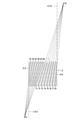
- Convergence point of the line extending the first tate-chu-bone below the lower frame bone and the convergence point of the line extending the second tate-chu-bone above the upper frame bone in the positive electrode current collector of the second embodiment is a figure which shows. It is a front view which shows the positive electrode current collector which the liquid-type lead-acid battery which concerns on 3rd Embodiment of this invention has. Convergence point of the line extending the first tate-chu-bone below the lower frame bone and the convergence point of the line extending the second tate-chu-bone above the upper frame bone in the positive electrode current collector of the third embodiment. It is a figure which shows.
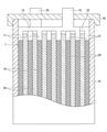
- the liquid lead-acid battery according to the present embodiment includes a electrode plate group 1 in which a plurality of positive electrode plates 10 and a negative electrode plate 20 are alternately laminated via a ribbed separator 30.
- the electrode plate group 1 is placed in the cell chamber of the electric tank 41 together with an electrolytic solution (not shown) so that the stacking direction thereof is along the horizontal direction (that is, the plate surfaces of the positive electrode plate 10 and the negative electrode plate 20 are along the vertical direction). It is housed and immersed in an electrolytic solution in the cell chamber of the electric tank 41.
- the liquid lead-acid battery according to the present embodiment has a electrode plate group 1 and an electric tank 41 provided with a cell chamber for accommodating the electrode plate group 1 together with the electrolytic solution, and one cell chamber has one.
- the electrode plate group 1 is accommodated, and the number of positive electrode plates 10 constituting the electrode plate group 1 is less than or equal to the number of negative electrode plates 20.
- the number of positive electrode plates 10 may be the same as the number of negative electrode plates 20, or may be larger than the number of negative electrode plates 20.
- the positive electrode plate 10 has a positive electrode current collector and a positive electrode mixture containing a positive electrode active material, and the positive electrode active material contains lead dioxide.
- the positive electrode current collector has a rectangular grid-like substrate and ears 11 continuous with the grid-like substrate, and the positive electrode mixture is held on the grid-like substrate.
- the negative electrode plate 20 has a negative electrode current collector and a negative electrode mixture containing a negative electrode active material, and the negative electrode active material contains metallic lead.
- the negative electrode current collector has a rectangular grid-like substrate and ears 21 continuous with the grid-like substrate, and the negative electrode mixture is held on the grid-like substrate.
- the positive electrode mixture and the negative electrode mixture are filled in the openings of the respective lattice-shaped substrates and exist as active material layers on both plate surfaces of the lattice-shaped substrate.
- the positive electrode current collector will be described in detail later.
- the negative electrode current collector constituting the negative electrode plate 20 is formed by a continuous casting method.
- Examples of the manufacturing method other than the continuous casting method of the negative electrode current collector include a lead alloy casting method, a punching method for a lead alloy rolled plate, and an expanding method using a lead alloy rolled plate.
- the separator 30 is, for example, a porous film-like body made of resin, glass, or the like, and has a flat plate-shaped base surface and, if necessary, fold-shaped ribs protruding in a direction perpendicular to the surface direction of the base surface.
- the ears 11 of the plurality of positive electrode plates 10 are connected by the positive electrode strap 13 and the ears 21 of the plurality of negative electrode plates 20 are connected by the negative electrode strap 23.
- the positive electrode strap 13 is connected to one end of the positive electrode terminal 15, the negative electrode strap 23 is connected to one end of the negative electrode terminal 25, and the other end of the positive electrode terminal 15 and the other end of the negative electrode terminal 25 are openings of the battery case 41. It penetrates the lid 43 that closes the portion and is exposed to the outside of the case body of the liquid lead storage battery including the electric tank 41 and the lid 43.
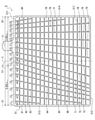
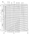
- FIG. 2 shows a first embodiment of a positive electrode current collector constituting the positive electrode plate 10.
- the positive electrode current collector 5 of the first embodiment has a horizontally long rectangular grid-like substrate 51 and ears 11 continuous with the grid-like substrate, and the positive electrode mixture is contained in the grid-like substrate 51. It is being held.
- the lattice-shaped substrate 51 has a frame bone forming four sides of a rectangle and a plurality of middle bones connected to the frame bone and existing inside the frame bone.
- the horizontal side of the rectangle forming the frame bone is longer than the vertical side.
- the frame bones are the upper frame bone 511 located above the grid-like substrate and extending laterally, the lower frame bone 512 located below the grid-like substrate and extending laterally, and the vertical frame bone located on the left side of the grid-like substrate. It has a left frame bone 513 extending in the direction and a right frame bone 514 located on the right side of the grid-like substrate and extending in the vertical direction.
- the ear 11 projects upward from a position deviated from the longitudinal center of the upper frame bone 511 toward the right frame bone 514.
- the multiple middle bones extend from the lower frame bone 512 side toward the upper frame bone 511 side while extending diagonally from the first longitudinal middle bones 61 to 65 and directly to the upper frame bone 511, and from the upper frame bone 511.
- the second longitudinal middle bone 71-80 extending diagonally toward the lower frame bone 512 side and extending parallel to the left frame bone 513 and the right frame bone 514 to connect the upper frame bone 511 and the lower frame bone 512. It is composed of a longitudinal middle bone 516 and 17 lateral middle bones 517 connecting the left frame bone 513 and the right frame bone 514.
- the transverse middle bone 517 extends parallel to the upper frame bone 511 and the lower frame bone 512.
- the cross-sectional areas of the upper frame bone 511, the left frame bone 513, and the right frame bone 514 are the first longitudinal bone 61-65, the second longitudinal media 71-80, the longitudinal media 516, and the transverse media 517. Is larger than the cross-sectional area of.
- the tate-chu-bone extending diagonally from the lower frame bone 512 side toward the upper frame bone 511 side is only the first tate-chu-bone 61 to 65, and all of them directly reach the upper frame bone 511.
- S2 distance between a pair of vertical frame bones Ratio of each distance Ln to Ls Ln / Ls, left frame Table 1 shows the angle ⁇ n formed by the first longitudinal middle bone 61 to 65, the second longitudinal middle bone 71 to 80, and the longitudinal middle bone 516 and the upper frame bone 511 on the bone 513 side.
- the distance Ls is 135 mm.
- the starting points (connection points with the upper frame bone) of the first vertical middle bones 61 to 65 are all the center (center line C) between the pair of vertical frame bones (left frame bone 513 and right frame bone 514) and the left. It exists between the frame bone (the first vertical frame bone which is the vertical frame bone on the side where the ear does not exist) 513, and does not exist between the center line C and the right frame bone 514. Further, the range in which the starting point of the first vertical middle bone 61 to 65 exists is from the left frame bone 513 to the position where the distance between the pair of vertical frame bones Ls is 7/20 (that is, the first reference line S1). Only the range up to the line C1 where the distance from is 0.35 Ls).
- the angle ⁇ 1 to ⁇ 5 formed by the first tate-chu-bone 61 to 65 and the upper frame bone 511 on the left frame bone 513 side is less than 90 °.
- the angle ⁇ 6 to ⁇ 10 between the second tate-chu bone 71 to 76 and the upper frame bone 511 on the left frame bone 513 side is less than 90 °, and the second tate-chu bone 76 to 80 and the upper frame bone 511
- the formed angles ⁇ 12 to ⁇ 16 exceed 90 °.
- the angle ⁇ 11 formed by the longitudinal middle bone 516 and the upper frame bone 511 is 90 °.
- the range in which the starting point (connection point with the upper frame bone) of the second vertical middle bone 71 to 80 exists is from the right frame bone 514 to the position where the distance between the pair of vertical frame bones Ls is 13/20. Only between (that is, the range up to the line C1 where the distance from the second reference line S2 is 0.65 Ls).
- the first longitudinal middle bones 62 to 65 connect the upper frame bone 511 and the lower frame bone 512 (the first longitudinal middle bone 62 is from the upper frame bone 511 to the lower frame bone 512 and the left frame bone 513. However, the first longitudinal middle bone 61 does not reach the lower frame bone 512, and connects the upper frame bone 511 and the lateral middle bone 517.
- the second tate-chu bones 71 to 78 connect the upper frame bone 511 and the lower frame bone 512, but the second tate-chu bones 79 and 80 do not reach the lower frame bone 512 and are connected to the upper frame bone 511. It is connected to the right frame bone 514.
- the positive electrode current collector 5 of the first embodiment is formed by punching a rolled plate made of a lead alloy. Examples of the manufacturing method other than the punching method of the positive electrode current collector include a lead alloy casting method and an expanding method using a lead alloy rolled plate.
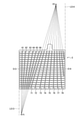
- FIG. 4 shows a second embodiment of the positive electrode current collector constituting the positive electrode plate 10.
- the positive electrode current collector of the second embodiment has a different design of the vertical middle bone from the positive electrode current collector of the first embodiment, but is the same except for the design.
- the plurality of middle bones extend diagonally from the lower frame bone 512 side toward the upper frame bone 511 side and extend to the upper frame bone 511.
- the first longitudinal middle bone 61-66 directly leading to, the second longitudinal middle bone 71-80 extending diagonally from the upper frame bone 511 toward the lower frame bone 512 side, the left frame bone 513 and the right frame. It is composed of 17 transverse medial bones 517 connecting the bones 514.
- the transverse middle bone 517 extends parallel to the upper frame bone 511 and the lower frame bone 512.
- the cross-sectional area of the upper frame bone 511, the left frame bone 513, and the right frame bone 514 is larger than the cross-sectional areas of the first longitudinal middle bone 61-66, the second longitudinal middle bone 71-80, and the lateral middle bone 517. .. Further, the tate-chu-bone extending diagonally from the lower frame bone 512 side toward the upper frame bone 511 side is only the first tate-chu-bone 61 to 66, and all of them directly reach the upper frame bone 511.
- the distance Ln from the first reference line (the line indicating the center position in the width direction of the left frame bone 513) S1 of the first longitudinal middle bone 61 to 66 and the second longitudinal middle bone 71 to 80, the first reference line S1 and the like.
- Second reference line (line indicating the center position in the width direction of the right frame bone 514) Distance from S2 (pair of vertical frame bone distances) Ratio of each distance Ln to Ls Ln / Ls, first on the left frame bone 513 side
- Table 2 shows the angle ⁇ n formed by the vertical middle bones 61 to 66 and the second vertical middle bones 71 to 80 and the upper frame bone 511.
- the distance Ls is 135 mm.
- the starting points (connection points with the upper frame bone) of the first vertical middle bones 61 to 66 are all the center (center line C) between the pair of vertical frame bones (left frame bone 513 and right frame bone 514) and the left. It exists between the frame bone (the first vertical frame bone which is the vertical frame bone on the side where the ear does not exist) 513, and does not exist between the center line C and the right frame bone 514. Further, the range in which the starting point of the first vertical middle bone 61 to 66 exists is from the left frame bone 513 to the position where the distance between the pair of vertical frame bones Ls is 9/20 (that is, the first reference line S1). Only the range up to the line C1 where the distance from is 0.45 Ls).
- the angles ⁇ 1 to ⁇ 6 formed by the first tate-chu-bone 61 to 66 and the upper frame bone 511 on the left frame bone 513 side are less than 90 °.
- the angle ⁇ 7 to ⁇ 12 between the second tate-chu bone 71 to 76 and the upper frame bone 511 on the left frame bone 513 side is less than 90 °, and the second tate-chu bone 77 to 80 and the upper frame bone 511
- the formed angles ⁇ 13 to ⁇ 16 exceed 90 °.
- the range in which the starting point (connection point with the upper frame bone) of the second vertical middle bone 71 to 80 exists is from the right frame bone 514 to the position where the distance between the pair of vertical frame bones Ls is 11/20. Only between (that is, the range up to the line C1 where the distance from the second reference line S2 is 0.55 Ls).
- the first tate-chu bones 63 to 66 connect the upper frame bone 511 and the lower frame bone 512, but the first tate-chu bones 61 and 62 do not reach the lower frame bone 512 and are connected to the upper frame bone 511. It is connected to the lateral middle bone 517.
- the second tate-chu bones 71 to 78 connect the upper frame bone 511 and the lower frame bone 512, but the second tate-chu bones 79 and 80 do not reach the lower frame bone 512 and are connected to the upper frame bone 511. It is connected to the lateral middle bone 517. As shown in FIG. 3, the line extending the first tate-chu-bone 61 to 66 below the lower frame bone 512 converges to one point.
- This convergence point P1 is outside the extension line L513 of the left frame bone 513. Further, the line extending the second vertical middle bone 71 to 80 upward from the upper frame bone 511 converges to one point. This convergence point P2 is inside the extension line L514 of the right frame bone 514.
- FIG. 6 shows a third embodiment of the positive electrode current collector constituting the positive electrode plate 10.
- the positive electrode current collector of the third embodiment has a different design of the vertical middle bone from the positive electrode current collector of the first embodiment, but is the same except for the design.
- the plurality of middle bones extend diagonally from the lower frame bone 512 side toward the upper frame bone 511 side and extend to the upper frame bone 511.
- the first longitudinal middle bone 61-66 directly leading to, the second longitudinal middle bone 71-77 extending diagonally from the upper frame bone 511 toward the lower frame bone 512 side, the reinforcing bone 91, and the left frame. It is composed of 17 lateral middle bones 517 that connect the bone 513 and the right frame bone 514.
- the transverse middle bone 517 extends parallel to the upper frame bone 511 and the lower frame bone 512.
- the cross-sectional areas of the upper frame bone 511, the left frame bone 513, and the right frame bone 514 are the first longitudinal middle bone 61-66, the second longitudinal middle bone 71-77, the transverse middle bone 517, and the reinforcing bone 91. Larger than the cross-sectional area. Further, the tate-chu-bone extending diagonally from the lower frame bone 512 side toward the upper frame bone 511 side is only the first tate-chu-bone 61 to 66, and all of them directly reach the upper frame bone 511.
- the distance Ln from the first reference line (the line indicating the center position in the width direction of the left frame bone 513) S1 of the first longitudinal middle bones 61 to 66 and the second longitudinal middle bones 71 to 77, and the first reference line S1.
- Second reference line (line indicating the center position in the width direction of the right frame bone 514)
- Distance from S2 (pair of vertical frame bone distances) Ratio of each distance Ln to Ls Ln / Ls, first on the left frame bone 513 side
- Table 3 shows the angle ⁇ n formed by the vertical middle bones 61 to 66 and the second vertical middle bones 71 to 77 and the upper frame bone 511.
- the distance Ls is 135 mm.
- the starting points (connection points with the upper frame bone) of the first vertical middle bones 61 to 66 are all the center (center line C) between the pair of vertical frame bones (left frame bone 513 and right frame bone 514) and the left. It exists between the frame bone (the first vertical frame bone which is the vertical frame bone on the side where the ear does not exist) 513, and does not exist between the center line C and the right frame bone 514. Further, the range in which the starting point of the first vertical middle bones 61 to 66 exists is from the left frame bone 513 to the position where the distance between the pair of vertical frame bones is 9/20 (that is, from the reference line S1). Only the range up to the line C1 where the distance is 0.45 Ls).
- the angles ⁇ 1 to ⁇ 6 formed by the first tate-chu-bone 61 to 66 and the upper frame bone 511 on the left frame bone 513 side are less than 90 °.
- the angle ⁇ 7 to ⁇ 13 formed by the second longitudinal middle bones 71 to 77 and the upper frame bone 511 on the left frame bone 513 side is less than 90 °.
- the angle ⁇ 14 formed by the reinforcing bone 91 and the lateral middle bone 517 on the left frame bone 513 side is larger than ⁇ 13 and less than 90 °.
- the range in which the starting point of the second vertical middle bone 71 to 77 exists is from the right frame bone 514 to the position where the distance between the pair of vertical frame bones is 11/20 (that is, the second reference line S2). Only the range up to the line C1 where the distance from is 0.55 Ls).
- All of the first tate-chu-bones 61 to 66 connect the upper frame bone 511 and the lower frame bone 512. All of the second longitudinal middle bones 71 to 77 connect the upper frame bone 511 and the lower frame bone 512.
- the reinforcing bone 91 connects the lower frame bone 512 and the transverse middle bone 517.
- the line extending the first tate-chu-bone 61 to 66 below the lower frame bone 512 converges to one point.
- This convergence point P1 is inside the extension line L513 of the left frame bone 513.
- the lines extending the second longitudinal middle bones 71 to 77 and the reinforcing bones 91 upward from the upper frame bones 511 converge to one point.
- This convergence point P2 is outside the extension line L514 of the right frame bone 514.
- FIG. 8 shows a fourth embodiment of the positive electrode current collector constituting the positive electrode plate 10.
- the positive electrode current collector of the fourth embodiment has a different design of the vertical middle bone from the positive electrode current collector of the first embodiment, but is the same except for the design.
- the plurality of middle bones extend diagonally from the lower frame bone 512 side toward the upper frame bone 511 side and extend to the upper frame bone 511.
- the first longitudinal middle bone 61-66 directly leading to, the second longitudinal middle bone 71-77 extending diagonally from the upper frame bone 511 toward the lower frame bone 512 side, the reinforcing bone 91, and the left frame. It is composed of 17 lateral middle bones 517 that connect the bone 513 and the right frame bone 514.
- the transverse middle bone 517 extends parallel to the upper frame bone 511 and the lower frame bone 512.
- the cross-sectional areas of the upper frame bone 511, the left frame bone 513, and the right frame bone 514 are the first longitudinal middle bone 61-66, the second longitudinal middle bone 71-77, the transverse middle bone 517, and the reinforcing bone 91. Larger than the cross-sectional area. Further, the tate-chu-bone extending diagonally from the lower frame bone 512 side toward the upper frame bone 511 side is only the first tate-chu-bone 61 to 66, and all of them directly reach the upper frame bone 511.
- the distance Ln from the first reference line (the line indicating the center position in the width direction of the left frame bone 513) S1 of the first longitudinal middle bones 61 to 66 and the second longitudinal middle bones 71 to 77, and the first reference line S1.
- Second reference line (line indicating the center position in the width direction of the right frame bone 514)
- Distance from S2 (pair of vertical frame bone distances) Ratio of each distance Ln to Ls Ln / Ls, first on the left frame bone 513 side
- Table 4 shows the angle ⁇ n formed by the vertical middle bones 61 to 66 and the second vertical middle bones 71 to 77 and the upper frame bone 511.
- the distance Ls is 135 mm.
- the starting points (connection points with the upper frame bone) of the first vertical middle bones 61 to 66 are all the center (center line C) between the pair of vertical frame bones (left frame bone 513 and right frame bone 514) and the left. It exists between the frame bone (the first vertical frame bone which is the vertical frame bone on the side where the ear does not exist) 513, and does not exist between the center line C and the right frame bone 514. Further, the range in which the starting point of the first vertical middle bone 61 to 66 exists is from the left frame bone 513 to the position where the distance between the pair of vertical frame bones is 9/20 (that is, from the reference line S1). Only the range up to the line C1 where the distance is 0.45 Ls).
- angles ⁇ 1 to ⁇ 6 formed by the first vertical middle bones 61 to 66 and the upper frame bone 511 on the left frame bone 513 side are 90 ° or less.
- the angle ⁇ 14 formed by the reinforcing bone 91 and the lateral middle bone 517 on the left frame bone 513 side is larger than ⁇ 13 and less than 90 °.
- the range in which the starting point of the second vertical middle bone 71 to 77 exists is from the right frame bone 514 to the position where the distance between the pair of vertical frame bones is 11/20 (that is, the second reference line S2). Only the range up to the line C1 where the distance from is 0.55 Ls). All of the first tate-chu-bones 61 to 66 connect the upper frame bone 511 and the lower frame bone 512.
- the second longitudinal middle bones 71 to 77 connect the upper frame bone 511 and the lower frame bone 512.
- the reinforcing bone 91 connects the lower frame bone 512 and the transverse middle bone 517. As shown in FIG. 9, the line extending the first tate-chu-bone 63 to 66 below the lower frame bone 512 converges to one point.
- This convergence point P1 is outside the extension line L513 of the left frame bone 513. Further, the lines extending the second longitudinal middle bones 71 to 77 and the reinforcing bones 91 upward from the upper frame bones 511 converge to one point. This convergence point P2 is outside the extension line L514 of the right frame bone 514.
- FIG. 10 shows a fifth embodiment of the positive electrode current collector constituting the positive electrode plate 10.
- the positive electrode current collector of the fifth embodiment has a different design of the vertical middle bone from the positive electrode current collector of the first embodiment, but is the same except for the design.
- the plurality of middle bones extend diagonally from the lower frame bone 512 side toward the upper frame bone 511 side and extend to the upper frame bone 511.
- the first longitudinal middle bone 61-66 directly leading to, the second longitudinal middle bone 71-80 extending diagonally from the upper frame bone 511 toward the lower frame bone 512 side, the left frame bone 513 and the right frame. It is composed of 17 transverse medial bones 517 connecting the bones 514.
- the transverse middle bone 517 extends parallel to the upper frame bone 511 and the lower frame bone 512.
- the cross-sectional areas of the upper frame bone 511, the left frame bone 513, and the right frame bone 514 are larger than the cross-sectional areas of the first longitudinal middle bone 61-66, the second longitudinal middle bone 71-80, and the lateral middle bone 517.
- the tate-chu-bone extending diagonally from the lower frame bone 512 side toward the upper frame bone 511 side is only the first tate-chu-bone 61 to 66, and all of them directly reach the upper frame bone 511.
- the distance Ln from the first reference line (the line indicating the center position in the width direction of the left frame bone 513) S1 of the first longitudinal middle bone 61 to 66 and the second longitudinal middle bone 71 to 80, the first reference line S1 and the like.
- Second reference line (line indicating the center position in the width direction of the right frame bone 514) Distance from S2 (pair of vertical frame bone distances) Ratio of each distance Ln to Ls Ln / Ls, first on the left frame bone 513 side
- Table 5 shows the angle ⁇ n formed by the vertical middle bones 61 to 66 and the second vertical middle bones 71 to 80 and the upper frame bone 511.
- the distance Ls is 135 mm.
- the starting points (connection points with the upper frame bone) of the first vertical middle bones 61 to 66 are all the center (center line C) between the pair of vertical frame bones (left frame bone 513 and right frame bone 514) and the left. It exists between the frame bone (the first vertical frame bone which is the vertical frame bone on the side where the ear does not exist) 513, and does not exist between the center line C and the right frame bone 514. Further, the range in which the starting point of the first vertical middle bone 61 to 66 exists is from the left frame bone 513 to the position where the distance between the pair of vertical frame bones is 9/20 (that is, from the reference line S1). Only the range up to the line C1 where the distance is 0.45 Ls). Further, the angles ⁇ 1 to ⁇ 6 formed by the first vertical middle bones 61 to 66 and the upper frame bone 511 on the left frame bone 513 side are 90 ° or less.
- the range in which the starting point of the second vertical middle bone 71 to 80 exists is from the right frame bone 514 to the position where the distance between the pair of vertical frame bones is 11/20 (that is, the second reference line S2). Only the range up to the line C1 where the distance from is 0.55 Ls). All of the first tate-chu-bones 61 to 66 connect the upper frame bone 511 and the lower frame bone 512.
- the second tate-chu bones 71 to 78 connect the upper frame bone 511 and the lower frame bone 512, but the second tate-chu bones 79 and 80 do not reach the lower frame bone 512 and are connected to the upper frame bone 511. It is connected to the lateral middle bone 517. As shown in FIG.
- the line extending the first tate-chu-bone 61 to 66 below the lower frame bone 512 converges to one point.
- This convergence point P1 is inside the extension line L513 of the left frame bone 513.
- the line extending the second vertical middle bone 71 to 80 upward from the upper frame bone 511 converges to one point.
- This convergence point P2 is inside the extension line L514 of the right frame bone 514.
- the plurality of middle bones are 16 vertical middle bones 516 connecting the upper frame bone 511 and the lower frame bone 512, and the left frame bone 513 and the right. It is composed of 17 lateral middle bones 517 connecting to the frame bone 514.
- the tate-chu-bone 516 extends parallel to the left frame bone 513 and the right frame bone 514. That is, in this example, there is no first tate-chu-bone extending diagonally from the lower frame bone 512 side toward the upper frame bone 511 side and directly reaching the upper frame bone 511, and below the upper frame bone 511. There is also no second tate-chu-bone that extends diagonally toward the frame bone 512 side.
- the transverse middle bone 517 extends parallel to the upper frame bone 511 and the lower frame bone 512.
- the cross-sectional area of the upper frame bone 511, the left frame bone 513, and the right frame bone 514 is larger than the cross-sectional area of the longitudinal middle bone 516, the lateral middle bone 517, and the reinforcing bone 91.
- Distance Ln from the first reference line (line indicating the center position in the width direction of the left frame bone 513) S1 of the 16 longitudinal middle bones 516, the first reference line S1 and the second reference line (width direction of the right frame bone 514) Line indicating the center position)
- Distance from S2 (distance between a pair of vertical frame bones) Ratio of each distance Ln to Ls Ln / Ls, angle ⁇ n between the vertical middle bone 516 and the upper frame bone 511 on the left frame bone 513 side (All 90 °) are shown in Table 6.
- the distance Ls is 135 mm.
- the plurality of middle bones are the second longitudinal middle bones 71 to 85 extending diagonally from the upper frame bone 511 toward the lower frame bone 512 side.
- the longitudinal middle bone 516 extending parallel to the left frame bone 513 and the right frame bone 514 and connecting the upper frame bone 511 and the lower frame bone 512, and 17 pieces connecting the left frame bone 513 and the right frame bone 514. It is composed of the lateral middle bone 517. That is, in this example, there is no first tate-chu-bone extending diagonally from the lower frame bone 512 side toward the upper frame bone 511 side and directly reaching the upper frame bone 511.
- the transverse middle bone 517 extends parallel to the upper frame bone 511 and the lower frame bone 512.
- the cross-sectional areas of the upper frame bone 511, the left frame bone 513, and the right frame bone 514 are larger than the cross-sectional areas of the longitudinal middle bone 516, the second longitudinal middle bones 71-85, and the transverse middle bone 517.
- the starting point (connection point with the upper frame bone) of the second vertical middle bones 71 to 86 is a position at 11/20 of the pair of vertical frame bone distances Ls from the right frame bone 514 (that is, the second reference line S2). It also exists in the range outside the line C1) where the distance from the line C1) is 0.55 Ls. Further, the angles ⁇ 1 to ⁇ 11 and ⁇ 13 to ⁇ 16 formed by the second vertical middle bones 71 to 85 and the upper frame bone 511 on the left frame bone 513 side are less than 90 °.
- the second tate-chu bones 74 to 84 connect the upper frame bone 511 and the lower frame bone 512
- the second tate-chu bones 71 to 73 connect the upper frame bone 511 and the left frame bone 513
- the second The longitudinal middle bone 85 of the above connects the upper frame bone 511 and the right frame bone 514.
- the line extending the second vertical middle bones 71 to 85 and the vertical middle bone 516 above the upper frame bone 511 converges to one point on the extension line of the vertical middle bone 516. That is, this convergence point is between the extension line of the left frame bone 513 and the extension line of the right frame bone 514 (just above the ear 11).
- the plurality of middle bones extend diagonally from the lower frame bone 512 side toward the upper frame bone 511 side and extend directly to the upper frame bone 511.
- Nine longitudinal middle bones 516 extending parallel to the left frame bone 513 and the right frame bone 514 and connecting the upper frame bone 511 and the lower frame bone 512, and the upper frame from the lower frame bone 512 side.
- Reinforcing bones 92 to 94 extending diagonally toward the bone 511 side and reaching the longitudinal middle bone 516A closest to the left frame bone 513, and 17 lateral bones connecting the left frame bone 513 and the right frame bone 514. It is composed of a middle bone 517 and.
- the transverse middle bone 517 extends parallel to the upper frame bone 511 and the lower frame bone 512.
- the upper frame bone 511 there is no second tate-chu-bone extending diagonally from the upper frame bone 511 toward the lower frame bone 512 side.
- the upper frame bone 511 It has reinforcing bones 92 to 94 that do not reach directly but reach the longitudinal middle bone 516A.
- the cross-sectional areas of the upper frame bone 511, the left frame bone 513, and the right frame bone 514 are 9 longitudinal middle bones 516, the first longitudinal middle bones 61-64, the reinforcing bones 92-94, and the transverse middle bone 517. Larger than the cross-sectional area.
- the starting points (connection points with the upper frame bone) of the first vertical middle bones 61 to 64 are all the center (center line C) between the pair of vertical frame bones (left frame bone 513 and right frame bone 514) and the left. It exists between the frame bone (the first vertical frame bone which is the vertical frame bone on the side where the ear does not exist) 513, and does not exist between the center line C and the right frame bone 514. Further, the range in which the starting point of the first vertical middle bone 61 to 64 exists is from the left frame bone 513 to the position where the distance between the pair of vertical frame bones Ls is 9/20 (that is, the first reference line S1). Only the range up to the line C1 where the distance from is 0.45 Ls).
- angles ⁇ 1 to ⁇ 4 formed by the first tate-chu-bone 61 to 64 and the upper frame bone 511 on the left frame bone 513 side are less than 90 °.
- the angle ⁇ 92 to ⁇ 94 formed by the reinforcing bones 92 to 94 and the lateral middle bone 517 on the left frame bone 513 side is less than 90 ° and smaller than ⁇ 4.
- the positive electrode current collectors of the first to fifth embodiments satisfy all of the following (a) to (d).
- (a) At least a part of the plurality of tate-chu-bones existing in the range between the center between the pair of vertical frame bones and the first vertical frame bone which is the vertical frame bone on the side where the ear does not exist. Is the first tate-chu-bone that extends diagonally from the lower frame bone side toward the upper frame bone side and directly reaches the upper frame bone.
- All the tate-chu-bone extending diagonally from the lower frame bone side toward the upper frame bone side directly reaches the upper frame bone.
- the angle between the first vertical middle bone and the upper frame bone on the side of the first vertical frame bone is less than 90 °. That is, the first tate-chuboshi spreads toward the ear.
- the connection point of the first tate-chu-bone with the upper frame bone is between the center between the pair of vertical frame bones and the first vertical frame bone which is the vertical frame bone on the side where the ear does not exist. Exists only in the range of.
- the positive electrode current collector of Comparative Example 1 does not satisfy all of the above (a) to (d).
- the positive electrode current collector of Comparative Example 2 does not satisfy all of the above (a) to (d).
- Comparative Example 2 is a liquid-type lead-acid battery described in Patent Document 1, and the positive electrode grid is formed in a shape in which all the vertical middle bones are spaced apart from the selvage in the left-right direction.
- the positive electrode current collector of Comparative Example 2 has a better in-plane potential distribution than the positive electrode current collector of Comparative Example 1, but the area of the opening becomes larger as the distance from the ear increases, so that the positive electrode collector vibrates when used in a vehicle. When an impact is applied, the discharge capacity is reduced by the amount of the active material that has fallen off, and the life is shortened.
- the positive electrode current collector of Comparative Example 3 does not satisfy the above (b).
- the positive electrode current collector of Comparative Example 3 is a lattice body described in Patent Document 2, and in a liquid lead-acid battery having this lattice body, when a large current is to be taken out for an application such as engine starting, as described above, as described above. A large current is concentrated on the vertical center bone 516A and corrosion progresses, which may cause a sharp deterioration in battery performance.
- the positive electrode current collectors of the first to fifth embodiments satisfy all of the above (a) to (d), so that the potential distribution of the positive electrode grid is good and the take-out current is high. Stable performance can be obtained.
- the angle formed by the first vertical middle bone and the upper frame bone on the side of the first vertical frame bone is preferably 45 ° or more and less than 90 °, and more preferably 70 ° or more and less than 90 °.
- the range in which the starting point of the first tate-chu-bone exists is only from the left frame bone 513 to the position where the distance between the pair of vertical frame bones Ls is 9/20 (that is, the above (d)).
- the range in which the starting point (connection point with the upper frame bone) of the second vertical middle bone exists is from the right frame bone 514 to the position where the distance between the pair of vertical frame bones is 11/20. Only.
- the opening composed of the longitudinal bone, the frame bone, and the transverse media bone that occurs on the spreading side of the first longitudinal bone and the second longitudinal bone becomes an appropriate size. Therefore, there is no inconvenience associated with the installation of reinforcing bones.
- the starting point of the first tate-chu-bone is preferably located within a range from the left frame bone 513 to a position equal to or more than 1/5 of the pair of vertical frame bone distances Ls and not more than a position to be 1/2.
- the line having convergence points P1 and P2 that is, the line extending the first tate-chu bone below the lower frame bone 512 converges to one point, and the second tate-chu bone extends above the upper frame bone 511. Since the drawn lines converge to one point, the potential distribution is better than when they do not converge. In addition, since the design can be easily changed, it is possible to easily develop a wide variety of products. Further, when the rectangle forming the frame bone of the positive electrode collector has a horizontally long shape in which the horizontal side is longer than the vertical side, the grid-like substrate of the positive electrode collector tends to have a large lateral growth. ..
- the left and right frame bones of the expanding positive electrode plate may stretch and tear the separator in contact with the separator. Even if the separator is not torn, a part of the positive electrode lattice broken by corrosion may break through the separator. As a result, the positive electrode and the negative electrode stacked on each other via the separator may be contact-short-circuited, and the life may be reached at an early stage.
- the grid-like substrate of the positive electrode current collector has a horizontally long shape, but by satisfying all of the above (a) to (d), a remarkable potential distribution improving effect is achieved. Can be obtained and the early life can be prevented.
- the number of the first tate-chu-bone directly connected to the upper frame bone is the first to the first. Since the positive current collector 5 of the four embodiments is larger than the positive current collector 50B of Comparative Example 3, the amount of current collected toward the upper frame bone having a large cross-sectional area increases, so that the current is collected in the vertical direction. Bone is less likely to corrode.
- the first longitudinal bone 61 constituting the positive electrode current collector of the first embodiment and the first longitudinal central bones 61 and 62 constituting the positive electrode current collectors of the second embodiment and the third embodiment are ,
- the differences in action and effect due to the difference in the design of the vertical middle bone in the positive electrode current collectors of the first to fifth embodiments are as follows.
- the lead-acid battery using the positive electrode current collectors of the first embodiment and the second embodiment is superior to the third embodiment and the fourth embodiment because the second longitudinal bones are concentrated toward the upper part of the ear.
- the current collection characteristics and cycle life characteristics can be obtained.
- the range in which the starting point of the first longitudinal bone exists is 7/20 of the pair of longitudinal frame bone distances Ls from the left frame bone 513 in the first embodiment.
- the range in which the starting point of the second tate-chu-bone exists is 13/20 of the pair of vertical-frame bone distances Ls from the right frame bone 514, which is narrower than that of the second embodiment. It is wider than the second embodiment only up to the position. Therefore, in the normal placement density, the opening composed of the longitudinal middle bone, the frame bone, and the transverse middle bone generated on the spreading side of the first longitudinal bone and the second longitudinal bone is the first embodiment. Since the size of the second embodiment is more appropriate than that of the second embodiment, it is further advantageous in that inconveniences associated with the installation of reinforcing bones do not occur.
- the lead-acid battery using the positive electrode current collector of the third embodiment is held in the opening because the average opening area of the opening formed by the first longitudinal bone is smaller than that of the other embodiments. Although it is easy to prevent the positive electrode mixture from peeling off or falling off, the average opening area of the opening near the ear is larger than that of the first embodiment and the second embodiment, so that the current collection characteristics and the cycle life characteristics are improved. , Slightly inferior to the first and second embodiments.
- the lead-acid battery using the positive electrode current collector of the fourth embodiment has a smaller variation in the opening area of the opening as compared with the first to third embodiments, so that the positive electrode mixture can be locally peeled off or dropped off. Although it is easy to prevent, the cycle life characteristics for the idling stop vehicle are slightly inferior to those of the first to third embodiments.
- the second longitudinal bones are concentrated toward the upper part of the ear, and therefore, the third embodiment. And the current collection characteristics and the cycle life characteristics superior to those of the fourth embodiment can be obtained. Further, in the lead storage battery using the positive electrode current collector of the fifth embodiment, as in the third embodiment, the average opening area of the opening formed by the first longitudinal bone is larger than that of the other embodiments. Since the size is small, it is easy to prevent the positive electrode mixture held in the opening from peeling off or falling off.
- the cross-sectional area of the upper frame bone 511 is 235% to 300% with respect to the average cross-sectional area of the transverse middle bone 517, and a plurality of pieces in contact with the upper frame bone 511.
- the area of each opening in a plan view of the above is preferably 50% to 75% with respect to the average opening area of all the openings of the grid-like substrate 51.
- the average diameter of the pores of the positive electrode mixture is preferably 0.15 ⁇ m or more and 0.40 ⁇ m or less.
- the porosity of the positive electrode mixture is preferably 30% or more and 50% or less. If the pore diameter of the positive electrode mixture is less than 0.15 ⁇ m, the utilization rate of the positive electrode active material may decrease. On the other hand, if the average diameter of the positive electrode mixture is larger than 0.40 ⁇ m, the internal resistance of the liquid lead-acid battery may increase. In addition, softening of the positive electrode mixture may easily occur.
- the method for measuring the average diameter of the pores of the positive electrode mixture is not particularly limited, but it can be measured by, for example, a mercury intrusion method. If the porosity of the positive electrode mixture is less than 30%, sulfuric acid may not easily permeate into the mixture, and the utilization rate of the active material may decrease. On the other hand, if the porosity of the positive electrode mixture exceeds 50%, the density of the mixture decreases, which may shorten the cycle life.
- the cross-sectional areas of the second tate-chu bones 74 to 76 and the tate-chu-bone 516 connected to the lower part of the ear 11 are the cross-sectional areas of all the tate-chu-bones. It is preferably 1.26 times or more and 1.50 times or less.
- Liquid lead-acid batteries (samples No. 1 to No. 25) having a battery size of Q-85 were produced by the following method. As shown in Table 1, the liquid lead-acid batteries of Samples No. 1 to No. 25 have different configurations of the upper frame bone of the positive electrode current collector and the openings in contact with the upper frame bone, except for the other points. It is the same.
- the liquid lead-acid batteries of Samples No. 1 to No. 25 have a width (horizontal dimension) of 135 mm and a height of the grid-like substrate 51 in the positive electrode current collector 5.
- current collectors (lattice-shaped substrate + ear) for the positive electrode plate and the negative electrode plate were manufactured by a punching method from a rolled plate made of a Pb—Ca—Sn alloy. A rolled structure with an average interlayer distance of 20 ⁇ m was observed in the cross section of the current collector cut in the thickness direction.
- the weight of each positive electrode current collector is 40.0 g.
- the thickness of the middle bone was changed at the same time so that the weight of the positive electrode current collector was the same among all the samples.
- all the lateral middle bones 517 have the same thickness.
- the average cross-sectional area of all the transverse middle bones 517 is 1.00 mm 2
- the average cross-sectional area of the upper frame bone 511 is 2.00 mm 2 .
- the opening area of the openings in contact with the upper frame bone 511 in a plan view is 45%, 50%, 65%, 75%, and 80%, respectively, with respect to the average opening area in a plan view of all the openings.
- the average opening area of the opening in contact with the upper frame bone 511 was adjusted by changing the separation distance between the lateral middle bones 517. At this time, the distance between the lateral middle bones 517 was adjusted to be even.
- the positive electrode current collectors 5 of the liquid lead-acid batteries of Samples No. 6 to No. 10 have a cross-sectional area of 2.23 mm 2 of the upper frame bone 511 constituting the grid-like substrate 51, and all the lateral middle bones.
- the cross-sectional area of 517 is 0.95 mm2. That is, the thickness ratio of the upper frame bone 511 to the lateral middle bone 517 is 235%.
- the average opening area of the openings in contact with the upper frame bone 511 in a plan view is 45%, 50%, 65%, 75%, and 80%, respectively, with respect to the average opening area in a plan view of all the openings.
- the average opening area of the opening in contact with the upper frame bone 511 was adjusted by changing the separation distance between the lateral middle bones 517. At this time, the distance between the lateral middle bones 517 was adjusted to be even.
- the positive electrode current collectors 5 of the liquid lead-acid batteries of Samples No. 11 to No. 15 have a cross-sectional area of 2.43 mm 2 of the upper frame bone 511 constituting the grid-like substrate 51, and all the lateral middle bones.
- the cross-sectional area of 517 is 0.90 mm2. That is, the thickness ratio of the upper frame bone 511 to the lateral middle bone 517 is 270%.
- the average opening area of the openings in contact with the upper frame bone 511 in a plan view is 45%, 50%, 65%, 75%, and 80%, respectively, with respect to the average opening area in a plan view of all the openings.
- the average opening area of the opening in contact with the upper frame bone 511 was adjusted by changing the separation distance between the lateral middle bones 517. At this time, the distance between the lateral middle bones 517 was adjusted to be even.
- the positive electrode current collectors 5 of the liquid lead-acid batteries of Samples No. 16 to No. 20 have a cross-sectional area of 2.55 mm 2 of the upper frame bone 511 constituting the grid-like substrate 51, and all the lateral middle bones.
- the cross-sectional area of 517 is 0.85 mm 2 . That is, the thickness ratio of the upper frame bone 511 to the lateral middle bone 517 is 300%.
- the average opening area of the openings in contact with the upper frame bone 511 in a plan view is 45%, 50%, 65%, 75%, and 80%, respectively, with respect to the average opening area in a plan view of all the openings.
- the average opening area of the opening in contact with the upper frame bone 511 was adjusted by changing the separation distance between the lateral middle bones 517. At this time, the distance between the lateral middle bones 517 was adjusted to be even.
- the positive electrode current collectors 5 of the liquid lead-acid batteries of Samples No. 21 to No. 25 have a cross-sectional area of 2.56 mm 2 of the upper frame bone 511 constituting the grid-like substrate 51, and all the lateral middle bones.
- the cross-sectional area of 517 is 0.80 mm2. That is, the thickness ratio of the upper frame bone 511 to the lateral middle bone 517 is 320%.
- the average opening area of the openings in contact with the upper frame bone 511 in a plan view is 45%, 50%, 65%, 75%, and 80%, respectively, with respect to the average opening area in a plan view of all the openings.
- the average opening area of the opening in contact with the upper frame bone 511 was adjusted by changing the separation distance between the lateral middle bones 517. At this time, the distance between the lateral middle bones 517 was adjusted to be even.
- the configuration of the plurality of cores constituting the grid-like substrate 51 is the same as that of the positive electrode current collector 5 of the first embodiment shown in FIG. ..
- the negative electrode current collectors of Samples No. 1 to No. 25 those having the same shape and the same cross-sectional area as the positive electrode current collector 5 of Sample No. 1 were used.
- lead powder containing lead monoxide as a main component was kneaded with water and dilute sulfuric acid, and if necessary, additives were mixed and kneaded to prepare a paste for a positive electrode mixture.
- the ratio ⁇ / ( ⁇ + ⁇ ) of the mass ⁇ of ⁇ -lead dioxide and the mass ⁇ of ⁇ -lead dioxide contained in the positive electrode active material after chemical conversion was set to 20%.
- lead powder containing lead monoxide as a main component was kneaded with water and dilute sulfuric acid, and if necessary, additives were mixed and kneaded to prepare a paste for a negative electrode mixture.
- the density of the positive electrode mixture contained in the positive electrode plate was 4.2 g / cm 3
- the density of the negative electrode mixture contained in the negative electrode plate was 4.0 g / cm 3
- the average pore diameter of the positive electrode mixture was 0.20 ⁇ m, and the porosity was 40%.
- a ribbed separator made of a porous synthetic resin and having a flat plate-shaped base surface and fold-shaped ribs protruding in a direction orthogonal to the surface direction of the base surface was prepared.
- the total thickness of the ribbed separator was 0.90 mm
- the rib height was 0.65 mm
- the base surface thickness was 0.25 mm.
- a plurality of prepared positive electrode plates and negative electrode plates before chemical conversion were alternately laminated with a ribbed separator interposed therebetween to prepare a group of electrode plates.
- the number of positive electrode plates was 7, and the number of negative electrode plates was 8.
- This group of electrode plates was housed in an electric tank, the ears of the positive electrode collector of each positive electrode plate were connected by a positive electrode strap, and the ears of the negative electrode collector of each negative electrode plate were connected by a negative electrode strap. Then, the positive electrode strap was connected to one end of the positive electrode terminal, and the negative electrode strap was connected to one end of the negative electrode terminal.
- the electric tank has a plurality of cell chambers for accommodating the electrode plate group, and the volume of the portion below the upper level (maximum liquid level line) per cell chamber is 570 cm 3 .
- a predetermined group pressure was applied to the electrode plate group.
- the opening of the electric tank was closed with a lid.
- the positive electrode pole and the negative electrode pole are each penetrated through a bushing inserted into the lid, and the other end of the positive electrode pole and the other end of the negative electrode pole are welded while being exposed to the outside of the liquid lead-acid battery, and the positive electrode is welded.
- a terminal and a negative electrode terminal were formed.
- an electrolytic solution consisting of dilute sulfuric acid having a specific gravity of 1.23 and containing aluminum sulfate at a concentration of 0.1 mol / L is injected to the upper level of the battery case, and the liquid injection port is opened. It was sealed with a stopper and electrolyzed to obtain a liquid lead-acid battery.
- the time from the injection of the electrolytic solution to the start of energization for chemical formation was 30 minutes, the amount of electricity for chemical conversion was 230%, and the temperature of the electrolytic solution at the time of chemical conversion was 45 ° C. At this time, the amount of the injected electrolytic solution was 375 cm 3 per cell chamber. The specific gravity of the electrolytic solution after chemical conversion was 1.28.
- the growth rate RY of the positive electrode grid in the vertical direction was confirmed when the life test passed 300 cycles.
- the growth rate RY of the positive electrode grid was calculated as follows. First, for the positive electrode lattice body before the life test, the distance Y 1 from the top surface of the lid to the upper frame bone is measured. This measurement may be performed via the liquid injection port formed in the lid, or may be performed by forming a communication port at an appropriate position and passing through the communication hole.
- the test is suspended and the distance Y 2 from the top surface of the lid to the upper frame bone is measured.
- the difference between Y 1 and Y 2 is obtained, and the growth rate RY in the vertical direction of the positive electrode grid is based on the height (vertical dimension) of 114.5 mm of the grid-like substrate 51 and the following equation (1). %) was calculated.
- the cross-sectional area of the upper frame bone 511 becomes the average cross-sectional area of the transverse middle bone 517.
- it is 235% to 300%, and the opening area of each of the plurality of openings in contact with the upper frame bone 511 in a plan view is 50% to 30% with respect to the average opening area of all the openings of the grid-like substrate 51. It can be seen that when it is 75%, a liquid lead-acid battery having a particularly excellent life cycle tends to be obtained.
- the growth rate RY in the vertical direction tends to be suppressed and the cycle life tends to be improved.
- the ratio of the cross-sectional area of the upper frame bone to the lateral middle bone exceeds 300%, the cycle life tends not to be improved even though the growth rate RY in the vertical direction is further suppressed. ..
- the mechanical strength of the middle bone of the positive electrode current collector was small, the deformation of the lower part of the positive electrode current collector could not be prevented, and the positive electrode mixture was peeled off or dropped off, resulting in a liquid type. It is estimated that the capacity of the lead-acid battery has decreased.
- Liquid lead-acid batteries (samples No. 26 to No. 49) having a battery size of Q-85 were produced by the following method. As shown in Table 13, the liquid lead-acid batteries of Samples No. 26 to No. 49 differ in the composition of the pore diameter ( ⁇ m) and porosity (%) of the positive electrode mixture, but the other points are samples. Same as No.8.
- the liquid lead-acid batteries of Samples No. 26 to No. 49 have a width (horizontal dimension) of 135 mm and a height of the grid-like substrate 51 in the positive electrode current collector 5. (Vertical dimension) is 114.5 mm. All of these dimensions are the distance between the centerlines of the frame bones.
- the cross-sectional areas of the left frame bone 513, the right frame bone 514, and the lower frame bone 512 are all 1.80 mm 2 .
- current collectors (lattice-shaped substrate + ear) for the positive electrode plate and the negative electrode plate were manufactured by a punching method from a rolled plate made of a Pb—Ca—Sn alloy. A rolled structure with an average interlayer distance of 20 ⁇ m was observed in the cross section of the current collector cut in the thickness direction.
- the weight of each positive electrode current collector is 40.0 g.
- the positive electrode current collector 5 included in the liquid lead-acid batteries of Samples No. 26 to No. 30 has the same configuration as that of Sample No. 8 in the grid-like substrate 51, and is a positive electrode mixture held in the grid-like substrate 51.
- the pore diameters are 0.10 ⁇ m, and the porosities are 20%, 30%, 40%, 50%, and 60%, respectively.
- the positive electrode current collector 5 included in the liquid lead-acid batteries of Samples No. 31 to No. 35 has the same configuration as that of Sample No. 8 in the grid-like substrate 51, and is a positive electrode mixture held in the grid-like substrate 51.
- the pore diameters are 0.15 ⁇ m, and the porosities are 20%, 30%, 40%, 50%, and 60%, respectively.
- the positive electrode current collector 5 included in the liquid lead-acid batteries of Samples No. 36 to No. 39 has the same configuration as that of Sample No. 8 in the grid-like substrate 51, and is a positive electrode mixture held in the grid-like substrate 51.
- the positive electrode current collector 5 included in the liquid lead-acid battery of sample No. 8 has a pore diameter of 0.15 ⁇ m and a porosity of 40%.
- the positive electrode current collector 5 contained in the liquid lead-acid batteries of Samples No. 40 to No. 44 has the same configuration as that of Sample No. 8 in the grid-like substrate 51, and is a positive electrode mixture held in the grid-like substrate 51. Has a pore diameter of 0.40 ⁇ m and a porosity of 20%, 30%, 50%, and 60%, respectively.
- the positive electrode current collectors 5 of the liquid lead-acid batteries of Samples No. 45 to No. 49 have the same structure as that of Sample No. 8 in the grid-like substrate 51, and are held in the grid-like substrate 51.
- the pore diameters are 0.45 ⁇ m, and the porosities are 20%, 30%, 50%, and 60%, respectively.
- As the negative electrode current collectors of Samples No. 26 to No. 49 those having the same shape and the same cross-sectional area as the positive electrode current collector 5 of Sample No. 8 were used.
- lead powder containing lead monoxide as a main component was kneaded with water and dilute sulfuric acid, and if necessary, additives were mixed and kneaded to prepare a paste for a positive electrode mixture.
- the ratio ⁇ / ( ⁇ + ⁇ ) of the mass ⁇ of ⁇ -lead dioxide and the mass ⁇ of ⁇ -lead dioxide contained in the positive electrode active material after chemical conversion was set to 20%.
- lead powder containing lead monoxide as a main component was kneaded with water and dilute sulfuric acid, and if necessary, additives were mixed and kneaded to prepare a paste for a negative electrode mixture.
- the density of the positive electrode mixture contained in the positive electrode plate was 4.2 g / cm 3
- the density of the negative electrode mixture contained in the negative electrode plate was 4.0 g / cm 3
- a ribbed separator made of a porous synthetic resin and having a flat plate-shaped base surface and fold-shaped ribs protruding in a direction orthogonal to the surface direction of the base surface was prepared.
- the total thickness of the ribbed separator was 0.90 mm
- the rib height was 0.65 mm
- the base surface thickness was 0.25 mm.
- a plurality of prepared positive electrode plates and negative electrode plates before chemical conversion were alternately laminated with a ribbed separator interposed therebetween to prepare a group of electrode plates.
- the number of positive electrode plates was 7, and the number of negative electrode plates was 8.
- This group of electrode plates was housed in an electric tank, the ears of the positive electrode collector of each positive electrode plate were connected by a positive electrode strap, and the ears of the negative electrode current collector of each negative electrode plate were connected by a negative electrode strap. Then, the positive electrode strap was connected to one end of the positive electrode terminal, and the negative electrode strap was connected to one end of the negative electrode terminal.
- the electric tank has a plurality of cell chambers for accommodating the electrode plate group, and the volume of the portion below the upper level (maximum liquid level line) per cell chamber is 570 cm3. In addition, a predetermined group pressure was applied to the electrode plate group.
- the opening of the electric tank was closed with a lid.
- the positive electrode pole and the negative electrode pole are each penetrated through a bushing insert-molded in the lid, and the other end of the positive electrode pole and the other end of the negative electrode pole are welded in a state of being exposed to the outside of the liquid lead-acid battery, and the positive electrode is welded.
- a terminal and a negative electrode terminal were formed.
- an electrolytic solution consisting of dilute sulfuric acid having a specific gravity of 1.23 and containing aluminum sulfate at a concentration of 0.1 mol / L is injected to the upper level of the battery case, and the liquid injection port is opened. It was sealed with a stopper and electrolyzed to obtain a liquid lead-acid battery.
- the time from the injection of the electrolytic solution to the start of energization for chemical formation was 30 minutes, the amount of electricity for chemical conversion was 230%, and the temperature of the electrolytic solution at the time of chemical conversion was 45 ° C. At this time, the amount of the injected electrolytic solution was 375 cm 3 per cell chamber.
- the specific gravity of the electrolytic solution after chemical conversion was 1.28.
- a plurality of liquid lead-acid batteries of each lot were manufactured, and it was considered that the liquid lead-acid batteries of the same lot had the same structure and battery characteristics.
- Each of the liquid lead-acid batteries of Samples No. 26 to No. 49 thus obtained was subjected to a life test at 75 ° C., and the number of cycles until the life was investigated.
- the conditions of the life test are as follows. First, in a 75 ° C environment, 300 A discharge for 2 seconds, CCCV charge for 60 minutes (14.5 V, maximum charge current 50 A), 25 A discharge for 5 minutes, CCCV charge for 30 minutes (14.5 V, maximum charge current 50 A). ) was repeated a plurality of cycles in this order, and it was determined that the life was reached when the voltage at each discharge dropped to 7.2 V, and the number of cycles performed up to that point was defined as the life.
- the results of the life test were evaluated according to the following criteria. If the number of cycles is 360 or more and less than 370, it is judged as " ⁇ ", and if it is 370 or more, it is judged to be particularly excellent and is evaluated as " ⁇ ".
- the utilization rate of the active material was determined by measuring the discharge capacity after performing a 5-hour rate discharge test. If the measured value of the discharge capacity is 32 Ah or more, which is the rated capacity of the Q-85 size liquid lead-acid battery, it is judged that the utilization rate is remarkably excellent, and the measured value of the discharge capacity is " ⁇ ".
- Liquid lead-acid batteries (samples No. 50 to No. 56) having a battery size of Q-85 were produced by the following method. As shown in Table 11, the liquid lead-acid batteries of Samples No. 50 to No. 56 have different cross-sectional areas of the tate-chu-bone having a connection point at the lower part of the ear among the tate-chu-bone of the positive electrode current collector. However, other points are the same as sample No.8.
- the liquid lead-acid batteries of Samples No. 50 to No. 56 have a width (horizontal dimension) of 135 mm and a height of the grid-like substrate 51 in the positive electrode current collector 5.
- the average opening area of the openings in contact with the upper frame bone 511 in a plan view is 65% of the average opening area in a plan view of all the openings.
- current collectors (lattice-shaped substrate + ear) for the positive electrode plate and the negative electrode plate were manufactured by a punching method from a rolled plate made of a Pb—Ca—Sn alloy. A rolled structure with an average interlayer distance of 20 ⁇ m was observed in the cross section of the current collector cut in the thickness direction.
- the weight of each positive electrode current collector is 40.0 g.
- the range in which the starting point (connecting point with the upper frame bone) of the second longitudinal middle bone 74 to 76 exists is between the position where the distance from the first reference line S1 is 80 to 105 (that is, in the lower part of the ear). The range in which it is located).
- the first tate-chu bones 63 to 66 connect the upper frame bone 511 and the lower frame bone 512, but the first tate-chu bones 61 and 62 do not reach the lower frame bone 512 and are connected to the upper frame bone 511. It is connected to the lateral middle bone 517.
- the second tate-chu bones 71 to 78 connect the upper frame bone 511 and the lower frame bone 512, but the second tate-chu bones 79 and 80 do not reach the lower frame bone 512 and are connected to the upper frame bone 511. It is connected to the lateral middle bone 517. As shown in FIG. 3, the line extending the first tate-chu-bone 61 to 66 below the lower frame bone 512 converges to one point.
- This convergence point P1 is outside the extension line L513 of the left frame bone 513. Further, the line extending the second vertical middle bone 71 to 80 upward from the upper frame bone 511 converges to one point. This convergence point P2 is inside the extension line L514 of the right frame bone 514.
- the cross-sectional areas of the second longitudinal bones 74 to 76 connected to the lower part of the ear 11 and the longitudinal medial bone 516 are all in the vertical middle. It is 1.20 times the average cross-sectional area of bone.
- the cross-sectional areas of the second longitudinal bones 74 to 76 connected to the lower part of the ear 11 and the longitudinal medial bone 516 are all in the vertical middle. It is 1.26 times the average cross-sectional area of bone.
- the cross-sectional areas of the second longitudinal bones 74 to 76 connected to the lower part of the ear 11 and the longitudinal medial bone 516 are all in the vertical middle. It is 1.30 times the average cross-sectional area of bone.
- the cross-sectional areas of the second longitudinal bones 74 to 76 connected to the lower part of the ear 11 and the longitudinal medial bone 516 are all in the vertical middle. It is 1.35 times the average cross-sectional area of bone.
- the cross-sectional areas of the second longitudinal bones 74 to 76 connected to the lower part of the ear 11 and the longitudinal medial bone 516 are all in the vertical middle. It is 1.40 times the average cross-sectional area of bone.
- the cross-sectional areas of the second longitudinal bones 74 to 76 connected to the lower part of the ear 11 and the longitudinal medial bone 516 are all in the vertical middle. It is 1.50 times the average cross-sectional area of bone.
- the cross-sectional areas of the second longitudinal bones 74 to 76 and the longitudinal medial bone 516 connected to the lower part of the ear 11 are all in the longitudinal direction. It is 1.60 times the average cross-sectional area of bone.
- the negative electrode current collectors of Samples No. 50 to No. 56 those having the same shape and the same cross-sectional area as the positive electrode current collector 5 of Sample No. 8 were used.
- lead powder containing lead monoxide as a main component was kneaded with water and dilute sulfuric acid, and if necessary, additives were mixed and kneaded to prepare a paste for a positive electrode mixture.
- the ratio ⁇ / ( ⁇ + ⁇ ) of the mass ⁇ of ⁇ -lead dioxide and the mass ⁇ of ⁇ -lead dioxide contained in the positive electrode active material after chemical conversion was set to 20%.
- lead powder containing lead monoxide as a main component was kneaded with water and dilute sulfuric acid, and if necessary, additives were mixed and kneaded to prepare a paste for a negative electrode mixture.
- the density of the positive electrode mixture contained in the positive electrode plate was 4.2 g / cm 3
- the density of the negative electrode mixture contained in the negative electrode plate was 4.0 g / cm 3
- a ribbed separator made of a porous synthetic resin and having a flat plate-shaped base surface and fold-shaped ribs protruding in a direction orthogonal to the surface direction of the base surface was prepared.
- the total thickness of the ribbed separator was 0.90 mm, the rib height was 0.65 mm, and the base surface thickness was 0.25 mm.
- a plurality of prepared positive electrode plates and negative electrode plates before chemical conversion were alternately laminated with a ribbed separator interposed therebetween to prepare a group of electrode plates.
- the number of positive electrode plates was 7, and the number of negative electrode plates was 8.
- This group of electrode plates was housed in an electric tank, the ears of the positive electrode collector of each positive electrode plate were connected by a positive electrode strap, and the ears of the negative electrode collector of each negative electrode plate were connected by a negative electrode strap. Then, the positive electrode strap was connected to one end of the positive electrode terminal, and the negative electrode strap was connected to one end of the negative electrode terminal.
- the electric tank has a plurality of cell chambers for accommodating the electrode plate group, and the volume of the portion below the upper level (maximum liquid level line) per cell chamber is 570 cm 3 .
- a predetermined group pressure was applied to the electrode plate group.
- the opening of the electric tank was closed with a lid.
- the positive electrode pole and the negative electrode pole are each penetrated through a bushing inserted into the lid, and the other end of the positive electrode pole and the other end of the negative electrode pole are welded while being exposed to the outside of the liquid lead-acid battery, and the positive electrode is welded.
- a terminal and a negative electrode terminal were formed.
- an electrolytic solution consisting of dilute sulfuric acid having a specific gravity of 1.23 and containing aluminum sulfate at a concentration of 0.1 mol / L is injected to the upper level of the battery case, and the liquid injection port is opened. It was sealed with a stopper and electrolyzed to obtain a liquid lead-acid battery.
- the time from the injection of the electrolytic solution to the start of energization for chemical formation was 30 minutes, the amount of electricity for chemical conversion was 230%, and the temperature of the electrolytic solution at the time of chemical conversion was 45 ° C. At this time, the amount of the injected electrolytic solution was 375 cm 3 per cell chamber. The specific gravity of the electrolytic solution after chemical conversion was 1.28.
- the results of the life test were evaluated according to the following criteria. If the number of cycles is 360 or more and less than 370, it is judged as " ⁇ ", and if it is 370 or more, it is judged to be particularly excellent and is evaluated as " ⁇ ".
- the utilization rate of the active material was determined by measuring the discharge capacity after performing a 5-hour rate discharge test. If the measured value of the discharge capacity is 32 Ah or more, which is the rated capacity of the Q-85 size liquid lead-acid battery, it is judged that the utilization rate is remarkably excellent, and the measured value of the discharge capacity is " ⁇ ".
- the cross-sectional area of the tate-chu-bone connected to the lower part of the ear of the positive electrode lattice is 1.26 times or more the average cross-sectional area of all the tate-chu-bone. It can be seen that there is a tendency to obtain a liquid lead-acid battery having a long life cycle and a discharge capacity. However, when the cross-sectional area of the tate-chu-bone connected to the lower part of the ear of the positive electrode lattice exceeds 1.50 times, the cycle life tends to decrease.
Abstract
正極格子体の電位分布が良好で、取り出し電流が高い用途でも安定的な性能が得られる、新規な液式鉛蓄電池を提供する。正極集電体(5)の格子状基板(51)は、長方形の四辺をなす枠骨と、枠骨に接続されて枠骨より内側に存在する複数本の中骨と、を有する。一対の縦枠骨(513,514)間の中心と、耳(11)の存在しない側の縦枠骨である第一の縦枠骨(513)と、の間の範囲に存在する複数本の縦中骨の少なくとも一部は、下枠骨側から上枠骨側に向けて斜めに広がりながら延びて上枠骨(511)に直接至る第一の縦中骨(61~66)であり、下枠骨側から上枠骨側に向けて斜めに広がりながら延びる縦中骨は、全て上枠骨に直接至り、第一の縦枠骨側で第一の縦中骨と上枠骨とのなす角が90°未満であり、第一の縦中骨の上枠骨との接続点は上記範囲にのみ存在する。
Description
本発明は、液式鉛蓄電池に関する。
一般的な液式鉛蓄電池の極板群は、交互に配置された複数枚の正極板および負極板と、正極板と負極板との間に配置されたセパレータと、からなる積層体を有する。正極板は、正極集電体と正極活物質を含む正極合剤とを有し、正極活物質は二酸化鉛を含有する。正極集電体は、長方形の格子状基板と格子状基板に連続する耳とを有し、格子状基板に正極合剤が保持されている。複数枚の正極板の正極集電体の耳は正極ストラップで連結されている。
負極板は、負極集電体と負極活物質を含む負極合剤とを有し、負極活物質は金属鉛を含有する。負極集電体は、長方形の格子状基板と格子状基板に連続する耳とを有し、格子状基板に負極合剤が保持されている。複数枚の負極板の負極集電体の耳は負極ストラップで連結されている。正極集電体および負極集電体は主に鉛又は鉛合金からなり、格子状基板の開口部に正極合剤および負極合剤が充填されている。
格子状基板の従来例としては、長方形の四辺をなす枠骨と、枠骨に接続されて枠骨より内側に存在する複数本の中骨と、を有する構造のものが挙げられる。枠骨は、格子状基板の上側に位置し横方向に延びる上枠骨と、格子状基板の下側に位置し横方向に延びる下枠骨と、縦方向に延びる一対の縦枠骨と、を有する。耳は、上枠骨の長手方向中心から一対の縦枠骨のいずれかに近い側にずれた位置から、上側に突出している。
複数本の中骨は、上枠骨から下枠骨側に向かって延びる複数本の縦中骨と、一対の縦枠骨を接続する複数本の横中骨と、を有する。正極合剤および負極合剤を充填する開口部は、中骨のみで形成されるか、中骨と枠骨とで形成される。なお、横中骨には、一対の縦枠骨の一方から他方の側に向かう或いは一対の縦枠骨の他方から一方の側に向かうだけで、一対の縦枠骨を接続しないものもある。
複数本の中骨は、上枠骨から下枠骨側に向かって延びる複数本の縦中骨と、一対の縦枠骨を接続する複数本の横中骨と、を有する。正極合剤および負極合剤を充填する開口部は、中骨のみで形成されるか、中骨と枠骨とで形成される。なお、横中骨には、一対の縦枠骨の一方から他方の側に向かう或いは一対の縦枠骨の他方から一方の側に向かうだけで、一対の縦枠骨を接続しないものもある。
近年、自動車用の液式鉛蓄電池は、自動車の電装品の増加や燃費向上のために、使用状態が過酷になってきている。よって、自動車用の液式鉛蓄電池には、過酷な使用に耐えられる性能が要求されている。特に、アイドリングストップ車(ISS車)が急速に普及してきており、自動車のクランキング回数は増加傾向にある。
そのため、特に、正極板の耐久性を従来品よりも大幅に向上させることが必要となっている。正極板の耐久性を向上させるために、化成前の正極板を製造する方法の一工程で使用する鉛粉を含むペーストの改良や、正極格子体(正極集電体の格子基板)の改良が行われている。
そのため、特に、正極板の耐久性を従来品よりも大幅に向上させることが必要となっている。正極板の耐久性を向上させるために、化成前の正極板を製造する方法の一工程で使用する鉛粉を含むペーストの改良や、正極格子体(正極集電体の格子基板)の改良が行われている。
従来の一般的な正極格子体は、全ての縦中骨と横中骨が直交する単純な格子形状を有する。このような単純な格子形状の場合、正極板の耳から遠い部分(耳が存在しない側の縦枠骨と下枠骨とによる角部に近い部分:対角エリア)は、他の部分よりも電流の経路が長いため、抵抗が大きくなっている。つまり、単純な格子形状を有する正極格子体には、面内の電位分布が不均一であるという課題がある。これに伴い、面内で正極格子体の使用状態が不均一となるため、成層化や耳に近い部分のみが劣化(軟化)する状態が生じて、寿命性能が低下する。
これに対して、特許文献1に記載された液式鉛蓄電池では、正極格子体は、全ての縦中骨が、耳部から離れるにしたがって左右方向の間隔が拡がる形状に形成されている。このような形状であると、単純な格子形状よりも、対角エリアから耳までの電流の経路が短くなって抵抗が小さくなるため、面内の電位分布は良好になる。しかし、この形状の場合、耳から遠いほど開口部の面積が大きくなるため、車載使用時などで振動や衝撃が加わった場合に、活物質が脱落しやすくなり、脱落した分の放電容量が低下するため、寿命が低下し易くなる。
特許文献2には、液式鉛蓄電池を構成する集電体の格子基板として、耳に近い側の縦中骨は上枠骨および下枠骨に対して垂直に延び、それ以外の縦中骨は、対角エリアからラジアル状に広がるように傾斜している形状の格子体が記載されている。また、特許文献2の図1に示された格子体では、ラジアル状に広がる縦中骨を七本有し、そのうちの三本は上枠骨に直接接触せず、垂直に延びた縦中骨に直接接続している。
このような形状の格子体を有する液式鉛蓄電池では、エンジン始動などの用途で大電流を取り出そうとすると、キルヒホッフの第一法則により、垂直に延びた縦中骨に大きな電流が集中する。その結果、垂直に延びた縦中骨は、腐食が急速に進行して抵抗が増大し、さらに腐食が進行すると折損、破断に至る可能性がある。これに伴い、ラジアル状に広がる縦中骨から取り出される電流が少なくなるため、電池の性能が急激に低下するおそれがある。
本発明の課題は、正極格子体の電位分布が良好で、取り出し電流が高い用途でも安定的な性能が得られる、新規な液式鉛蓄電池を提供することである。
上記課題を解決するために、本発明の一態様は、下記の構成(1)~(3)を有する液式鉛蓄電池を提供する。
(1)正極集電体と正極合剤とを有する正極板を備えた液式鉛蓄電池であって、正極集電体は、長方形の格子状基板と格子状基板に連続する耳とを有する。格子状基板に正極合剤が保持されている。格子状基板は、上記長方形の四辺をなす枠骨と、枠骨に接続されて枠骨より内側に存在する複数本の中骨と、を有する。
(2)枠骨は、格子状基板の上側に位置し横方向に延びる上枠骨と、格子状基板の下側に位置し横方向に延びる下枠骨と、縦方向に延びる一対の縦枠骨と、を有する。耳は、上枠骨の長手方向中心から一対の縦枠骨のいずれかに近い側にずれた位置から上側に突出する。複数本の中骨は、上枠骨から下枠骨側に向かう或いは下枠骨から上枠骨側に向かう複数本の縦中骨と、一対の縦枠骨の一方から他方の側に向かう或いは一対の縦枠骨の他方から一方の側に向かう複数本の横中骨と、を有する。
(3)一対の縦枠骨間の中心と、耳の存在しない側の縦枠骨である第一の縦枠骨と、の間の範囲に存在する複数本の前記縦中骨の少なくとも一部は、下枠骨側から上枠骨側に向けて斜めに広がりながら延びて上枠骨に直接至る第一の縦中骨である。下枠骨側から上枠骨側に向けて斜めに広がりながら延びる縦中骨は、全て上枠骨に直接至る。第一の縦枠骨側で第一の縦中骨と上枠骨とのなす角が90°未満である。第一の縦中骨の上枠骨との接続点は上記範囲にのみ存在する。
本発明によれば、正極格子体の電位分布が良好で、取り出し電流が高い用途でも安定的な性能が得られる、新規な液式鉛蓄電池が提供される。
以下、本発明の実施形態について説明するが、本発明は以下に示す実施形態に限定されない。以下に示す実施形態では、本発明を実施するために技術的に好ましい限定がなされているが、この限定は本発明の必須要件ではない。
本実施形態に係る液式鉛蓄電池は、図1に示すように、正極板10と負極板20とがリブ付きセパレータ30を介して複数枚交互に積層された極板群1を備えている。極板群1は、その積層方向が水平方向に沿うように(すなわち、正極板10及び負極板20の板面が鉛直方向に沿うように)、図示しない電解液とともに電槽41のセル室内に収容され、電槽41のセル室内で電解液に浸漬されている。すなわち、本実施形態に係る液式鉛蓄電池は、極板群1と、極板群1を電解液ともに収容するセル室を備えた電槽41と、を有し、一つのセル室に一つの極板群1が収容され、極板群1を構成する正極板10の枚数は負極板20の枚数以下となっている。なお、正極板10の枚数は、負極板20の枚数と同じにしても良いし、負極板20の枚数より多くしても良い。
正極板10は、正極集電体と正極活物質を含む正極合剤とを有し、正極活物質は二酸化鉛を含有する。正極集電体は、長方形の格子状基板と格子状基板に連続する耳11とを有し、格子状基板に正極合剤が保持されたものである。負極板20は、負極集電体と負極活物質を含む負極合剤とを有し、負極活物質は金属鉛を含有する。負極集電体は、長方形の格子状基板と格子状基板に連続する耳21とを有し、格子状基板に負極合剤が保持されたものである。
正極合剤および負極合剤は、それぞれの格子状基板の開口部内に充填されているとともに、格子状基板の両板面に活物質層として存在する。
正極集電体については後に詳述する。
正極合剤および負極合剤は、それぞれの格子状基板の開口部内に充填されているとともに、格子状基板の両板面に活物質層として存在する。
正極集電体については後に詳述する。
負極板20を構成する負極集電体は、連続鋳造法で形成されたものである。負極集電体の連続鋳造法以外の製造方法としては、鉛合金の鋳造法、鉛合金製圧延板に対する打抜法、鉛合金製圧延板を用いたエキスパンド法が挙げられる。セパレータ30は、例えば、樹脂、ガラス等からなる多孔質の膜状体であり、平板状のベース面と、必要に応じてベース面の面方向に対し直行する方向に突出する襞状のリブとを有する。
複数枚の正極板10の耳11は正極ストラップ13で連結され、複数枚の負極板20の耳21は負極ストラップ23で連結されている。そして、正極ストラップ13は正極端子15の一端に接続され、負極ストラップ23は負極端子25の一端に接続されており、正極端子15の他端及び負極端子25の他端が、電槽41の開口部を閉塞する蓋43を貫通して、電槽41と蓋43からなる液式鉛蓄電池のケース体の外部に露出している。
複数枚の正極板10の耳11は正極ストラップ13で連結され、複数枚の負極板20の耳21は負極ストラップ23で連結されている。そして、正極ストラップ13は正極端子15の一端に接続され、負極ストラップ23は負極端子25の一端に接続されており、正極端子15の他端及び負極端子25の他端が、電槽41の開口部を閉塞する蓋43を貫通して、電槽41と蓋43からなる液式鉛蓄電池のケース体の外部に露出している。
〔正極集電体について〕
<第一実施形態>
正極板10を構成する正極集電体の第一実施形態を図2に示す。図2に示すように、第一実施形態の正極集電体5は、横長の長方形の格子状基板51と格子状基板に連続する耳11とを有し、格子状基板51に正極合剤が保持されている。格子状基板51は、長方形の四辺をなす枠骨と、枠骨に接続されて枠骨より内側に存在する複数本の中骨と、を有する。また、枠骨をなす長方形は横方向の辺が縦方向の辺より長い。
枠骨は、格子状基板の上側に位置し横方向に延びる上枠骨511と、格子状基板の下側に位置し横方向に延びる下枠骨512と、格子状基板の左側に位置し縦方向に延びる左枠骨513と、格子状基板の右側に位置し縦方向に延びる右枠骨514と、を有する。
耳11は、上枠骨511の長手方向中心から右枠骨514側にずれた位置から上側に突出する。複数本の中骨は、下枠骨512側から上枠骨511側に向けて斜めに広がりながら延びて上枠骨511に直接至る第一の縦中骨61~65と、上枠骨511から下枠骨512側に向けて斜めに広がりながら延びる第二の縦中骨71~80と、左枠骨513および右枠骨514と平行に延びて上枠骨511と下枠骨512とを接続する縦中骨516と、左枠骨513と右枠骨514とを接続する17本の横中骨517と、で構成されている。横中骨517は、上枠骨511および下枠骨512と平行に延びている。
上枠骨511、左枠骨513、および右枠骨514の断面積は、第一の縦中骨61~65、第二の縦中骨71~80、縦中骨516、および横中骨517の断面積より大きい。
上枠骨511、左枠骨513、および右枠骨514の断面積は、第一の縦中骨61~65、第二の縦中骨71~80、縦中骨516、および横中骨517の断面積より大きい。
また、下枠骨512側から上枠骨511側に向けて斜めに広がりながら延びる縦中骨は、第一の縦中骨61~65のみであり、全て上枠骨511に直接至っている。
第一の縦中骨61~65、第二の縦中骨71~80、および縦中骨516の第一基準線(左枠骨513の幅方向中心位置を示す線)S1からの距離Ln、第一基準線S1と第二基準線(右枠骨514の幅方向中心位置を示す線)S2との距離(一対の縦枠骨間距離)Lsに対する各距離Lnの比Ln/Ls、左枠骨513側で第一の縦中骨61~65、第二の縦中骨71~80、縦中骨516と上枠骨511とのなす角度θnを表1に示す。なお、距離Lsは135mmである。
第一の縦中骨61~65、第二の縦中骨71~80、および縦中骨516の第一基準線(左枠骨513の幅方向中心位置を示す線)S1からの距離Ln、第一基準線S1と第二基準線(右枠骨514の幅方向中心位置を示す線)S2との距離(一対の縦枠骨間距離)Lsに対する各距離Lnの比Ln/Ls、左枠骨513側で第一の縦中骨61~65、第二の縦中骨71~80、縦中骨516と上枠骨511とのなす角度θnを表1に示す。なお、距離Lsは135mmである。

第一の縦中骨61~65の始点(上枠骨との接続点)は、全て、一対の縦枠骨(左枠骨513と右枠骨514)間の中心(中心線C)と左枠骨(耳の存在しない側の縦枠骨である第一の縦枠骨)513との間に存在し、中心線Cと右枠骨514との間には存在しない。また、第一の縦中骨61~65の始点が存在する範囲は、左枠骨513から一対の縦枠骨間距離Lsの7/20となる位置までの間(つまり、第一基準線S1からの距離が0.35Lsとなる線C1までの範囲)のみである。
左枠骨513側で第一の縦中骨61~65と上枠骨511とのなす角θ1~θ5は90°未満である。左枠骨513側で第二の縦中骨71~76と上枠骨511とのなす角θ6~θ10は90°未満であり、第二の縦中骨76~80と上枠骨511とのなす角θ12~θ16は90°を超えている。縦中骨516と上枠骨511とのなす角θ11は90°である。
また、第二の縦中骨71~80の始点(上枠骨との接続点)が存在する範囲は、右枠骨514から一対の縦枠骨間距離Lsの13/20となる位置までの間(つまり、第二基準線S2からの距離が0.65Lsとなる線C1までの範囲)のみである。
また、第二の縦中骨71~80の始点(上枠骨との接続点)が存在する範囲は、右枠骨514から一対の縦枠骨間距離Lsの13/20となる位置までの間(つまり、第二基準線S2からの距離が0.65Lsとなる線C1までの範囲)のみである。
第一の縦中骨62~65は上枠骨511と下枠骨512とを接続している(第一の縦中骨62は、上枠骨511から下枠骨512と左枠骨513との角部に至っている)が、第一の縦中骨61は下枠骨512まで至らず、上枠骨511と横中骨517とを接続している。第二の縦中骨71~78は上枠骨511と下枠骨512とを接続しているが、第二の縦中骨79,80は下枠骨512まで至らず、上枠骨511と右枠骨514とを接続している。
図3に示すように、第一の縦中骨61~65および縦中骨516を下枠骨512より下方に延長した線は一点に収束する。この収束点P1は左枠骨513の延長線L513より外側にある。また、第二の縦中骨71~80を上枠骨511より上方に延長した線は一点に収束する。この収束点P2は右枠骨514の延長線L514より内側であって、縦中骨516の真上にある。
第一実施形態の正極集電体5は、鉛合金製の圧延板に対する打ち抜き加工で形成されたものである。なお、正極集電体の打ち抜き法以外の製造方法としては、鉛合金の鋳造法、鉛合金製圧延板を用いたエキスパンド法が挙げられる。
第一実施形態の正極集電体5は、鉛合金製の圧延板に対する打ち抜き加工で形成されたものである。なお、正極集電体の打ち抜き法以外の製造方法としては、鉛合金の鋳造法、鉛合金製圧延板を用いたエキスパンド法が挙げられる。
<第二実施形態>
正極板10を構成する正極集電体の第二実施形態を図4に示す。第二実施形態の正極集電体は、第一実施形態の正極集電体と縦中骨のデザインは異なるが、それ以外は同じである。
図4に示すように、第二実施形態の正極集電体5において、複数本の中骨は、下枠骨512側から上枠骨511側に向けて斜めに広がりながら延びて上枠骨511に直接至る第一の縦中骨61~66と、上枠骨511から下枠骨512側に向けて斜めに広がりながら延びる第二の縦中骨71~80と、左枠骨513と右枠骨514とを接続する17本の横中骨517と、で構成されている。横中骨517は、上枠骨511および下枠骨512と平行に延びている。
正極板10を構成する正極集電体の第二実施形態を図4に示す。第二実施形態の正極集電体は、第一実施形態の正極集電体と縦中骨のデザインは異なるが、それ以外は同じである。
図4に示すように、第二実施形態の正極集電体5において、複数本の中骨は、下枠骨512側から上枠骨511側に向けて斜めに広がりながら延びて上枠骨511に直接至る第一の縦中骨61~66と、上枠骨511から下枠骨512側に向けて斜めに広がりながら延びる第二の縦中骨71~80と、左枠骨513と右枠骨514とを接続する17本の横中骨517と、で構成されている。横中骨517は、上枠骨511および下枠骨512と平行に延びている。
上枠骨511、左枠骨513、および右枠骨514の断面積は、第一の縦中骨61~66、第二の縦中骨71~80、および横中骨517の断面積より大きい。
また、下枠骨512側から上枠骨511側に向けて斜めに広がりながら延びる縦中骨は、第一の縦中骨61~66のみであり、全て上枠骨511に直接至っている。
第一の縦中骨61~66および第二の縦中骨71~80の第一基準線(左枠骨513の幅方向中心位置を示す線)S1からの距離Ln、第一基準線S1と第二基準線(右枠骨514の幅方向中心位置を示す線)S2との距離(一対の縦枠骨間距離)Lsに対する各距離Lnの比Ln/Ls、左枠骨513側で第一の縦中骨61~66および第二の縦中骨71~80と上枠骨511とのなす角度θnを表2に示す。なお、距離Lsは135mmである。
また、下枠骨512側から上枠骨511側に向けて斜めに広がりながら延びる縦中骨は、第一の縦中骨61~66のみであり、全て上枠骨511に直接至っている。
第一の縦中骨61~66および第二の縦中骨71~80の第一基準線(左枠骨513の幅方向中心位置を示す線)S1からの距離Ln、第一基準線S1と第二基準線(右枠骨514の幅方向中心位置を示す線)S2との距離(一対の縦枠骨間距離)Lsに対する各距離Lnの比Ln/Ls、左枠骨513側で第一の縦中骨61~66および第二の縦中骨71~80と上枠骨511とのなす角度θnを表2に示す。なお、距離Lsは135mmである。

第一の縦中骨61~66の始点(上枠骨との接続点)は、全て、一対の縦枠骨(左枠骨513と右枠骨514)間の中心(中心線C)と左枠骨(耳の存在しない側の縦枠骨である第一の縦枠骨)513との間に存在し、中心線Cと右枠骨514との間には存在しない。また、第一の縦中骨61~66の始点が存在する範囲は、左枠骨513から一対の縦枠骨間距離Lsの9/20となる位置までの間(つまり、第一基準線S1からの距離が0.45Lsとなる線C1までの範囲)のみである。
左枠骨513側で第一の縦中骨61~66と上枠骨511とのなす角θ1~θ6は90°未満である。左枠骨513側で第二の縦中骨71~76と上枠骨511とのなす角θ7~θ12は90°未満であり、第二の縦中骨77~80と上枠骨511とのなす角θ13~θ16は90°を超えている。
また、第二の縦中骨71~80の始点(上枠骨との接続点)が存在する範囲は、右枠骨514から一対の縦枠骨間距離Lsの11/20となる位置までの間(つまり、第二基準線S2からの距離が0.55Lsとなる線C1までの範囲)のみである。
また、第二の縦中骨71~80の始点(上枠骨との接続点)が存在する範囲は、右枠骨514から一対の縦枠骨間距離Lsの11/20となる位置までの間(つまり、第二基準線S2からの距離が0.55Lsとなる線C1までの範囲)のみである。
第一の縦中骨63~66は上枠骨511と下枠骨512とを接続しているが、第一の縦中骨61,62は下枠骨512まで至らず、上枠骨511と横中骨517とを接続している。第二の縦中骨71~78は上枠骨511と下枠骨512とを接続しているが、第二の縦中骨79,80は下枠骨512まで至らず、上枠骨511と横中骨517とを接続している。
図3に示すように、第一の縦中骨61~66を下枠骨512より下方に延長した線は一点に収束する。この収束点P1は左枠骨513の延長線L513より外側にある。また、第二の縦中骨71~80を上枠骨511より上方に延長した線は一点に収束する。この収束点P2は右枠骨514の延長線L514より内側にある。
図3に示すように、第一の縦中骨61~66を下枠骨512より下方に延長した線は一点に収束する。この収束点P1は左枠骨513の延長線L513より外側にある。また、第二の縦中骨71~80を上枠骨511より上方に延長した線は一点に収束する。この収束点P2は右枠骨514の延長線L514より内側にある。
<第三実施形態>
正極板10を構成する正極集電体の第三実施形態を図6に示す。第三実施形態の正極集電体は、第一実施形態の正極集電体と縦中骨のデザインは異なるが、それ以外は同じである。
図6に示すように、第二実施形態の正極集電体5において、複数本の中骨は、下枠骨512側から上枠骨511側に向けて斜めに広がりながら延びて上枠骨511に直接至る第一の縦中骨61~66と、上枠骨511から下枠骨512側に向けて斜めに広がりながら延びる第二の縦中骨71~77と、補強骨91と、左枠骨513と右枠骨514とを接続する17本の横中骨517と、で構成されている。横中骨517は、上枠骨511および下枠骨512と平行に延びている。
正極板10を構成する正極集電体の第三実施形態を図6に示す。第三実施形態の正極集電体は、第一実施形態の正極集電体と縦中骨のデザインは異なるが、それ以外は同じである。
図6に示すように、第二実施形態の正極集電体5において、複数本の中骨は、下枠骨512側から上枠骨511側に向けて斜めに広がりながら延びて上枠骨511に直接至る第一の縦中骨61~66と、上枠骨511から下枠骨512側に向けて斜めに広がりながら延びる第二の縦中骨71~77と、補強骨91と、左枠骨513と右枠骨514とを接続する17本の横中骨517と、で構成されている。横中骨517は、上枠骨511および下枠骨512と平行に延びている。
上枠骨511、左枠骨513、および右枠骨514の断面積は、第一の縦中骨61~66、第二の縦中骨71~77、横中骨517、および補強骨91の断面積より大きい。
また、下枠骨512側から上枠骨511側に向けて斜めに広がりながら延びる縦中骨は、第一の縦中骨61~66のみであり、全て上枠骨511に直接至っている。
第一の縦中骨61~66および第二の縦中骨71~77の第一基準線(左枠骨513の幅方向中心位置を示す線)S1からの距離Ln、第一基準線S1と第二基準線(右枠骨514の幅方向中心位置を示す線)S2との距離(一対の縦枠骨間距離)Lsに対する各距離Lnの比Ln/Ls、左枠骨513側で第一の縦中骨61~66および第二の縦中骨71~77と上枠骨511とのなす角度θnを表3に示す。なお、距離Lsは135mmである。
また、下枠骨512側から上枠骨511側に向けて斜めに広がりながら延びる縦中骨は、第一の縦中骨61~66のみであり、全て上枠骨511に直接至っている。
第一の縦中骨61~66および第二の縦中骨71~77の第一基準線(左枠骨513の幅方向中心位置を示す線)S1からの距離Ln、第一基準線S1と第二基準線(右枠骨514の幅方向中心位置を示す線)S2との距離(一対の縦枠骨間距離)Lsに対する各距離Lnの比Ln/Ls、左枠骨513側で第一の縦中骨61~66および第二の縦中骨71~77と上枠骨511とのなす角度θnを表3に示す。なお、距離Lsは135mmである。

第一の縦中骨61~66の始点(上枠骨との接続点)は、全て、一対の縦枠骨(左枠骨513と右枠骨514)間の中心(中心線C)と左枠骨(耳の存在しない側の縦枠骨である第一の縦枠骨)513との間に存在し、中心線Cと右枠骨514との間には存在しない。また、第一の縦中骨61~66の始点が存在する範囲は、左枠骨513から一対の縦枠骨間距離Lsの9/20となる位置までの間(つまり、基準線S1からの距離が0.45Lsとなる線C1までの範囲)のみである。
左枠骨513側で第一の縦中骨61~66と上枠骨511とのなす角θ1~θ6は90°未満である。左枠骨513側で第二の縦中骨71~77と上枠骨511とのなす角θ7~θ13は90°未満である。左枠骨513側で補強骨91と横中骨517とのなす角θ14はθ13より大きく90°未満である。
また、第二の縦中骨71~77の始点が存在する範囲は、右枠骨514から一対の縦枠骨間距離Lsの11/20となる位置までの間(つまり、第二基準線S2からの距離が0.55Lsとなる線C1までの範囲)のみである。
また、第二の縦中骨71~77の始点が存在する範囲は、右枠骨514から一対の縦枠骨間距離Lsの11/20となる位置までの間(つまり、第二基準線S2からの距離が0.55Lsとなる線C1までの範囲)のみである。
第一の縦中骨61~66は全て、上枠骨511と下枠骨512とを接続している。第二の縦中骨71~77は全て、上枠骨511と下枠骨512とを接続している。補強骨91は、下枠骨512と横中骨517とを接続している。
図7に示すように、第一の縦中骨61~66を下枠骨512より下方に延長した線は一点に収束する。この収束点P1は左枠骨513の延長線L513より内側にある。また、第二の縦中骨71~77と補強骨91を上枠骨511より上方に延長した線は一点に収束する。この収束点P2は右枠骨514の延長線L514より外側にある。
図7に示すように、第一の縦中骨61~66を下枠骨512より下方に延長した線は一点に収束する。この収束点P1は左枠骨513の延長線L513より内側にある。また、第二の縦中骨71~77と補強骨91を上枠骨511より上方に延長した線は一点に収束する。この収束点P2は右枠骨514の延長線L514より外側にある。
<第四実施形態>
正極板10を構成する正極集電体の第四実施形態を図8に示す。第四実施形態の正極集電体は、第一実施形態の正極集電体と縦中骨のデザインは異なるが、それ以外は同じである。
図8に示すように、第四実施形態の正極集電体5において、複数本の中骨は、下枠骨512側から上枠骨511側に向けて斜めに広がりながら延びて上枠骨511に直接至る第一の縦中骨61~66と、上枠骨511から下枠骨512側に向けて斜めに広がりながら延びる第二の縦中骨71~77と、補強骨91と、左枠骨513と右枠骨514とを接続する17本の横中骨517と、で構成されている。横中骨517は、上枠骨511および下枠骨512と平行に延びている。
正極板10を構成する正極集電体の第四実施形態を図8に示す。第四実施形態の正極集電体は、第一実施形態の正極集電体と縦中骨のデザインは異なるが、それ以外は同じである。
図8に示すように、第四実施形態の正極集電体5において、複数本の中骨は、下枠骨512側から上枠骨511側に向けて斜めに広がりながら延びて上枠骨511に直接至る第一の縦中骨61~66と、上枠骨511から下枠骨512側に向けて斜めに広がりながら延びる第二の縦中骨71~77と、補強骨91と、左枠骨513と右枠骨514とを接続する17本の横中骨517と、で構成されている。横中骨517は、上枠骨511および下枠骨512と平行に延びている。
上枠骨511、左枠骨513、および右枠骨514の断面積は、第一の縦中骨61~66、第二の縦中骨71~77、横中骨517、および補強骨91の断面積より大きい。
また、下枠骨512側から上枠骨511側に向けて斜めに広がりながら延びる縦中骨は、第一の縦中骨61~66のみであり、全て上枠骨511に直接至っている。
第一の縦中骨61~66および第二の縦中骨71~77の第一基準線(左枠骨513の幅方向中心位置を示す線)S1からの距離Ln、第一基準線S1と第二基準線(右枠骨514の幅方向中心位置を示す線)S2との距離(一対の縦枠骨間距離)Lsに対する各距離Lnの比Ln/Ls、左枠骨513側で第一の縦中骨61~66および第二の縦中骨71~77と上枠骨511とのなす角度θnを表4に示す。なお、距離Lsは135mmである。
また、下枠骨512側から上枠骨511側に向けて斜めに広がりながら延びる縦中骨は、第一の縦中骨61~66のみであり、全て上枠骨511に直接至っている。
第一の縦中骨61~66および第二の縦中骨71~77の第一基準線(左枠骨513の幅方向中心位置を示す線)S1からの距離Ln、第一基準線S1と第二基準線(右枠骨514の幅方向中心位置を示す線)S2との距離(一対の縦枠骨間距離)Lsに対する各距離Lnの比Ln/Ls、左枠骨513側で第一の縦中骨61~66および第二の縦中骨71~77と上枠骨511とのなす角度θnを表4に示す。なお、距離Lsは135mmである。

第一の縦中骨61~66の始点(上枠骨との接続点)は、全て、一対の縦枠骨(左枠骨513と右枠骨514)間の中心(中心線C)と左枠骨(耳の存在しない側の縦枠骨である第一の縦枠骨)513との間に存在し、中心線Cと右枠骨514との間には存在しない。また、第一の縦中骨61~66の始点が存在する範囲は、左枠骨513から一対の縦枠骨間距離Lsの9/20となる位置までの間(つまり、基準線S1からの距離が0.45Lsとなる線C1までの範囲)のみである。
また、左枠骨513側で第一の縦中骨61~66と上枠骨511とのなす角θ1~θ6が90°以下である。左枠骨513側で補強骨91と横中骨517とのなす角θ14はθ13より大きく90°未満である。
また、左枠骨513側で第一の縦中骨61~66と上枠骨511とのなす角θ1~θ6が90°以下である。左枠骨513側で補強骨91と横中骨517とのなす角θ14はθ13より大きく90°未満である。
また、第二の縦中骨71~77の始点が存在する範囲は、右枠骨514から一対の縦枠骨間距離Lsの11/20となる位置までの間(つまり、第二基準線S2からの距離が0.55Lsとなる線C1までの範囲)のみである。
第一の縦中骨61~66は全て、上枠骨511と下枠骨512とを接続している。第二の縦中骨71~77は上枠骨511と下枠骨512とを接続している。補強骨91は、下枠骨512と横中骨517とを接続している。
図9に示すように、第一の縦中骨63~66を下枠骨512より下方に延長した線は一点に収束する。この収束点P1は左枠骨513の延長線L513より外側にある。また、第二の縦中骨71~77と補強骨91を上枠骨511より上方に延長した線は、一点に収束する。この収束点P2は右枠骨514の延長線L514より外側にある。
第一の縦中骨61~66は全て、上枠骨511と下枠骨512とを接続している。第二の縦中骨71~77は上枠骨511と下枠骨512とを接続している。補強骨91は、下枠骨512と横中骨517とを接続している。
図9に示すように、第一の縦中骨63~66を下枠骨512より下方に延長した線は一点に収束する。この収束点P1は左枠骨513の延長線L513より外側にある。また、第二の縦中骨71~77と補強骨91を上枠骨511より上方に延長した線は、一点に収束する。この収束点P2は右枠骨514の延長線L514より外側にある。
<第五実施形態>
正極板10を構成する正極集電体の第五実施形態を図10に示す。第五実施形態の正極集電体は、第一実施形態の正極集電体と縦中骨のデザインは異なるが、それ以外は同じである。
図10に示すように、第五実施形態の正極集電体5において、複数本の中骨は、下枠骨512側から上枠骨511側に向けて斜めに広がりながら延びて上枠骨511に直接至る第一の縦中骨61~66と、上枠骨511から下枠骨512側に向けて斜めに広がりながら延びる第二の縦中骨71~80と、左枠骨513と右枠骨514とを接続する17本の横中骨517と、で構成されている。横中骨517は、上枠骨511および下枠骨512と平行に延びている。
正極板10を構成する正極集電体の第五実施形態を図10に示す。第五実施形態の正極集電体は、第一実施形態の正極集電体と縦中骨のデザインは異なるが、それ以外は同じである。
図10に示すように、第五実施形態の正極集電体5において、複数本の中骨は、下枠骨512側から上枠骨511側に向けて斜めに広がりながら延びて上枠骨511に直接至る第一の縦中骨61~66と、上枠骨511から下枠骨512側に向けて斜めに広がりながら延びる第二の縦中骨71~80と、左枠骨513と右枠骨514とを接続する17本の横中骨517と、で構成されている。横中骨517は、上枠骨511および下枠骨512と平行に延びている。
上枠骨511、左枠骨513、および右枠骨514の断面積は、第一の縦中骨61~66、第二の縦中骨71~80、横中骨517の断面積より大きい。
また、下枠骨512側から上枠骨511側に向けて斜めに広がりながら延びる縦中骨は、第一の縦中骨61~66のみであり、全て上枠骨511に直接至っている。
第一の縦中骨61~66および第二の縦中骨71~80の第一基準線(左枠骨513の幅方向中心位置を示す線)S1からの距離Ln、第一基準線S1と第二基準線(右枠骨514の幅方向中心位置を示す線)S2との距離(一対の縦枠骨間距離)Lsに対する各距離Lnの比Ln/Ls、左枠骨513側で第一の縦中骨61~66および第二の縦中骨71~80と上枠骨511とのなす角度θnを表5に示す。なお、距離Lsは135mmである。
また、下枠骨512側から上枠骨511側に向けて斜めに広がりながら延びる縦中骨は、第一の縦中骨61~66のみであり、全て上枠骨511に直接至っている。
第一の縦中骨61~66および第二の縦中骨71~80の第一基準線(左枠骨513の幅方向中心位置を示す線)S1からの距離Ln、第一基準線S1と第二基準線(右枠骨514の幅方向中心位置を示す線)S2との距離(一対の縦枠骨間距離)Lsに対する各距離Lnの比Ln/Ls、左枠骨513側で第一の縦中骨61~66および第二の縦中骨71~80と上枠骨511とのなす角度θnを表5に示す。なお、距離Lsは135mmである。

第一の縦中骨61~66の始点(上枠骨との接続点)は、全て、一対の縦枠骨(左枠骨513と右枠骨514)間の中心(中心線C)と左枠骨(耳の存在しない側の縦枠骨である第一の縦枠骨)513との間に存在し、中心線Cと右枠骨514との間には存在しない。また、第一の縦中骨61~66の始点が存在する範囲は、左枠骨513から一対の縦枠骨間距離Lsの9/20となる位置までの間(つまり、基準線S1からの距離が0.45Lsとなる線C1までの範囲)のみである。
また、左枠骨513側で第一の縦中骨61~66と上枠骨511とのなす角θ1~θ6が90°以下である。
また、左枠骨513側で第一の縦中骨61~66と上枠骨511とのなす角θ1~θ6が90°以下である。
また、第二の縦中骨71~80の始点が存在する範囲は、右枠骨514から一対の縦枠骨間距離Lsの11/20となる位置までの間(つまり、第二基準線S2からの距離が0.55Lsとなる線C1までの範囲)のみである。
第一の縦中骨61~66は全て、上枠骨511と下枠骨512とを接続している。第二の縦中骨71~78は上枠骨511と下枠骨512とを接続しているが、第二の縦中骨79,80は下枠骨512まで至らず、上枠骨511と横中骨517とを接続している。
図11に示すように、第一の縦中骨61~66を下枠骨512より下方に延長した線は一点に収束する。この収束点P1は左枠骨513の延長線L513より内側にある。また、第二の縦中骨71~80を上枠骨511より上方に延長した線は、一点に収束する。この収束点P2は右枠骨514の延長線L514より内側にある。
第一の縦中骨61~66は全て、上枠骨511と下枠骨512とを接続している。第二の縦中骨71~78は上枠骨511と下枠骨512とを接続しているが、第二の縦中骨79,80は下枠骨512まで至らず、上枠骨511と横中骨517とを接続している。
図11に示すように、第一の縦中骨61~66を下枠骨512より下方に延長した線は一点に収束する。この収束点P1は左枠骨513の延長線L513より内側にある。また、第二の縦中骨71~80を上枠骨511より上方に延長した線は、一点に収束する。この収束点P2は右枠骨514の延長線L514より内側にある。
<比較例1>
図12に示す比較例1の正極集電体50において、複数本の中骨は、上枠骨511と下枠骨512とを接続する16本の縦中骨516と、左枠骨513と右枠骨514とを接続する17本の横中骨517と、で構成されている。縦中骨516は、左枠骨513および右枠骨514と平行に延びている。つまり、この例では、下枠骨512側から上枠骨511側に向けて斜めに広がりながら延びて上枠骨511に直接至る第一の縦中骨を有さないし、上枠骨511から下枠骨512側に向けて斜めに広がりながら延びる第二の縦中骨も有さない。横中骨517は、上枠骨511および下枠骨512と平行に延びている。
図12に示す比較例1の正極集電体50において、複数本の中骨は、上枠骨511と下枠骨512とを接続する16本の縦中骨516と、左枠骨513と右枠骨514とを接続する17本の横中骨517と、で構成されている。縦中骨516は、左枠骨513および右枠骨514と平行に延びている。つまり、この例では、下枠骨512側から上枠骨511側に向けて斜めに広がりながら延びて上枠骨511に直接至る第一の縦中骨を有さないし、上枠骨511から下枠骨512側に向けて斜めに広がりながら延びる第二の縦中骨も有さない。横中骨517は、上枠骨511および下枠骨512と平行に延びている。
上枠骨511、左枠骨513、および右枠骨514の断面積は、縦中骨516、横中骨517、および補強骨91の断面積より大きい。
16本の縦中骨516の第一基準線(左枠骨513の幅方向中心位置を示す線)S1からの距離Ln、第一基準線S1と第二基準線(右枠骨514の幅方向中心位置を示す線)S2との距離(一対の縦枠骨間距離)Lsに対する各距離Lnの比Ln/Ls、左枠骨513側で縦中骨516と上枠骨511とのなす角度θn(全て90°)を表6に示す。なお、距離Lsは135mmである。
16本の縦中骨516の第一基準線(左枠骨513の幅方向中心位置を示す線)S1からの距離Ln、第一基準線S1と第二基準線(右枠骨514の幅方向中心位置を示す線)S2との距離(一対の縦枠骨間距離)Lsに対する各距離Lnの比Ln/Ls、左枠骨513側で縦中骨516と上枠骨511とのなす角度θn(全て90°)を表6に示す。なお、距離Lsは135mmである。

<比較例2>
図13に示す比較例2の正極集電体50Aにおいて、複数本の中骨は、上枠骨511から下枠骨512側に向けて斜めに広がりながら延びる第二の縦中骨71~85と、左枠骨513および右枠骨514と平行に延びて上枠骨511と下枠骨512とを接続する縦中骨516と、左枠骨513と右枠骨514とを接続する17本の横中骨517と、で構成されている。つまり、この例では、下枠骨512側から上枠骨511側に向けて斜めに広がりながら延びて上枠骨511に直接至る第一の縦中骨を有さない。横中骨517は、上枠骨511および下枠骨512と平行に延びている。
図13に示す比較例2の正極集電体50Aにおいて、複数本の中骨は、上枠骨511から下枠骨512側に向けて斜めに広がりながら延びる第二の縦中骨71~85と、左枠骨513および右枠骨514と平行に延びて上枠骨511と下枠骨512とを接続する縦中骨516と、左枠骨513と右枠骨514とを接続する17本の横中骨517と、で構成されている。つまり、この例では、下枠骨512側から上枠骨511側に向けて斜めに広がりながら延びて上枠骨511に直接至る第一の縦中骨を有さない。横中骨517は、上枠骨511および下枠骨512と平行に延びている。
上枠骨511、左枠骨513、および右枠骨514の断面積は、縦中骨516、第二の縦中骨71~85、および横中骨517の断面積より大きい。
第二の縦中骨71~85の第一基準線(左枠骨513の幅方向中心位置を示す線)S1からの距離Ln、第一基準線S1と第二基準線(右枠骨514の幅方向中心位置を示す線)S2との距離(一対の縦枠骨間距離)Lsに対する各距離Lnの比Ln/Ls、左枠骨513側で第二の縦中骨71~85と上枠骨511とのなす角度θnを表7に示す。なお、距離Lsは135mmである。
第二の縦中骨71~85の第一基準線(左枠骨513の幅方向中心位置を示す線)S1からの距離Ln、第一基準線S1と第二基準線(右枠骨514の幅方向中心位置を示す線)S2との距離(一対の縦枠骨間距離)Lsに対する各距離Lnの比Ln/Ls、左枠骨513側で第二の縦中骨71~85と上枠骨511とのなす角度θnを表7に示す。なお、距離Lsは135mmである。

第二の縦中骨71~86の始点(上枠骨との接続点)は、右枠骨514から一対の縦枠骨間距離Lsの11/20となる位置(つまり、第二基準線S2からの距離が0.55Lsとなる線C1)より外側の範囲にも存在する。
また、左枠骨513側で第二の縦中骨71~85と上枠骨511とのなす角θ1~θ11,θ13~θ16が90°未満である。
第二の縦中骨74~84は上枠骨511と下枠骨512とを接続し、第二の縦中骨71~73は上枠骨511と左枠骨513とを接続し、第二の縦中骨85は上枠骨511と右枠骨514とを接続している。
第二の縦中骨71~85および縦中骨516を上枠骨511より上方に延長した線は、縦中骨516の延長線上の一点に収束する。つまり、この収束点は、左枠骨513の延長線と右枠骨514の延長線との間(耳11の真上)にある。
また、左枠骨513側で第二の縦中骨71~85と上枠骨511とのなす角θ1~θ11,θ13~θ16が90°未満である。
第二の縦中骨74~84は上枠骨511と下枠骨512とを接続し、第二の縦中骨71~73は上枠骨511と左枠骨513とを接続し、第二の縦中骨85は上枠骨511と右枠骨514とを接続している。
第二の縦中骨71~85および縦中骨516を上枠骨511より上方に延長した線は、縦中骨516の延長線上の一点に収束する。つまり、この収束点は、左枠骨513の延長線と右枠骨514の延長線との間(耳11の真上)にある。
<比較例3>
図14に示す正極集電体50Bにおいて、複数本の中骨は、下枠骨512側から上枠骨511側に向けて斜めに広がりながら延びて上枠骨511に直接至る第一の縦中骨61~64と、左枠骨513および右枠骨514と平行に延びて上枠骨511と下枠骨512とを接続する9本の縦中骨516と、下枠骨512側から上枠骨511側に向けて斜めに広がりながら延びて、最も左枠骨513に近い縦中骨516Aに至る補強骨92~94と、左枠骨513と右枠骨514とを接続する17本の横中骨517と、で構成されている。横中骨517は、上枠骨511および下枠骨512と平行に延びている。
図14に示す正極集電体50Bにおいて、複数本の中骨は、下枠骨512側から上枠骨511側に向けて斜めに広がりながら延びて上枠骨511に直接至る第一の縦中骨61~64と、左枠骨513および右枠骨514と平行に延びて上枠骨511と下枠骨512とを接続する9本の縦中骨516と、下枠骨512側から上枠骨511側に向けて斜めに広がりながら延びて、最も左枠骨513に近い縦中骨516Aに至る補強骨92~94と、左枠骨513と右枠骨514とを接続する17本の横中骨517と、で構成されている。横中骨517は、上枠骨511および下枠骨512と平行に延びている。
つまり、この例では、上枠骨511から下枠骨512側に向けて斜めに広がりながら延びる第二の縦中骨を有さない。また、下枠骨512側から上枠骨511側に向けて斜めに広がりながら延びる縦中骨として、上枠骨511に直接至る第一の縦中骨61~64以外に、上枠骨511に直接至らず縦中骨516Aに至る補強骨92~94を有している。
上枠骨511、左枠骨513、および右枠骨514の断面積は、9本の縦中骨516、第一の縦中骨61~64、補強骨92~94、および横中骨517の断面積より大きい。
上枠骨511、左枠骨513、および右枠骨514の断面積は、9本の縦中骨516、第一の縦中骨61~64、補強骨92~94、および横中骨517の断面積より大きい。
第一の縦中骨61~64および縦中骨516の第一基準線(左枠骨513の幅方向中心位置を示す線)S1からの距離Ln、第一基準線S1と第二基準線(右枠骨514の幅方向中心位置を示す線)S2との距離(一対の縦枠骨間距離)Lsに対する各距離Lnの比Ln/Ls、左枠骨513側で第一の縦中骨61~64および縦中骨516と上枠骨511とのなす角度θn(縦中骨516と上枠骨511とのなす角度は全て90°)を表8に示す。なお、距離Lsは135mmである。

第一の縦中骨61~64の始点(上枠骨との接続点)は、全て、一対の縦枠骨(左枠骨513と右枠骨514)間の中心(中心線C)と左枠骨(耳の存在しない側の縦枠骨である第一の縦枠骨)513との間に存在し、中心線Cと右枠骨514との間には存在しない。また、第一の縦中骨61~64の始点が存在する範囲は、左枠骨513から一対の縦枠骨間距離Lsの9/20となる位置までの間(つまり、第一基準線S1からの距離が0.45Lsとなる線C1までの範囲)のみである。
左枠骨513側で第一の縦中骨61~64と上枠骨511とのなす角θ1~θ4は90°未満である。左枠骨513側で補強骨92~94と横中骨517とのなす角θ92~θ94は、90°未満であってθ4より小さい。
左枠骨513側で第一の縦中骨61~64と上枠骨511とのなす角θ1~θ4は90°未満である。左枠骨513側で補強骨92~94と横中骨517とのなす角θ92~θ94は、90°未満であってθ4より小さい。
〔実施形態の液式鉛蓄電池が奏する作用、効果〕
第一乃至第五実施形態の正極集電体は、以下の(a)~(d)の全てを満たす。
(a)一対の縦枠骨間の中心と、耳の存在しない側の縦枠骨である第一の縦枠骨と、の間の範囲に存在する複数本の前記縦中骨の少なくとも一部は、下枠骨側から上枠骨側に向けて斜めに広がりながら延びて上枠骨に直接至る第一の縦中骨である。
(b)下枠骨側から上枠骨側に向けて斜めに広がりながら延びる縦中骨は、全て上枠骨に直接至る。
(c)第一の縦枠骨側で第一の縦中骨と上枠骨とのなす角が90°未満である。つまり、第一の縦中骨が耳に近づく向きに広がっている。
(d)第一の縦中骨の上枠骨との接続点は、一対の縦枠骨間の中心と、耳の存在しない側の縦枠骨である第一の縦枠骨と、の間の範囲にのみ存在する。
比較例1の正極集電体は上記(a)~(d)の全てを満たさない。比較例2の正極集電体は、上記(a)~(d)の全てを満たさない。比較例2は特許文献1に記載された液式鉛蓄電池であり、正極格子体は、全ての縦中骨が、耳部から離れるにしたがって左右方向の間隔が拡がる形状に形成されている。比較例2の正極集電体は、比較例1の正極集電体よりも面内の電位分布は良好になるが、耳から遠いほど開口部の面積が大きくなるため、車載使用時などで振動や衝撃が加わった場合に、活物質が脱落した分の放電容量が低下するため、寿命が低下する。
比較例3の正極集電体は上記(b)を満たさない。比較例3の正極集電体は特許文献2に記載された格子体であり、この格子体を有する液式鉛蓄電池では、エンジン始動などの用途で大電流を取り出そうとすると、上述のように、縦中骨516Aに大きな電流が集中して腐食が進行し、電池の性能が急激に低下するおそれがある。
これに対して、第一乃至第五実施形態の正極集電体は、上記(a)~(d)の全てを満たすことにより、正極格子体の電位分布が良好となり、取り出し電流が高い用途でも安定的な性能が得られる。
上記(c)を満たさない場合(例えば、図7における収束点P1よりも大きく右側に収束点がある場合)、第一の縦中骨が耳11から遠ざかる向きに広がるため、電位分布が改善されにくくなる。第一の縦枠骨側で第一の縦中骨と上枠骨とのなす角は45°以上90°未満であることが好ましく、70°以上90°未満であることがより好ましい。
これに対して、第一乃至第五実施形態の正極集電体は、上記(a)~(d)の全てを満たすことにより、正極格子体の電位分布が良好となり、取り出し電流が高い用途でも安定的な性能が得られる。
上記(c)を満たさない場合(例えば、図7における収束点P1よりも大きく右側に収束点がある場合)、第一の縦中骨が耳11から遠ざかる向きに広がるため、電位分布が改善されにくくなる。第一の縦枠骨側で第一の縦中骨と上枠骨とのなす角は45°以上90°未満であることが好ましく、70°以上90°未満であることがより好ましい。
また、第一の縦中骨の始点が存在する範囲は、左枠骨513から一対の縦枠骨間距離Lsの9/20となる位置までの間のみである(つまり、上記(d)を満たす)とともに、第二の縦中骨の始点(上枠骨との接続点)が存在する範囲は、右枠骨514から一対の縦枠骨間距離Lsの11/20となる位置までの間のみである。これにより、通常の配置密度において、第一の縦中骨および第二の縦中骨の広がる側に生じる縦中骨と枠骨と横中骨とで構成される開口部が、適度な大きさとなるため、補強骨の設置などに伴う不都合が生じない。この開口部が大きくなると、補強骨を設ける必要があるため、製造時の金型が複雑化するとともに正極集電体の重量増大を招く。
第一の縦中骨の始点は、左枠骨513から一対の縦枠骨間距離Lsの1/5となる位置以上で1/2となる位置以下の範囲までに存在することが好ましい。
第一の縦中骨の始点は、左枠骨513から一対の縦枠骨間距離Lsの1/5となる位置以上で1/2となる位置以下の範囲までに存在することが好ましい。
また、収束点P1,P2を有する、つまり、第一の縦中骨を下枠骨512より下方に延長した線は一点に収束し、第二の縦中骨を上枠骨511より上方に延長した線は一点に収束するため、収束しない場合と比較して電位分布が良好になる。また、デザインの変更が容易となるため、製品を多種類に展開することにも容易に対応できる。
さらに、正極集電体の枠骨をなす長方形が「横方向の辺が縦方向の辺より長い」横長形状である場合、正極集電体の格子状基板は横方向へのグロースが大きくなりやすい。そして、横方向へのグロースが進行すると、膨張する正極板の左右の枠骨が、接触するセパレータを引き伸ばし、これを引き裂くことがある。セパレータを引き裂くまで至らなくても、腐食によって折損した正極格子体の一部が、セパレータを突き破ることがある。その結果、セパレータを介して相互に積層された正極と負極が接触短絡し、早期に寿命に至る場合もある。
さらに、正極集電体の枠骨をなす長方形が「横方向の辺が縦方向の辺より長い」横長形状である場合、正極集電体の格子状基板は横方向へのグロースが大きくなりやすい。そして、横方向へのグロースが進行すると、膨張する正極板の左右の枠骨が、接触するセパレータを引き伸ばし、これを引き裂くことがある。セパレータを引き裂くまで至らなくても、腐食によって折損した正極格子体の一部が、セパレータを突き破ることがある。その結果、セパレータを介して相互に積層された正極と負極が接触短絡し、早期に寿命に至る場合もある。
第一乃至第五実施形態の正極集電体は、正極集電体の格子状基板が横長形状であるが、上記(a)~(d)の全てを満たすことで、顕著な電位分布改善効果が得られて、早期寿命に至ることが防止できる。
比較例3との比較においては、下枠骨から上枠骨に向けて斜めに広がりながら延びる骨のうち、上枠骨に直接接続される第一の縦中骨の数が、第一乃至第四実施形態の正極集電体5の方が比較例3の正極集電体50Bより多いため、断面積が大きい上枠骨に向かって電流が集電される量が多くなることで、縦中骨に腐食が生じにくくなる。
比較例3との比較においては、下枠骨から上枠骨に向けて斜めに広がりながら延びる骨のうち、上枠骨に直接接続される第一の縦中骨の数が、第一乃至第四実施形態の正極集電体5の方が比較例3の正極集電体50Bより多いため、断面積が大きい上枠骨に向かって電流が集電される量が多くなることで、縦中骨に腐食が生じにくくなる。
なお、第一実施形態の正極集電体を構成する第一の縦中骨61と、第二実施形態および第三実施形態の正極集電体を構成する第一の縦中骨61,62は、下枠骨512まで達していないが、第一の縦中骨は全て下枠骨512まで達しているか、下枠骨512まで達していない場合でも上枠骨511と下枠骨512との距離の0.90倍以上の位置まで達していることが好ましい。これにより、正極集電体の面内全体で電位分布が改善される効果が高くなる。
また、第一乃至第五実施形態の正極集電体における縦中骨のデザインの違いによる作用、効果の違いは、以下の通りである。
第一実施形態および第二実施形態の正極集電体を使用した鉛蓄電池は、第二の縦中骨が耳の上方に向かって集約するため、第三実施形態及び第四実施形態よりも優れた集電特性とサイクル寿命特性が得られる。
第一実施形態および第二実施形態の正極集電体を使用した鉛蓄電池は、第二の縦中骨が耳の上方に向かって集約するため、第三実施形態及び第四実施形態よりも優れた集電特性とサイクル寿命特性が得られる。
第一実施形態と第二実施形態の比較では、第一の縦中骨の始点が存在する範囲が、第一実施形態で左枠骨513から一対の縦枠骨間距離Lsの7/20となる位置までの間のみであって第二実施形態よりも狭く、第二の縦中骨の始点が存在する範囲が、右枠骨514から一対の縦枠骨間距離Lsの13/20となる位置までの間のみであって第二実施形態より広い。そのため、通常の配置密度において、第一の縦中骨および第二の縦中骨の広がる側に生じる縦中骨と枠骨と横中骨とで構成される開口部が、第一実施形態の方が第二実施形態よりも、より一層適度な大きさとなるため、補強骨の設置などに伴う不都合が生じないという点でさらに有利になる。
第三実施形態の正極集電体を使用した鉛蓄電池は、第一の縦中骨が形成する開口部の平均開口面積が、他の実施形態と比べて小さくなるため、当該開口部に保持される正極合剤の剥離や脱落が防止されやすいが、第一実施形態および第二実施形態と比較すると、耳付近の開口部の平均開口面積が大きくなるため、集電特性とサイクル寿命特性においては、第一実施形態および第二実施形態にやや劣る。
第四実施形態の正極集電体を使用した鉛蓄電池は、第一乃至第三実施形態と比較し、開口部の開口面積のバラつきが小さくなるため、局所的な正極合剤の剥離や脱落を防止しやすいが、アイドリングストップ車用のサイクル寿命特性としては、第一乃至第三実施形態よりもやや劣る。
第四実施形態の正極集電体を使用した鉛蓄電池は、第一乃至第三実施形態と比較し、開口部の開口面積のバラつきが小さくなるため、局所的な正極合剤の剥離や脱落を防止しやすいが、アイドリングストップ車用のサイクル寿命特性としては、第一乃至第三実施形態よりもやや劣る。
第五実施形態の正極集電体を使用した鉛蓄電池は、第一実施形態および第二実施形態と同様に、第二の縦中骨が耳の上方に向かって集約するため、第三実施形態及び第四実施形態よりも優れた集電特性とサイクル寿命特性が得られる。また、第五実施形態の正極集電体を使用した鉛蓄電池は、第三実施形態と同様に、第一の縦中骨が形成する開口部の平均開口面積が、他の実施形態と比べて小さくなるため、当該開口部に保持される正極合剤の剥離や脱落が防止されやすい。
〔好ましい形態1〕
第一乃至第五実施形態の正極集電体において、上枠骨511の断面積は、横中骨517の平均断面積に対して235%~300%であり、かつ上枠骨511に接する複数の開口部を平面視した各々の開口面積は、格子状基板51の全ての開口部の平均開口面積に対し、50%~75%であることが好ましい。
第一乃至第五実施形態の正極集電体において、上枠骨511の断面積は、横中骨517の平均断面積に対して235%~300%であり、かつ上枠骨511に接する複数の開口部を平面視した各々の開口面積は、格子状基板51の全ての開口部の平均開口面積に対し、50%~75%であることが好ましい。
〔好ましい形態2〕
第一乃至第五実施形態の正極集電体において、正極合剤が多孔質である場合は、正極合剤が有する細孔の平均直径は0.15μm以上0.40μm以下であることが好ましく、正極合剤の多孔度は30%以上50%以下であることが好ましい。
正極合剤が有する細孔直径が0.15μm未満であると、正極活物質の利用率が低下するおそれがある。一方、正極合剤が有する平均直径が0.40μmよりも大きいと、液式鉛蓄電池の内部抵抗が上昇するおそれがある。また、正極合剤の軟化が生じやすくなるおそれがある。正極合剤が有する細孔の平均直径の測定方法は特に限定されるものではないが、例えば水銀圧入法によって測定することができる。
正極合剤の多孔度が30%未満であると、合剤中に硫酸が浸透しにくくなり、活物質の利用率が低下するおそれがある。一方、正極合剤の多孔度が50%超過であると、合剤の密度が低下するため、サイクル寿命が低下するおそれがある。
〔好ましい形態3〕
第一実施形態の正極集電体において、耳11の下部に接続される第二の縦中骨74~76および縦中骨516の断面積は、全ての縦中骨の断面積に対して、1.26倍以上1.50倍以下であることが好ましい。
第一実施形態の正極集電体において、耳11の下部に接続される第二の縦中骨74~76および縦中骨516の断面積は、全ての縦中骨の断面積に対して、1.26倍以上1.50倍以下であることが好ましい。
好ましい形態1ないし3に関し、以下に実施例および比較例を示して、さらに具体的に説明する。
〔好ましい形態1についての比較試験〕
電池サイズがQ-85である液式鉛蓄電池(サンプルNo.1~No.25)を以下の方法で作製した。サンプルNo.1~No.25の液式鉛蓄電池は、表1に示すように、正極集電体の上枠骨、および上枠骨に接する開口部の構成が異なるが、それ以外の点は同じである。図2を用いて説明すると、サンプルNo.1~No.25の液式鉛蓄電池は、その正極集電体5において、格子状基板51の幅(横方向の寸法)が135mmであり、高さ(縦方向の寸法)が114.5mmである。これらの寸法はいずれも、枠骨の中心線同士の間隔である。左枠骨513、右枠骨514、および下枠骨512の断面積は、いずれも1.80mm2である。
先ず、正極板用および負極板用の集電体(格子状基板+耳)を、Pb-Ca-Sn合金製の圧延板から打ち抜き法で作製した。集電体を厚み方向で切断した断面には、平均層間距離が20μmの圧延組織が観察された。
正極集電体の一枚当たりの重量は、いずれも40.0gである。上枠骨511の太さ比率を種々変更する際は、同時に中骨の太さを変更して、全てのサンプル間で正極集電体の重量が同一となるようにした。
正極集電体の一枚当たりの重量は、いずれも40.0gである。上枠骨511の太さ比率を種々変更する際は、同時に中骨の太さを変更して、全てのサンプル間で正極集電体の重量が同一となるようにした。
サンプルNo.1~No.5の液式鉛蓄電池の正極集電体は、図2の正極集電体5において、全ての横中骨517の太さが同じである。サンプルNo.1~No.5の正極集電体において、全ての横中骨517の平均断面積が1.00mm2であり、上枠骨511の平均断面積は2.00mm2である。上枠骨511に接する開口部を平面視した開口面積は、全ての開口部を平面視した平均開口面積に対して、それぞれ45%、50%、65%、75%、80%である。上枠骨511に接する開口部の平均開口面積は、横中骨517同士の離間距離を変更することによって調整した。このとき、横中骨517同士の離間距離は、各々均等になるように調整した。
サンプルNo.6~No.10の液式鉛蓄電池が有する正極集電体5は、格子状基板51を構成する上枠骨511の断面積が、2.23mm2であり、全ての横中骨517の断面積は0.95mm2である。すなわち、上枠骨511の横中骨517に対する太さ比率は235%である。上枠骨511に接する開口部を平面視した平均開口面積は、全ての開口部を平面視した平均開口面積に対して、それぞれ45%、50%、65%、75%、80%である。上枠骨511に接する開口部の平均開口面積は、横中骨517同士の離間距離を変更することによって調整した。このとき、横中骨517同士の離間距離は、各々均等になるように調整した。
サンプルNo.11~No.15の液式鉛蓄電池が有する正極集電体5は、格子状基板51を構成する上枠骨511の断面積が、2.43mm2であり、全ての横中骨517の断面積は0.90mm2である。すなわち、上枠骨511の横中骨517に対する太さ比率は270%である。上枠骨511に接する開口部を平面視した平均開口面積は、全ての開口部を平面視した平均開口面積に対して、それぞれ45%、50%、65%、75%、80%である。上枠骨511に接する開口部の平均開口面積は、横中骨517同士の離間距離を変更することによって調整した。このとき、横中骨517同士の離間距離は、各々均等になるように調整した。
サンプルNo.16~No.20の液式鉛蓄電池が有する正極集電体5は、格子状基板51を構成する上枠骨511の断面積が、2.55mm2であり、全ての横中骨517の断面積は0.85mm2である。すなわち、上枠骨511の横中骨517に対する太さ比率は300%である。上枠骨511に接する開口部を平面視した平均開口面積は、全ての開口部を平面視した平均開口面積に対して、それぞれ45%、50%、65%、75%、80%である。上枠骨511に接する開口部の平均開口面積は、横中骨517同士の離間距離を変更することによって調整した。このとき、横中骨517同士の離間距離は、各々均等になるように調整した。
サンプルNo.21~No.25の液式鉛蓄電池が有する正極集電体5は、格子状基板51を構成する上枠骨511の断面積が、2.56mm2であり、全ての横中骨517の断面積は0.80mm2である。すなわち、上枠骨511の横中骨517に対する太さ比率は320%である。上枠骨511に接する開口部を平面視した平均開口面積は、全ての開口部を平面視した平均開口面積に対して、それぞれ45%、50%、65%、75%、80%である。上枠骨511に接する開口部の平均開口面積は、横中骨517同士の離間距離を変更することによって調整した。このとき、横中骨517同士の離間距離は、各々均等になるように調整した。
サンプルNo.1~No.25の正極集電体5において、格子状基板51を構成する複数本の中骨の構成は、図2に示す第一実施形態の正極集電体5と同一である。
サンプルNo.1~No.25の負極集電体としては、サンプルNo.1の正極集電体5と同じ形状、同じ断面積を有するものを用いた。
サンプルNo.1~No.25の正極集電体5において、格子状基板51を構成する複数本の中骨の構成は、図2に示す第一実施形態の正極集電体5と同一である。
サンプルNo.1~No.25の負極集電体としては、サンプルNo.1の正極集電体5と同じ形状、同じ断面積を有するものを用いた。
次に、一酸化鉛を主成分とする鉛粉を水と希硫酸で混練し、さらに必要に応じて添加剤を混合し練り合わせて、正極合剤用ペーストを作製した。化成後の正極活物質が含有するα-二酸化鉛の質量αとβ-二酸化鉛の質量βの比率α/(α+β)は20%とした。また、一酸化鉛を主成分とする鉛粉を水と希硫酸で混練し、さらに必要に応じて添加剤を混合し練り合わせて、負極合剤用ペーストを作製した。
そして、正極合剤用ペーストを正極集電体の格子状基板に充填した後に、熟成及び乾燥を行い、化成前の正極板を作製した。同様に、負極合剤用ペーストを負極集電体の格子状基板に充填した後に、熟成及び乾燥を行い、化成前の負極板を作製した。
そして、正極合剤用ペーストを正極集電体の格子状基板に充填した後に、熟成及び乾燥を行い、化成前の正極板を作製した。同様に、負極合剤用ペーストを負極集電体の格子状基板に充填した後に、熟成及び乾燥を行い、化成前の負極板を作製した。
正極板が有する正極合剤の密度は4.2g/cm3であり、負極板が有する負極合剤の密度は4.0g/cm3であった。正極合剤の平均細孔径は0.20μmであり、多孔率は40%であった。
また、セパレータとして、多孔質の合成樹脂からなり、平板状のベース面と、ベース面の面方向に対し直交する方向に突出する襞状のリブと、を有するリブ付きセパレータを用意した。リブ付きセパレータの総厚さは0.90mmとし、リブ高さは0.65mmとし、ベース面の厚さは0.25mmとした。
また、セパレータとして、多孔質の合成樹脂からなり、平板状のベース面と、ベース面の面方向に対し直交する方向に突出する襞状のリブと、を有するリブ付きセパレータを用意した。リブ付きセパレータの総厚さは0.90mmとし、リブ高さは0.65mmとし、ベース面の厚さは0.25mmとした。
作製された化成前の正極板と負極板とを、リブ付きセパレータを介在させつつ交互に複数枚積層して、極板群を作製した。正極板の枚数は7枚とし、負極板の枚数は8枚とした。
この極板群を電槽内に収容し、各正極板の正極集電体の耳を正極ストラップで連結し、各負極板の負極集電体の耳を負極ストラップで連結した。そして、正極ストラップは正極端子の一端に接続し、負極ストラップは負極端子の一端に接続した。なお、電槽は、極板群を収容するセル室を複数有しているが、一つのセル室当たりのアッパーレベル(最高液面線)以下の部分の容積は570cm3である。また、極板群には、所定の群圧が負荷されるようにした。
この極板群を電槽内に収容し、各正極板の正極集電体の耳を正極ストラップで連結し、各負極板の負極集電体の耳を負極ストラップで連結した。そして、正極ストラップは正極端子の一端に接続し、負極ストラップは負極端子の一端に接続した。なお、電槽は、極板群を収容するセル室を複数有しているが、一つのセル室当たりのアッパーレベル(最高液面線)以下の部分の容積は570cm3である。また、極板群には、所定の群圧が負荷されるようにした。
さらに、蓋で電槽の開口部を閉塞した。正極極柱と負極極柱は、それぞれ蓋にインサート成形したブッシングに貫通させ、正極極柱の他端と負極極柱の他端を液式鉛蓄電池の外部に露出させた状態で溶接し、正極端子と負極端子を形成した。蓋に形成された注液口から、比重1.23の希硫酸からなり、硫酸アルミニウムを0.1モル/Lの濃度で含有する電解液を電槽のアッパーレベルまで注入し、注液口を栓体により封口して、電槽化成を行い、液式鉛蓄電池を得た。
電解液の注入から化成のための通電開始までの時間(すなわちソーキング時間)は30分間、化成のための電気量は230%、化成時の電解液の温度は45℃とした。このとき、注入した電解液の量は一つのセル室当たり375cm3であった。なお、化成後の電解液の比重は1.28であった。
電解液の注入から化成のための通電開始までの時間(すなわちソーキング時間)は30分間、化成のための電気量は230%、化成時の電解液の温度は45℃とした。このとき、注入した電解液の量は一つのセル室当たり375cm3であった。なお、化成後の電解液の比重は1.28であった。
なお、後の解体調査のため、各ロットの液式鉛蓄電池は複数個作製し、同じロットの液式鉛蓄電池であれば、同一の構造と電池特性を有するものと見なした。
このようにして得られたサンプルNo.1~No.25の各液式鉛蓄電池について、75℃での寿命試験を行い、寿命までのサイクル数を調査した。
寿命試験の条件は下記の通りである。先ず、75℃環境下において、2秒間の300A放電、60分間のCCCV充電(14.5V、最大充電電流50A)、5分間の25A放電、30分間のCCCV充電(14.5V、最大充電電流50A)を、この順に行うことを複数サイクル繰り返し、各放電時の電圧が7.2Vにまで低下した時に寿命に達したと判定し、それまで行ったサイクル数を寿命とした。
このようにして得られたサンプルNo.1~No.25の各液式鉛蓄電池について、75℃での寿命試験を行い、寿命までのサイクル数を調査した。
寿命試験の条件は下記の通りである。先ず、75℃環境下において、2秒間の300A放電、60分間のCCCV充電(14.5V、最大充電電流50A)、5分間の25A放電、30分間のCCCV充電(14.5V、最大充電電流50A)を、この順に行うことを複数サイクル繰り返し、各放電時の電圧が7.2Vにまで低下した時に寿命に達したと判定し、それまで行ったサイクル数を寿命とした。
寿命試験の結果を基に、以下の基準で総合評価した。サイクル数が360以上370未満であれば「〇」、370以上であれば特に優れていると判断し「◎」とした。
また、参考データとして、寿命試験が300サイクルを経過した時点で、上下方向における正極格子体のグロース率RYを確認した。正極格子体のグロース率RYは、以下のように算出した。
先ず、寿命試験前の正極格子体について、蓋の頂面から上枠骨までの距離Y1を測定しておく。この測定は、蓋に形成されている注液口を経由して行っても良いし、適切な位置に連通口を形成してその連通穴を経由して行っても良い。
また、参考データとして、寿命試験が300サイクルを経過した時点で、上下方向における正極格子体のグロース率RYを確認した。正極格子体のグロース率RYは、以下のように算出した。
先ず、寿命試験前の正極格子体について、蓋の頂面から上枠骨までの距離Y1を測定しておく。この測定は、蓋に形成されている注液口を経由して行っても良いし、適切な位置に連通口を形成してその連通穴を経由して行っても良い。
次に、寿命試験が300サイクルを経過した時点で試験を一時停止し、蓋の頂面から上枠骨までの距離Y2を測定する。
次に、Y1とY2の差分を求め、格子状基板51の高さ(縦方向の寸法)114.5mmと次式(1)に基づき、正極格子体の上下方向におけるグロース率RY(%)を算出した。
次に、Y1とY2の差分を求め、格子状基板51の高さ(縦方向の寸法)114.5mmと次式(1)に基づき、正極格子体の上下方向におけるグロース率RY(%)を算出した。

以上の結果をまとめて表9に示す。

表9のサンプルNo.7~No.9、No.12~No.14、No.17~No.19の試験結果から、上枠骨511の断面積が、横中骨517の平均断面積に対して235%~300%であり、かつ上枠骨511に接する複数の開口部を平面視した各々の開口面積が、格子状基板51の全ての開口部の平均開口面積に対し、50%~75%であると、特に優れた寿命サイクルを有する液式鉛蓄電池が得られる傾向にあることが分かる。
上枠骨511の断面積が、横中骨517の平均断面積に対して235%以上であると、上下方向のグロース率RYが抑制されるとともにサイクル寿命が向上する傾向がある。しかし、上枠骨の横中骨に対する断面積の比率が300%を超えると、上下方向のグロース率RYはさらに抑制されるにも関わらず、サイクル寿命が向上しない傾向を示すことが分かった。
上枠骨511の断面積が、横中骨517の平均断面積に対して235%以上であると、上下方向のグロース率RYが抑制されるとともにサイクル寿命が向上する傾向がある。しかし、上枠骨の横中骨に対する断面積の比率が300%を超えると、上下方向のグロース率RYはさらに抑制されるにも関わらず、サイクル寿命が向上しない傾向を示すことが分かった。
寿命試験後の各サンプルを解体調査したところ、No.21~No.25は、正極格子体の左右枠骨の下部がいずれも外側に向けて大きく変形し、周辺の開口部の正極合剤が脱落していることが分かった。このことから、上枠骨の断面積比とサイクル寿命性能の関係について次のように考えられる。第一に、上枠骨の断面積比が大きくなるほど、上枠骨の機械的強度が大きくなるため、上方向へのグロースが抑制される。一方、正極集電体の重量を一定とする条件下で上枠骨の断面積を大きくすることは、相対的に他の中骨の断面積を小さくすることにつながる。すなわち、サンプルNo.21~No.25は、正極集電体の中骨の機械的強度が小さく、正極集電体下部の変形を防止しきれず、正極合剤の剥離や脱落を招き、液式鉛蓄電池の容量低下に至ったものと推定される。
〔好ましい形態2についての比較試験〕
電池サイズがQ-85である液式鉛蓄電池(サンプルNo.26~No.49)を以下の方法で作製した。
サンプルNo.26~No.49の液式鉛蓄電池は、表13に示すように、正極合剤の細孔径(μm)、および多孔率(%)の構成が異なるが、それ以外の点はサンプルNo.8と同じである。図2を用いて説明すると、サンプルNo.26~No.49の液式鉛蓄電池は、その正極集電体5において、格子状基板51の幅(横方向の寸法)が135mmであり、高さ(縦方向の寸法)が114.5mmである。これらの寸法はいずれも、枠骨の中心線同士の間隔である。左枠骨513、右枠骨514、および下枠骨512の断面積は、いずれも1.80mm2である。
先ず、正極板用および負極板用の集電体(格子状基板+耳)を、Pb-Ca-Sn合金製の圧延板から打ち抜き法で作製した。集電体を厚み方向で切断した断面には、平均層間距離が20μmの圧延組織が観察された。
正極集電体の一枚当たりの重量は、いずれも40.0gである。縦中骨516の太さ比率を種々変更する際は、同時に中骨の太さを変更して、全てのサンプル間で正極集電体の重量が同一となるようにした。
サンプルNo.26~No.30の液式鉛蓄電池が有する正極集電体5は、格子状基板51の構成がサンプルNo.8と同一であって、格子状基板51に保持される正極合剤は、細孔径がいずれも0.10μmであり、多孔率がそれぞれ20%、30%、40%、50%、60%である。
正極集電体の一枚当たりの重量は、いずれも40.0gである。縦中骨516の太さ比率を種々変更する際は、同時に中骨の太さを変更して、全てのサンプル間で正極集電体の重量が同一となるようにした。
サンプルNo.26~No.30の液式鉛蓄電池が有する正極集電体5は、格子状基板51の構成がサンプルNo.8と同一であって、格子状基板51に保持される正極合剤は、細孔径がいずれも0.10μmであり、多孔率がそれぞれ20%、30%、40%、50%、60%である。
サンプルNo.31~No.35の液式鉛蓄電池が有する正極集電体5は、格子状基板51の構成がサンプルNo.8と同一であって、格子状基板51に保持される正極合剤は、細孔径がいずれも0.15μmであり、多孔率がそれぞれ20%、30%、40%、50%、60%である。
サンプルNo.36~No.39の液式鉛蓄電池が有する正極集電体5は、格子状基板51の構成がサンプルNo.8と同一であって、格子状基板51に保持される正極合剤は、細孔径がいずれも0.20μmであり、多孔率がそれぞれ20%、30%、50%、60%である。また、サンプルNo.8の液式鉛蓄電池が有する正極集電体5は、細孔径が0.15μmであり、多孔率が40%である。
サンプルNo.36~No.39の液式鉛蓄電池が有する正極集電体5は、格子状基板51の構成がサンプルNo.8と同一であって、格子状基板51に保持される正極合剤は、細孔径がいずれも0.20μmであり、多孔率がそれぞれ20%、30%、50%、60%である。また、サンプルNo.8の液式鉛蓄電池が有する正極集電体5は、細孔径が0.15μmであり、多孔率が40%である。
サンプルNo.40~No.44の液式鉛蓄電池が有する正極集電体5は、格子状基板51の構成がサンプルNo.8と同一であって、格子状基板51に保持される正極合剤は、細孔径がいずれも0.40μmであり、多孔率がそれぞれ20%、30%、50%、60%である。
サンプルNo.45~No.49の液式鉛蓄電池が有する正極集電体5は、格子状基板51の構成がサンプルNo.8と同一であって、格子状基板51に保持される正極合剤は、細孔径がいずれも0.45μmであり、多孔率がそれぞれ20%、30%、50%、60%である。
サンプルNo.26~No.49の負極集電体としては、サンプルNo.8の正極集電体5と同じ形状、同じ断面積を有するものを用いた。
サンプルNo.45~No.49の液式鉛蓄電池が有する正極集電体5は、格子状基板51の構成がサンプルNo.8と同一であって、格子状基板51に保持される正極合剤は、細孔径がいずれも0.45μmであり、多孔率がそれぞれ20%、30%、50%、60%である。
サンプルNo.26~No.49の負極集電体としては、サンプルNo.8の正極集電体5と同じ形状、同じ断面積を有するものを用いた。
次に、一酸化鉛を主成分とする鉛粉を水と希硫酸で混練し、さらに必要に応じて添加剤を混合し練り合わせて、正極合剤用ペーストを作製した。化成後の正極活物質が含有するα-二酸化鉛の質量αとβ-二酸化鉛の質量βの比率α/(α+β)は20%とした。また、一酸化鉛を主成分とする鉛粉を水と希硫酸で混練し、さらに必要に応じて添加剤を混合し練り合わせて、負極合剤用ペーストを作製した。
そして、正極合剤用ペーストを正極集電体の格子状基板に充填した後に、熟成及び乾燥を行い、化成前の正極板を作製した。同様に、負極合剤用ペーストを負極集電体の格子状基板に充填した後に、熟成及び乾燥を行い、化成前の負極板を作製した。
そして、正極合剤用ペーストを正極集電体の格子状基板に充填した後に、熟成及び乾燥を行い、化成前の正極板を作製した。同様に、負極合剤用ペーストを負極集電体の格子状基板に充填した後に、熟成及び乾燥を行い、化成前の負極板を作製した。
正極板が有する正極合剤の密度は4.2g/cm3であり、負極板が有する負極合剤の密度は4.0g/cm3であった。
また、セパレータとして、多孔質の合成樹脂からなり、平板状のベース面と、ベース面の面方向に対し直交する方向に突出する襞状のリブと、を有するリブ付きセパレータを用意した。リブ付きセパレータの総厚さは0.90mmとし、リブ高さは0.65mmとし、ベース面の厚さは0.25mmとした。
作製された化成前の正極板と負極板とを、リブ付きセパレータを介在させつつ交互に複数枚積層して、極板群を作製した。正極板の枚数は7枚とし、負極板の枚数は8枚とした。
また、セパレータとして、多孔質の合成樹脂からなり、平板状のベース面と、ベース面の面方向に対し直交する方向に突出する襞状のリブと、を有するリブ付きセパレータを用意した。リブ付きセパレータの総厚さは0.90mmとし、リブ高さは0.65mmとし、ベース面の厚さは0.25mmとした。
作製された化成前の正極板と負極板とを、リブ付きセパレータを介在させつつ交互に複数枚積層して、極板群を作製した。正極板の枚数は7枚とし、負極板の枚数は8枚とした。
この極板群を電槽内に収容し、各正極板の正極集電体の耳を正極ストラップで連結し、各負極板の負極集電体の耳を負極ストラップで連結した。そして、正極ストラップは正極端子の一端に接続し、負極ストラップは負極端子の一端に接続した。なお、電槽は、極板群を収容するセル室を複数有しているが、一つのセル室当たりのアッパーレベル(最高液面線)以下の部分の容積は570cm3である。また、極板群には、所定の群圧が負荷されるようにした。
さらに、蓋で電槽の開口部を閉塞した。正極極柱と負極極柱は、それぞれ蓋にインサート成形したブッシングに貫通させ、正極極柱の他端と負極極柱の他端を液式鉛蓄電池の外部に露出させた状態で溶接し、正極端子と負極端子を形成した。蓋に形成された注液口から、比重1.23の希硫酸からなり、硫酸アルミニウムを0.1モル/Lの濃度で含有する電解液を電槽のアッパーレベルまで注入し、注液口を栓体により封口して、電槽化成を行い、液式鉛蓄電池を得た。
電解液の注入から化成のための通電開始までの時間(すなわちソーキング時間)は30分間、化成のための電気量は230%、化成時の電解液の温度は45℃とした。このとき、注入した電解液の量は一つのセル室当たり375cm3であった。なお、化成後の電解液の比重は1.28であった。
なお、後の解体調査のため、各ロットの液式鉛蓄電池は複数個作製し、同じロットの液式鉛蓄電池であれば、同一の構造と電池特性を有するものと見なした。
このようにして得られたサンプルNo.26~No.49の各液式鉛蓄電池について、75℃での寿命試験を行い、寿命までのサイクル数を調査した。
なお、後の解体調査のため、各ロットの液式鉛蓄電池は複数個作製し、同じロットの液式鉛蓄電池であれば、同一の構造と電池特性を有するものと見なした。
このようにして得られたサンプルNo.26~No.49の各液式鉛蓄電池について、75℃での寿命試験を行い、寿命までのサイクル数を調査した。
寿命試験の条件は下記の通りである。先ず、75℃環境下において、2秒間の300A放電、60分間のCCCV充電(14.5V、最大充電電流50A)、5分間の25A放電、30分間のCCCV充電(14.5V、最大充電電流50A)を、この順に行うことを複数サイクル繰り返し、各放電時の電圧が7.2Vにまで低下した時に寿命に達したと判定し、それまで行ったサイクル数を寿命とした。
寿命試験の結果については、以下の基準で評価した。サイクル数が360以上370未満であれば「〇」、370以上であれば特に優れていると判断し「◎」とした。
活物質の利用率については、5時間率放電試験を実施した後に放電容量を測定することにより求めた。放電容量の測定値が、Q-85サイズの液式鉛蓄電池の定格容量である32Ah以上であった場合は、利用率が顕著に優れていると判断し「◎」、放電容量の測定値が30Ah以上32Ah未満であった場合は、利用率が十分に優れているものの、顕著に優れているとまでは言えないと判断し「〇」とした。
総合判定については、寿命試験と5時間率放電試験の判定において、それぞれ「◎=2」、「〇=1」として、合計点が2~3点であれば「〇」、4点であれば「◎」とした。
以上の結果をまとめて表10に示す。
活物質の利用率については、5時間率放電試験を実施した後に放電容量を測定することにより求めた。放電容量の測定値が、Q-85サイズの液式鉛蓄電池の定格容量である32Ah以上であった場合は、利用率が顕著に優れていると判断し「◎」、放電容量の測定値が30Ah以上32Ah未満であった場合は、利用率が十分に優れているものの、顕著に優れているとまでは言えないと判断し「〇」とした。
総合判定については、寿命試験と5時間率放電試験の判定において、それぞれ「◎=2」、「〇=1」として、合計点が2~3点であれば「〇」、4点であれば「◎」とした。
以上の結果をまとめて表10に示す。

表10の試験結果から、正極合剤の細孔径が0.15μm~0.40μmであり、かつ正極合剤の多孔率が30%~50%であると、特に優れた寿命サイクルと放電容量とを有する液式鉛蓄電池が得られる傾向にあることが分かる。
〔好ましい形態3についての比較試験〕
電池サイズがQ-85である液式鉛蓄電池(サンプルNo.50~No.56)を以下の方法で作製した。サンプルNo.50~No.56の液式鉛蓄電池は、表11に示すように、正極集電体の縦中骨のうち、耳の下部に接続点を有する縦中骨の断面積がそれぞれ異なるが、それ以外の点はサンプルNo.8と同じである。図2を用いて説明すると、サンプルNo.50~No.56の液式鉛蓄電池は、その正極集電体5において、格子状基板51の幅(横方向の寸法)が135mmであり、高さ(縦方向の寸法)が114.5mmである。これらの寸法はいずれも、枠骨の中心線同士の間隔である。左枠骨513、右枠骨514、および下枠骨512の断面積は、いずれも1.80mm2である。また、格子状基板51を構成する上枠骨511の断面積が、2.23mm2であり、全ての横中骨517の断面積は0.95mm2である。すなわち、上枠骨511の横中骨517に対する太さ比率は235%である。上枠骨511に接する開口部を平面視した平均開口面積は、全ての開口部を平面視した平均開口面積に対して、65%である。
電池サイズがQ-85である液式鉛蓄電池(サンプルNo.50~No.56)を以下の方法で作製した。サンプルNo.50~No.56の液式鉛蓄電池は、表11に示すように、正極集電体の縦中骨のうち、耳の下部に接続点を有する縦中骨の断面積がそれぞれ異なるが、それ以外の点はサンプルNo.8と同じである。図2を用いて説明すると、サンプルNo.50~No.56の液式鉛蓄電池は、その正極集電体5において、格子状基板51の幅(横方向の寸法)が135mmであり、高さ(縦方向の寸法)が114.5mmである。これらの寸法はいずれも、枠骨の中心線同士の間隔である。左枠骨513、右枠骨514、および下枠骨512の断面積は、いずれも1.80mm2である。また、格子状基板51を構成する上枠骨511の断面積が、2.23mm2であり、全ての横中骨517の断面積は0.95mm2である。すなわち、上枠骨511の横中骨517に対する太さ比率は235%である。上枠骨511に接する開口部を平面視した平均開口面積は、全ての開口部を平面視した平均開口面積に対して、65%である。
先ず、正極板用および負極板用の集電体(格子状基板+耳)を、Pb-Ca-Sn合金製の圧延板から打ち抜き法で作製した。集電体を厚み方向で切断した断面には、平均層間距離が20μmの圧延組織が観察された。
正極集電体の一枚当たりの重量は、いずれも40.0gである。縦中骨516の太さ比率を種々変更する際は、同時に中骨の太さを変更して、全てのサンプル間で正極集電体の重量が同一となるようにした。
第二の縦中骨74~76の始点(上枠骨との接続点)が存在する範囲は、第一基準線S1からの距離が80~105となる位置までの間(すなわち耳の下部に位置する範囲)である。
正極集電体の一枚当たりの重量は、いずれも40.0gである。縦中骨516の太さ比率を種々変更する際は、同時に中骨の太さを変更して、全てのサンプル間で正極集電体の重量が同一となるようにした。
第二の縦中骨74~76の始点(上枠骨との接続点)が存在する範囲は、第一基準線S1からの距離が80~105となる位置までの間(すなわち耳の下部に位置する範囲)である。
第一の縦中骨63~66は上枠骨511と下枠骨512とを接続しているが、第一の縦中骨61,62は下枠骨512まで至らず、上枠骨511と横中骨517とを接続している。第二の縦中骨71~78は上枠骨511と下枠骨512とを接続しているが、第二の縦中骨79,80は下枠骨512まで至らず、上枠骨511と横中骨517とを接続している。図3に示すように、第一の縦中骨61~66を下枠骨512より下方に延長した線は一点に収束する。この収束点P1は左枠骨513の延長線L513より外側にある。また、第二の縦中骨71~80を上枠骨511より上方に延長した線は一点に収束する。この収束点P2は右枠骨514の延長線L514より内側にある。
サンプルNo.50の液式鉛蓄電池が有する正極集電体5は、耳11の下部に接続される第二の縦中骨74~76、および縦中骨516の断面積が、全ての縦中骨の平均断面積に対して、1.20倍である。
サンプルNo.51の液式鉛蓄電池が有する正極集電体5は、耳11の下部に接続される第二の縦中骨74~76、および縦中骨516の断面積が、全ての縦中骨の平均断面積に対して、1.26倍である。
サンプルNo.52の液式鉛蓄電池が有する正極集電体5は、耳11の下部に接続される第二の縦中骨74~76、および縦中骨516の断面積が、全ての縦中骨の平均断面積に対して、1.30倍である。
サンプルNo.51の液式鉛蓄電池が有する正極集電体5は、耳11の下部に接続される第二の縦中骨74~76、および縦中骨516の断面積が、全ての縦中骨の平均断面積に対して、1.26倍である。
サンプルNo.52の液式鉛蓄電池が有する正極集電体5は、耳11の下部に接続される第二の縦中骨74~76、および縦中骨516の断面積が、全ての縦中骨の平均断面積に対して、1.30倍である。
サンプルNo.53の液式鉛蓄電池が有する正極集電体5は、耳11の下部に接続される第二の縦中骨74~76、および縦中骨516の断面積が、全ての縦中骨の平均断面積に対して、1.35倍である。
サンプルNo.54の液式鉛蓄電池が有する正極集電体5は、耳11の下部に接続される第二の縦中骨74~76、および縦中骨516の断面積が、全ての縦中骨の平均断面積に対して、1.40倍である。
サンプルNo.55の液式鉛蓄電池が有する正極集電体5は、耳11の下部に接続される第二の縦中骨74~76、および縦中骨516の断面積が、全ての縦中骨の平均断面積に対して、1.50倍である。
サンプルNo.54の液式鉛蓄電池が有する正極集電体5は、耳11の下部に接続される第二の縦中骨74~76、および縦中骨516の断面積が、全ての縦中骨の平均断面積に対して、1.40倍である。
サンプルNo.55の液式鉛蓄電池が有する正極集電体5は、耳11の下部に接続される第二の縦中骨74~76、および縦中骨516の断面積が、全ての縦中骨の平均断面積に対して、1.50倍である。
サンプルNo.56の液式鉛蓄電池が有する正極集電体5は、耳11の下部に接続される第二の縦中骨74~76、および縦中骨516の断面積が、全ての縦中骨の平均断面積に対して、1.60倍である。
サンプルNo.50~No.56の負極集電体としては、サンプルNo.8の正極集電体5と同じ形状、同じ断面積を有するものを用いた。
サンプルNo.50~No.56の負極集電体としては、サンプルNo.8の正極集電体5と同じ形状、同じ断面積を有するものを用いた。
次に、一酸化鉛を主成分とする鉛粉を水と希硫酸で混練し、さらに必要に応じて添加剤を混合し練り合わせて、正極合剤用ペーストを作製した。化成後の正極活物質が含有するα-二酸化鉛の質量αとβ-二酸化鉛の質量βの比率α/(α+β)は20%とした。また、一酸化鉛を主成分とする鉛粉を水と希硫酸で混練し、さらに必要に応じて添加剤を混合し練り合わせて、負極合剤用ペーストを作製した。
そして、正極合剤用ペーストを正極集電体の格子状基板に充填した後に、熟成及び乾燥を行い、化成前の正極板を作製した。同様に、負極合剤用ペーストを負極集電体の格子状基板に充填した後に、熟成及び乾燥を行い、化成前の負極板を作製した。
そして、正極合剤用ペーストを正極集電体の格子状基板に充填した後に、熟成及び乾燥を行い、化成前の正極板を作製した。同様に、負極合剤用ペーストを負極集電体の格子状基板に充填した後に、熟成及び乾燥を行い、化成前の負極板を作製した。
正極板が有する正極合剤の密度は4.2g/cm3であり、負極板が有する負極合剤の密度は4.0g/cm3であった。
また、セパレータとして、多孔質の合成樹脂からなり、平板状のベース面と、ベース面の面方向に対し直交する方向に突出する襞状のリブと、を有するリブ付きセパレータを用意した。リブ付きセパレータの総厚さは0.90mmとし、リブ高さは0.65mmとし、ベース面の厚さは0.25mmとした。
また、セパレータとして、多孔質の合成樹脂からなり、平板状のベース面と、ベース面の面方向に対し直交する方向に突出する襞状のリブと、を有するリブ付きセパレータを用意した。リブ付きセパレータの総厚さは0.90mmとし、リブ高さは0.65mmとし、ベース面の厚さは0.25mmとした。
作製された化成前の正極板と負極板とを、リブ付きセパレータを介在させつつ交互に複数枚積層して、極板群を作製した。正極板の枚数は7枚とし、負極板の枚数は8枚とした。
この極板群を電槽内に収容し、各正極板の正極集電体の耳を正極ストラップで連結し、各負極板の負極集電体の耳を負極ストラップで連結した。そして、正極ストラップは正極端子の一端に接続し、負極ストラップは負極端子の一端に接続した。なお、電槽は、極板群を収容するセル室を複数有しているが、一つのセル室当たりのアッパーレベル(最高液面線)以下の部分の容積は570cm3である。また、極板群には、所定の群圧が負荷されるようにした。
この極板群を電槽内に収容し、各正極板の正極集電体の耳を正極ストラップで連結し、各負極板の負極集電体の耳を負極ストラップで連結した。そして、正極ストラップは正極端子の一端に接続し、負極ストラップは負極端子の一端に接続した。なお、電槽は、極板群を収容するセル室を複数有しているが、一つのセル室当たりのアッパーレベル(最高液面線)以下の部分の容積は570cm3である。また、極板群には、所定の群圧が負荷されるようにした。
さらに、蓋で電槽の開口部を閉塞した。正極極柱と負極極柱は、それぞれ蓋にインサート成形したブッシングに貫通させ、正極極柱の他端と負極極柱の他端を液式鉛蓄電池の外部に露出させた状態で溶接し、正極端子と負極端子を形成した。蓋に形成された注液口から、比重1.23の希硫酸からなり、硫酸アルミニウムを0.1モル/Lの濃度で含有する電解液を電槽のアッパーレベルまで注入し、注液口を栓体により封口して、電槽化成を行い、液式鉛蓄電池を得た。
電解液の注入から化成のための通電開始までの時間(すなわちソーキング時間)は30分間、化成のための電気量は230%、化成時の電解液の温度は45℃とした。このとき、注入した電解液の量は一つのセル室当たり375cm3であった。なお、化成後の電解液の比重は1.28であった。
電解液の注入から化成のための通電開始までの時間(すなわちソーキング時間)は30分間、化成のための電気量は230%、化成時の電解液の温度は45℃とした。このとき、注入した電解液の量は一つのセル室当たり375cm3であった。なお、化成後の電解液の比重は1.28であった。
なお、後の解体調査のため、各ロットの液式鉛蓄電池は複数個作製し、同じロットの液式鉛蓄電池であれば、同一の構造と電池特性を有するものと見なした。
このようにして得られたサンプルNo.50~No.56の各液式鉛蓄電池について、75℃での寿命試験を行い、寿命までのサイクル数を調査した。
寿命試験の条件は下記の通りである。先ず、75℃環境下において、2秒間の300A放電、60分間のCCCV充電(14.5V、最大充電電流50A)、5分間の25A放電、30分間のCCCV充電(14.5V、最大充電電流50A)を、この順に行うことを複数サイクル繰り返し、各放電時の電圧が7.2Vにまで低下した時に寿命に達したと判定し、それまで行ったサイクル数を寿命とした。
このようにして得られたサンプルNo.50~No.56の各液式鉛蓄電池について、75℃での寿命試験を行い、寿命までのサイクル数を調査した。
寿命試験の条件は下記の通りである。先ず、75℃環境下において、2秒間の300A放電、60分間のCCCV充電(14.5V、最大充電電流50A)、5分間の25A放電、30分間のCCCV充電(14.5V、最大充電電流50A)を、この順に行うことを複数サイクル繰り返し、各放電時の電圧が7.2Vにまで低下した時に寿命に達したと判定し、それまで行ったサイクル数を寿命とした。
寿命試験の結果については、以下の基準で評価した。サイクル数が360以上370未満であれば「〇」、370以上であれば特に優れていると判断し「◎」とした。
活物質の利用率については、5時間率放電試験を実施した後に放電容量を測定することにより求めた。放電容量の測定値が、Q-85サイズの液式鉛蓄電池の定格容量である32Ah以上であった場合は、利用率が顕著に優れていると判断し「◎」、放電容量の測定値が30Ah以上32Ah未満であった場合は、利用率が十分に優れているものの、顕著に優れているとまでは言えないと判断し「〇」とした。
総合判定については、寿命試験と5時間率放電試験の判定において、それぞれ「◎=2」、「〇=1」として、合計点が2~3点であれば「〇」、4点であれば「◎」とした。
以上の結果をまとめて表11に示す。
活物質の利用率については、5時間率放電試験を実施した後に放電容量を測定することにより求めた。放電容量の測定値が、Q-85サイズの液式鉛蓄電池の定格容量である32Ah以上であった場合は、利用率が顕著に優れていると判断し「◎」、放電容量の測定値が30Ah以上32Ah未満であった場合は、利用率が十分に優れているものの、顕著に優れているとまでは言えないと判断し「〇」とした。
総合判定については、寿命試験と5時間率放電試験の判定において、それぞれ「◎=2」、「〇=1」として、合計点が2~3点であれば「〇」、4点であれば「◎」とした。
以上の結果をまとめて表11に示す。

表11の試験結果から、正極格子体の耳の下部に接続される縦中骨の断面積が、全ての縦中骨の平均断面積に対して、1.26倍以上であると、特に優れた寿命サイクルと放電容量とを有する液式鉛蓄電池が得られる傾向にあることが分かる。
ただし、正極格子体の耳の下部に接続される縦中骨の断面積が1.50倍を超えると、サイクル寿命が低下する傾向が見られた。理由は定かではないが、縦中骨を局所的に太くしたことで、耳の下部の直流抵抗が小さくなり、正極活物質の電子の授受が頻繁に行われることで、局所的に腐食が促進され、耳の下部の正極格子体の劣化が加速的に進行したものと推定される。実際に、解体したサンプルNo.56の液式鉛蓄電池は、正極格子体の耳の下部において、縦中骨の腐食や、正極合剤の軟化が顕著に見られた。
ただし、正極格子体の耳の下部に接続される縦中骨の断面積が1.50倍を超えると、サイクル寿命が低下する傾向が見られた。理由は定かではないが、縦中骨を局所的に太くしたことで、耳の下部の直流抵抗が小さくなり、正極活物質の電子の授受が頻繁に行われることで、局所的に腐食が促進され、耳の下部の正極格子体の劣化が加速的に進行したものと推定される。実際に、解体したサンプルNo.56の液式鉛蓄電池は、正極格子体の耳の下部において、縦中骨の腐食や、正極合剤の軟化が顕著に見られた。
つまり、正極格子体の耳の下部に接続される縦中骨の断面積を、全ての縦中骨の平均断面積に対して、1.26倍以上1.50倍以下とすることで、特に優れた寿命サイクルと放電容量とを有する液式鉛蓄電池が得られる。
1 極板群
10 正極板
11 格子状基板に連続する耳
20 負極板
30 セパレータ
41 電槽
5 正極集電体
51 格子状基板
50 正極集電体
510 格子状基板
511 上枠骨
512 下枠骨
513 左枠骨
514 右枠骨
516 縦中骨
517 横中骨
61~66 第一の縦中骨
71~85 第二の縦中骨
91 補強骨
92~94 補強骨
10 正極板
11 格子状基板に連続する耳
20 負極板
30 セパレータ
41 電槽
5 正極集電体
51 格子状基板
50 正極集電体
510 格子状基板
511 上枠骨
512 下枠骨
513 左枠骨
514 右枠骨
516 縦中骨
517 横中骨
61~66 第一の縦中骨
71~85 第二の縦中骨
91 補強骨
92~94 補強骨
Claims (6)
- 正極集電体と正極合剤とを有する正極板を備えた液式鉛蓄電池であって、
前記正極集電体は、長方形の格子状基板と前記格子状基板に連続する耳とを有し、
前記格子状基板に前記正極合剤が保持され、
前記格子状基板は、前記長方形の四辺をなす枠骨と、前記枠骨に接続されて前記枠骨より内側に存在する複数本の中骨と、を有し、
前記枠骨は、前記格子状基板の上側に位置し横方向に延びる上枠骨と、前記格子状基板の下側に位置し横方向に延びる下枠骨と、縦方向に延びる一対の縦枠骨と、を有し、
前記耳は、前記上枠骨の長手方向中心から前記一対の縦枠骨のいずれかに近い側にずれた位置から上側に突出し、
前記複数本の中骨は、前記上枠骨から前記下枠骨側に向かう或いは前記下枠骨から前記上枠骨側に向かう複数本の縦中骨と、前記一対の縦枠骨の一方から他方の側に向かう或いは前記一対の縦枠骨の他方から一方の側に向かう複数本の横中骨と、を有し、
前記一対の縦枠骨間の中心と、前記耳の存在しない側の前記縦枠骨である第一の縦枠骨と、の間の範囲に存在する複数本の前記縦中骨の少なくとも一部は、前記下枠骨側から前記上枠骨側に向けて斜めに広がりながら延びて前記上枠骨に直接至る第一の縦中骨であり、
前記下枠骨側から前記上枠骨側に向けて斜めに広がりながら延びる縦中骨は、全て前記上枠骨に直接至り、
前記第一の縦枠骨側で前記第一の縦中骨と前記上枠骨とのなす角が90°未満であり、
前記第一の縦中骨の前記上枠骨との接続点は前記範囲にのみ存在する液式鉛蓄電池。 - 前記第一の縦中骨の前記上枠骨との接続点が存在する範囲は、前記第一の縦枠骨から、前記一対の縦枠骨間距離の2/5となる位置までの間のみである請求項1記載の液式鉛蓄電池。
- 前記一対の縦枠骨間の中心と、前記耳の存在する側の前記縦枠骨である第二の縦枠骨と、の間の範囲に存在する複数本の前記縦中骨の少なくとも一部は、前記上枠骨から前記下枠骨側に向けて斜めに広がりながら延びる第二の縦中骨である請求項1または2に記載の液式鉛蓄電池。
- 前記一対の縦枠骨間の中心と、前記耳の存在する側の前記縦枠骨である第二の縦枠骨と、の間の範囲に存在する複数本の前記縦中骨の少なくとも一部は、前記上枠骨から前記下枠骨側に向けて斜めに広がりながら延びる第二の縦中骨であり、
前記第二の縦中骨の前記上枠骨との接続点が存在する範囲は、前記第二の縦枠骨から、前記一対の縦枠骨間距離の3/5となる位置までの間のみである請求項2記載の液式鉛蓄電池。 - 前記第一の縦中骨を前記下枠骨より下方に延長した線は一点に収束し、前記第二の縦中骨を前記上枠骨より上方に延長した線は一点に収束する請求項3または4記載の液式鉛蓄電池。
- 前記枠骨をなす長方形は横方向の辺が縦方向の辺より長い請求項1~5のいずれか一項に記載の液式鉛蓄電池。
Priority Applications (5)
| Application Number | Priority Date | Filing Date | Title |
|---|---|---|---|
| US18/018,009 US20230275237A1 (en) | 2020-08-05 | 2021-04-30 | Liquid Lead Storage Battery |
| EP21853279.4A EP4195333A1 (en) | 2020-08-05 | 2021-04-30 | Liquid lead storage battery |
| CN202180058439.8A CN116134644A (zh) | 2020-08-05 | 2021-04-30 | 液式铅蓄电池 |
| JP2022525114A JPWO2022030056A1 (ja) | 2020-08-05 | 2021-04-30 | |
| JP2022195715A JP7219366B1 (ja) | 2020-08-05 | 2022-12-07 | 液式鉛蓄電池 |
Applications Claiming Priority (2)
| Application Number | Priority Date | Filing Date | Title |
|---|---|---|---|
| JP2020133327 | 2020-08-05 | ||
| JP2020-133327 | 2020-08-05 |
Publications (1)
| Publication Number | Publication Date |
|---|---|
| WO2022030056A1 true WO2022030056A1 (ja) | 2022-02-10 |
Family
ID=80117264
Family Applications (1)
| Application Number | Title | Priority Date | Filing Date |
|---|---|---|---|
| PCT/JP2021/017266 WO2022030056A1 (ja) | 2020-08-05 | 2021-04-30 | 液式鉛蓄電池 |
Country Status (5)
| Country | Link |
|---|---|
| US (1) | US20230275237A1 (ja) |
| EP (1) | EP4195333A1 (ja) |
| JP (2) | JPWO2022030056A1 (ja) |
| CN (1) | CN116134644A (ja) |
| WO (1) | WO2022030056A1 (ja) |
Citations (7)
| Publication number | Priority date | Publication date | Assignee | Title |
|---|---|---|---|---|
| JPH10116610A (ja) * | 1996-10-15 | 1998-05-06 | Yuasa Corp | 電池特性を求める方法とその媒体 |
| JP2002042821A (ja) * | 2000-07-27 | 2002-02-08 | Shin Kobe Electric Mach Co Ltd | 鉛蓄電池用格子体 |
| JP2011503829A (ja) * | 2007-11-20 | 2011-01-27 | ファイアフライ エナジー インコーポレイテッド | 二層炭素発泡体集電体を含む鉛酸バッテリ |
| JP2014197456A (ja) * | 2013-03-29 | 2014-10-16 | 古河電池株式会社 | 鉛蓄電池用正極格子体の製造方法及び鉛蓄電池 |
| WO2016194328A1 (ja) * | 2015-05-29 | 2016-12-08 | 株式会社Gsユアサ | 鉛蓄電池および鉛蓄電池の製造方法 |
| JP2017183278A (ja) * | 2016-03-23 | 2017-10-05 | 古河電池株式会社 | 鉛蓄電池 |
| JP2018073789A (ja) * | 2016-11-04 | 2018-05-10 | 株式会社Gsユアサ | 鉛蓄電池 |
Family Cites Families (5)
| Publication number | Priority date | Publication date | Assignee | Title |
|---|---|---|---|---|
| JPH10172543A (ja) * | 1996-12-09 | 1998-06-26 | Shin Kobe Electric Mach Co Ltd | 密閉形鉛蓄電池 |
| JPH10302782A (ja) * | 1997-04-25 | 1998-11-13 | Shin Kobe Electric Mach Co Ltd | 鉛蓄電池用正極板 |
| JP2001068117A (ja) * | 1999-08-25 | 2001-03-16 | Shin Kobe Electric Mach Co Ltd | 鉛蓄電池 |
| JP6326928B2 (ja) * | 2013-05-07 | 2018-05-23 | 株式会社Gsユアサ | 制御弁式鉛蓄電池 |
| US20190393512A1 (en) * | 2017-01-27 | 2019-12-26 | Cps Technology Holdings Llc | Battery grid |
-
2021
- 2021-04-30 JP JP2022525114A patent/JPWO2022030056A1/ja active Pending
- 2021-04-30 WO PCT/JP2021/017266 patent/WO2022030056A1/ja active Application Filing
- 2021-04-30 EP EP21853279.4A patent/EP4195333A1/en not_active Withdrawn
- 2021-04-30 CN CN202180058439.8A patent/CN116134644A/zh active Pending
- 2021-04-30 US US18/018,009 patent/US20230275237A1/en active Pending
-
2022
- 2022-12-07 JP JP2022195715A patent/JP7219366B1/ja active Active
Patent Citations (7)
| Publication number | Priority date | Publication date | Assignee | Title |
|---|---|---|---|---|
| JPH10116610A (ja) * | 1996-10-15 | 1998-05-06 | Yuasa Corp | 電池特性を求める方法とその媒体 |
| JP2002042821A (ja) * | 2000-07-27 | 2002-02-08 | Shin Kobe Electric Mach Co Ltd | 鉛蓄電池用格子体 |
| JP2011503829A (ja) * | 2007-11-20 | 2011-01-27 | ファイアフライ エナジー インコーポレイテッド | 二層炭素発泡体集電体を含む鉛酸バッテリ |
| JP2014197456A (ja) * | 2013-03-29 | 2014-10-16 | 古河電池株式会社 | 鉛蓄電池用正極格子体の製造方法及び鉛蓄電池 |
| WO2016194328A1 (ja) * | 2015-05-29 | 2016-12-08 | 株式会社Gsユアサ | 鉛蓄電池および鉛蓄電池の製造方法 |
| JP2017183278A (ja) * | 2016-03-23 | 2017-10-05 | 古河電池株式会社 | 鉛蓄電池 |
| JP2018073789A (ja) * | 2016-11-04 | 2018-05-10 | 株式会社Gsユアサ | 鉛蓄電池 |
Also Published As
| Publication number | Publication date |
|---|---|
| JPWO2022030056A1 (ja) | 2022-02-10 |
| US20230275237A1 (en) | 2023-08-31 |
| CN116134644A (zh) | 2023-05-16 |
| JP2023022290A (ja) | 2023-02-14 |
| EP4195333A1 (en) | 2023-06-14 |
| JP7219366B1 (ja) | 2023-02-07 |
Similar Documents
| Publication | Publication Date | Title |
|---|---|---|
| US7514177B2 (en) | Lead storage battery | |
| US7597998B2 (en) | Lead acid battery including antimony | |
| EP3352285B1 (en) | Lead storage battery | |
| JP6525167B2 (ja) | 鉛蓄電池 | |
| JP6388094B1 (ja) | 鉛蓄電池 | |
| WO2022030056A1 (ja) | 液式鉛蓄電池 | |
| JP6705873B2 (ja) | 鉛蓄電池 | |
| JP4655657B2 (ja) | 捲回形鉛蓄電池 | |
| JPWO2019087679A1 (ja) | 鉛蓄電池 | |
| JP6572711B2 (ja) | 鉛蓄電池 | |
| JP7149046B2 (ja) | 液式鉛蓄電池 | |
| JP7097403B2 (ja) | 鉛蓄電池 | |
| JP7002518B2 (ja) | 鉛蓄電池 | |
| JP6817264B2 (ja) | 鉛蓄電池 | |
| CN211320252U (zh) | 铅蓄电池 | |
| JP6705874B2 (ja) | 鉛蓄電池 | |
| JP3511858B2 (ja) | 鉛蓄電池 | |
| JP7152831B2 (ja) | 鉛蓄電池 | |
| JP2021163537A (ja) | 鉛蓄電池 | |
| JP2023154163A (ja) | 鉛蓄電池 | |
| JP2021163616A (ja) | 鉛蓄電池 | |
| JP2023108240A (ja) | 鉛蓄電池 | |
| JP2023079571A (ja) | 液式鉛蓄電池 | |
| JP2021163610A (ja) | 鉛蓄電池 | |
| JP2021114404A (ja) | 鉛蓄電池 |
Legal Events
| Date | Code | Title | Description |
|---|---|---|---|
| 121 | Ep: the epo has been informed by wipo that ep was designated in this application |
Ref document number: 21853279 Country of ref document: EP Kind code of ref document: A1 |
|
| ENP | Entry into the national phase |
Ref document number: 2022525114 Country of ref document: JP Kind code of ref document: A |
|
| WWE | Wipo information: entry into national phase |
Ref document number: 2021853279 Country of ref document: EP |
|
| NENP | Non-entry into the national phase |
Ref country code: DE |