EP4167368B1 - Batteriezelle, batterie, stromverbrauchsgerät, verfahren und vorrichtung zur herstellung einer batteriezelle - Google Patents
Batteriezelle, batterie, stromverbrauchsgerät, verfahren und vorrichtung zur herstellung einer batteriezelle Download PDFInfo
- Publication number
- EP4167368B1 EP4167368B1 EP21948694.1A EP21948694A EP4167368B1 EP 4167368 B1 EP4167368 B1 EP 4167368B1 EP 21948694 A EP21948694 A EP 21948694A EP 4167368 B1 EP4167368 B1 EP 4167368B1
- Authority
- EP
- European Patent Office
- Prior art keywords
- groove
- score
- pressure relief
- groove section
- relief portion
- Prior art date
- Legal status (The legal status is an assumption and is not a legal conclusion. Google has not performed a legal analysis and makes no representation as to the accuracy of the status listed.)
- Active
Links
Images


Classifications
-
- F—MECHANICAL ENGINEERING; LIGHTING; HEATING; WEAPONS; BLASTING
- F16—ENGINEERING ELEMENTS AND UNITS; GENERAL MEASURES FOR PRODUCING AND MAINTAINING EFFECTIVE FUNCTIONING OF MACHINES OR INSTALLATIONS; THERMAL INSULATION IN GENERAL
- F16K—VALVES; TAPS; COCKS; ACTUATING-FLOATS; DEVICES FOR VENTING OR AERATING
- F16K17/00—Safety valves; Equalising valves, e.g. pressure relief valves
- F16K17/40—Safety valves; Equalising valves, e.g. pressure relief valves with a fracturing member, e.g. fracturing diaphragm, glass, fusible joint
- F16K17/403—Safety valves; Equalising valves, e.g. pressure relief valves with a fracturing member, e.g. fracturing diaphragm, glass, fusible joint with a fracturing valve member
-
- H—ELECTRICITY
- H01—ELECTRIC ELEMENTS
- H01M—PROCESSES OR MEANS, e.g. BATTERIES, FOR THE DIRECT CONVERSION OF CHEMICAL ENERGY INTO ELECTRICAL ENERGY
- H01M50/00—Constructional details or processes of manufacture of the non-active parts of electrochemical cells other than fuel cells, e.g. hybrid cells
- H01M50/10—Primary casings; Jackets or wrappings
- H01M50/102—Primary casings; Jackets or wrappings characterised by their shape or physical structure
- H01M50/103—Primary casings; Jackets or wrappings characterised by their shape or physical structure prismatic or rectangular
-
- H—ELECTRICITY
- H01—ELECTRIC ELEMENTS
- H01M—PROCESSES OR MEANS, e.g. BATTERIES, FOR THE DIRECT CONVERSION OF CHEMICAL ENERGY INTO ELECTRICAL ENERGY
- H01M50/00—Constructional details or processes of manufacture of the non-active parts of electrochemical cells other than fuel cells, e.g. hybrid cells
- H01M50/10—Primary casings; Jackets or wrappings
- H01M50/147—Lids or covers
- H01M50/148—Lids or covers characterised by their shape
- H01M50/15—Lids or covers characterised by their shape for prismatic or rectangular cells
-
- H—ELECTRICITY
- H01—ELECTRIC ELEMENTS
- H01M—PROCESSES OR MEANS, e.g. BATTERIES, FOR THE DIRECT CONVERSION OF CHEMICAL ENERGY INTO ELECTRICAL ENERGY
- H01M50/00—Constructional details or processes of manufacture of the non-active parts of electrochemical cells other than fuel cells, e.g. hybrid cells
- H01M50/20—Mountings; Secondary casings or frames; Racks, modules or packs; Suspension devices; Shock absorbers; Transport or carrying devices; Holders
- H01M50/204—Racks, modules or packs for multiple batteries or multiple cells
- H01M50/207—Racks, modules or packs for multiple batteries or multiple cells characterised by their shape
- H01M50/209—Racks, modules or packs for multiple batteries or multiple cells characterised by their shape adapted for prismatic or rectangular cells
-
- H—ELECTRICITY
- H01—ELECTRIC ELEMENTS
- H01M—PROCESSES OR MEANS, e.g. BATTERIES, FOR THE DIRECT CONVERSION OF CHEMICAL ENERGY INTO ELECTRICAL ENERGY
- H01M50/00—Constructional details or processes of manufacture of the non-active parts of electrochemical cells other than fuel cells, e.g. hybrid cells
- H01M50/20—Mountings; Secondary casings or frames; Racks, modules or packs; Suspension devices; Shock absorbers; Transport or carrying devices; Holders
- H01M50/247—Mountings; Secondary casings or frames; Racks, modules or packs; Suspension devices; Shock absorbers; Transport or carrying devices; Holders specially adapted for portable devices, e.g. mobile phones, computers, hand tools or pacemakers
-
- H—ELECTRICITY
- H01—ELECTRIC ELEMENTS
- H01M—PROCESSES OR MEANS, e.g. BATTERIES, FOR THE DIRECT CONVERSION OF CHEMICAL ENERGY INTO ELECTRICAL ENERGY
- H01M50/00—Constructional details or processes of manufacture of the non-active parts of electrochemical cells other than fuel cells, e.g. hybrid cells
- H01M50/20—Mountings; Secondary casings or frames; Racks, modules or packs; Suspension devices; Shock absorbers; Transport or carrying devices; Holders
- H01M50/249—Mountings; Secondary casings or frames; Racks, modules or packs; Suspension devices; Shock absorbers; Transport or carrying devices; Holders specially adapted for aircraft or vehicles, e.g. cars or trains
-
- H—ELECTRICITY
- H01—ELECTRIC ELEMENTS
- H01M—PROCESSES OR MEANS, e.g. BATTERIES, FOR THE DIRECT CONVERSION OF CHEMICAL ENERGY INTO ELECTRICAL ENERGY
- H01M50/00—Constructional details or processes of manufacture of the non-active parts of electrochemical cells other than fuel cells, e.g. hybrid cells
- H01M50/30—Arrangements for facilitating escape of gases
- H01M50/342—Non-re-sealable arrangements
- H01M50/3425—Non-re-sealable arrangements in the form of rupturable membranes or weakened parts, e.g. pierced with the aid of a sharp member
-
- H—ELECTRICITY
- H01—ELECTRIC ELEMENTS
- H01M—PROCESSES OR MEANS, e.g. BATTERIES, FOR THE DIRECT CONVERSION OF CHEMICAL ENERGY INTO ELECTRICAL ENERGY
- H01M50/00—Constructional details or processes of manufacture of the non-active parts of electrochemical cells other than fuel cells, e.g. hybrid cells
- H01M50/30—Arrangements for facilitating escape of gases
- H01M50/375—Vent means sensitive to or responsive to temperature
-
- H—ELECTRICITY
- H01—ELECTRIC ELEMENTS
- H01M—PROCESSES OR MEANS, e.g. BATTERIES, FOR THE DIRECT CONVERSION OF CHEMICAL ENERGY INTO ELECTRICAL ENERGY
- H01M2200/00—Safety devices for primary or secondary batteries
- H01M2200/20—Pressure-sensitive devices
-
- H—ELECTRICITY
- H01—ELECTRIC ELEMENTS
- H01M—PROCESSES OR MEANS, e.g. BATTERIES, FOR THE DIRECT CONVERSION OF CHEMICAL ENERGY INTO ELECTRICAL ENERGY
- H01M2220/00—Batteries for particular applications
- H01M2220/20—Batteries in motive systems, e.g. vehicle, ship, plane
-
- H—ELECTRICITY
- H01—ELECTRIC ELEMENTS
- H01M—PROCESSES OR MEANS, e.g. BATTERIES, FOR THE DIRECT CONVERSION OF CHEMICAL ENERGY INTO ELECTRICAL ENERGY
- H01M2220/00—Batteries for particular applications
- H01M2220/30—Batteries in portable systems, e.g. mobile phone, laptop
-
- Y—GENERAL TAGGING OF NEW TECHNOLOGICAL DEVELOPMENTS; GENERAL TAGGING OF CROSS-SECTIONAL TECHNOLOGIES SPANNING OVER SEVERAL SECTIONS OF THE IPC; TECHNICAL SUBJECTS COVERED BY FORMER USPC CROSS-REFERENCE ART COLLECTIONS [XRACs] AND DIGESTS
- Y02—TECHNOLOGIES OR APPLICATIONS FOR MITIGATION OR ADAPTATION AGAINST CLIMATE CHANGE
- Y02E—REDUCTION OF GREENHOUSE GAS [GHG] EMISSIONS, RELATED TO ENERGY GENERATION, TRANSMISSION OR DISTRIBUTION
- Y02E60/00—Enabling technologies; Technologies with a potential or indirect contribution to GHG emissions mitigation
- Y02E60/10—Energy storage using batteries
Definitions
- the present application relates to the field of battery technologies, and specifically, to a battery cell comprising a pressure relief apparatus, a battery, and an electrical device, as well as to a method and a device for manufacturing said battery cell.
- Batteries are widely used in electronic devices, such as mobile phones, laptop computers, battery vehicles, electric vehicles, electric planes, electric ships, electric toy cars, electric toy ships, electric toy planes, and electric tools.
- a pressure relief apparatus In the battery technology, in order to ensure the safety of a battery cell, a pressure relief apparatus is generally arranged in the battery cell. When the internal or temperature of the battery cell reaches a threshold, the pressure relief apparatus ruptures at a position where a score groove is arranged, thereby relieving the pressure inside the battery cell. For a general pressure relief apparatus, pressure relief may also occur when an internal pressure of a battery cell is within a normal range, and the long-term reliability is poor.
- JP2016157570A describes a sealing plate having a plate part and a safety valve. The safety valve is integrally formed with a part of the plate part.
- the safety valve includes: an outer concave; an inner concave; an outer periphery bent part; at least two hatch part; a ligament part; a first peripheral groove; a first traverse groove; and a second peripheral groove.
- EP2328207A1 describes a lithium ion secondary battery includes a protective film fixed to a battery case while covering a safety valve part including a breakable portion.
- This protective film has a first fixed portion located around a valve-corresponding unfixed portion and fixed to the battery case and a second fixed portion located more outside than the first fixed portion and fixed to the battery case through an intermediate unfixed portion. They are configured such that the first fixed portion first peels off when the safety valve part operates, prompting peeling of the second fixed portion, thus releasing gas to the outside.
- the present invention provides a battery cell as defined in claims 1 to 9 comprising a pressure relief apparatus. Further, the present invention provides a battery according to claim 10, an electrical device according to claim 11, a manufacturing method according to claim 12, and a manufacturing device according to claim 13. The present invention can effectively improve the long-term reliability of the pressure relief apparatus.
- the pressure relief apparatus of the battery cell of the present invention adopts a multi-stage score groove structure, which can reduce a forming force received by the pressure relief portion during forming of each level of score groove, and reduce the risk of generating cracks in the pressure relief portion.
- the pressure relief apparatus is less likely to fail due to cracks in the pressure relief portion at positions where the score grooves are arranged, thereby improving the long-term reliability of the pressure relief apparatus.
- three levels of score grooves are arranged on the pressure relief portion to ensure that the forming force received by the pressure relief portion will not be too large during forming of each level of score groove, thereby reducing the risk of generating cracks in the pressure relief portion.
- the plurality of second score grooves are arranged on the bottom surface of the third score groove, so that the pressure relief portion can be cracked at the position of each second score groove to realize pressure relief, which has a better pressure relief effect and increases the pressure relief rate.
- one third score groove corresponds to a plurality of second score grooves, and therefore, the forming process can be simplified and the forming cost can be reduced.
- a part of the pressure relief portion located in the opening region will be opened to relieve the pressure, which increases the pressure relief area of the pressure relief portion rate, and improves the pressure relief rate of the pressure relief portion.
- the fourth groove section located between the first groove section and the second groove section intersects with the third groove section, and the pressure relief portion has a more concentrated stress at the intersection of the third groove section and the fourth groove section, and is more easily ruptured. Therefore, the pressure relief portion ruptures along the third groove section from the intersection of the third groove section and the fourth groove section in the pressure relief process, and ruptures along the first groove section and the second groove section after the third groove section is ruptured, for achieving the rapid pressure relief.
- the distance from the intersection of the fourth groove section and the third groove section to the first groove section is equal to the distance from the intersection of the fourth groove section and the third groove section to the second groove section, so that the pressure relief portion, after rupturing along the third groove section at the intersection of the fourth groove section and the third groove section, can be ruptured simultaneously along the first groove section and the second groove section.
- the first groove section, the second groove section, and the third groove section define two opening regions, and the two opening regions are located on two sides of the third groove section, respectively.
- the first groove section, the second groove section, and the third groove section define two opening regions, and the two opening regions are located on both sides of the third groove section, respectively.
- parts of the pressure relief portion in the two pressure relief regions can be opened in a split manner for pressure relief, which can effectively improve the pressure relief rate of the pressure relief portion.
- the second surface is provided with a notch groove located in the opening region, and in the extension direction of the first groove section, there is a distance between the notch groove and the third groove section.
- the notch groove and the third groove section in the extension direction of the first groove section, and at least a part of notch groove is located in the opening region, so that in the pressure relief process of the pressure relief portion, the part of the pressure relief portion located in the opening region can be turned over with the position where the pressure relief portion is located in the notch groove as an axis, which makes it easier to open for pressure relief.
- a distance between the first surface and the second surface is H0
- a distance from a bottom surface of the score groove closest to the second surface to the second surface is H1
- H0 and H1 meet a relational expression: H1/ H0 ⁇ 0.2.
- a ratio of the distance from the bottom surface of the score groove closest to the second surface to the second surface to the distance from the first surface to the second surface is less than 0.2, so that the thickness of a part between the bottom surface of the score groove closest to the second surface and the second surface accounts for a small proportion of the total thickness of the pressure relief portion. Therefore, the part between the bottom surface of the score groove closest to the second surface and the second surface can be ruptured normally, so as to achieve pressure relief.
- the distance from the bottom surface of the score groove closest to the second surface to the second surface is H1, and H1 meets a relational expression H1 ⁇ 0.5 mm.
- the distance from the bottom surface of the score groove closest to the second surface to the second surface is less than 0.5 mm, so that the thickness of the part between the bottom surface of the score groove closest to the second surface and the second surface is small, which makes it easier to rupture for pressure relief.
- the depth of the score groove arranged on the first surface is H2, and H2 meets a relational expression H2 ⁇ 1 mm.
- the depth of the score groove arranged on the first surface is less than 1 mm, so that the depth of the score groove at the outermost side of the pressure relief portion is small, which reduces the forming force received by the pressure relief portion in the forming process of the score groove, and reduces the risk of generating cracks in the pressure relief portion.
- the depth of a score groove between the score groove closest to the second surface and the score groove arranged on the first surface is H3, and H3 meets the relational expression H3 ⁇ 1.5 mm.
- the depth of a score groove between the score groove closest to the second surface and the score groove arranged on the first surface is less than 1.5 mm, so that on the pressure relief portion, except for the score groove closest to the second surface and the score groove arranged on the first surface, the depth other score grooves is small, which reduces the forming force received by the pressure relief portion during the forming process and reduces the risk of generating cracks in the pressure relief portion.
- the pressure relief apparatus has both an accommodating function for accommodating the electrode assembly and a pressure relief function.
- the bottom wall of the pressure relief body is provided with the pressure relief portion, so that the bottom wall has a good pressure relief function.
- the peripheral wall and the bottom wall are of an integrally molded structure.
- the peripheral wall and the bottom wall are of an integrally molded structure into a structure, so that the peripheral wall and the bottom wall having the pressure relief function have good firmness, and this integrated design can simplify the forming process to reduce production costs.
- the first surface is the outer surface of the bottom wall, which is convenient to process score grooves on the pressure relief body.
- the sequentially processing a plurality of score grooves on the pressure relief portion in a direction from the first surface to the second surface includes: sequentially punching a plurality of score grooves on the pressure relief portion in the direction from the first surface to the second surface.
- a plurality of score grooves are sequentially formed on the pressure relief portion in the direction from the first surface to the second surface by punching.
- the forming process is simple, which can reduce the punching force received by the pressure relief portion during punching of each level of score groove, and reducing the risk of generating cracks in the pressure relief portion.
- an embodiment in the present application means that a particular feature, structure, or characteristic described in connection with the embodiment can be included in at least one embodiment of the present application.
- the appearance of this phrase in various places in the specification does not necessarily refer to the same embodiment, nor is it a separate or alternative embodiment that is mutually exclusive with other embodiments.
- mounting should be understood in a broad sense, unless otherwise explicitly specified or defined.
- it may be a fixed connection, a detachable connection, or an integrated connection; and it may be a direct connection or an indirect connection through an intermediate medium, or may be a communication between the interior of two elements.
- mounting may be a fixed connection, a detachable connection, or an integrated connection; and it may be a direct connection or an indirect connection through an intermediate medium, or may be a communication between the interior of two elements.
- the term "and/or" is only an association relationship for describing associated objects, indicating that three relationships may exist.
- a and/or B may represent three situations: A exists alone, both A and B exist, and B exists alone.
- the character "/" in the present application generally means that the associated objects before and after it are in an "or" relationship.
- the “plurality” in the present application refers to two or more (including two).
- battery cells may include a lithium-ion secondary battery, a lithium-ion primary battery, a lithium-sulfur battery, a sodium-lithium-ion battery, a sodium-ion battery, or a magnesium-ion battery, etc., which is not limited in the embodiments of the present application.
- the battery cell may be cylindrical, flat, rectangular, or in other shapes, which is also not limited in the embodiments of the present application.
- the battery cells are generally classified into three types according to encapsulating manners: cylindrical battery cells, rectangular battery cells, and pouch cells, which are not limited in the embodiments of the present application.
- the battery mentioned in the embodiments of the present application refers to a single physical module including one or more battery cells to provide a higher voltage and capacity.
- the battery mentioned in the present application may include a battery module, a battery pack, or the like.
- the battery typically includes a box body for encapsulating one or more battery cells.
- the box body can prevent liquids or other foreign matters from affecting charging or discharging of the battery cells.
- the battery cells include electrode assemblies and electrolyte solution solutions, and each electrode assembly is composed of a positive electrode sheet, a negative electrode sheet and a separator.
- the battery cells work mainly relying on the movement of metal ions between the positive electrode sheet and the negative electrode sheet.
- the positive electrode sheet includes a positive electrode current collector and a positive electrode active material layer, a surface of the positive electrode current collector is coated with the positive electrode active material layer, the positive electrode current collector not coated with the positive electrode active material layer protrudes from the positive electrode collector already coated with the positive electrode active material layer, and the positive electrode current collector not coated with the positive electrode active material layer is used as a positive tab.
- the material of the positive electrode current collector may be aluminum, and the positive active material may be lithium cobalt oxide, lithium iron phosphate, ternary lithium, lithium manganate, or the like.
- the negative electrode sheet includes a negative electrode current collector and a negative electrode active material layer, a surface of the negative electrode current collector is coated with the negative electrode active material layer, the negative electrode current collector not coated with the negative electrode active material layer protrudes from the negative electrode collector already coated with the negative electrode active material layer, and the negative electrode current collector not coated with the negative electrode active material layer is used as a negative tab.
- the material of the negative electrode current collector may be copper, and the negative electrode active material may be carbon, silicon, or the like.
- a separator may be made from polypropylene (PP), polyethylene (PE), or the like.
- the electrode assembly may be of a wound structure or a laminated structure, which is not limited in the embodiments of the present application.
- a pressure relief apparatus on the battery cell has an important impact on the safety of the battery. For example, when a short circuit, overcharge, or the like occurs, it may cause thermal runaway inside the battery cell, resulting in a sudden rise in pressure or temperature. In this case, internal pressure and temperature can be relieved outward through the actuation of the pressure relief mechanism to prevent explosion and fire of the battery cell.
- a pressure relief apparatus is generally provided with a score groove on a pressure relief body.
- the score groove needs to be processed deeper. After the score groove on the pressure relief body is formed, cracks are easy to occur, and therefore, when the pressure inside the battery cell is in a normal range (does not reach the threshold value), the pressure relief apparatus may relieve the pressure.
- a multi-level score groove structure is adopted, which can reduce a forming force received by the pressure relief portion when forming each level of score groove, reduce the risk of generating cracks of the pressure relief portion.
- the pressure relief apparatus is less likely to fail due to the generation of cracks in a position of the pressure relief portion where the score groove is provided, and the long-term reliability of the pressure relief apparatus is improved.
- the electrical device may be a vehicle, a mobile phone, a portable device, a laptop, a ship, a spacecraft, an electric toy, an electric tool, and the like.
- the vehicle may be a fuel vehicle, a gas vehicle or a new energy vehicle.
- the new energy vehicle may be an all-electric vehicle, a hybrid vehicle, an range extended electric vehicle, or the like.
- the spacecraft includes airplanes, rockets, space shuttles, spaceships, and the like.
- the electric toy includes fixed or mobile electric toys, such as game consoles, electric car toys, electric ship toys and electric aircraft toys.
- the electric tool includes metal cutting electric tools, grinding electric tools, assembly electric tools and railway electric tools, such as electric drills, electric grinders, electric wrenches, electric screwdrivers, electric hammers, impact drills, concrete vibrators and electric planers.
- electric drills electric grinders, electric wrenches, electric screwdrivers, electric hammers, impact drills, concrete vibrators and electric planers.
- electric wrenches electric screwdrivers
- electric hammers electric hammers
- impact drills concrete vibrators and electric planers.
- the electrical device being a vehicle is taken as an example for description.
- FIG. 1 is a schematic structural diagram of vehicle 1000 provided by some embodiments of the present application.
- the interior of vehicle 1000 is provided with battery 100, and battery 100 may be arranged at the bottom or head or tail of vehicle 1000.
- the battery 100 may be used to supply power to the vehicle 1000, for example, the battery 100 may serve as an operating power source for the vehicle 1000.
- Vehicle 1000 may further include controller 200 and motor 300, wherein controller 200 is configured to control battery 100 to power motor 300, for example, for the operating power demand when vehicle 1000 is starting, navigating, and driving.
- controller 200 is configured to control battery 100 to power motor 300, for example, for the operating power demand when vehicle 1000 is starting, navigating, and driving.
- the battery 100 not only may serve as the operating power source of the vehicle 1000, but also may serve as a driving power source of the vehicle 1000, thus replacing or partially replacing fuel or natural gas to provide driving power for the vehicle 1000.
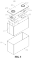
- FIG. 2 is a schematic structural diagram of battery 100 provided by some embodiments of the present application.
- Battery 100 includes box body 10 and battery cell 20, and box body 10 is configured to accommodate battery cell 20.
- box body 10 is a component for accommodating battery cell 20, box body 10 provides a receiving space for battery cell 20, and box body 10 may have various structures.
- box body 10 may include first part 11 and second part 12, and first part 11 and second part 12 cover each other to define a receiving space for accommodating battery cell 20.
- First part 11 and second part 12 may have various shapes, such as a rectangular parallelepiped and a cylinder.
- First part 11 may be a hollow structure with one side open, and second part 12 may also be a hollow structure with one side open. The open side of second part 12 covers the open side of first part 11 to form box body 10 having a receiving space.
- first part 11 is a hollow structure with one side open
- second part 12 is a platelike structure
- second part 12 covers the open side of first part 11 to form box body 10 with a receiving space.
- First part 11 and second part 12 may be sealed by a sealing element, and the sealing element may be a sealing ring, a sealant, or the like.
- the battery 100 there may be one or more battery cells 20. If there are the plurality of battery cells 20, the plurality of battery cells 20 may be connected in series or in parallel or in a mixed connection.
- the mixed connection means that the plurality of battery cells 20 are connected in both series and parallel.
- a plurality of battery cells 20 may be connected in series, in parallel, or in a mixed connection to form a battery module first, and then a plurality of battery modules may be connected in series or in parallel or mixed to form a whole, which is accommodated in box body 10. It is also possible that all battery cells 20 are directly connected in series, in parallel, or in a mixed connection to form a whole, and then the whole formed by all battery cells 20 is accommodated in box body 10.
- battery 100 may further include a bus component, and the plurality of battery cells 20 may be electrically connected through the bus component, so as to realize the series or parallel or mixed connection of the plurality of battery cells 20.
- the bus component may be a metal conductor, such as copper, iron, aluminum, stainless steel, and aluminum alloy.
- Battery cell 20 includes case 21, electrode assembly 22, end cap 23, insulating member 24, and pressure relief apparatus 25.
- Case 21 is a component for accommodating electrode assembly 22, and case 21 may be a hollow structure with an opening formed at one end.
- the case 21 may be in various shapes, such as a cylinder and a cuboid.
- Case 21 may be made of various materials, such as copper, iron, aluminum, steel, and aluminum alloy.
- Electrode assemblies 22 there may be one or a plurality of electrode assemblies 22 in case 21.
- Electrode assembly 22 is a component in battery cell 20 where an electrochemical reaction occurs. Electrode assembly 22 may include a positive electrode sheet, a negative electrode sheet, and a separator. Electrode assembly 22 may be a wound structure formed by winding a positive electrode sheet, a separator, and a negative electrode sheet, or a laminated structure formed by stacking a positive electrode sheet, a separator, and a negative electrode sheet.
- the positive electrode sheet may include a positive electrode current collector and a positive active material layer coated on two opposite sides of the positive electrode current collector.
- the negative electrode sheet may include a negative electrode current collector and a negative active material layer coated on two opposite sides of the negative electrode current collector.
- Electrode assembly 22 has positive tab 221 and negative tab 222, positive tab 221 may be a part on the positive electrode sheet that is not coated with the positive active material layer, and negative tab 222 may be a part on the negative electrode sheet that is not coated with the negative active material layer.
- end cap 23 is a component that covers the opening of case 21 to isolate the internal environment of battery cell 20 from the external environment.
- end cap 23 covers the opening of case 21, and end cap 23 and case 21 together define a sealed space for accommodating electrode assembly 22, an electrolyte solution, and other components.
- the shape of end cap 23 may be adapted to the shape of case 21.
- case 21 is a rectangular parallelepiped structure
- end cap 23 is a rectangular plate-shaped structure that matches case 21.
- case 21 is a cylindrical structure
- end cap 23 is a circular plate-shaped structure that matches case 21.
- the material of end cap 23 may also be various, for example, copper, iron, aluminum, steel, aluminum alloy, and the like.
- the material of end cap 23 and the material of case 21 may be the same or different.
- An electrode terminal may be arranged on end cap 23, and the electrode terminal is used for being electrically connected to electrode assembly 22 to output electric energy of battery cell 20.
- the electrode terminal may include positive electrode terminal 231 and negative electrode terminal 232.
- Positive electrode terminal 231 is used for electrically connecting to positive tab 221, and negative electrode terminal 232 is used for electrically connecting to negative tab 222.
- Positive electrode terminal 231 and positive tab 221 may be directly connected or indirectly connected, and negative electrode terminal 232 and negative tab 222 may be directly connected or indirectly connected.
- positive electrode terminal 231 is electrically connected to positive tab 221 through one current collecting member 26, and negative electrode terminal 232 is electrically connected to negative tab 222 through another current collecting member 26.
- Insulating member 24 is a component that separates case 21 from electrode assembly 22, and insulating isolation of case 21 and electrode assembly 22 is realized by insulating member 24.
- Insulating member 24 is an insulating material, and insulating member 24 may be an insulating material such as plastic or rubber.
- insulating member 24 circumferentially clads the outer circumference of electrode assembly 22. It is understandable when there are a plurality of electrode assemblies 22, insulating member 24 circumferentially clads the entire outer circumference of the plurality of electrode assemblies 22.
- Pressure relief apparatus 25 is a component for relieving the pressure inside battery cell 20. When the pressure or temperature inside battery cell 20 reaches a threshold value, pressure relief apparatus 25 relieves the pressure inside battery cell 20. Pressure relief apparatus 25 may be a component arranged on end cap 23, or case 21 may act as pressure relief apparatus 25. The specific structure of pressure relief apparatus 25 will be described in detail below with reference to the accompanying drawings.
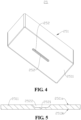
- Fig. 4 is a schematic structural diagram of pressure relief apparatus 25 provided by some embodiments of the present application
- Fig. 5 is a sectional diagram of pressure relief portion 2511 shown in Fig. 4
- pressure relief apparatus 25 includes pressure relief body 251 and a plurality of score grooves 252.
- Pressure relief body 251 includes pressure relief portion 2511 having first surface 2511a and second surface 2511b opposite to each other in a thickness direction thereof.
- the plurality of score grooves 252 are sequentially arranged on pressure relief portion 2511 in a direction from first surface 2511a to second surface 2511b, and in two adjacent score grooves 252 in the thickness direction of pressure relief portion 2511, a maximum width of score groove 252 away from first surface 2511a is less than a minimum width of score groove 252 close to first surface 2511a.
- the maximum width of score groove 252 away from first surface 2511a is smaller than the minimum width of score groove 252 close to first surface 2511a.
- the widths of the plurality of score grooves 252 gradually decrease in the direction from first surface 2511a to second surface 2511b.
- the maximum width of score groove 252 away from first surface 2511a and the minimum width of score groove 252 near first surface 2511a are the size of two adjacent score grooves 252 in the same direction.
- the maximum width of score groove 252 away from first surface 2511a does not limit that the width of score groove 252 away from first surface 2511a in two adjacent score groove 252 is gradually varied.
- the width of score groove 252 away from first surface 2511a may also be referred to as the maximum width.
- the minimum width of score groove 252 close to first surface 2511a does not limit that the width of score groove 252 close to first surface 2511a in two adjacent score grooves 252 is gradually varied.
- the width of score groove 252 close to first surface 2511a may also be referred to as the minimum width.
- Pressure relief portion 2511 may be provided with two, three, four, or more score grooves 252 sequentially in its thickness direction.
- the plurality of score grooves 252 on pressure relief portion 2511 may be formed by various methods, such as punching and milling. Taking the forming of the plurality of score grooves 252 by punching as an example, the plurality of score grooves 252 may be punched on pressure relief portion 2511 sequentially in the direction from first surface 2511a to second surface 2511b.
- first score groove 252 may be punched on first surface 2511a
- second score groove 252 may be punched on a bottom surface of first score groove 252
- third score groove 252 may be punched on a bottom surface of second score groove 252.
- First surface 2511a and second surface 2511b of pressure relief portion 2511 are the two opposite surfaces of pressure relief portion 2511 in its thickness direction, and a distance between first surface 2511a and second surface 2511b is the thickness of pressure relief portion 2511.
- Pressure relief body 251 may be a component mounted on end cap 23, for example, pressure relief body 251 is a rupture disk mounted on end cap 23. Pressure relief body 251 may also be case 21 for accommodating electrode assembly 22. A part of pressure relief body 251 may be pressure relief portion 2511, or the entire pressure relief body 251 may be pressure relief portion 2511. For example, pressure relief body 251 is a rupture disk installed on end cap 23, and pressure relief body 251 may be pressure relief portion 2511 as a whole. For another example, pressure relief body 251 is case 21 for accommodating electrode assembly 22, and pressure relief portion 2511 may be a wall or a part of a wall of case 21.
- pressure relief apparatus 25 since pressure relief portion 2511 is provided with a plurality of score grooves 252, the plurality of score grooves 252 are sequentially arranged on pressure relief portion 2511 in the direction from first surface 2511a to second surface 2511b of pressure relief portion 2511, and in two adjacent score grooves 252 in the thickness direction of pressure relief portion 2511, a maximum width of score groove 252 away from first surface 2511a is smaller than a minimum width of score groove 252 close to first surface 2511a.
- Pressure relief apparatus 25 of this structure adopts a multi-level score groove 252 structure, which can reduce a forming force received by pressure relief portion 2511 during forming of each level of score groove 252, and reduce the risk of generating cracks in pressure relief portion 2511. Pressure relief apparatus 25 is less likely to fail due to cracks in pressure relief portion 2511 at the position where score grooves 252 are provided, thereby improving the long-term reliability of pressure relief apparatus 25.
- score grooves 252 may be formed pole by pole on pressure relief portion 2511 in the direction from first surface 2511a to second surface 2511b, and the forming depth of each pole of score groove 252 is relatively shallow, so that pressure relief portion 2511 receives a small forming force, which not only reduces the risk of generating cracks in pressure relief portion 2511, but also improves the flatness of first surface 2511a.
- widths of the plurality of score grooves 252 gradually increase in the direction from second surface 2511b to first surface 2511a, and therefore, pressure relief portion 2511 may form large cracks after ruptured at the position of score grooves 252, thereby having a good pressure relief effect.
- the plurality of score grooves 252 include first score groove 2521 and second score groove 2522 extending in the same direction, and first score groove 2521 is arranged on a bottom surface of second score groove 2522.
- the plurality of score grooves 252 include first score groove 2521 and second score groove 2522. In other words, among the plurality of score grooves 252, one score groove 252 is first score groove 2521, and another score groove 252 is second score groove 2522. Of course, there may be only two score grooves 252 in the plurality of score grooves 252, and two score grooves 252 are first score groove 2521 and second score groove 2522, respectively.
- first score groove 2521 and second score groove 2522 are the same, that is, a length direction of first score groove 2521 is consistent with a length direction of second score groove 2522.
- a bottom surface of second score groove 2522 refers to a surface closest to second surface 2511b among groove wall surfaces of second score groove 2522, that is, a surface connected to a groove side surface of second score groove 2522.
- First score groove 2521 is arranged on the bottom surface of second score groove 2522, and it is understandable that in the thickness direction of pressure relief portion 2511, first score groove 2521 is closer to second surface 2511b than second score groove 2522.
- First score groove 2521 is recessed from the bottom surface of second score groove 2522 in a direction close to second surface 2511b.
- the bottom surface of second score groove 2522 may be provided with one first score groove 2521, or may be provided with a plurality of first score grooves 2521.
- one first score groove 2521 is arranged on the bottom surface of second score groove 2522, that is, one second score groove 2522 is correspondingly provided with one first score groove 2521.
- first score groove 2521 may be arranged on the bottom surface of second score groove 2522 and located at a middle position of second score groove 2522 in a width direction.
- second score groove 2522 is arranged on first surface 2511a, that is, second score groove 2522 is recessed from first surface 2511a to the direction close to second surface 2511b.
- the distance between the two opposite groove side surfaces of second score groove 2522 in the width direction thereof gradually decreases in the direction from first surface 2511a to second surface 2511b, that is, the width of second score groove 2522 gradually decreases in the direction from first surface 2511a to second surface 2511b.
- the two opposite groove side surfaces of second score groove 2522 in the width direction thereof may be inclined surfaces.
- first score groove 2521 in the width direction thereof gradually decreases in the direction from first surface 2511a to second surface 2511b, that is, the width of first score groove 2521 gradually decreases in the direction from first surface 2511a to second surface 2511b.
- the two opposite groove side surfaces of first score groove 2521 in the width direction thereof may also be inclined surfaces.
- first score groove 2521 is consistent with the extension direction of second score groove 2522, and first score groove 2521 is arranged on the bottom surface of second score groove 2522. Therefore, on the one hand, the structure facilitates formation of first score groove 2521 and ensures the length of first score groove 2521, and on the other hand, it can be ensured that the maximum width of first score groove 2521 is smaller than the minimum width of second score groove 2522.
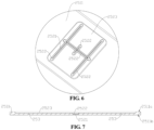
- Fig. 6 is a partial diagram of pressure relief apparatus 25 according to some other embodiments of the present application
- Fig. 7 is a sectional diagram of pressure relief portion 2511 shown in Fig. 6
- the plurality of score grooves 252 further include third score groove 2523, third score groove 2523 is arranged on first surface 2511 a, and second score grooves 2522 is arranged on a bottom surface of third score grooves 2523.
- the plurality of score grooves 252 further include third score groove 2523. It is understandable that the plurality of score grooves 252 only include first score grooves 2521, second score grooves 2522, and third score groove 2523, or may include another score groove 252 in addition to first score groove 2521, second score groove 2522, and third score groove 2523. For example, score groove 252 is further arranged on the bottom surface of first score groove 2521.
- Third score groove 2523 is arranged first surface 2511a, that is, second score groove 2522 is recessed from first surface 2511a to the direction close to second surface 2511b. Third score groove 2523 is score groove 252 closest to first surface 2511a.
- the bottom surface of third score groove 2523 refers to a surface closest to second surface 2511b among groove wall surfaces of third score groove 2523, that is, a surface connecting with a groove side surface of third score groove 2523.
- Second score groove 2522 is arranged on the bottom surface of third score groove 2523.
- second score groove 2522 is closer to second surface 2511b than third score groove 2523, second score groove 2522 is recessed from the bottom surface of third score groove 2523 in the direction close to second surface 2511b.
- the bottom surface of third score groove 2523 may be provided with one second score groove 2522, or even a plurality of second score grooves 2522.
- the plurality of score grooves 252 further include third score groove 2523 arranged on first surface 2511a, and second score groove 2522 is arranged on the bottom surface of third score groove 2523.
- pressure relief portion 2511 is provided with three levels of score grooves 252 to ensure that the forming force received by pressure relief portion 2511 will not be too large when forming each level of score groove 252, thereby reducing the risk of generating cracks in pressure relief portion 2511.
- third score groove 2523 is provided with a plurality of second score grooves 2522.
- third score groove 2523 may be various, for example, third score groove 2523 is a circular groove, a rectangular groove, and the like.
- third score groove 2523 is a rectangular groove.
- the plurality of second score grooves 2522 arranged on the bottom surface of third score groove 2523 may be arranged in various manners, for example, the plurality of second score grooves 2522 are arranged in parallel. For another example, as shown in Fig. 6 , the plurality of second score grooves 2522 form an approximately "H"-shaped structure.
- third score groove 2523 is provided with a plurality of second score grooves 2522, so that pressure relief portion 2511 may be ruptured at the position of each second score groove 2522 to achieve pressure relief, which has a better pressure relief effect and increases the pressure relief rate.
- one third score groove 2523 corresponds to a plurality of second score grooves 2522, and therefore, the forming process can be simplified and the forming cost can be reduced.
- FIG. 8 is a positional relationship diagram of first score groove 2521, second score groove 2522, and third score groove 2523 shown in Fig. 6 .
- a plurality of second score grooves 2522 include first groove section 2522a, second groove section 2522b, and third groove section 2522c, first groove section 2522a and second groove section 2522b are arranged at an interval, and first groove section 2522a and second groove section 2522b both intersect with third groove section 2522c.
- Pressure relief portion 2511 includes opening region 2511c jointly defined by first groove section 2522a, second groove section 2522b, and third groove section 2522c. Opening region 2511c is configured to be open with first groove section 2522a, second groove section 2522b, and third groove section 2522c as boundaries.
- the plurality of second score grooves 2522 include first groove section 2522a, second groove section 2522b, and third groove section 2522c.
- the first second score groove 2522 is first groove section 2522a
- the next second score groove 2522 is second groove section 2522b
- the further second score groove 2522 is third groove section 2522c.
- Opening region 2511c is a region of pressure relief portion 2511 jointly defined by first groove section 2522a, second groove section 2522b, and third groove section 2522c. There may be one or two opening regions 2511c defined by first groove section 2522a, second groove section 2522b, and third groove section 2522c.
- first groove section 2522a, second groove section 2522b, and third groove section 2522c form an approximately "open rectangular"-shaped structure, and there is one opening region 2511c.
- first groove section 2522a, second groove section 2522b and, third groove section 2522c form an approximately "H"-shaped structure, and there are two open regions 2511c.
- Opening region 2511c is the region where pressure relief portion 2511 relieves the pressure.
- the part of pressure relief portion 2511 in opening region 2511c will be open with the first groove section 2522a, second groove section 2522b, and third groove section 2522c as boundaries to achieve pressure relief.
- the plurality of second score grooves 2522 are arranged on the bottom surface of third score grooves 2523, and first groove section 2522a, second groove section 2522b, and third groove section 2522c are all arranged on the bottom surface of third score groove 2523; therefore, opening region 2511c is located in a range of third score groove 2523, and third score groove 2523 can provide an escape space in a process of the part of pressure relief portion 2511 located in opening region 2511c opening with first groove section 2522a, second groove section 2522b, and third groove section 2522c as boundaries.
- first groove section 2522a and second groove section 2522b are arranged at an interval
- second groove section 2522b and second groove section 2522b both intersect with third groove section 2522c
- first groove section 2522a, second groove section 2522b, and third groove section 2522c jointly define opening region 2511c.
- This structure enables pressure relief portion 2511 to open the part located in opening region 2511c to relieve the pressure after pressure relief portion 2511 is ruptured in positions of first groove section 2522a, second groove section 2522b, and second groove section 2522b, which increases the pressure relieve area of pressure relief portion 2511 and improves the pressure relieve rate of pressure relief portion 2511.
- the plurality of second score grooves 2522 further include fourth groove section 2522d, and in an extension direction of third groove section 2522c, fourth groove section 2522d is located between first groove section 2522a and second groove section 2522b, and fourth groove section 2522d intersects with third groove section 2522c.
- the plurality of second score grooves 2522 include fourth groove section 2522d, and it is understandable that the plurality of second score grooves 2522 include only first groove section 2522a, second groove section 2522b, third groove section 2522c, and fourth groove section 2522d, or may also include another groove section in addition to first groove section 2522a, second groove section 2522b, third groove section 2522c, and fourth groove section 2522d.
- fourth groove section 2522d may be parallel to first groove section 2522a and second groove section 2522b, and perpendicular to third groove section 2522c.
- fourth groove section 2522d between first groove section 2522a and second groove section 2522b intersects with third groove section 2522c.
- Pressure relief portion 2511 has a more concentrated stress at the intersection of third groove section 2522c and fourth groove section 2522d and is easier to rupture, so that pressure relief portion 2511 ruptures along third groove section 2522c from the intersection of third groove section 2522c and fourth groove section 2522d during the pressure relief process, and after third groove section 2522c is ruptured, and ruptures along first groove section 2522a and second groove section 2522b, thereby achieving rapid pressure relief.
- the depth of first groove section 2522a is equal to the depth of second groove section 2522b
- the depth of third groove section 2522c is equal to the depth of fourth groove section 2522d
- the depth of first groove section 2522a is less than the depth of third groove section 2522c, so that pressure relief portion 2511 is more likely to rupture along third groove section 2522c from the intersection of third groove section 2522c and fourth groove section 2522d during the pressure relief.
- the depth of first groove section 2522a, the depth of second groove section 2522b, and the depth of third groove section 2522c are all smaller than the depth of fourth groove section 2522d, which may also ensure that the pressure portion is more likely to rupture along third groove section 2522c from the intersection of third groove section 2522c and fourth groove section 2522d.
- a distance from the intersection of fourth groove section 2522d and third groove section 2522c to first groove section 2522a is equal to a distance from the intersection of fourth groove section 2522d and third groove section 2522c to second groove section 2522b.
- the distance from the intersection of fourth groove section 2522d and third groove section 2522c to first groove section 2522a is the length of the part of third groove section 2522c between fourth groove section 2522d and first groove section 2522a.
- the distance from the intersection of fourth groove section 2522d and third groove section 2522c to second groove section 2522b is the length of the part of third groove section 2522c between fourth groove section 2522d and second groove section 2522b.
- the distance from the intersection of fourth groove section 2522d and third groove section 2522c to first groove section 2522a is equal to the distance from the intersection of fourth groove section 2522d and third groove section 2522c to second groove section 2522b, so that pressure relief portion 2511 can rupture along first groove section 2522a and second groove section 2522b simultaneously after being ruptured along third groove section 2522c at the intersection of fourth groove section 2522d and third groove section 2522c.
- first groove section 2522a, second groove section 2522b, and third groove section 2522c define two opening regions 2511c, and two opening regions 2511c are respectively located in both sides of third groove section 2522c.
- First groove section 2522a, second groove section 2522b, and third groove section 2522c together define two opening regions 2511c, and first groove section 2522a, second groove section 2522b, and third groove section 2522c may constitute an approximately "H"-shaped structure.
- Two opening regions 2511c are located on both sides of third groove section 2522c, respectively, so that two opening regions 2511c are bounded by third groove section 2522c. After pressure relief portion 2511 ruptures at the position of third groove section 2522c, two opening regions 2511c will be open in a split form along first groove section 2522a and second groove section 2522b, for achieving pressure relief.
- fourth groove section 2522d is included in the plurality of second score grooves 2522, first groove section 2522a, second groove section 2522b, and third groove section 2522c can define two opening regions 2511c.
- first groove section 2522a, second groove section 2522b, and third groove section 2522c define two opening regions 2511c, and two opening regions 2511c are located on both sides of third groove section 2522c, respectively; therefore, during the pressure relief of pressure relief portion 2511, the parts of pressure relief portion 2511 in the two pressure relief regions can be opened in a split manner for pressure relief, which can effectively improve the pressure relief rate of pressure relief portion 2511.
- second surface 2511b is provided with notch groove 253 that is at least partially located in opening region 2511c, and in the extension direction of first groove section 2522a, there is a distance from notch groove 253 to third groove section 2522c.
- Second surface 2511b is provided with notch groove 253 that is at least partially located in opening region 2511c. It is understandable that notch groove 253 is recessed from second surface 2511b in a direction facing first surface 2511a, and notch groove 253 is at least partially located in opening region 2511c. Of course, notch groove 253 may be completely located in opening region 2511c, or notch groove 253 may be partially located in opening region 2511c.
- Notch groove 253 may extend in the extension direction of third groove section 2522c, so that notch groove 253 is parallel to third groove section 2522c.
- first surface 2511a may be correspondingly provided with one notch groove 253.
- first groove section 2522a, second groove section 2522b, and third groove section 2522c jointly define two opening regions 2511c
- first surface 2511a may be correspondingly provided with two notch grooves 253, one opening region 2511c being correspondingly provided with one notch groove 253.
- notch groove 253 there is a distance from notch groove 253 to third groove section 2522c in the extension direction of first groove section 2522a, and at least a part of notch groove 253 is located in opening region 2511c, so that during the pressure relief of pressure relief portion 2511, a part of pressure relief portion 2511 located in opening region 2511c may be turned over with the position of pressure relief portion 2511 located in notch groove 253 as an axis, and is easier to open for pressure relief.
- a distance between first surface 2511a and second surface 2511b is H0
- a distance from the bottom surface of score groove 252 closest to second surface 2511b to second surface 2511b is H1
- H0 and H1 meet a relational expression: H1/ H0 ⁇ 0.2.
- first surface 2511a and second surface 2511b The distance between first surface 2511a and second surface 2511b is the thickness of pressure relief portion 2511.
- the distance from the bottom surface of score groove 252 closest to second surface 2511b to second surface 2511b is the thickness of the part between the bottom surface of score groove 252 closest to second surface 2511b and second surface 2511b.
- first score groove 2521 is score groove 252 closest to second surface 2511b.
- a ratio of the distance from the bottom surface of score groove 252 closest to second surface 2511b to second surface 2511b to the distance from first surface 2511a to second surface 2511b is less than 0.2, so that the thickness of the part between the bottom surface of score groove 252 of the second surface 2511b and second surface 2511b accounts for a small proportion of the total thickness of pressure relief portion 2511, so that the part between the bottom surface of score groove 252 closest to second surface 2511b and second surface 2511b can be ruptured normally to achieve pressure relief.
- the distance from the bottom surface of score groove 252 closest to second surface 2511b to second surface 2511b is H1, and H1 meets a relational expression H1 ⁇ 0.5mm.
- the distance from the bottom surface of score groove 252 closest to second surface 2511b to second surface 2511b is less than 0.5 mm, so that the thickness of the part between the bottom surface of score groove 252 closest to second surface 2511b and second surface 2511b is small, and is easy to rupture for pressure relief.
- the depth of score groove 252 arranged on first surface 2511a is H2, and H2 meets a relational expression H2 ⁇ 1 mm.
- the depth of score groove 252 arranged on first surface 2511a is the distance from the bottom surface of score groove 252 arranged on first surface 2511a to first surface 2511a.
- third score groove 2523 is score groove 252 arranged on first surface 2511a.
- the depth of score groove 252 arranged on first surface 2511a is less than 1 mm, so that the depth of score groove 252 on the outermost side of pressure relief portion 2511 is small, thereby reducing the forming force received by pressure relief portion 2511 during the forming of score groove 252, and reducing the risk of generating cracks in pressure relief portion 2511.
- the depth of score groove 252 between score groove 252 closest to second surface 2511b and score groove 252 arranged on first surface 2511a is H3, and H3 meets a relational expression H3 ⁇ 1.5 mm.
- the plurality of score grooves 252 include at least three score grooves 252. Taking the plurality of score grooves 252 including only first score groove 2521, second score groove 2522, and third score groove 2523 as an embodiment, score groove 252 closest to second surface 2511b is first score groove 2521, score groove 252 arranged on first surface 2511a is third score groove 2523, and score groove 252 between score groove 252 closest to second surface 2511b and score groove 252 arranged on first surface 2511a is second score groove 2522.
- the depth of score groove 252 between score groove 252 closest to second surface 2511b and score groove 252 arranged on first surface 2511a is less than 1.5 mm, so that on pressure relief portion 2511, the depth of score groove 252 except score groove 252 closest to second surface 2511b and score groove 252 arranged on first surface 2511a is small, which reduces the forming force received by pressure relief portion 2511 during the forming, and reduces the risk of generating cracks in pressure relief portion 2511.
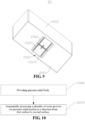
- FIG. 9 is a schematic structural diagram of pressure relief apparatus 25 according to some other embodiments of the present application.
- An accommodating space is formed inside pressure relief body 251
- pressure relief body 251 has a plurality of walls defining the accommodating space, the accommodating space is used for accommodating electrode assembly 22, and a pressure relief portion 2511 is formed on one wall of the plurality of walls.
- One wall of the plurality of walls being provided with pressure relief portion 2511 may be that a part of one wall is pressure relief portion 2511, or the entire wall is pressure relief portion 2511.
- First surface 2511a of pressure relief portion 2511 may be an outer surface of the wall or an inner surface of the wall.
- the outer surface of the wall is a surface of the wall away from electrode assembly 22, and the inner surface of a surface of the wall facing electrode assembly 22.
- Pressure relief body 251 may have various shapes, such as a rectangular parallelepiped and a cylinder.
- a plurality of walls of pressure relief body 251 define an accommodating cavity used for accommodating electrode assembly 22, and pressure relief portion 2511 is formed in one of the plurality of walls, so that pressure relief apparatus 25 has both the accommodating function for accommodating electrode assembly 22 and the pressure relief function.
- the plurality of walls of pressure relief body 251 include peripheral wall 2512 and bottom wall 2513, peripheral wall 2512 is arranged around an edge of bottom wall 2513, and peripheral wall 2512 and bottom wall 2513 jointly define the accommodating space.
- Pressure relief portion 2511 is formed on bottom wall 2513.
- Peripheral wall 2512 is arranged around the edge bottom wall 2513, so that pressure relief body 251 forms an opening at an end opposite to bottom wall 2513, and end cap 23 is used for covering the opening.
- pressure relief body 251 may have two walls, one of the walls is bottom wall 2513 and the other wall is peripheral wall 2512. As shown in Fig. 9 , in the embodiment where pressure relief body 251 is a rectangular parallelepiped, pressure relief body 251 may have five walls, that is, one bottom wall 2513 and four side walls, and the four side walls are connected end to end to form peripheral wall 2512.
- peripheral wall 2512 and bottom wall 2513 are of an integrally molded structure.
- Peripheral wall 2512 and bottom wall 2513 are of an integrally molded structure, that is to say, peripheral wall 2512 and bottom wall 2513 are formed into one piece.
- bottom wall 2513 is provided with pressure relief portion 2511, and peripheral wall 2512 and bottom wall 2513 are of an integrally molded structure, so that peripheral wall 2512 and bottom wall 2513 with a pressure relief function have good firmness.
- Such integrated design simplifies the forming process and reduces production costs.
- first surface 2511a is the outer surface of bottom wall 2513, that is, the plurality of score grooves 252 on pressure relief portion 2511 are arranged sequentially from the outer surface of bottom wall 2513 to the inner surface of bottom wall 2513, which is convenient to process score grooves 252 on pressure relief body 251.
- battery cell 20 is provided in an embodiment of the present application, and includes pressure relief apparatus 25 according to any one of the above embodiments.
- battery 100 includes box body 10 and battery cells 20 according to any one of the above embodiments, and case 10 is configured to accommodate battery cell 20.
- an electrical device includes battery 100 according to any one of the above embodiments.
- the electrical device may be any of the above device using battery 100.
- Case 21 is further provided in an embodiment of the present application.
- Case 21 includes a plurality of walls, and the plurality of walls jointly define an accommodating space for accommodating electrode assembly 22, at least one wall is provided with a plurality of score grooves 252, and the wall has first surface 2511a and second surface 2511b opposite to each other in a thickness direction thereof.
- the plurality of score grooves 252 are sequentially arranged on the wall in a direction from first surface 2511a to second surface 2511b. In two adjacent score grooves 252 in the thickness direction of the wall, a maximum width of score groove 252 away from first surface 2511a is smaller than a minimum width of score groove 252 close to first surface 2511a.
- Case 21 of this structure integrates the pressure relief function and the accommodating function, and adopts multi-level score groove 252 structure, which can reduce the forming force received by case 21 when each level of score groove 252 is formed, thereby reducing the risk of generating cracks on case 21, and improving the long-term reliability of pressure relief apparatus 25.
- a manufacture method for pressure relief apparatus 25 is provided in an embodiment of the present application. Referring to Fig. 10 , which is a flow chart of the manufacture method for pressure relief apparatus 25 provided by some embodiments of the present application. The method includes the following steps:
- pressure relief body 251 Providing pressure relief body 251, pressure relief body 251 including pressure relief portion 2511, and pressure relief portion 2511 having first surface 2511a and second surface 2511b opposite to each other in a thickness direction thereof; and
- S200 Sequentially processing a plurality of score grooves 252 on pressure relief portion 2511 in a direction from first surface 2511a to second surface 2511b, wherein in two adjacent score grooves 252 in the thickness direction, a maximum width of score groove 252 away from first surface 2511a is less than a minimum width of score groove 252 close to first surface 2511a.
- sequentially processing a plurality of score grooves 252 on pressure relief portion 2511 in a direction from first surface 2511a to second surface 2511b includes: sequentially punching a plurality of score grooves 252 on pressure relief portion 2511 in the direction from first surface 2511a to second surface 2511b.
- a plurality of score grooves 252 are sequentially formed on pressure relief portion 2511 in the direction from first surface 2511a to second surface 2511b by punching.
- the forming process is simple, which can reduce the punching force received by pressure relief portion 2511 during punching of each level of score groove 252, and reducing the risk of generating cracks in pressure relief portion 2511.
- pressure relief apparatus 25 for the relevant structure of pressure relief apparatus 25 manufactured by the manufacturing method according to the above embodiments, reference can be made to pressure relief apparatus 25 according to the foregoing embodiments, which will not be repeated here.
- manufacturing device 2000 for pressure relief apparatus 25 is provided in an embodiment of the present application.
- Fig. 11 is a schematic block diagram of manufacturing device 2000 for pressure relief apparatus 25 provided by some embodiments of the present application.
- Manufacturing device 2000 includes first providing apparatus 2100 and processing apparatus 2200.
- First providing apparatus 2100 is configured to provide pressure relief body 251, pressure relief body 251 including pressure relief portion 2511, and pressure relief portion 2511 having first surface 2511a and second surface 2511b opposite to each other in a thickness direction thereof.
- Processing apparatus 2200 is configured to sequentially process a plurality of score grooves 252 on pressure relief portion 2511 in a direction from first surface 2511a to second surface 2511b. In two adjacent score grooves 252 in the thickness direction, a maximum width of score groove 252 far away from first surface 2511a is less than a minimum width of score groove 252 close to the first surface 2511a.
- pressure relief apparatus 25 manufactured by manufacturing device 2000 according to the above embodiment, reference can be made to pressure relief apparatus 25 according to the foregoing embodiments, which will not be repeated here.
Landscapes
- Chemical Kinetics & Catalysis (AREA)
- Electrochemistry (AREA)
- General Chemical & Material Sciences (AREA)
- Chemical & Material Sciences (AREA)
- Engineering & Computer Science (AREA)
- Aviation & Aerospace Engineering (AREA)
- General Engineering & Computer Science (AREA)
- Computer Hardware Design (AREA)
- Biophysics (AREA)
- Life Sciences & Earth Sciences (AREA)
- Mechanical Engineering (AREA)
- Sealing Battery Cases Or Jackets (AREA)
- Gas Exhaust Devices For Batteries (AREA)
- Battery Mounting, Suspending (AREA)
- Manufacturing & Machinery (AREA)
Claims (13)
- Batteriezelle (20), umfassend eine Druckentlastungsvorrichtung (25), wobeidie Druckentlastungsvorrichtung (25) einen Druckentlastungskörper (251) und eine Vielzahl von Ritzrillen (252) umfasst, wobeider Druckentlastungskörper (251) einen Druckentlastungsabschnitt (2511) umfasst, wobei der Druckentlastungsabschnitt (2511) eine erste Fläche (2511a) und eine zweite Fläche (2511b) aufweist, die in einer Dickenrichtung davon einander gegenüberliegen;ein Aufnahmeraum im Inneren des Druckentlastungskörpers (251) ausgebildet ist, der Druckentlastungskörper (251) eine Vielzahl von Wänden aufweist, die den Aufnahmeraum definieren, der Aufnahmeraum dazu ausgelegt ist, eine Elektrodenanordnung (22) aufzunehmen, und eine Wand der Vielzahl von Wänden mit dem Druckentlastungsabschnitt (2511) versehen ist; die Vielzahl von Wänden eine Umfangswand (2512) und eine Bodenwand (2513) umfasst, die Umfangswand (2512) um einen Rand der Bodenwand (2513) herum angeordnet ist, die Umfangswand (2512) und die Bodenwand (2513) zusammen den Aufnahmeraum definieren, und die Bodenwand (2513) mit dem Druckentlastungsabschnitt (2511) versehen ist; die erste Fläche (2511a) eine Außenfläche der Bodenwand (2513) ist;die Vielzahl von Ritzrillen (252) sequentiell am Druckentlastungsabschnitt (2511) in einer Richtung von der ersten Fläche (2511a) zur zweiten Fläche (2511b) angeordnet sind, wobei in zwei benachbarten Ritzrillen (252) in der Dickenrichtung eine maximale Breite einer Ritzrille (252), die weiter von der ersten Fläche (2511a) entfernt ist, kleiner als eine minimale Breite einer Ritzrille (252) ist, die näher an der ersten Fläche (2511a) liegt;die Vielzahl von Ritzrillen (252) eine erste Ritzrille (2521) und eine zweite Ritzrille (2522) umfasst, die sich in der gleichen Richtung erstrecken, und die erste Ritzrille (2521) auf einer Bodenfläche der zweiten Ritzrille (2522) angeordnet ist;die Vielzahl von Ritzrillen (252) ferner eine dritte Ritzrille (2523) umfasst, die dritte Ritzrille (2523) auf der ersten Fläche (2511a) angeordnet ist, die zweite Ritzrille (2522) auf einer Bodenfläche der dritten Ritzrille (2523) angeordnet ist und die Bodenfläche der dritten Ritzrille (2523) mit einer Vielzahl der zweiten Ritzrillen (2522) versehen ist;die Vielzahl der zweiten Ritzrillen (2522) einen ersten Rillenabschnitt (2522a), einen zweiten Rillenabschnitt (2522b) und einen dritten Rillenabschnitt (2522c) umfasst, der erste Rillenabschnitt (2522a) und der zweite Rillenabschnitt (2522b) in einem Abstand angeordnet sind und sowohl der erste Rillenabschnitt (2522a) als auch der zweite Rillenabschnitt (2522b) sich mit dem dritten Rillenabschnitt (2522c) kreuzen; undder Druckentlastungsabschnitt (2511) einen Öffnungsbereich (2511c) umfasst, der gemeinsam durch den ersten Rillenabschnitt (2522a), den zweiten Rillenabschnitt (2522b) und den dritten Rillenabschnitt (2522c) definiert wird, und der Öffnungsbereich (2511c) dazu ausgelegt ist, sich mit dem ersten Rillenabschnitt (2522a), dem zweiten Rillenabschnitt (2522b) und dem dritten Rillenabschnitt (2522c) als Grenzen zu öffnen;dadurch gekennzeichnet, dassdie Vielzahl der zweiten Ritzrillen (2522) ferner einen vierten Rillenabschnitt (2522d) umfasst, und in einer Erstreckungsrichtung des dritten Rillenabschnitts (2522c) sich der vierte Rillenabschnitt (2522d) zwischen dem ersten Rillenabschnitt (2522a) und dem zweiten Rillenabschnitt (2522b) befindet, und der vierte Rillenabschnitt (2522d) sich mit dem dritten Rillenabschnitt (2522c) kreuzt.
- Batteriezelle (20) nach Anspruch 1, wobei in der Erstreckungsrichtung des dritten Rillenabschnitts (2522c) ein Abstand von der Kreuzung des vierten Rillenabschnitts (2522d) und des dritten Rillenabschnitts (2522c) zum ersten Rillenabschnitt (2522a) gleich einem Abstand von der Kreuzung des vierten Rillenabschnitts (2522d) und des dritten Rillenabschnitts (2522c) zum zweiten Rillenabschnitt (2522b) ist.
- Batteriezelle (20) nach Anspruch 1 oder 2, wobei der erste Rillenabschnitt (2522a), der zweite Rillenabschnitt (2522b) und der dritte Rillenabschnitt (2522c) zwei Öffnungsbereiche (2511c) definieren, und die zwei Öffnungsbereiche (2511c) auf zwei Seiten des dritten Rillenabschnitts (2522c) angeordnet sind.
- Batteriezelle (20) nach einem der Ansprüche 1 bis 3, wobei die zweite Fläche (2511b) mit einer Kerbnut (253) versehen ist, die sich im Öffnungsbereich (2511c) befindet, und in der Erstreckungsrichtung des ersten Rillenabschnitts (2522a) ein Abstand zwischen der Kerbnut (253) und dem dritten Rillenabschnitt (2522c) besteht.
- Batteriezelle (20) nach einem der Ansprüche 1 bis 4, wobei ein Abstand zwischen der ersten Fläche (2511a) und der zweiten Fläche (2511b) H0 ist und ein Abstand von einer Bodenfläche der Ritzrille (252), die der zweiten Fläche (2511b) am nächsten liegt, zur zweiten Fläche (2511b) H1 ist, und H0 und H1 einen Beziehungsausdruck von H1/H0<0,2 erfüllen.
- Batteriezelle (20) nach einem der Ansprüche 1 bis 5, wobei der Abstand von der Bodenfläche der Ritzrille (252), die der zweiten Fläche (2511b) am nächsten liegt, zur zweiten Fläche (2511b) H1 ist, und H1 einen Beziehungsausdruck von H1<0,5 mm erfüllt.
- Batteriezelle (20) nach einem der Ansprüche 1 bis 6, wobei die Tiefe der auf der ersten Fläche (2511a) angeordneten Ritzrille (252) H2 ist, und H2 einen Beziehungsausdruck von H2<1 mm erfüllt.
- Batteriezelle (20) nach einem der Ansprüche 1 bis 7, wobei die Tiefe einer Ritzrille (252) zwischen der Ritzrille (252), die der zweiten Fläche (2511b) am nächsten liegt, und der auf der ersten Fläche (2511a) angeordneten Ritzrille (252) H3 ist, und H3 den Beziehungsausdruck H3<1,5 mm erfüllt.
- Batteriezelle (20) nach einem der Ansprüche 1 bis 8, wobei die Umfangswand (2512) und die Bodenwand (2513) eine einstückig geformte Struktur aufweisen.
- Batterie (100), umfassend:die Batteriezelle (20) nach einem der Ansprüche 1 bis 9; undeinen Gehäusekörper (10), der dazu ausgelegt ist, die Batteriezelle (20) aufzunehmen.
- Elektrische Einrichtung, umfassend die Batterie (100) nach Anspruch 10.
- Herstellungsverfahren für die Batteriezelle (20) nach einem der Ansprüche 1 bis 9, wobei das Verfahren umfasst:Bereitstellen des Druckentlastungskörpers (251); undsequentielles Bearbeiten der Vielzahl von Ritzrillen (252) auf dem Druckentlastungsabschnitt (2511) in einer Richtung von der ersten Fläche (2511a) zur zweiten Fläche (2511b), umfassend: sequentielles Stanzen der Vielzahl von Ritzrillen (252) auf dem Druckentlastungsabschnitt (2511) in der Richtung von der ersten Fläche (2511a) zur zweiten Fläche (2511b).
- Herstellungsvorrichtung (2000) für die Batteriezelle (20) nach einem der Ansprüche 1 bis 9, umfassend:eine erste Bereitstellungsvorrichtung (2100), die dazu ausgelegt ist, den Druckentlastungskörper (251) bereitzustellen; undeine Bearbeitungsvorrichtung (2200), die dazu ausgelegt ist, die Vielzahl von Ritzrillen (252) sequentiell auf dem Druckentlastungsabschnitt (2511) in einer Richtung von der ersten Fläche (2511a) zur zweiten Fläche (2511b) zu bearbeiten.
Applications Claiming Priority (1)
| Application Number | Priority Date | Filing Date | Title |
|---|---|---|---|
| PCT/CN2021/115766 WO2023028864A1 (zh) | 2021-08-31 | 2021-08-31 | 泄压装置、电池单体、电池及用电设备 |
Publications (3)
| Publication Number | Publication Date |
|---|---|
| EP4167368A1 EP4167368A1 (de) | 2023-04-19 |
| EP4167368A4 EP4167368A4 (de) | 2024-05-15 |
| EP4167368B1 true EP4167368B1 (de) | 2025-01-22 |
Family
ID=85029951
Family Applications (4)
| Application Number | Title | Priority Date | Filing Date |
|---|---|---|---|
| EP21948694.1A Active EP4167368B1 (de) | 2021-08-31 | 2021-08-31 | Batteriezelle, batterie, stromverbrauchsgerät, verfahren und vorrichtung zur herstellung einer batteriezelle |
| EP22863540.5A Pending EP4287380A4 (de) | 2021-08-31 | 2022-08-31 | Druckentlastungsvorrichtung, batteriezelle, batterie und stromverbrauchsvorrichtung |
| EP22863534.8A Pending EP4340112A4 (de) | 2021-08-31 | 2022-08-31 | Druckentlastungsvorrichtung, batteriezelle, batterie und elektrische vorrichtung |
| EP22863539.7A Pending EP4239777A4 (de) | 2021-08-31 | 2022-08-31 | Druckentlastungsvorrichtung, batteriezelle, batterie und elektrische vorrichtung |
Family Applications After (3)
| Application Number | Title | Priority Date | Filing Date |
|---|---|---|---|
| EP22863540.5A Pending EP4287380A4 (de) | 2021-08-31 | 2022-08-31 | Druckentlastungsvorrichtung, batteriezelle, batterie und stromverbrauchsvorrichtung |
| EP22863534.8A Pending EP4340112A4 (de) | 2021-08-31 | 2022-08-31 | Druckentlastungsvorrichtung, batteriezelle, batterie und elektrische vorrichtung |
| EP22863539.7A Pending EP4239777A4 (de) | 2021-08-31 | 2022-08-31 | Druckentlastungsvorrichtung, batteriezelle, batterie und elektrische vorrichtung |
Country Status (6)
| Country | Link |
|---|---|
| US (5) | US20230223644A1 (de) |
| EP (4) | EP4167368B1 (de) |
| JP (4) | JP7514380B2 (de) |
| KR (6) | KR20230035342A (de) |
| CN (7) | CN116438702B (de) |
| WO (4) | WO2023028864A1 (de) |
Families Citing this family (21)
| Publication number | Priority date | Publication date | Assignee | Title |
|---|---|---|---|---|
| EP4167368B1 (de) * | 2021-08-31 | 2025-01-22 | Contemporary Amperex Technology (Hong Kong) Limited | Batteriezelle, batterie, stromverbrauchsgerät, verfahren und vorrichtung zur herstellung einer batteriezelle |
| US20240253477A1 (en) * | 2023-01-26 | 2024-08-01 | GM Global Technology Operations LLC | Battery assemblies, vehicles, and methods with pouch-type battery cells having terminal end caps |
| CN118920004A (zh) * | 2023-05-06 | 2024-11-08 | 宁德时代新能源科技股份有限公司 | 电池单体、电池及用电装置 |
| CN116207434B (zh) * | 2023-05-06 | 2024-02-20 | 宁德时代新能源科技股份有限公司 | 泄压部件、电池单体、电池及用电装置 |
| CN116666887A (zh) * | 2023-05-31 | 2023-08-29 | 宁德时代新能源科技股份有限公司 | 电池单体、电池及用电设备 |
| CN119069942A (zh) * | 2023-05-31 | 2024-12-03 | 宁德时代新能源科技股份有限公司 | 电池单体、电池及用电设备 |
| WO2025065507A1 (zh) * | 2023-09-28 | 2025-04-03 | 宁德时代新能源科技股份有限公司 | 泄压部件、电池单体、电池及用电设备 |
| CN121039881A (zh) * | 2023-11-09 | 2025-11-28 | 宁德时代新能源科技股份有限公司 | 电池单体、电池及用电装置 |
| EP4668419A1 (de) * | 2023-11-28 | 2025-12-24 | Contemporary Amperex Technology Co., Limited | Batteriezelle, batterie und elektrische vorrichtung |
| KR20250094388A (ko) * | 2023-12-18 | 2025-06-25 | 에스케이온 주식회사 | 이차전지 |
| WO2025138229A1 (zh) * | 2023-12-29 | 2025-07-03 | 宁德时代新能源科技股份有限公司 | 电池单体、电池及用电设备 |
| CN121128006A (zh) * | 2023-12-29 | 2025-12-12 | 宁德时代新能源科技股份有限公司 | 电池单体、电池及用电设备 |
| WO2025138250A1 (zh) * | 2023-12-29 | 2025-07-03 | 宁德时代新能源科技股份有限公司 | 电池单体、电池及用电装置 |
| CN120981970A (zh) * | 2023-12-29 | 2025-11-18 | 宁德时代新能源科技股份有限公司 | 电池单体、电池及用电设备 |
| CN120981971A (zh) * | 2023-12-29 | 2025-11-18 | 宁德时代新能源科技股份有限公司 | 电池单体、电池及用电设备 |
| WO2025148033A1 (zh) * | 2024-01-12 | 2025-07-17 | 宁德时代新能源科技股份有限公司 | 电池单体、电池及用电设备 |
| CN221632797U (zh) * | 2024-05-16 | 2024-08-30 | 宁德时代新能源科技股份有限公司 | 电池单体、电池及用电设备 |
| WO2025247123A1 (zh) * | 2024-05-31 | 2025-12-04 | 宁波敏实汽车零部件技术研发有限公司 | 一种防爆结构、电池及用电设备 |
| DE102024117278A1 (de) * | 2024-06-19 | 2025-12-24 | Schaeffler Technologies AG & Co. KG | Batteriezellengehäuse mit einer Berstnut und Sollbruchstelle |
| DE102024117277A1 (de) * | 2024-06-19 | 2025-12-24 | Schaeffler Technologies AG & Co. KG | Verfahren zur Herstellung eines Batteriezellengehäuses mit Überdruckabbaumittel sowie Batteriezellengehäuse und Batteriezelle |
| WO2026007129A1 (zh) * | 2024-07-05 | 2026-01-08 | 宁德时代新能源科技股份有限公司 | 电池单体、电池及用电装置 |
Family Cites Families (42)
| Publication number | Priority date | Publication date | Assignee | Title |
|---|---|---|---|---|
| JPS61143936A (ja) * | 1984-12-17 | 1986-07-01 | Matsushita Electric Ind Co Ltd | 密閉形蓄電池 |
| JPH0348890Y2 (de) | 1985-02-28 | 1991-10-18 | ||
| JP2653832B2 (ja) * | 1988-06-07 | 1997-09-17 | 旭化成工業株式会社 | 密閉電池 |
| JP3771366B2 (ja) * | 1998-01-12 | 2006-04-26 | 三菱電線工業株式会社 | 密閉型電池 |
| JP2000182591A (ja) * | 1998-12-15 | 2000-06-30 | Japan Storage Battery Co Ltd | 電 池 |
| JP2000285892A (ja) | 1999-03-31 | 2000-10-13 | Toshiba Electronic Engineering Corp | 非水電解液二次電池 |
| JP2000348700A (ja) * | 1999-06-03 | 2000-12-15 | Alps Electric Co Ltd | 電池の安全弁 |
| US20030028399A1 (en) | 2000-09-25 | 2003-02-06 | Duane Davis | Method and system for providing interactive health care services |
| JP4219661B2 (ja) * | 2002-11-22 | 2009-02-04 | パナソニック株式会社 | 電池用封口板 |
| JP2004178909A (ja) * | 2002-11-26 | 2004-06-24 | Matsushita Electric Ind Co Ltd | 密閉式二次電池 |
| JP2005038709A (ja) | 2003-07-15 | 2005-02-10 | Hitachi Maxell Ltd | 密閉型電池 |
| JP5198723B2 (ja) * | 2005-06-13 | 2013-05-15 | 冨士発條株式会社 | 密閉型電池用封口板 |
| JP5503101B2 (ja) * | 2007-06-22 | 2014-05-28 | 株式会社神戸製鋼所 | 電池ケース |
| JP4386139B1 (ja) * | 2008-08-20 | 2009-12-16 | トヨタ自動車株式会社 | 電池 |
| JP5059033B2 (ja) | 2009-01-16 | 2012-10-24 | 東芝照明プレシジョン株式会社 | 封口体とその製造方法、電池容器ボディ、及び密閉型電池 |
| KR101106323B1 (ko) * | 2010-07-22 | 2012-01-18 | 에스비리모티브 주식회사 | 이차 전지 |
| KR101223522B1 (ko) * | 2010-08-16 | 2013-01-17 | 로베르트 보쉬 게엠베하 | 이차전지 |
| JP5592291B2 (ja) * | 2011-03-01 | 2014-09-17 | プライムアースEvエナジー株式会社 | 密閉型電池及び安全弁 |
| JP5876794B2 (ja) * | 2012-09-04 | 2016-03-02 | 小島プレス工業株式会社 | 二次電池用ケース及び二次電池 |
| JP2014102935A (ja) * | 2012-11-19 | 2014-06-05 | Toyota Industries Corp | 蓄電装置 |
| JP5542192B2 (ja) * | 2012-12-11 | 2014-07-09 | 日新製鋼株式会社 | 電池ケース用の蓋体 |
| JP6244152B2 (ja) * | 2013-09-26 | 2017-12-06 | 株式会社協豊製作所 | 密閉型電池の安全弁 |
| US20160079578A1 (en) | 2014-09-12 | 2016-03-17 | Johnson Controls Technology Company | Hinged vent for electrochemical cell system and method |
| JP6088566B2 (ja) | 2015-02-24 | 2017-03-01 | 東芝照明プレシジョン株式会社 | 封口板、封口板の製造方法、及び、密閉型電池 |
| JP6686286B2 (ja) * | 2015-03-30 | 2020-04-22 | 三洋電機株式会社 | 角形二次電池及びそれを用いた組電池 |
| WO2016203708A1 (ja) * | 2015-06-16 | 2016-12-22 | ソニー株式会社 | 電池、電池缶、電池パック、電子機器、電動車両、蓄電装置および電力システム |
| KR102629177B1 (ko) * | 2016-07-12 | 2024-01-26 | 삼성에스디아이 주식회사 | 이차 전지 |
| CN110720149B (zh) * | 2017-06-15 | 2022-05-27 | 株式会社村田制作所 | 二次电池、电池包、电动车辆、电力储存系统、电动工具以及电子设备 |
| CN207134411U (zh) * | 2017-08-16 | 2018-03-23 | 深圳市瑞德丰精密制造有限公司 | 爆破片 |
| JP7025861B2 (ja) * | 2017-08-22 | 2022-02-25 | 大和製罐株式会社 | 封口板 |
| US20200328399A1 (en) * | 2017-12-13 | 2020-10-15 | Byd Company Limited | Battery cover plate assembly, cell, battery module, power battery, and electric vehicle |
| DE112019002091T5 (de) * | 2019-04-02 | 2021-02-25 | Changzhou Microbat Technology Co. Ltd. | Explosionsgeschütztes gehäuse für eine energiespeichervorrichtung sowie eine energiespeichervorrichtung |
| CN111446388B (zh) * | 2020-04-20 | 2025-02-11 | 欣旺达动力科技股份有限公司 | 一种电池顶盖组件及单体电池 |
| CN212136523U (zh) * | 2020-05-25 | 2020-12-11 | 上海比耐信息科技有限公司 | 一种高安全的大容量电池 |
| CN212461953U (zh) * | 2020-07-08 | 2021-02-02 | 惠州比亚迪电池有限公司 | 防爆片、防爆阀和电池 |
| CN213340640U (zh) * | 2020-11-09 | 2021-06-01 | 宁德时代新能源科技股份有限公司 | 端盖组件、电池单体、电池以及用电装置 |
| CN213546511U (zh) * | 2020-11-17 | 2021-06-25 | 上海兰钧新能源科技有限公司 | 一种电池防爆阀、电池盖板及电池 |
| CN215989102U (zh) * | 2021-08-31 | 2022-03-08 | 宁德时代新能源科技股份有限公司 | 泄压装置、电池单体、电池及用电设备 |
| CN215989101U (zh) * | 2021-08-31 | 2022-03-08 | 宁德时代新能源科技股份有限公司 | 泄压装置、电池单体、电池及用电设备 |
| EP4167368B1 (de) * | 2021-08-31 | 2025-01-22 | Contemporary Amperex Technology (Hong Kong) Limited | Batteriezelle, batterie, stromverbrauchsgerät, verfahren und vorrichtung zur herstellung einer batteriezelle |
| CN114447514A (zh) * | 2021-09-29 | 2022-05-06 | 上海砚泽智能科技有限公司 | 一种新能源防爆电池壳及其生产工艺 |
| CN217182358U (zh) * | 2022-03-14 | 2022-08-12 | 宁德时代新能源科技股份有限公司 | 壳体、电池单体、电池及用电设备 |
-
2021
- 2021-08-31 EP EP21948694.1A patent/EP4167368B1/de active Active
- 2021-08-31 JP JP2023502626A patent/JP7514380B2/ja active Active
- 2021-08-31 KR KR1020237003696A patent/KR20230035342A/ko not_active Ceased
- 2021-08-31 CN CN202180066181.6A patent/CN116438702B/zh active Active
- 2021-08-31 WO PCT/CN2021/115766 patent/WO2023028864A1/zh not_active Ceased
-
2022
- 2022-08-31 CN CN202222326423.5U patent/CN218769952U/zh active Active
- 2022-08-31 KR KR1020237015526A patent/KR102861520B1/ko active Active
- 2022-08-31 CN CN202222314407.4U patent/CN218414925U/zh active Active
- 2022-08-31 CN CN202280010076.5A patent/CN116783763A/zh active Pending
- 2022-08-31 EP EP22863540.5A patent/EP4287380A4/de active Pending
- 2022-08-31 WO PCT/CN2022/116298 patent/WO2023030404A1/zh not_active Ceased
- 2022-08-31 CN CN202280005459.3A patent/CN116075964B/zh active Active
- 2022-08-31 WO PCT/CN2022/116275 patent/WO2023030399A1/zh not_active Ceased
- 2022-08-31 WO PCT/CN2022/116299 patent/WO2023030405A1/zh not_active Ceased
- 2022-08-31 JP JP2023530006A patent/JP7731986B2/ja active Active
- 2022-08-31 KR KR1020257037094A patent/KR20250164858A/ko active Pending
- 2022-08-31 EP EP22863534.8A patent/EP4340112A4/de active Pending
- 2022-08-31 KR KR1020237016596A patent/KR102885459B1/ko active Active
- 2022-08-31 CN CN202222314334.9U patent/CN218414924U/zh active Active
- 2022-08-31 JP JP2023530008A patent/JP7592163B2/ja active Active
- 2022-08-31 EP EP22863539.7A patent/EP4239777A4/de active Pending
- 2022-08-31 KR KR1020237016558A patent/KR102885458B1/ko active Active
- 2022-08-31 JP JP2023528257A patent/JP7607126B2/ja active Active
- 2022-08-31 KR KR1020257037095A patent/KR20250161054A/ko active Pending
- 2022-08-31 CN CN202280009602.6A patent/CN116711134A/zh active Pending
-
2023
- 2023-03-21 US US18/187,207 patent/US20230223644A1/en active Pending
- 2023-06-12 US US18/333,167 patent/US20230327275A1/en active Pending
- 2023-09-11 US US18/464,845 patent/US12451559B2/en active Active
-
2024
- 2024-01-16 US US18/413,080 patent/US20240154240A1/en active Pending
-
2025
- 2025-09-29 US US19/344,047 patent/US20260031471A1/en active Pending
Also Published As
Similar Documents
| Publication | Publication Date | Title |
|---|---|---|
| EP4167368B1 (de) | Batteriezelle, batterie, stromverbrauchsgerät, verfahren und vorrichtung zur herstellung einer batteriezelle | |
| US20240079693A1 (en) | End cover assembly, battery cell, battery, and electrical apparatus | |
| CN216354620U (zh) | 电池单体、电池以及用电装置 | |
| CN216903232U (zh) | 泄压装置、电池单体、电池及用电设备 | |
| US20230155262A1 (en) | Housing, battery cell, battery and electric apparatus | |
| US12548837B2 (en) | Battery cell, manufacturing method and manufacturing system thereof, battery, and powered device | |
| CN115832603B (zh) | 外壳、电池单体、电池及用电设备 | |
| CN217158424U (zh) | 外壳、电池单体、电池及用电设备 | |
| WO2023220886A1 (zh) | 端盖、电池单体、电池及用电设备 | |
| US20230223642A1 (en) | Pressure relief apparatus, battery cell, battery, and electrical device | |
| US20240313337A1 (en) | End Cover, Battery Cell, Battery, and Electrical Device | |
| EP4391185A1 (de) | Gehäuse, batteriezelle, batterie und elektrische vorrichtung | |
| CA3183528C (en) | Pressure relief apparatus, battery cell, battery, and electrical device | |
| US20230198089A1 (en) | Pressure relief apparatus, battery cell, battery and electric apparatus |
Legal Events
| Date | Code | Title | Description |
|---|---|---|---|
| STAA | Information on the status of an ep patent application or granted ep patent |
Free format text: STATUS: UNKNOWN |
|
| STAA | Information on the status of an ep patent application or granted ep patent |
Free format text: STATUS: THE INTERNATIONAL PUBLICATION HAS BEEN MADE |
|
| PUAI | Public reference made under article 153(3) epc to a published international application that has entered the european phase |
Free format text: ORIGINAL CODE: 0009012 |
|
| STAA | Information on the status of an ep patent application or granted ep patent |
Free format text: STATUS: REQUEST FOR EXAMINATION WAS MADE |
|
| 17P | Request for examination filed |
Effective date: 20230112 |
|
| AK | Designated contracting states |
Kind code of ref document: A1 Designated state(s): AL AT BE BG CH CY CZ DE DK EE ES FI FR GB GR HR HU IE IS IT LI LT LU LV MC MK MT NL NO PL PT RO RS SE SI SK SM TR |
|
| RAP3 | Party data changed (applicant data changed or rights of an application transferred) |
Owner name: CONTEMPORARY AMPEREX TECHNOLOGY CO., LIMITED |
|
| A4 | Supplementary search report drawn up and despatched |
Effective date: 20240415 |
|
| RIC1 | Information provided on ipc code assigned before grant |
Ipc: H01M 50/103 20210101ALI20240410BHEP Ipc: H01M 50/342 20210101AFI20240410BHEP |
|
| RAP1 | Party data changed (applicant data changed or rights of an application transferred) |
Owner name: CONTEMPORARY AMPEREX TECHNOLOGY(HONG KONG) LIMITED |
|
| GRAP | Despatch of communication of intention to grant a patent |
Free format text: ORIGINAL CODE: EPIDOSNIGR1 |
|
| STAA | Information on the status of an ep patent application or granted ep patent |
Free format text: STATUS: GRANT OF PATENT IS INTENDED |
|
| RIC1 | Information provided on ipc code assigned before grant |
Ipc: H01M 50/103 20210101ALI20241007BHEP Ipc: H01M 50/342 20210101AFI20241007BHEP |
|
| DAV | Request for validation of the european patent (deleted) | ||
| DAX | Request for extension of the european patent (deleted) | ||
| INTG | Intention to grant announced |
Effective date: 20241023 |
|
| GRAS | Grant fee paid |
Free format text: ORIGINAL CODE: EPIDOSNIGR3 |
|
| GRAA | (expected) grant |
Free format text: ORIGINAL CODE: 0009210 |
|
| STAA | Information on the status of an ep patent application or granted ep patent |
Free format text: STATUS: THE PATENT HAS BEEN GRANTED |
|
| AK | Designated contracting states |
Kind code of ref document: B1 Designated state(s): AL AT BE BG CH CY CZ DE DK EE ES FI FR GB GR HR HU IE IS IT LI LT LU LV MC MK MT NL NO PL PT RO RS SE SI SK SM TR |
|
| REG | Reference to a national code |
Ref country code: GB Ref legal event code: FG4D |
|
| REG | Reference to a national code |
Ref country code: CH Ref legal event code: EP |
|
| REG | Reference to a national code |
Ref country code: IE Ref legal event code: FG4D |
|
| REG | Reference to a national code |
Ref country code: DE Ref legal event code: R096 Ref document number: 602021025262 Country of ref document: DE |
|
| P01 | Opt-out of the competence of the unified patent court (upc) registered |
Free format text: CASE NUMBER: APP_1304/2025 Effective date: 20250109 |
|
| REG | Reference to a national code |
Ref country code: NL Ref legal event code: MP Effective date: 20250122 |
|
| PG25 | Lapsed in a contracting state [announced via postgrant information from national office to epo] |
Ref country code: NL Free format text: LAPSE BECAUSE OF FAILURE TO SUBMIT A TRANSLATION OF THE DESCRIPTION OR TO PAY THE FEE WITHIN THE PRESCRIBED TIME-LIMIT Effective date: 20250122 |
|
| PG25 | Lapsed in a contracting state [announced via postgrant information from national office to epo] |
Ref country code: RS Free format text: LAPSE BECAUSE OF FAILURE TO SUBMIT A TRANSLATION OF THE DESCRIPTION OR TO PAY THE FEE WITHIN THE PRESCRIBED TIME-LIMIT Effective date: 20250422 |
|
| PG25 | Lapsed in a contracting state [announced via postgrant information from national office to epo] |
Ref country code: FI Free format text: LAPSE BECAUSE OF FAILURE TO SUBMIT A TRANSLATION OF THE DESCRIPTION OR TO PAY THE FEE WITHIN THE PRESCRIBED TIME-LIMIT Effective date: 20250122 |
|
| PG25 | Lapsed in a contracting state [announced via postgrant information from national office to epo] |
Ref country code: PL Free format text: LAPSE BECAUSE OF FAILURE TO SUBMIT A TRANSLATION OF THE DESCRIPTION OR TO PAY THE FEE WITHIN THE PRESCRIBED TIME-LIMIT Effective date: 20250122 |
|
| PG25 | Lapsed in a contracting state [announced via postgrant information from national office to epo] |
Ref country code: ES Free format text: LAPSE BECAUSE OF FAILURE TO SUBMIT A TRANSLATION OF THE DESCRIPTION OR TO PAY THE FEE WITHIN THE PRESCRIBED TIME-LIMIT Effective date: 20250122 |
|
| REG | Reference to a national code |
Ref country code: LT Ref legal event code: MG9D |
|
| PG25 | Lapsed in a contracting state [announced via postgrant information from national office to epo] |
Ref country code: NO Free format text: LAPSE BECAUSE OF FAILURE TO SUBMIT A TRANSLATION OF THE DESCRIPTION OR TO PAY THE FEE WITHIN THE PRESCRIBED TIME-LIMIT Effective date: 20250422 Ref country code: IS Free format text: LAPSE BECAUSE OF FAILURE TO SUBMIT A TRANSLATION OF THE DESCRIPTION OR TO PAY THE FEE WITHIN THE PRESCRIBED TIME-LIMIT Effective date: 20250522 |
|
| REG | Reference to a national code |
Ref country code: AT Ref legal event code: MK05 Ref document number: 1762159 Country of ref document: AT Kind code of ref document: T Effective date: 20250122 |
|
| PG25 | Lapsed in a contracting state [announced via postgrant information from national office to epo] |
Ref country code: HR Free format text: LAPSE BECAUSE OF FAILURE TO SUBMIT A TRANSLATION OF THE DESCRIPTION OR TO PAY THE FEE WITHIN THE PRESCRIBED TIME-LIMIT Effective date: 20250122 |
|
| PG25 | Lapsed in a contracting state [announced via postgrant information from national office to epo] |
Ref country code: LV Free format text: LAPSE BECAUSE OF FAILURE TO SUBMIT A TRANSLATION OF THE DESCRIPTION OR TO PAY THE FEE WITHIN THE PRESCRIBED TIME-LIMIT Effective date: 20250122 Ref country code: PT Free format text: LAPSE BECAUSE OF FAILURE TO SUBMIT A TRANSLATION OF THE DESCRIPTION OR TO PAY THE FEE WITHIN THE PRESCRIBED TIME-LIMIT Effective date: 20250522 |
|
| PG25 | Lapsed in a contracting state [announced via postgrant information from national office to epo] |
Ref country code: BG Free format text: LAPSE BECAUSE OF FAILURE TO SUBMIT A TRANSLATION OF THE DESCRIPTION OR TO PAY THE FEE WITHIN THE PRESCRIBED TIME-LIMIT Effective date: 20250122 Ref country code: GR Free format text: LAPSE BECAUSE OF FAILURE TO SUBMIT A TRANSLATION OF THE DESCRIPTION OR TO PAY THE FEE WITHIN THE PRESCRIBED TIME-LIMIT Effective date: 20250423 |
|
| PG25 | Lapsed in a contracting state [announced via postgrant information from national office to epo] |
Ref country code: AT Free format text: LAPSE BECAUSE OF FAILURE TO SUBMIT A TRANSLATION OF THE DESCRIPTION OR TO PAY THE FEE WITHIN THE PRESCRIBED TIME-LIMIT Effective date: 20250122 |
|
| PG25 | Lapsed in a contracting state [announced via postgrant information from national office to epo] |
Ref country code: SE Free format text: LAPSE BECAUSE OF FAILURE TO SUBMIT A TRANSLATION OF THE DESCRIPTION OR TO PAY THE FEE WITHIN THE PRESCRIBED TIME-LIMIT Effective date: 20250122 |
|
| PG25 | Lapsed in a contracting state [announced via postgrant information from national office to epo] |
Ref country code: SM Free format text: LAPSE BECAUSE OF FAILURE TO SUBMIT A TRANSLATION OF THE DESCRIPTION OR TO PAY THE FEE WITHIN THE PRESCRIBED TIME-LIMIT Effective date: 20250122 |
|
| PG25 | Lapsed in a contracting state [announced via postgrant information from national office to epo] |
Ref country code: DK Free format text: LAPSE BECAUSE OF FAILURE TO SUBMIT A TRANSLATION OF THE DESCRIPTION OR TO PAY THE FEE WITHIN THE PRESCRIBED TIME-LIMIT Effective date: 20250122 |
|
| PGFP | Annual fee paid to national office [announced via postgrant information from national office to epo] |
Ref country code: DE Payment date: 20250827 Year of fee payment: 5 |
|
| PG25 | Lapsed in a contracting state [announced via postgrant information from national office to epo] |
Ref country code: IT Free format text: LAPSE BECAUSE OF FAILURE TO SUBMIT A TRANSLATION OF THE DESCRIPTION OR TO PAY THE FEE WITHIN THE PRESCRIBED TIME-LIMIT Effective date: 20250122 |
|
| PGFP | Annual fee paid to national office [announced via postgrant information from national office to epo] |
Ref country code: GB Payment date: 20250826 Year of fee payment: 5 |
|
| PGFP | Annual fee paid to national office [announced via postgrant information from national office to epo] |
Ref country code: FR Payment date: 20250826 Year of fee payment: 5 |
|
| PG25 | Lapsed in a contracting state [announced via postgrant information from national office to epo] |
Ref country code: EE Free format text: LAPSE BECAUSE OF FAILURE TO SUBMIT A TRANSLATION OF THE DESCRIPTION OR TO PAY THE FEE WITHIN THE PRESCRIBED TIME-LIMIT Effective date: 20250122 Ref country code: CZ Free format text: LAPSE BECAUSE OF FAILURE TO SUBMIT A TRANSLATION OF THE DESCRIPTION OR TO PAY THE FEE WITHIN THE PRESCRIBED TIME-LIMIT Effective date: 20250122 |
|
| REG | Reference to a national code |
Ref country code: DE Ref legal event code: R097 Ref document number: 602021025262 Country of ref document: DE |
|
| PG25 | Lapsed in a contracting state [announced via postgrant information from national office to epo] |
Ref country code: RO Free format text: LAPSE BECAUSE OF FAILURE TO SUBMIT A TRANSLATION OF THE DESCRIPTION OR TO PAY THE FEE WITHIN THE PRESCRIBED TIME-LIMIT Effective date: 20250122 |
|
| PG25 | Lapsed in a contracting state [announced via postgrant information from national office to epo] |
Ref country code: SK Free format text: LAPSE BECAUSE OF FAILURE TO SUBMIT A TRANSLATION OF THE DESCRIPTION OR TO PAY THE FEE WITHIN THE PRESCRIBED TIME-LIMIT Effective date: 20250122 |
|
| PLBE | No opposition filed within time limit |
Free format text: ORIGINAL CODE: 0009261 |
|
| STAA | Information on the status of an ep patent application or granted ep patent |
Free format text: STATUS: NO OPPOSITION FILED WITHIN TIME LIMIT |
|
| 26N | No opposition filed |
Effective date: 20251023 |