EP4166366A1 - Unité de volet pour une ouverture d'un véhicule et véhicule - Google Patents
Unité de volet pour une ouverture d'un véhicule et véhicule Download PDFInfo
- Publication number
- EP4166366A1 EP4166366A1 EP22192150.5A EP22192150A EP4166366A1 EP 4166366 A1 EP4166366 A1 EP 4166366A1 EP 22192150 A EP22192150 A EP 22192150A EP 4166366 A1 EP4166366 A1 EP 4166366A1
- Authority
- EP
- European Patent Office
- Prior art keywords
- panel
- frame
- opening
- flap unit
- screen
- Prior art date
- Legal status (The legal status is an assumption and is not a legal conclusion. Google has not performed a legal analysis and makes no representation as to the accuracy of the status listed.)
- Granted
Links
Images

Classifications
-
- E—FIXED CONSTRUCTIONS
- E05—LOCKS; KEYS; WINDOW OR DOOR FITTINGS; SAFES
- E05F—DEVICES FOR MOVING WINGS INTO OPEN OR CLOSED POSITION; CHECKS FOR WINGS; WING FITTINGS NOT OTHERWISE PROVIDED FOR, CONCERNED WITH THE FUNCTIONING OF THE WING
- E05F1/00—Closers or openers for wings, not otherwise provided for in this subclass
- E05F1/08—Closers or openers for wings, not otherwise provided for in this subclass spring-actuated, e.g. for horizontally sliding wings
- E05F1/10—Closers or openers for wings, not otherwise provided for in this subclass spring-actuated, e.g. for horizontally sliding wings for swinging wings, e.g. counterbalance
-
- B—PERFORMING OPERATIONS; TRANSPORTING
- B60—VEHICLES IN GENERAL
- B60K—ARRANGEMENT OR MOUNTING OF PROPULSION UNITS OR OF TRANSMISSIONS IN VEHICLES; ARRANGEMENT OR MOUNTING OF PLURAL DIVERSE PRIME-MOVERS IN VEHICLES; AUXILIARY DRIVES FOR VEHICLES; INSTRUMENTATION OR DASHBOARDS FOR VEHICLES; ARRANGEMENTS IN CONNECTION WITH COOLING, AIR INTAKE, GAS EXHAUST OR FUEL SUPPLY OF PROPULSION UNITS IN VEHICLES
- B60K15/00—Arrangement in connection with fuel supply of combustion engines or other fuel consuming energy converters, e.g. fuel cells; Mounting or construction of fuel tanks
- B60K15/03—Fuel tanks
- B60K15/04—Tank inlets
- B60K15/05—Inlet covers
-
- E—FIXED CONSTRUCTIONS
- E05—LOCKS; KEYS; WINDOW OR DOOR FITTINGS; SAFES
- E05B—LOCKS; ACCESSORIES THEREFOR; HANDCUFFS
- E05B83/00—Vehicle locks specially adapted for particular types of wing or vehicle
- E05B83/28—Locks for glove compartments, console boxes, fuel inlet covers or the like
- E05B83/34—Locks for glove compartments, console boxes, fuel inlet covers or the like for fuel inlet covers essentially flush with the vehicle surface
-
- B—PERFORMING OPERATIONS; TRANSPORTING
- B60—VEHICLES IN GENERAL
- B60K—ARRANGEMENT OR MOUNTING OF PROPULSION UNITS OR OF TRANSMISSIONS IN VEHICLES; ARRANGEMENT OR MOUNTING OF PLURAL DIVERSE PRIME-MOVERS IN VEHICLES; AUXILIARY DRIVES FOR VEHICLES; INSTRUMENTATION OR DASHBOARDS FOR VEHICLES; ARRANGEMENTS IN CONNECTION WITH COOLING, AIR INTAKE, GAS EXHAUST OR FUEL SUPPLY OF PROPULSION UNITS IN VEHICLES
- B60K15/00—Arrangement in connection with fuel supply of combustion engines or other fuel consuming energy converters, e.g. fuel cells; Mounting or construction of fuel tanks
- B60K15/03—Fuel tanks
- B60K15/04—Tank inlets
- B60K15/05—Inlet covers
- B60K2015/0515—Arrangements for closing or opening of inlet cover
- B60K2015/053—Arrangements for closing or opening of inlet cover with hinged connection to the vehicle body
-
- B—PERFORMING OPERATIONS; TRANSPORTING
- B60—VEHICLES IN GENERAL
- B60K—ARRANGEMENT OR MOUNTING OF PROPULSION UNITS OR OF TRANSMISSIONS IN VEHICLES; ARRANGEMENT OR MOUNTING OF PLURAL DIVERSE PRIME-MOVERS IN VEHICLES; AUXILIARY DRIVES FOR VEHICLES; INSTRUMENTATION OR DASHBOARDS FOR VEHICLES; ARRANGEMENTS IN CONNECTION WITH COOLING, AIR INTAKE, GAS EXHAUST OR FUEL SUPPLY OF PROPULSION UNITS IN VEHICLES
- B60K15/00—Arrangement in connection with fuel supply of combustion engines or other fuel consuming energy converters, e.g. fuel cells; Mounting or construction of fuel tanks
- B60K15/03—Fuel tanks
- B60K15/04—Tank inlets
- B60K15/05—Inlet covers
- B60K2015/0561—Locking means for the inlet cover
-
- E—FIXED CONSTRUCTIONS
- E05—LOCKS; KEYS; WINDOW OR DOOR FITTINGS; SAFES
- E05F—DEVICES FOR MOVING WINGS INTO OPEN OR CLOSED POSITION; CHECKS FOR WINGS; WING FITTINGS NOT OTHERWISE PROVIDED FOR, CONCERNED WITH THE FUNCTIONING OF THE WING
- E05F15/00—Power-operated mechanisms for wings
- E05F15/60—Power-operated mechanisms for wings using electrical actuators
- E05F15/603—Power-operated mechanisms for wings using electrical actuators using rotary electromotors
- E05F15/611—Power-operated mechanisms for wings using electrical actuators using rotary electromotors for swinging wings
-
- E—FIXED CONSTRUCTIONS
- E05—LOCKS; KEYS; WINDOW OR DOOR FITTINGS; SAFES
- E05Y—INDEXING SCHEME ASSOCIATED WITH SUBCLASSES E05D AND E05F, RELATING TO CONSTRUCTION ELEMENTS, ELECTRIC CONTROL, POWER SUPPLY, POWER SIGNAL OR TRANSMISSION, USER INTERFACES, MOUNTING OR COUPLING, DETAILS, ACCESSORIES, AUXILIARY OPERATIONS NOT OTHERWISE PROVIDED FOR, APPLICATION THEREOF
- E05Y2201/00—Constructional elements; Accessories therefor
- E05Y2201/40—Motors; Magnets; Springs; Weights; Accessories therefor
- E05Y2201/47—Springs
-
- E—FIXED CONSTRUCTIONS
- E05—LOCKS; KEYS; WINDOW OR DOOR FITTINGS; SAFES
- E05Y—INDEXING SCHEME ASSOCIATED WITH SUBCLASSES E05D AND E05F, RELATING TO CONSTRUCTION ELEMENTS, ELECTRIC CONTROL, POWER SUPPLY, POWER SIGNAL OR TRANSMISSION, USER INTERFACES, MOUNTING OR COUPLING, DETAILS, ACCESSORIES, AUXILIARY OPERATIONS NOT OTHERWISE PROVIDED FOR, APPLICATION THEREOF
- E05Y2900/00—Application of doors, windows, wings or fittings thereof
- E05Y2900/50—Application of doors, windows, wings or fittings thereof for vehicles
- E05Y2900/53—Type of wing
- E05Y2900/534—Fuel lids, charger lids
-
- Y—GENERAL TAGGING OF NEW TECHNOLOGICAL DEVELOPMENTS; GENERAL TAGGING OF CROSS-SECTIONAL TECHNOLOGIES SPANNING OVER SEVERAL SECTIONS OF THE IPC; TECHNICAL SUBJECTS COVERED BY FORMER USPC CROSS-REFERENCE ART COLLECTIONS [XRACs] AND DIGESTS
- Y02—TECHNOLOGIES OR APPLICATIONS FOR MITIGATION OR ADAPTATION AGAINST CLIMATE CHANGE
- Y02T—CLIMATE CHANGE MITIGATION TECHNOLOGIES RELATED TO TRANSPORTATION
- Y02T10/00—Road transport of goods or passengers
- Y02T10/60—Other road transportation technologies with climate change mitigation effect
- Y02T10/70—Energy storage systems for electromobility, e.g. batteries
-
- Y—GENERAL TAGGING OF NEW TECHNOLOGICAL DEVELOPMENTS; GENERAL TAGGING OF CROSS-SECTIONAL TECHNOLOGIES SPANNING OVER SEVERAL SECTIONS OF THE IPC; TECHNICAL SUBJECTS COVERED BY FORMER USPC CROSS-REFERENCE ART COLLECTIONS [XRACs] AND DIGESTS
- Y02—TECHNOLOGIES OR APPLICATIONS FOR MITIGATION OR ADAPTATION AGAINST CLIMATE CHANGE
- Y02T—CLIMATE CHANGE MITIGATION TECHNOLOGIES RELATED TO TRANSPORTATION
- Y02T10/00—Road transport of goods or passengers
- Y02T10/60—Other road transportation technologies with climate change mitigation effect
- Y02T10/7072—Electromobility specific charging systems or methods for batteries, ultracapacitors, supercapacitors or double-layer capacitors
-
- Y—GENERAL TAGGING OF NEW TECHNOLOGICAL DEVELOPMENTS; GENERAL TAGGING OF CROSS-SECTIONAL TECHNOLOGIES SPANNING OVER SEVERAL SECTIONS OF THE IPC; TECHNICAL SUBJECTS COVERED BY FORMER USPC CROSS-REFERENCE ART COLLECTIONS [XRACs] AND DIGESTS
- Y02—TECHNOLOGIES OR APPLICATIONS FOR MITIGATION OR ADAPTATION AGAINST CLIMATE CHANGE
- Y02T—CLIMATE CHANGE MITIGATION TECHNOLOGIES RELATED TO TRANSPORTATION
- Y02T90/00—Enabling technologies or technologies with a potential or indirect contribution to GHG emissions mitigation
- Y02T90/10—Technologies relating to charging of electric vehicles
- Y02T90/14—Plug-in electric vehicles
Definitions
- the invention relates to a flap unit for covering an opening, in particular a loading opening or tank opening on a vehicle. Furthermore, the invention relates to a vehicle with such a flap unit.
- Flaps are for example from the DE 10 2020 207 669 A1 or DE 10 2012 009 018 A1 known.
- the object of the present invention is to provide a flap unit for covering an opening in a vehicle, which is simple in construction and easy to operate.
- a flap unit is to be specified which is held sufficiently tightly in a closed position even with a large, in particular long, screen.
- the first-mentioned object is achieved according to the invention by a flap unit having the features of patent claim 1.
- the object is achieved according to the invention with the features of patent claim 10.
- the aperture is set up in such a way that it can be operated both electrically and manually.
- the advantages achieved with the invention are, in particular, that by means of the partially raised intermediate position of the panel, for example during the closing movement, a holding end of the panel facing away from the drive first makes contact with the frame, so that during a further closing movement this holding end of the panel facing away from the drive can be positively locked into the closed, in particular locking, position can be brought and then a drive end of the panel is flush and sealingly against the frame.
- This enables a higher sealing force of the panel on the frame, since the driving force, in particular a motor force, acts on the drive end and a counter bearing is formed on the holding end of the panel facing away from the drive.
- such a flap unit with a drive end or drive side and a locking counter bearing on the drive-remote holding end of the panel allows increased security against vandalism, since the panel abuts positively on both sides or ends and is locked.
- a flush alignment of the panel on the frame is made possible by means of a wedge-shaped undercut on the holding end of the panel facing away from the drive.
- the raised intermediate position allows the drive end of the panel to be raised first and the holding end facing away from the drive to be opened later, in particular pivoted outwards into the open position.
- an ice breaking force is increased.
- this is made possible by a fore-run on the drive end, which is first raised to the intermediate position, with the non-driven retaining end of the bezel still contacting the frame.
- the screen is not rigidly attached to the frame and is not removed from the frame at the same time and in parallel.
- a further aspect provides that when the panel is moved from the raised intermediate position to the open position and vice versa, the panel can be pivoted about the first axis of rotation together with the adjustment mechanism.
- the panel is moved relative to the frame and, for example, to a vehicle outer skin in which the frame is mounted, and is thereby opened or closed.
- the adjustment mechanism is arranged between the panel and the frame.
- the adjusting mechanism is arranged at the drive end of the movable panel between the panel and the frame.
- the panel can be positioned by means of the adjustment mechanism in the partially tensioned, raised intermediate position relative to the frame in such a way that the drive end of the panel can be raised or raised, in particular can be raised or raised at a distance from the frame, and the opposite end of the panel facing away from the drive makes contact with the frame.
- a further exemplary embodiment provides that the panel can be releasably locked on the holding end, in particular on the side of the panel facing away from the drive, by means of a locking mechanism on the frame.
- the closure mechanism is designed as a latching mechanism, in particular a positive latching connection. In the closed position of the Abutment for the drive end of the diaphragm is thus provided on the holding end of the diaphragm facing away from the drive.
- the adjustment mechanism comprises a double swivel joint.
- the double pivot joint comprises a first pivot joint, which is pivoted on the frame, and is connected via a connecting link to a second pivot joint, which is pivoted on the panel.
- the adjustment mechanism of the present panel includes an additional rotary joint.
- the connecting member is designed in particular as a pivoting lever, coupling lever or adjusting lever or pivoting arm, coupling arm or adjusting arm.
- the connecting member in particular the adjusting lever, is coupled to the panel on the one hand and is mounted on the frame on the other hand so that it can pivot about the first axis of rotation by means of the first pivot joint.
- the adjusting lever is designed, for example, in such a way that it moves the panel out of the plane of the frame, in particular initially pivots and lifts it into the raised intermediate position and then pivots it into the open position.
- the adjusting lever can be designed in one piece.
- the adjustment mechanism has a joint socket arranged on the frame for the first pivot joint.
- the bezel also includes an inner bearing member for the second pivot.
- the screen can be formed in one piece.
- the panel can be made in several parts, in particular in two parts.
- the panel can be actuated and/or adjusted manually, for example by means of pressure actuation and manual adjustment movement, or electrically, for example by means of an electrically movable panel.
- the adjustment mechanism can, for example, be coupled to an actuating mechanism for the diaphragm.
- An electrical actuation mechanism is coupled directly to the adjustment mechanism and can be designed, for example, as a motor drive, in particular a spindle drive or a gear drive.
- a manual actuation mechanism is coupled directly to the panel and can be designed, for example, as a pressure actuation, in particular a so-called push-push mechanism.
- a spring element can be provided in particular on the drive end of the panel, in particular in the area of the second pivot joint, by means of which the panel is held tensioned in the closed position in the direction of the frame.
- the spring element is designed as a bistable torsion spring.
- the axes of rotation of the first pivot joint and the second pivot joint are arranged parallel to one another. Depending on the opening direction of the panel, vertically or horizontally opening, the axes of rotation can run horizontally or vertically accordingly.
- the connecting member in particular designed as an adjustment lever, pivoted lever or coupling lever, is configured in such a way that it moves on the first pivot joint about the first axis of rotation in a first arc.
- the screen in particular a closure cover, is configured in such a way that it moves at the second pivot joint about the second axis of rotation in a second arc.
- a vehicle according to the invention comprises an opening, in particular a loading opening or tank opening, and the flap unit described above for covering the opening.
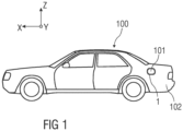
- FIG 1 shows a vehicle 100 with an opening 101 in a vehicle outer skin 102.
- the opening 101 is, for example, a tank opening or loading opening.
- the opening 101 is, for example, by means of a flap unit 1 covered, which is described in more detail below.
- the flap unit 1 can be installed in the area of the opening 101 in the outer skin 102 of the vehicle.
- a valve unit 1 is described below in a Cartesian coordinate system defined by three mutually perpendicular spatial directions.
- a longitudinal direction X is substantially horizontal to and preferably parallel to a longitudinal direction of the vehicle 100, which corresponds to the usual direction of travel of the vehicle 100.
- a transverse direction Y which runs perpendicular to the longitudinal direction X, is likewise oriented horizontally in the vehicle 100 and runs parallel to a transverse direction Y of the vehicle 100.
- a vertical direction Z runs perpendicular to the longitudinal direction X and perpendicular to the transverse direction Y.
- a vertical arrangement should be understood to mean an arrangement parallel to the vertical Z direction.
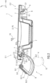
- figure 2 shows a schematic sectional view of a first embodiment of a flap unit 1 with a screen 2.
- the flap unit 1 comprises at least the screen 2 and a frame 3 .
- the screen 2 is arranged within a peripheral area of the frame 3 .
- the flap unit 1 is inserted with the frame 3 into the opening 101 in the vehicle outer skin 102 and fixed there.
- the frame 3 forms an edge of the opening 101, for example.
- figure 2 shows the screen 2 in a closed position P0, in which the screen 2 terminates flush with the frame 3 in particular.
- the panel 2 is used to cover an opening 101, in particular a loading opening or tank opening, of a vehicle 100, not shown that the panel 2 terminates flush with the frame 3 as well as flush with the outer skin 102 of the vehicle.
- the panel 2 is a movable panel 2 and is designed, for example, as a closure cover or a closure flap for the loading opening or tank opening.
- the panel 2 can be cup-shaped as shown.
- the aperture 2 can be disc-shaped. Facing away from the frame 3, the panel 2 has a surface shape that corresponds to a vehicle outer skin 102, in particular a largely flat or slightly curved shape.
- the aperture 2 is set up in such a way that it can be actuated and/or adjusted both electrically and manually.
- the aperture 2 can be adjusted electrically.
- An electric drive mechanism 4 is coupled, for example, to an adjusting mechanism 5 for the panel 2 and can be designed, for example, as a motor drive, in particular a spindle drive or a gear drive.
- the drive mechanism 4 and the adjustment mechanism 5 are arranged on a drive end 2.1 of the panel 2 and coupled to it.
- the screen On a holding end 2.2 of the screen 2 opposite the drive end 2.1, the screen is provided with a locking mechanism 6, for example a locking hook 6.1.
- the panel 2 can be releasably locked to the frame 3 by means of the locking mechanism 6 .
- the closure mechanism 6 is designed as a latching mechanism, in particular a positive latching connection. In the closed position P0 of the diaphragm 2, a counter bearing for the drive end 2.1 of the diaphragm 2 is thus formed on the holding end 2.2 of the diaphragm 2 facing away from the drive.
- the latching hook 6.1 engages, for example, in the closed position P0 of the panel 2 in an undercut 3.1 of the frame 3 in a releasably locking manner.
- the cover 2 is provided on the inside with a seal 7, for example a sealing ring, sealing lips and/or sealing strip.
- a seal 7 in the direction of the panel 2, in particular a sealing ring, sealing lips and/or sealing strip.
- the adjustment mechanism 5 can alternatively be coupled to a manual actuating mechanism for the panel 2, which is not shown in detail.
- a manual actuation mechanism is in particular coupled directly to the panel 2 and can be designed, for example, as a pressure actuation, in particular a so-called push-push mechanism, on the panel 2 .
- the shutter 2 can be moved both during an opening movement of the shutter 2 from the closed position P0 to an open position P2 (shown in Fig figure 5 ) as well as during a closing movement of the panel 2 from the open position P2 into the closed position P0 about a first axis of rotation 9, wherein the panel 2 can be pivoted about a second axis of rotation 10 relative to the adjustment mechanism 5 and at least partially translationally into a partially raised intermediate position P1 (shown in figure 3 ) is movable.
- the panel 2 When the panel 2 is moved from the partially raised intermediate position P1 to the open position P2 and vice versa, the panel 2 can be pivoted about the first axis of rotation 9 together with the adjustment mechanism 5 .
- the adjusting mechanism 5 can be designed as a double swivel joint 8 .
- the double swivel joint 8 comprises a first swivel joint 8.1, which is articulated to the frame 3 and is connected to a second swivel joint 8.3, which is articulated to the panel 2, via a connecting member 8.2.
- the adjusting mechanism 5 of the present panel 2 includes an additional joint, in particular the second pivot joint 8.3.
- the connecting member 8.2 is designed in particular as a pivoting lever, coupling lever or adjusting lever or pivoting arm, coupling arm or adjusting arm.
- the connecting member 8.2 is coupled on the one hand to the screen 2 and on the other hand is mounted on the frame 3 such that it can pivot about the first axis of rotation 9 by means of the first pivot joint 8.1.
- the panel 2 is pivotally mounted relative to the frame 3 by means of the pivotally mounted connecting member 8.2.
- the connecting link 8.2 can be made in one piece.
- the adjustment mechanism 5 has a joint socket 3.2 arranged on the frame 3 for the first pivot joint 8.1.
- the joint socket 3.2 is formed in the area of the drive end 2.1.
- the connecting link 8.2 is designed in section as a 2-legged, L-shaped, hook-shaped or arc-shaped pivoting lever.
- the connecting member 8.2 has the first rotary joint 8.1 on one end facing the frame 3, in particular the joint socket 3.2, and an adjusting pin 8.4 on one end facing the panel 2.
- the first rotary joint 8.1 is sleeve-shaped or cylindrical or spherical.
- Two stop arms 3.2.1 and 3.2.2 protrude from the joint socket 3.2 and serve as end stops for the adjusting mechanism 5 of the panel 2, in particular for the double swivel joint 8, for example for its connecting link 8.2.
- the stop arms 3.2.1 and 3.2.2 protrude from the socket 3.2 in such a way that the pivoting movement of the shutter 2 between the closed position P0 and the open position P2 (shown in Fig figure 5 ) is limited.
- at least one leg 8.2.1 of the connecting link 8.2 strikes the stop arm 3.2.1 (shown in Fig figure 2 ) and in the open position P2 on the stop arm 3.2.2 (shown in figure 5 ) at.
- the panel 2 also has an inner bearing element 2.3 for the second pivot joint 8.3.
- the panel 2 is pivotally mounted by means of the second pivot joint 8.3 about the second axis of rotation 10 relative to the frame 3 and to the connecting member 8.2.
- the panel 2 can be formed in one piece.
- the panel 2 can be made in several parts, in particular in two parts.
- a spring element 11 can be provided on the drive side, the drive end 2.1, of the panel 2, in particular in the area of the second pivot joint 8.3.
- the shutter 2 is held on the frame 3 in a prestressed manner in the closed position P0 by means of the spring element 11 .
- the greatest possible sealing pressure can be generated in the closed position P0 when the spring element 11 is tensioned, so that the screen 2 is flush with the frame 3 and is in sealing contact with the frame 3 by means of the seals 7.
- the spring element 11 is designed as a bistable torsion spring.
- the spring element 11 has two spring arms 11.1, 11.2. In the closed position P0 of the screen 2, the spring element 11 is tensioned. The spring force of the spring element 11 pulls the two spring arms 11.1 and 11.2 towards one another, as shown by the arrows PF1. As a result, both the aperture pin 2.4 and the adjustment pin 8.4 are subjected to an associated spring force of the relevant spring arm 11.1 or 11.2. As a result of this spring force of spring element 11, panel 2 is pulled in the direction of frame 3 according to arrow PF2, so that panel 2 rests against frame 3 in a form-fitting and sealing manner.
- first axis of rotation 9 of the first pivot joint 8.1 and the second axis of rotation 10 of the second pivot joint 8.3 are parallel arranged to each other.
- the axes of rotation 9, 10 can run vertically or horizontally depending on the opening direction of the panel 2, correspondingly horizontally or vertically.
- the axes of rotation 9, 10 run vertically and the panel 2 can be opened in the horizontal direction according to arrow PF3.
- the connecting link 8.2 in particular designed as an adjusting lever, pivoting lever or coupling lever, is configured in such a way that it moves on the first rotary joint 8.1 about its first axis of rotation 9 in a first arc 12.
- the panel 2, in particular a closure cover, is configured in such a way that it moves on the second rotary joint 8.3 about its second axis of rotation 10 in a second arc 13 according to arrow PF3.
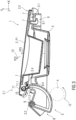
- the shutter 2 can be moved into the partially raised intermediate position P1, which is shown in figure 3 is shown.
- figure 3 shows a sectional view of the flap unit 1 with the screen 2 in the partially raised intermediate position P1, in which the screen 2 contacts the frame 3 at least in certain areas.
- the panel 2 can be positioned or positioned in relation to the frame 3 by means of the adjustment mechanism 5 in the partially raised intermediate position P1 in such a way that the drive end 2.1 of the panel 2 is raised and spaced from the frame 3 and the opposite drive-remote holding end 2.2 of the panel 2 with the frame 3 continues to be contacted, with the panel 2 already being unlocked.
- the latching hook 6.1 is disengaged from the undercut 3.1, which is designed as a latching projection on the frame 3, for example.
- the adjusting mechanism 5 is designed, for example, in such a way that it moves the panel 2 out of the plane of the frame 3, in particular initially pivots it into the raised intermediate position P1.
- the adjustment mechanism 5 is set up such that the panel 2 is first moved in the first arc 12 about the first axis of rotation 9, so that the drive end 2.1 is raised relative to the frame 3 and the vehicle outer skin 102 and the holding end 2.2 is unlocked.
- the opposite holding end 2.2 remains in contact with the frame 3.
- the flap unit 1 can be designed without a frame.
- the panel 2 continues to contact the vehicle outer skin 102 with its holding end 2.2.
- the spring element 11 relaxes, with the spring arm 11.2 being moved in the direction of the panel 2 according to the arrow PF4, so that the panel 2 pivots relative to the adjustment mechanism 5 about the second axis of rotation 10 in a second arc 13 according to the arrow PF3 and at least partially translationally according to the arrow PF5 is moved so that the drive end 2.1 of the panel 2 is raised and the panel 2 is unlocked, in particular the latching hook 6.1 disengages from the undercut 3.1.
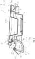
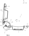
- figure 4 shows a sectional view of the flap unit 1 with the screen 2 in a completely raised intermediate position P1.1, in particular completely spaced apart from the frame 3, in which the holding end 2.2 of the screen 2 no longer makes contact with the frame 3.
- the panel 2 reaches this fully raised intermediate position P1.1 by further movement of the adjustment mechanism 5, in particular of the connecting member 8.2, about the first axis of rotation 9 according to arrow PF6.
- the screen 2 is pivoted about the first axis of rotation 9 together with the connecting member 8.2.
- the spring element 11 remains relaxed.
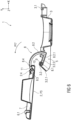
- figure 5 shows a sectional view of the flap unit 1 with the panel 2 in the open position P2.
- the screen 2 is positioned largely perpendicular to the frame 3.
- the spring element 11 remains relaxed.
- the Aperture 2 has been pivoted together with the adjusting mechanism 5 about the first axis of rotation 9 according to arrow PF 3 into the open position P2.
- figure 6 shows a sectional view of the flap unit 1 with the panel 2 in a misuse position P3.
- the diaphragm 2 was manually actuated, in particular pivoted, relative to the adjustment mechanism 5 about the second axis of rotation 10 according to arrow PF7.
- the adjusting mechanism 5 is fixed due to the impact of the leg 8.2.1 on the stop arm 3.2.2 of the frame 3.
- the panel 2 can thus be pivoted about the second axis of rotation 10 relative to the frame 3 and to the adjustment mechanism 5 by means of the second rotary joint 8.3.
- the spring element 11 is tensioned in that the diaphragm pin 2.4 entrains the corresponding spring arm 11.1 during the pivoting movement of the diaphragm 2 according to arrow PF7. If the shutter 2 is no longer actuated, then due to the relaxation of the spring element 11 it is automatically returned to the open position P2 and further until the spring element 11 is relaxed.
- figure 7 shows a sectional view of the flap unit 1 with the panel 2 during a closing movement of the panel 2 as a result of the relaxation of the spring element 11 according to arrow PF8.
Landscapes
- Engineering & Computer Science (AREA)
- Life Sciences & Earth Sciences (AREA)
- Sustainable Development (AREA)
- Sustainable Energy (AREA)
- Chemical & Material Sciences (AREA)
- Combustion & Propulsion (AREA)
- Transportation (AREA)
- Mechanical Engineering (AREA)
- Cooling, Air Intake And Gas Exhaust, And Fuel Tank Arrangements In Propulsion Units (AREA)
- Superstructure Of Vehicle (AREA)
- Specific Sealing Or Ventilating Devices For Doors And Windows (AREA)
- Power-Operated Mechanisms For Wings (AREA)
Applications Claiming Priority (1)
| Application Number | Priority Date | Filing Date | Title |
|---|---|---|---|
| DE102021209348.5A DE102021209348A1 (de) | 2021-08-25 | 2021-08-25 | Klappeneinheit für eine Öffnung an einem Fahrzeug |
Publications (2)
| Publication Number | Publication Date |
|---|---|
| EP4166366A1 true EP4166366A1 (fr) | 2023-04-19 |
| EP4166366B1 EP4166366B1 (fr) | 2024-03-13 |
Family
ID=83112454
Family Applications (1)
| Application Number | Title | Priority Date | Filing Date |
|---|---|---|---|
| EP22192150.5A Active EP4166366B1 (fr) | 2021-08-25 | 2022-08-25 | Unité de volet pour une ouverture d'un véhicule et véhicule |
Country Status (4)
| Country | Link |
|---|---|
| US (1) | US12146358B2 (fr) |
| EP (1) | EP4166366B1 (fr) |
| CN (1) | CN115891629B (fr) |
| DE (1) | DE102021209348A1 (fr) |
Families Citing this family (4)
| Publication number | Priority date | Publication date | Assignee | Title |
|---|---|---|---|---|
| CN116136140A (zh) * | 2021-11-18 | 2023-05-19 | 伊利诺斯工具制品有限公司 | 用于锁定充电、加油或检修翻盖的锁定装置 |
| US12533946B2 (en) * | 2022-04-27 | 2026-01-27 | Illinois Tool Works Inc. | Charge, fuel, or service recess for a vehicle |
| JP2025091732A (ja) * | 2023-12-07 | 2025-06-19 | トヨタ自動車株式会社 | 充電リッド構造 |
| DE102024103356A1 (de) * | 2024-02-07 | 2025-08-07 | Bos Gmbh & Co. Kg | Ladeklappenanordnung für ein Kraftfahrzeug |
Citations (6)
| Publication number | Priority date | Publication date | Assignee | Title |
|---|---|---|---|---|
| DE19919251A1 (de) * | 1999-04-28 | 2000-11-02 | Bayerische Motoren Werke Ag | Verschlußeinrichtung für einen Kraftstoffbehälter eines Kraftfahrzeuges |
| DE102012009018A1 (de) | 2012-05-05 | 2013-11-07 | Volkswagen Aktiengesellschaft | Schwenkbar gelagerte Klappe an einem Fahrzeug sowie Fahrzeug |
| DE202016105735U1 (de) * | 2016-10-13 | 2016-10-26 | Dr. Schneider Kunststoffwerke Gmbh | Einrichtung zum Öffnen und Schließen einer Tankklappe |
| DE102017223396A1 (de) * | 2017-12-20 | 2019-06-27 | Bayerische Motoren Werke Aktiengesellschaft | Abdeckungssystem sowie Fahrzeug |
| CZ2019398A3 (cs) * | 2019-06-20 | 2021-01-13 | Brano A.S. | Nabíjecí modul automobilu |
| DE102020207669A1 (de) | 2020-06-22 | 2021-12-23 | Bos Gmbh & Co. Kg | Tankklappenanordnung für ein Kraftfahrzeug |
Family Cites Families (11)
| Publication number | Priority date | Publication date | Assignee | Title |
|---|---|---|---|---|
| DE3702903A1 (de) * | 1987-01-31 | 1988-08-11 | Porsche Ag | Klappe zum verschliessen einer karosseriemulde |
| DE19517705C2 (de) * | 1995-05-13 | 1998-11-05 | Itw Ateco Gmbh | Tankmulde |
| DE19604959A1 (de) | 1996-02-10 | 1997-08-14 | Webasto Karosseriesysteme | Verschlußkappe für Karosserieöffnungen |
| DE19650594C2 (de) * | 1996-12-06 | 1998-09-17 | Bayerische Motoren Werke Ag | Anordnung einer Tankklappe an einem Kraftfahrzeug |
| KR20010053834A (ko) * | 1999-12-02 | 2001-07-02 | 이계안 | 연료 필러 도어의 결합 구조 |
| KR100513884B1 (ko) * | 2003-11-18 | 2005-09-09 | 현대자동차주식회사 | 자동차 연료주입구의 개폐구조 |
| DE102004010294B4 (de) * | 2004-03-03 | 2007-05-03 | Itw Automotive Products Gmbh & Co. Kg | Tankmulde für Automobile |
| JP2005343367A (ja) * | 2004-06-04 | 2005-12-15 | Nissan Motor Co Ltd | フューエルリッドの取付構造 |
| JP6788938B2 (ja) * | 2016-11-18 | 2020-11-25 | 株式会社Fts | 給油口蓋の取付構造 |
| DE102020120242A1 (de) * | 2020-07-31 | 2022-02-03 | Illinois Tool Works Inc. | Mechanismus zum verschwenken einer lade- oder tankklappe, anordnung aus einer lade- oder tankmulde, mindestens einer lade- oder tankklappe und mindestens einem solchen mechanismus sowie fahrzeug mit mindestens einer solchen anordnung |
| US11548379B2 (en) * | 2021-02-03 | 2023-01-10 | Ford Global Technologies, Llc | Electrified vehicle including remote terminals accessible via charging port door |
-
2021
- 2021-08-25 DE DE102021209348.5A patent/DE102021209348A1/de active Pending
-
2022
- 2022-08-25 US US17/822,149 patent/US12146358B2/en active Active
- 2022-08-25 EP EP22192150.5A patent/EP4166366B1/fr active Active
- 2022-08-25 CN CN202211023656.6A patent/CN115891629B/zh active Active
Patent Citations (6)
| Publication number | Priority date | Publication date | Assignee | Title |
|---|---|---|---|---|
| DE19919251A1 (de) * | 1999-04-28 | 2000-11-02 | Bayerische Motoren Werke Ag | Verschlußeinrichtung für einen Kraftstoffbehälter eines Kraftfahrzeuges |
| DE102012009018A1 (de) | 2012-05-05 | 2013-11-07 | Volkswagen Aktiengesellschaft | Schwenkbar gelagerte Klappe an einem Fahrzeug sowie Fahrzeug |
| DE202016105735U1 (de) * | 2016-10-13 | 2016-10-26 | Dr. Schneider Kunststoffwerke Gmbh | Einrichtung zum Öffnen und Schließen einer Tankklappe |
| DE102017223396A1 (de) * | 2017-12-20 | 2019-06-27 | Bayerische Motoren Werke Aktiengesellschaft | Abdeckungssystem sowie Fahrzeug |
| CZ2019398A3 (cs) * | 2019-06-20 | 2021-01-13 | Brano A.S. | Nabíjecí modul automobilu |
| DE102020207669A1 (de) | 2020-06-22 | 2021-12-23 | Bos Gmbh & Co. Kg | Tankklappenanordnung für ein Kraftfahrzeug |
Also Published As
| Publication number | Publication date |
|---|---|
| US12146358B2 (en) | 2024-11-19 |
| EP4166366B1 (fr) | 2024-03-13 |
| CN115891629A (zh) | 2023-04-04 |
| CN115891629B (zh) | 2025-09-23 |
| US20230061574A1 (en) | 2023-03-02 |
| DE102021209348A1 (de) | 2023-03-02 |
Similar Documents
| Publication | Publication Date | Title |
|---|---|---|
| EP4166366B1 (fr) | Unité de volet pour une ouverture d'un véhicule et véhicule | |
| DE102016120760B4 (de) | Tank- oder Ladeklappenanordnung für ein Fahrzeug | |
| EP2020328A1 (fr) | Unité de trappe d'obturation de réservoir | |
| WO2015114155A1 (fr) | Dispositif de fermeture pour ouverture de remplissage ou de raccordement à un véhicule | |
| EP0222160A2 (fr) | Mécanisme d'actionnement pour une porte de chargement de fret | |
| DE202005006942U1 (de) | Schiebetür für ein Kraftfahrzeug | |
| EP1617031A2 (fr) | Porte coulissante pour un véhicule | |
| DE102009018188A1 (de) | Vorrichtung zum automatischen Schließen einer Fahrzeugtür | |
| EP3277899B1 (fr) | Système de poignée de porte d'un véhicule automobile | |
| DE102013218388A1 (de) | Fahrzeug mit zumindest einem Fensterausschnitt für eine Fensterscheibe | |
| EP1920962A2 (fr) | Capote pour un véhicule automobile, en particulier pour un véhicule de type cabriolet, avec un toit pliant | |
| DE10153724A1 (de) | Fahrzeugklappe | |
| DE102005033098B4 (de) | Heckklappe für ein Kraftfahrzeug | |
| DE102009001227A1 (de) | Heckklappenanordnung für ein Kraftfahrzeug | |
| DE10117769B4 (de) | Vorrichtung zur Unterstützung einer Öffnungsbewegung einer Fahrzeugklappe | |
| DE102011054407A1 (de) | Ver- und Entriegelungssystem | |
| DE202023107341U1 (de) | Schloss mit Schwenkriegel | |
| DE3419543C2 (de) | Verschluß für Seitentüren von Kraftfahrzeugen | |
| DE112022004551T5 (de) | Vorrichtung zum öffnen und schliessen eines deckels | |
| DE69009190T2 (de) | Schlossdichtung. | |
| DE10359144B4 (de) | Vorrichtung zur gemeinsamen elektromechanischen Steuerung mehrerer technischer Einrichtungen | |
| WO2020212070A1 (fr) | Dispositif d'ouverture d'élément en forme d'ailette, ainsi que véhicule | |
| DE202005015687U1 (de) | Kraftfahrzeugschloß | |
| DE102007061442B4 (de) | Verriegelungsvorrichtung mit kraftbetätigtem Schließelement | |
| EP1525362A1 (fr) | Dispositif de fermeture |
Legal Events
| Date | Code | Title | Description |
|---|---|---|---|
| PUAI | Public reference made under article 153(3) epc to a published international application that has entered the european phase |
Free format text: ORIGINAL CODE: 0009012 |
|
| STAA | Information on the status of an ep patent application or granted ep patent |
Free format text: STATUS: THE APPLICATION HAS BEEN PUBLISHED |
|
| AK | Designated contracting states |
Kind code of ref document: A1 Designated state(s): AL AT BE BG CH CY CZ DE DK EE ES FI FR GB GR HR HU IE IS IT LI LT LU LV MC MK MT NL NO PL PT RO RS SE SI SK SM TR |
|
| STAA | Information on the status of an ep patent application or granted ep patent |
Free format text: STATUS: REQUEST FOR EXAMINATION WAS MADE |
|
| 17P | Request for examination filed |
Effective date: 20230613 |
|
| RBV | Designated contracting states (corrected) |
Designated state(s): AL AT BE BG CH CY CZ DE DK EE ES FI FR GB GR HR HU IE IS IT LI LT LU LV MC MK MT NL NO PL PT RO RS SE SI SK SM TR |
|
| GRAP | Despatch of communication of intention to grant a patent |
Free format text: ORIGINAL CODE: EPIDOSNIGR1 |
|
| STAA | Information on the status of an ep patent application or granted ep patent |
Free format text: STATUS: GRANT OF PATENT IS INTENDED |
|
| INTG | Intention to grant announced |
Effective date: 20230911 |
|
| P01 | Opt-out of the competence of the unified patent court (upc) registered |
Effective date: 20231006 |
|
| GRAS | Grant fee paid |
Free format text: ORIGINAL CODE: EPIDOSNIGR3 |
|
| GRAA | (expected) grant |
Free format text: ORIGINAL CODE: 0009210 |
|
| STAA | Information on the status of an ep patent application or granted ep patent |
Free format text: STATUS: THE PATENT HAS BEEN GRANTED |
|
| AK | Designated contracting states |
Kind code of ref document: B1 Designated state(s): AL AT BE BG CH CY CZ DE DK EE ES FI FR GB GR HR HU IE IS IT LI LT LU LV MC MK MT NL NO PL PT RO RS SE SI SK SM TR |
|
| REG | Reference to a national code |
Ref country code: GB Ref legal event code: FG4D Free format text: NOT ENGLISH |
|
| REG | Reference to a national code |
Ref country code: CH Ref legal event code: EP |
|
| REG | Reference to a national code |
Ref country code: DE Ref legal event code: R096 Ref document number: 502022000606 Country of ref document: DE |
|
| REG | Reference to a national code |
Ref country code: IE Ref legal event code: FG4D Free format text: LANGUAGE OF EP DOCUMENT: GERMAN |
|
| PG25 | Lapsed in a contracting state [announced via postgrant information from national office to epo] |
Ref country code: LT Free format text: LAPSE BECAUSE OF FAILURE TO SUBMIT A TRANSLATION OF THE DESCRIPTION OR TO PAY THE FEE WITHIN THE PRESCRIBED TIME-LIMIT Effective date: 20240313 |
|
| REG | Reference to a national code |
Ref country code: LT Ref legal event code: MG9D |
|
| PG25 | Lapsed in a contracting state [announced via postgrant information from national office to epo] |
Ref country code: GR Free format text: LAPSE BECAUSE OF FAILURE TO SUBMIT A TRANSLATION OF THE DESCRIPTION OR TO PAY THE FEE WITHIN THE PRESCRIBED TIME-LIMIT Effective date: 20240614 |
|
| REG | Reference to a national code |
Ref country code: NL Ref legal event code: MP Effective date: 20240313 |
|
| PG25 | Lapsed in a contracting state [announced via postgrant information from national office to epo] |
Ref country code: HR Free format text: LAPSE BECAUSE OF FAILURE TO SUBMIT A TRANSLATION OF THE DESCRIPTION OR TO PAY THE FEE WITHIN THE PRESCRIBED TIME-LIMIT Effective date: 20240313 Ref country code: RS Free format text: LAPSE BECAUSE OF FAILURE TO SUBMIT A TRANSLATION OF THE DESCRIPTION OR TO PAY THE FEE WITHIN THE PRESCRIBED TIME-LIMIT Effective date: 20240613 |
|
| PG25 | Lapsed in a contracting state [announced via postgrant information from national office to epo] |
Ref country code: ES Free format text: LAPSE BECAUSE OF FAILURE TO SUBMIT A TRANSLATION OF THE DESCRIPTION OR TO PAY THE FEE WITHIN THE PRESCRIBED TIME-LIMIT Effective date: 20240313 |
|
| PG25 | Lapsed in a contracting state [announced via postgrant information from national office to epo] |
Ref country code: RS Free format text: LAPSE BECAUSE OF FAILURE TO SUBMIT A TRANSLATION OF THE DESCRIPTION OR TO PAY THE FEE WITHIN THE PRESCRIBED TIME-LIMIT Effective date: 20240613 Ref country code: NO Free format text: LAPSE BECAUSE OF FAILURE TO SUBMIT A TRANSLATION OF THE DESCRIPTION OR TO PAY THE FEE WITHIN THE PRESCRIBED TIME-LIMIT Effective date: 20240613 Ref country code: LT Free format text: LAPSE BECAUSE OF FAILURE TO SUBMIT A TRANSLATION OF THE DESCRIPTION OR TO PAY THE FEE WITHIN THE PRESCRIBED TIME-LIMIT Effective date: 20240313 Ref country code: HR Free format text: LAPSE BECAUSE OF FAILURE TO SUBMIT A TRANSLATION OF THE DESCRIPTION OR TO PAY THE FEE WITHIN THE PRESCRIBED TIME-LIMIT Effective date: 20240313 Ref country code: GR Free format text: LAPSE BECAUSE OF FAILURE TO SUBMIT A TRANSLATION OF THE DESCRIPTION OR TO PAY THE FEE WITHIN THE PRESCRIBED TIME-LIMIT Effective date: 20240614 Ref country code: FI Free format text: LAPSE BECAUSE OF FAILURE TO SUBMIT A TRANSLATION OF THE DESCRIPTION OR TO PAY THE FEE WITHIN THE PRESCRIBED TIME-LIMIT Effective date: 20240313 Ref country code: ES Free format text: LAPSE BECAUSE OF FAILURE TO SUBMIT A TRANSLATION OF THE DESCRIPTION OR TO PAY THE FEE WITHIN THE PRESCRIBED TIME-LIMIT Effective date: 20240313 Ref country code: BG Free format text: LAPSE BECAUSE OF FAILURE TO SUBMIT A TRANSLATION OF THE DESCRIPTION OR TO PAY THE FEE WITHIN THE PRESCRIBED TIME-LIMIT Effective date: 20240313 |
|
| PG25 | Lapsed in a contracting state [announced via postgrant information from national office to epo] |
Ref country code: SE Free format text: LAPSE BECAUSE OF FAILURE TO SUBMIT A TRANSLATION OF THE DESCRIPTION OR TO PAY THE FEE WITHIN THE PRESCRIBED TIME-LIMIT Effective date: 20240313 Ref country code: LV Free format text: LAPSE BECAUSE OF FAILURE TO SUBMIT A TRANSLATION OF THE DESCRIPTION OR TO PAY THE FEE WITHIN THE PRESCRIBED TIME-LIMIT Effective date: 20240313 |
|
| PG25 | Lapsed in a contracting state [announced via postgrant information from national office to epo] |
Ref country code: NL Free format text: LAPSE BECAUSE OF FAILURE TO SUBMIT A TRANSLATION OF THE DESCRIPTION OR TO PAY THE FEE WITHIN THE PRESCRIBED TIME-LIMIT Effective date: 20240313 |
|
| PG25 | Lapsed in a contracting state [announced via postgrant information from national office to epo] |
Ref country code: NL Free format text: LAPSE BECAUSE OF FAILURE TO SUBMIT A TRANSLATION OF THE DESCRIPTION OR TO PAY THE FEE WITHIN THE PRESCRIBED TIME-LIMIT Effective date: 20240313 |
|
| PG25 | Lapsed in a contracting state [announced via postgrant information from national office to epo] |
Ref country code: IS Free format text: LAPSE BECAUSE OF FAILURE TO SUBMIT A TRANSLATION OF THE DESCRIPTION OR TO PAY THE FEE WITHIN THE PRESCRIBED TIME-LIMIT Effective date: 20240713 |
|
| PG25 | Lapsed in a contracting state [announced via postgrant information from national office to epo] |
Ref country code: PT Free format text: LAPSE BECAUSE OF FAILURE TO SUBMIT A TRANSLATION OF THE DESCRIPTION OR TO PAY THE FEE WITHIN THE PRESCRIBED TIME-LIMIT Effective date: 20240715 Ref country code: SM Free format text: LAPSE BECAUSE OF FAILURE TO SUBMIT A TRANSLATION OF THE DESCRIPTION OR TO PAY THE FEE WITHIN THE PRESCRIBED TIME-LIMIT Effective date: 20240313 |
|
| PG25 | Lapsed in a contracting state [announced via postgrant information from national office to epo] |
Ref country code: EE Free format text: LAPSE BECAUSE OF FAILURE TO SUBMIT A TRANSLATION OF THE DESCRIPTION OR TO PAY THE FEE WITHIN THE PRESCRIBED TIME-LIMIT Effective date: 20240313 Ref country code: CZ Free format text: LAPSE BECAUSE OF FAILURE TO SUBMIT A TRANSLATION OF THE DESCRIPTION OR TO PAY THE FEE WITHIN THE PRESCRIBED TIME-LIMIT Effective date: 20240313 |
|
| PG25 | Lapsed in a contracting state [announced via postgrant information from national office to epo] |
Ref country code: PL Free format text: LAPSE BECAUSE OF FAILURE TO SUBMIT A TRANSLATION OF THE DESCRIPTION OR TO PAY THE FEE WITHIN THE PRESCRIBED TIME-LIMIT Effective date: 20240313 |
|
| PG25 | Lapsed in a contracting state [announced via postgrant information from national office to epo] |
Ref country code: SK Free format text: LAPSE BECAUSE OF FAILURE TO SUBMIT A TRANSLATION OF THE DESCRIPTION OR TO PAY THE FEE WITHIN THE PRESCRIBED TIME-LIMIT Effective date: 20240313 |
|
| PG25 | Lapsed in a contracting state [announced via postgrant information from national office to epo] |
Ref country code: SM Free format text: LAPSE BECAUSE OF FAILURE TO SUBMIT A TRANSLATION OF THE DESCRIPTION OR TO PAY THE FEE WITHIN THE PRESCRIBED TIME-LIMIT Effective date: 20240313 Ref country code: SK Free format text: LAPSE BECAUSE OF FAILURE TO SUBMIT A TRANSLATION OF THE DESCRIPTION OR TO PAY THE FEE WITHIN THE PRESCRIBED TIME-LIMIT Effective date: 20240313 Ref country code: RO Free format text: LAPSE BECAUSE OF FAILURE TO SUBMIT A TRANSLATION OF THE DESCRIPTION OR TO PAY THE FEE WITHIN THE PRESCRIBED TIME-LIMIT Effective date: 20240313 Ref country code: PT Free format text: LAPSE BECAUSE OF FAILURE TO SUBMIT A TRANSLATION OF THE DESCRIPTION OR TO PAY THE FEE WITHIN THE PRESCRIBED TIME-LIMIT Effective date: 20240715 Ref country code: PL Free format text: LAPSE BECAUSE OF FAILURE TO SUBMIT A TRANSLATION OF THE DESCRIPTION OR TO PAY THE FEE WITHIN THE PRESCRIBED TIME-LIMIT Effective date: 20240313 Ref country code: IS Free format text: LAPSE BECAUSE OF FAILURE TO SUBMIT A TRANSLATION OF THE DESCRIPTION OR TO PAY THE FEE WITHIN THE PRESCRIBED TIME-LIMIT Effective date: 20240713 Ref country code: EE Free format text: LAPSE BECAUSE OF FAILURE TO SUBMIT A TRANSLATION OF THE DESCRIPTION OR TO PAY THE FEE WITHIN THE PRESCRIBED TIME-LIMIT Effective date: 20240313 Ref country code: CZ Free format text: LAPSE BECAUSE OF FAILURE TO SUBMIT A TRANSLATION OF THE DESCRIPTION OR TO PAY THE FEE WITHIN THE PRESCRIBED TIME-LIMIT Effective date: 20240313 |
|
| PG25 | Lapsed in a contracting state [announced via postgrant information from national office to epo] |
Ref country code: IT Free format text: LAPSE BECAUSE OF FAILURE TO SUBMIT A TRANSLATION OF THE DESCRIPTION OR TO PAY THE FEE WITHIN THE PRESCRIBED TIME-LIMIT Effective date: 20240313 |
|
| REG | Reference to a national code |
Ref country code: DE Ref legal event code: R097 Ref document number: 502022000606 Country of ref document: DE |
|
| PG25 | Lapsed in a contracting state [announced via postgrant information from national office to epo] |
Ref country code: IT Free format text: LAPSE BECAUSE OF FAILURE TO SUBMIT A TRANSLATION OF THE DESCRIPTION OR TO PAY THE FEE WITHIN THE PRESCRIBED TIME-LIMIT Effective date: 20240313 |
|
| PG25 | Lapsed in a contracting state [announced via postgrant information from national office to epo] |
Ref country code: DK Free format text: LAPSE BECAUSE OF FAILURE TO SUBMIT A TRANSLATION OF THE DESCRIPTION OR TO PAY THE FEE WITHIN THE PRESCRIBED TIME-LIMIT Effective date: 20240313 |
|
| PLBE | No opposition filed within time limit |
Free format text: ORIGINAL CODE: 0009261 |
|
| STAA | Information on the status of an ep patent application or granted ep patent |
Free format text: STATUS: NO OPPOSITION FILED WITHIN TIME LIMIT |
|
| PG25 | Lapsed in a contracting state [announced via postgrant information from national office to epo] |
Ref country code: DK Free format text: LAPSE BECAUSE OF FAILURE TO SUBMIT A TRANSLATION OF THE DESCRIPTION OR TO PAY THE FEE WITHIN THE PRESCRIBED TIME-LIMIT Effective date: 20240313 |
|
| 26N | No opposition filed |
Effective date: 20241216 |
|
| PG25 | Lapsed in a contracting state [announced via postgrant information from national office to epo] |
Ref country code: LU Free format text: LAPSE BECAUSE OF NON-PAYMENT OF DUE FEES Effective date: 20240825 |
|
| PG25 | Lapsed in a contracting state [announced via postgrant information from national office to epo] |
Ref country code: SI Free format text: LAPSE BECAUSE OF FAILURE TO SUBMIT A TRANSLATION OF THE DESCRIPTION OR TO PAY THE FEE WITHIN THE PRESCRIBED TIME-LIMIT Effective date: 20240313 Ref country code: MC Free format text: LAPSE BECAUSE OF FAILURE TO SUBMIT A TRANSLATION OF THE DESCRIPTION OR TO PAY THE FEE WITHIN THE PRESCRIBED TIME-LIMIT Effective date: 20240313 |
|
| REG | Reference to a national code |
Ref country code: BE Ref legal event code: MM Effective date: 20240831 |
|
| PG25 | Lapsed in a contracting state [announced via postgrant information from national office to epo] |
Ref country code: BE Free format text: LAPSE BECAUSE OF NON-PAYMENT OF DUE FEES Effective date: 20240831 |
|
| PG25 | Lapsed in a contracting state [announced via postgrant information from national office to epo] |
Ref country code: IE Free format text: LAPSE BECAUSE OF NON-PAYMENT OF DUE FEES Effective date: 20240825 |
|
| PGFP | Annual fee paid to national office [announced via postgrant information from national office to epo] |
Ref country code: DE Payment date: 20250819 Year of fee payment: 4 |
|
| PGFP | Annual fee paid to national office [announced via postgrant information from national office to epo] |
Ref country code: AT Payment date: 20251020 Year of fee payment: 4 Ref country code: FR Payment date: 20250821 Year of fee payment: 4 |
|
| PG25 | Lapsed in a contracting state [announced via postgrant information from national office to epo] |
Ref country code: CY Free format text: LAPSE BECAUSE OF FAILURE TO SUBMIT A TRANSLATION OF THE DESCRIPTION OR TO PAY THE FEE WITHIN THE PRESCRIBED TIME-LIMIT; INVALID AB INITIO Effective date: 20220825 |