EP4166366A1 - Vehicle and valve unit for an opening on a vehicle - Google Patents
Vehicle and valve unit for an opening on a vehicle Download PDFInfo
- Publication number
- EP4166366A1 EP4166366A1 EP22192150.5A EP22192150A EP4166366A1 EP 4166366 A1 EP4166366 A1 EP 4166366A1 EP 22192150 A EP22192150 A EP 22192150A EP 4166366 A1 EP4166366 A1 EP 4166366A1
- Authority
- EP
- European Patent Office
- Prior art keywords
- panel
- frame
- opening
- flap unit
- screen
- Prior art date
- Legal status (The legal status is an assumption and is not a legal conclusion. Google has not performed a legal analysis and makes no representation as to the accuracy of the status listed.)
- Granted
Links
- 230000002093 peripheral effect Effects 0.000 abstract description 2
- 238000007789 sealing Methods 0.000 description 12
- 230000008878 coupling Effects 0.000 description 6
- 238000010168 coupling process Methods 0.000 description 6
- 238000005859 coupling reaction Methods 0.000 description 6
- 238000011161 development Methods 0.000 description 2
- 230000018109 developmental process Effects 0.000 description 2
- 108010000020 Platelet Factor 3 Proteins 0.000 description 1
- 238000010276 construction Methods 0.000 description 1
- 230000001419 dependent effect Effects 0.000 description 1
Images

Classifications
-
- E—FIXED CONSTRUCTIONS
- E05—LOCKS; KEYS; WINDOW OR DOOR FITTINGS; SAFES
- E05F—DEVICES FOR MOVING WINGS INTO OPEN OR CLOSED POSITION; CHECKS FOR WINGS; WING FITTINGS NOT OTHERWISE PROVIDED FOR, CONCERNED WITH THE FUNCTIONING OF THE WING
- E05F1/00—Closers or openers for wings, not otherwise provided for in this subclass
- E05F1/08—Closers or openers for wings, not otherwise provided for in this subclass spring-actuated, e.g. for horizontally sliding wings
- E05F1/10—Closers or openers for wings, not otherwise provided for in this subclass spring-actuated, e.g. for horizontally sliding wings for swinging wings, e.g. counterbalance
-
- B—PERFORMING OPERATIONS; TRANSPORTING
- B60—VEHICLES IN GENERAL
- B60K—ARRANGEMENT OR MOUNTING OF PROPULSION UNITS OR OF TRANSMISSIONS IN VEHICLES; ARRANGEMENT OR MOUNTING OF PLURAL DIVERSE PRIME-MOVERS IN VEHICLES; AUXILIARY DRIVES FOR VEHICLES; INSTRUMENTATION OR DASHBOARDS FOR VEHICLES; ARRANGEMENTS IN CONNECTION WITH COOLING, AIR INTAKE, GAS EXHAUST OR FUEL SUPPLY OF PROPULSION UNITS IN VEHICLES
- B60K15/00—Arrangement in connection with fuel supply of combustion engines or other fuel consuming energy converters, e.g. fuel cells; Mounting or construction of fuel tanks
- B60K15/03—Fuel tanks
- B60K15/04—Tank inlets
- B60K15/05—Inlet covers
-
- E—FIXED CONSTRUCTIONS
- E05—LOCKS; KEYS; WINDOW OR DOOR FITTINGS; SAFES
- E05B—LOCKS; ACCESSORIES THEREFOR; HANDCUFFS
- E05B83/00—Vehicle locks specially adapted for particular types of wing or vehicle
- E05B83/28—Locks for glove compartments, console boxes, fuel inlet covers or the like
- E05B83/34—Locks for glove compartments, console boxes, fuel inlet covers or the like for fuel inlet covers essentially flush with the vehicle surface
-
- B—PERFORMING OPERATIONS; TRANSPORTING
- B60—VEHICLES IN GENERAL
- B60K—ARRANGEMENT OR MOUNTING OF PROPULSION UNITS OR OF TRANSMISSIONS IN VEHICLES; ARRANGEMENT OR MOUNTING OF PLURAL DIVERSE PRIME-MOVERS IN VEHICLES; AUXILIARY DRIVES FOR VEHICLES; INSTRUMENTATION OR DASHBOARDS FOR VEHICLES; ARRANGEMENTS IN CONNECTION WITH COOLING, AIR INTAKE, GAS EXHAUST OR FUEL SUPPLY OF PROPULSION UNITS IN VEHICLES
- B60K15/00—Arrangement in connection with fuel supply of combustion engines or other fuel consuming energy converters, e.g. fuel cells; Mounting or construction of fuel tanks
- B60K15/03—Fuel tanks
- B60K15/04—Tank inlets
- B60K15/05—Inlet covers
- B60K2015/0515—Arrangements for closing or opening of inlet cover
- B60K2015/053—Arrangements for closing or opening of inlet cover with hinged connection to the vehicle body
-
- B—PERFORMING OPERATIONS; TRANSPORTING
- B60—VEHICLES IN GENERAL
- B60K—ARRANGEMENT OR MOUNTING OF PROPULSION UNITS OR OF TRANSMISSIONS IN VEHICLES; ARRANGEMENT OR MOUNTING OF PLURAL DIVERSE PRIME-MOVERS IN VEHICLES; AUXILIARY DRIVES FOR VEHICLES; INSTRUMENTATION OR DASHBOARDS FOR VEHICLES; ARRANGEMENTS IN CONNECTION WITH COOLING, AIR INTAKE, GAS EXHAUST OR FUEL SUPPLY OF PROPULSION UNITS IN VEHICLES
- B60K15/00—Arrangement in connection with fuel supply of combustion engines or other fuel consuming energy converters, e.g. fuel cells; Mounting or construction of fuel tanks
- B60K15/03—Fuel tanks
- B60K15/04—Tank inlets
- B60K15/05—Inlet covers
- B60K2015/0561—Locking means for the inlet cover
-
- E—FIXED CONSTRUCTIONS
- E05—LOCKS; KEYS; WINDOW OR DOOR FITTINGS; SAFES
- E05F—DEVICES FOR MOVING WINGS INTO OPEN OR CLOSED POSITION; CHECKS FOR WINGS; WING FITTINGS NOT OTHERWISE PROVIDED FOR, CONCERNED WITH THE FUNCTIONING OF THE WING
- E05F15/00—Power-operated mechanisms for wings
- E05F15/60—Power-operated mechanisms for wings using electrical actuators
- E05F15/603—Power-operated mechanisms for wings using electrical actuators using rotary electromotors
- E05F15/611—Power-operated mechanisms for wings using electrical actuators using rotary electromotors for swinging wings
-
- E—FIXED CONSTRUCTIONS
- E05—LOCKS; KEYS; WINDOW OR DOOR FITTINGS; SAFES
- E05Y—INDEXING SCHEME RELATING TO HINGES OR OTHER SUSPENSION DEVICES FOR DOORS, WINDOWS OR WINGS AND DEVICES FOR MOVING WINGS INTO OPEN OR CLOSED POSITION, CHECKS FOR WINGS AND WING FITTINGS NOT OTHERWISE PROVIDED FOR, CONCERNED WITH THE FUNCTIONING OF THE WING
- E05Y2201/00—Constructional elements; Accessories therefore
- E05Y2201/40—Motors; Magnets; Springs; Weights; Accessories therefore
- E05Y2201/47—Springs; Spring tensioners
-
- E—FIXED CONSTRUCTIONS
- E05—LOCKS; KEYS; WINDOW OR DOOR FITTINGS; SAFES
- E05Y—INDEXING SCHEME RELATING TO HINGES OR OTHER SUSPENSION DEVICES FOR DOORS, WINDOWS OR WINGS AND DEVICES FOR MOVING WINGS INTO OPEN OR CLOSED POSITION, CHECKS FOR WINGS AND WING FITTINGS NOT OTHERWISE PROVIDED FOR, CONCERNED WITH THE FUNCTIONING OF THE WING
- E05Y2900/00—Application of doors, windows, wings or fittings thereof
- E05Y2900/50—Application of doors, windows, wings or fittings thereof for vehicles
- E05Y2900/53—Application of doors, windows, wings or fittings thereof for vehicles characterised by the type of wing
- E05Y2900/534—Fuel lids
-
- Y—GENERAL TAGGING OF NEW TECHNOLOGICAL DEVELOPMENTS; GENERAL TAGGING OF CROSS-SECTIONAL TECHNOLOGIES SPANNING OVER SEVERAL SECTIONS OF THE IPC; TECHNICAL SUBJECTS COVERED BY FORMER USPC CROSS-REFERENCE ART COLLECTIONS [XRACs] AND DIGESTS
- Y02—TECHNOLOGIES OR APPLICATIONS FOR MITIGATION OR ADAPTATION AGAINST CLIMATE CHANGE
- Y02T—CLIMATE CHANGE MITIGATION TECHNOLOGIES RELATED TO TRANSPORTATION
- Y02T10/00—Road transport of goods or passengers
- Y02T10/60—Other road transportation technologies with climate change mitigation effect
- Y02T10/70—Energy storage systems for electromobility, e.g. batteries
-
- Y—GENERAL TAGGING OF NEW TECHNOLOGICAL DEVELOPMENTS; GENERAL TAGGING OF CROSS-SECTIONAL TECHNOLOGIES SPANNING OVER SEVERAL SECTIONS OF THE IPC; TECHNICAL SUBJECTS COVERED BY FORMER USPC CROSS-REFERENCE ART COLLECTIONS [XRACs] AND DIGESTS
- Y02—TECHNOLOGIES OR APPLICATIONS FOR MITIGATION OR ADAPTATION AGAINST CLIMATE CHANGE
- Y02T—CLIMATE CHANGE MITIGATION TECHNOLOGIES RELATED TO TRANSPORTATION
- Y02T10/00—Road transport of goods or passengers
- Y02T10/60—Other road transportation technologies with climate change mitigation effect
- Y02T10/7072—Electromobility specific charging systems or methods for batteries, ultracapacitors, supercapacitors or double-layer capacitors
-
- Y—GENERAL TAGGING OF NEW TECHNOLOGICAL DEVELOPMENTS; GENERAL TAGGING OF CROSS-SECTIONAL TECHNOLOGIES SPANNING OVER SEVERAL SECTIONS OF THE IPC; TECHNICAL SUBJECTS COVERED BY FORMER USPC CROSS-REFERENCE ART COLLECTIONS [XRACs] AND DIGESTS
- Y02—TECHNOLOGIES OR APPLICATIONS FOR MITIGATION OR ADAPTATION AGAINST CLIMATE CHANGE
- Y02T—CLIMATE CHANGE MITIGATION TECHNOLOGIES RELATED TO TRANSPORTATION
- Y02T90/00—Enabling technologies or technologies with a potential or indirect contribution to GHG emissions mitigation
- Y02T90/10—Technologies relating to charging of electric vehicles
- Y02T90/14—Plug-in electric vehicles
Definitions
- the invention relates to a flap unit for covering an opening, in particular a loading opening or tank opening on a vehicle. Furthermore, the invention relates to a vehicle with such a flap unit.
- Flaps are for example from the DE 10 2020 207 669 A1 or DE 10 2012 009 018 A1 known.
- the object of the present invention is to provide a flap unit for covering an opening in a vehicle, which is simple in construction and easy to operate.
- a flap unit is to be specified which is held sufficiently tightly in a closed position even with a large, in particular long, screen.
- the first-mentioned object is achieved according to the invention by a flap unit having the features of patent claim 1.
- the object is achieved according to the invention with the features of patent claim 10.
- the aperture is set up in such a way that it can be operated both electrically and manually.
- the advantages achieved with the invention are, in particular, that by means of the partially raised intermediate position of the panel, for example during the closing movement, a holding end of the panel facing away from the drive first makes contact with the frame, so that during a further closing movement this holding end of the panel facing away from the drive can be positively locked into the closed, in particular locking, position can be brought and then a drive end of the panel is flush and sealingly against the frame.
- This enables a higher sealing force of the panel on the frame, since the driving force, in particular a motor force, acts on the drive end and a counter bearing is formed on the holding end of the panel facing away from the drive.
- such a flap unit with a drive end or drive side and a locking counter bearing on the drive-remote holding end of the panel allows increased security against vandalism, since the panel abuts positively on both sides or ends and is locked.
- a flush alignment of the panel on the frame is made possible by means of a wedge-shaped undercut on the holding end of the panel facing away from the drive.
- the raised intermediate position allows the drive end of the panel to be raised first and the holding end facing away from the drive to be opened later, in particular pivoted outwards into the open position.
- an ice breaking force is increased.
- this is made possible by a fore-run on the drive end, which is first raised to the intermediate position, with the non-driven retaining end of the bezel still contacting the frame.
- the screen is not rigidly attached to the frame and is not removed from the frame at the same time and in parallel.
- a further aspect provides that when the panel is moved from the raised intermediate position to the open position and vice versa, the panel can be pivoted about the first axis of rotation together with the adjustment mechanism.
- the panel is moved relative to the frame and, for example, to a vehicle outer skin in which the frame is mounted, and is thereby opened or closed.
- the adjustment mechanism is arranged between the panel and the frame.
- the adjusting mechanism is arranged at the drive end of the movable panel between the panel and the frame.
- the panel can be positioned by means of the adjustment mechanism in the partially tensioned, raised intermediate position relative to the frame in such a way that the drive end of the panel can be raised or raised, in particular can be raised or raised at a distance from the frame, and the opposite end of the panel facing away from the drive makes contact with the frame.
- a further exemplary embodiment provides that the panel can be releasably locked on the holding end, in particular on the side of the panel facing away from the drive, by means of a locking mechanism on the frame.
- the closure mechanism is designed as a latching mechanism, in particular a positive latching connection. In the closed position of the Abutment for the drive end of the diaphragm is thus provided on the holding end of the diaphragm facing away from the drive.
- the adjustment mechanism comprises a double swivel joint.
- the double pivot joint comprises a first pivot joint, which is pivoted on the frame, and is connected via a connecting link to a second pivot joint, which is pivoted on the panel.
- the adjustment mechanism of the present panel includes an additional rotary joint.
- the connecting member is designed in particular as a pivoting lever, coupling lever or adjusting lever or pivoting arm, coupling arm or adjusting arm.
- the connecting member in particular the adjusting lever, is coupled to the panel on the one hand and is mounted on the frame on the other hand so that it can pivot about the first axis of rotation by means of the first pivot joint.
- the adjusting lever is designed, for example, in such a way that it moves the panel out of the plane of the frame, in particular initially pivots and lifts it into the raised intermediate position and then pivots it into the open position.
- the adjusting lever can be designed in one piece.
- the adjustment mechanism has a joint socket arranged on the frame for the first pivot joint.
- the bezel also includes an inner bearing member for the second pivot.
- the screen can be formed in one piece.
- the panel can be made in several parts, in particular in two parts.
- the panel can be actuated and/or adjusted manually, for example by means of pressure actuation and manual adjustment movement, or electrically, for example by means of an electrically movable panel.
- the adjustment mechanism can, for example, be coupled to an actuating mechanism for the diaphragm.
- An electrical actuation mechanism is coupled directly to the adjustment mechanism and can be designed, for example, as a motor drive, in particular a spindle drive or a gear drive.
- a manual actuation mechanism is coupled directly to the panel and can be designed, for example, as a pressure actuation, in particular a so-called push-push mechanism.
- a spring element can be provided in particular on the drive end of the panel, in particular in the area of the second pivot joint, by means of which the panel is held tensioned in the closed position in the direction of the frame.
- the spring element is designed as a bistable torsion spring.
- the axes of rotation of the first pivot joint and the second pivot joint are arranged parallel to one another. Depending on the opening direction of the panel, vertically or horizontally opening, the axes of rotation can run horizontally or vertically accordingly.
- the connecting member in particular designed as an adjustment lever, pivoted lever or coupling lever, is configured in such a way that it moves on the first pivot joint about the first axis of rotation in a first arc.
- the screen in particular a closure cover, is configured in such a way that it moves at the second pivot joint about the second axis of rotation in a second arc.
- a vehicle according to the invention comprises an opening, in particular a loading opening or tank opening, and the flap unit described above for covering the opening.
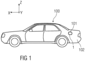
- FIG 1 shows a vehicle 100 with an opening 101 in a vehicle outer skin 102.
- the opening 101 is, for example, a tank opening or loading opening.
- the opening 101 is, for example, by means of a flap unit 1 covered, which is described in more detail below.
- the flap unit 1 can be installed in the area of the opening 101 in the outer skin 102 of the vehicle.
- a valve unit 1 is described below in a Cartesian coordinate system defined by three mutually perpendicular spatial directions.
- a longitudinal direction X is substantially horizontal to and preferably parallel to a longitudinal direction of the vehicle 100, which corresponds to the usual direction of travel of the vehicle 100.
- a transverse direction Y which runs perpendicular to the longitudinal direction X, is likewise oriented horizontally in the vehicle 100 and runs parallel to a transverse direction Y of the vehicle 100.
- a vertical direction Z runs perpendicular to the longitudinal direction X and perpendicular to the transverse direction Y.
- a vertical arrangement should be understood to mean an arrangement parallel to the vertical Z direction.
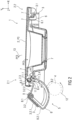
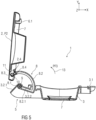
- figure 2 shows a schematic sectional view of a first embodiment of a flap unit 1 with a screen 2.
- the flap unit 1 comprises at least the screen 2 and a frame 3 .
- the screen 2 is arranged within a peripheral area of the frame 3 .
- the flap unit 1 is inserted with the frame 3 into the opening 101 in the vehicle outer skin 102 and fixed there.
- the frame 3 forms an edge of the opening 101, for example.
- figure 2 shows the screen 2 in a closed position P0, in which the screen 2 terminates flush with the frame 3 in particular.
- the panel 2 is used to cover an opening 101, in particular a loading opening or tank opening, of a vehicle 100, not shown that the panel 2 terminates flush with the frame 3 as well as flush with the outer skin 102 of the vehicle.
- the panel 2 is a movable panel 2 and is designed, for example, as a closure cover or a closure flap for the loading opening or tank opening.
- the panel 2 can be cup-shaped as shown.
- the aperture 2 can be disc-shaped. Facing away from the frame 3, the panel 2 has a surface shape that corresponds to a vehicle outer skin 102, in particular a largely flat or slightly curved shape.
- the aperture 2 is set up in such a way that it can be actuated and/or adjusted both electrically and manually.
- the aperture 2 can be adjusted electrically.
- An electric drive mechanism 4 is coupled, for example, to an adjusting mechanism 5 for the panel 2 and can be designed, for example, as a motor drive, in particular a spindle drive or a gear drive.
- the drive mechanism 4 and the adjustment mechanism 5 are arranged on a drive end 2.1 of the panel 2 and coupled to it.
- the screen On a holding end 2.2 of the screen 2 opposite the drive end 2.1, the screen is provided with a locking mechanism 6, for example a locking hook 6.1.
- the panel 2 can be releasably locked to the frame 3 by means of the locking mechanism 6 .
- the closure mechanism 6 is designed as a latching mechanism, in particular a positive latching connection. In the closed position P0 of the diaphragm 2, a counter bearing for the drive end 2.1 of the diaphragm 2 is thus formed on the holding end 2.2 of the diaphragm 2 facing away from the drive.
- the latching hook 6.1 engages, for example, in the closed position P0 of the panel 2 in an undercut 3.1 of the frame 3 in a releasably locking manner.
- the cover 2 is provided on the inside with a seal 7, for example a sealing ring, sealing lips and/or sealing strip.
- a seal 7 in the direction of the panel 2, in particular a sealing ring, sealing lips and/or sealing strip.
- the adjustment mechanism 5 can alternatively be coupled to a manual actuating mechanism for the panel 2, which is not shown in detail.
- a manual actuation mechanism is in particular coupled directly to the panel 2 and can be designed, for example, as a pressure actuation, in particular a so-called push-push mechanism, on the panel 2 .
- the shutter 2 can be moved both during an opening movement of the shutter 2 from the closed position P0 to an open position P2 (shown in Fig figure 5 ) as well as during a closing movement of the panel 2 from the open position P2 into the closed position P0 about a first axis of rotation 9, wherein the panel 2 can be pivoted about a second axis of rotation 10 relative to the adjustment mechanism 5 and at least partially translationally into a partially raised intermediate position P1 (shown in figure 3 ) is movable.
- the panel 2 When the panel 2 is moved from the partially raised intermediate position P1 to the open position P2 and vice versa, the panel 2 can be pivoted about the first axis of rotation 9 together with the adjustment mechanism 5 .
- the adjusting mechanism 5 can be designed as a double swivel joint 8 .
- the double swivel joint 8 comprises a first swivel joint 8.1, which is articulated to the frame 3 and is connected to a second swivel joint 8.3, which is articulated to the panel 2, via a connecting member 8.2.
- the adjusting mechanism 5 of the present panel 2 includes an additional joint, in particular the second pivot joint 8.3.
- the connecting member 8.2 is designed in particular as a pivoting lever, coupling lever or adjusting lever or pivoting arm, coupling arm or adjusting arm.
- the connecting member 8.2 is coupled on the one hand to the screen 2 and on the other hand is mounted on the frame 3 such that it can pivot about the first axis of rotation 9 by means of the first pivot joint 8.1.
- the panel 2 is pivotally mounted relative to the frame 3 by means of the pivotally mounted connecting member 8.2.
- the connecting link 8.2 can be made in one piece.
- the adjustment mechanism 5 has a joint socket 3.2 arranged on the frame 3 for the first pivot joint 8.1.
- the joint socket 3.2 is formed in the area of the drive end 2.1.
- the connecting link 8.2 is designed in section as a 2-legged, L-shaped, hook-shaped or arc-shaped pivoting lever.
- the connecting member 8.2 has the first rotary joint 8.1 on one end facing the frame 3, in particular the joint socket 3.2, and an adjusting pin 8.4 on one end facing the panel 2.
- the first rotary joint 8.1 is sleeve-shaped or cylindrical or spherical.
- Two stop arms 3.2.1 and 3.2.2 protrude from the joint socket 3.2 and serve as end stops for the adjusting mechanism 5 of the panel 2, in particular for the double swivel joint 8, for example for its connecting link 8.2.
- the stop arms 3.2.1 and 3.2.2 protrude from the socket 3.2 in such a way that the pivoting movement of the shutter 2 between the closed position P0 and the open position P2 (shown in Fig figure 5 ) is limited.
- at least one leg 8.2.1 of the connecting link 8.2 strikes the stop arm 3.2.1 (shown in Fig figure 2 ) and in the open position P2 on the stop arm 3.2.2 (shown in figure 5 ) at.
- the panel 2 also has an inner bearing element 2.3 for the second pivot joint 8.3.
- the panel 2 is pivotally mounted by means of the second pivot joint 8.3 about the second axis of rotation 10 relative to the frame 3 and to the connecting member 8.2.
- the panel 2 can be formed in one piece.
- the panel 2 can be made in several parts, in particular in two parts.
- a spring element 11 can be provided on the drive side, the drive end 2.1, of the panel 2, in particular in the area of the second pivot joint 8.3.
- the shutter 2 is held on the frame 3 in a prestressed manner in the closed position P0 by means of the spring element 11 .
- the greatest possible sealing pressure can be generated in the closed position P0 when the spring element 11 is tensioned, so that the screen 2 is flush with the frame 3 and is in sealing contact with the frame 3 by means of the seals 7.
- the spring element 11 is designed as a bistable torsion spring.
- the spring element 11 has two spring arms 11.1, 11.2. In the closed position P0 of the screen 2, the spring element 11 is tensioned. The spring force of the spring element 11 pulls the two spring arms 11.1 and 11.2 towards one another, as shown by the arrows PF1. As a result, both the aperture pin 2.4 and the adjustment pin 8.4 are subjected to an associated spring force of the relevant spring arm 11.1 or 11.2. As a result of this spring force of spring element 11, panel 2 is pulled in the direction of frame 3 according to arrow PF2, so that panel 2 rests against frame 3 in a form-fitting and sealing manner.
- first axis of rotation 9 of the first pivot joint 8.1 and the second axis of rotation 10 of the second pivot joint 8.3 are parallel arranged to each other.
- the axes of rotation 9, 10 can run vertically or horizontally depending on the opening direction of the panel 2, correspondingly horizontally or vertically.
- the axes of rotation 9, 10 run vertically and the panel 2 can be opened in the horizontal direction according to arrow PF3.
- the connecting link 8.2 in particular designed as an adjusting lever, pivoting lever or coupling lever, is configured in such a way that it moves on the first rotary joint 8.1 about its first axis of rotation 9 in a first arc 12.
- the panel 2, in particular a closure cover, is configured in such a way that it moves on the second rotary joint 8.3 about its second axis of rotation 10 in a second arc 13 according to arrow PF3.
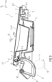
- the shutter 2 can be moved into the partially raised intermediate position P1, which is shown in figure 3 is shown.
- figure 3 shows a sectional view of the flap unit 1 with the screen 2 in the partially raised intermediate position P1, in which the screen 2 contacts the frame 3 at least in certain areas.
- the panel 2 can be positioned or positioned in relation to the frame 3 by means of the adjustment mechanism 5 in the partially raised intermediate position P1 in such a way that the drive end 2.1 of the panel 2 is raised and spaced from the frame 3 and the opposite drive-remote holding end 2.2 of the panel 2 with the frame 3 continues to be contacted, with the panel 2 already being unlocked.
- the latching hook 6.1 is disengaged from the undercut 3.1, which is designed as a latching projection on the frame 3, for example.
- the adjusting mechanism 5 is designed, for example, in such a way that it moves the panel 2 out of the plane of the frame 3, in particular initially pivots it into the raised intermediate position P1.
- the adjustment mechanism 5 is set up such that the panel 2 is first moved in the first arc 12 about the first axis of rotation 9, so that the drive end 2.1 is raised relative to the frame 3 and the vehicle outer skin 102 and the holding end 2.2 is unlocked.
- the opposite holding end 2.2 remains in contact with the frame 3.
- the flap unit 1 can be designed without a frame.
- the panel 2 continues to contact the vehicle outer skin 102 with its holding end 2.2.
- the spring element 11 relaxes, with the spring arm 11.2 being moved in the direction of the panel 2 according to the arrow PF4, so that the panel 2 pivots relative to the adjustment mechanism 5 about the second axis of rotation 10 in a second arc 13 according to the arrow PF3 and at least partially translationally according to the arrow PF5 is moved so that the drive end 2.1 of the panel 2 is raised and the panel 2 is unlocked, in particular the latching hook 6.1 disengages from the undercut 3.1.
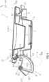
- figure 4 shows a sectional view of the flap unit 1 with the screen 2 in a completely raised intermediate position P1.1, in particular completely spaced apart from the frame 3, in which the holding end 2.2 of the screen 2 no longer makes contact with the frame 3.
- the panel 2 reaches this fully raised intermediate position P1.1 by further movement of the adjustment mechanism 5, in particular of the connecting member 8.2, about the first axis of rotation 9 according to arrow PF6.
- the screen 2 is pivoted about the first axis of rotation 9 together with the connecting member 8.2.
- the spring element 11 remains relaxed.
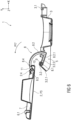
- figure 5 shows a sectional view of the flap unit 1 with the panel 2 in the open position P2.
- the screen 2 is positioned largely perpendicular to the frame 3.
- the spring element 11 remains relaxed.
- the Aperture 2 has been pivoted together with the adjusting mechanism 5 about the first axis of rotation 9 according to arrow PF 3 into the open position P2.
- figure 6 shows a sectional view of the flap unit 1 with the panel 2 in a misuse position P3.
- the diaphragm 2 was manually actuated, in particular pivoted, relative to the adjustment mechanism 5 about the second axis of rotation 10 according to arrow PF7.
- the adjusting mechanism 5 is fixed due to the impact of the leg 8.2.1 on the stop arm 3.2.2 of the frame 3.
- the panel 2 can thus be pivoted about the second axis of rotation 10 relative to the frame 3 and to the adjustment mechanism 5 by means of the second rotary joint 8.3.
- the spring element 11 is tensioned in that the diaphragm pin 2.4 entrains the corresponding spring arm 11.1 during the pivoting movement of the diaphragm 2 according to arrow PF7. If the shutter 2 is no longer actuated, then due to the relaxation of the spring element 11 it is automatically returned to the open position P2 and further until the spring element 11 is relaxed.
- figure 7 shows a sectional view of the flap unit 1 with the panel 2 during a closing movement of the panel 2 as a result of the relaxation of the spring element 11 according to arrow PF8.
Landscapes
- Engineering & Computer Science (AREA)
- Life Sciences & Earth Sciences (AREA)
- Sustainable Development (AREA)
- Sustainable Energy (AREA)
- Chemical & Material Sciences (AREA)
- Combustion & Propulsion (AREA)
- Transportation (AREA)
- Mechanical Engineering (AREA)
- Cooling, Air Intake And Gas Exhaust, And Fuel Tank Arrangements In Propulsion Units (AREA)
- Power-Operated Mechanisms For Wings (AREA)
- Specific Sealing Or Ventilating Devices For Doors And Windows (AREA)
- Superstructure Of Vehicle (AREA)
Abstract
Die Erfindung betrifft eine Klappeneinheit (1) zur Abdeckung einer Öffnung (101), insbesondere eine Ladeöffnung oder Tanköffnung, eines Fahrzeugs (100), wobei die Klappeneinheit (1) zumindest:- einen Rahmen (3), und- eine bewegbare Blende (2) umfasst, die innerhalb eines Umfangsbereichs des Rahmens (3) angeordnet ist,wobei die Blende (2) zwischen einer geschlossenen Position (P0), in welcher die Blende (2) bündig mit dem Rahmen (3) abschließt und gehalten ist, und einer geöffneten Position (P2) bewegbar ist, undwobei die Blende (2) sowohl bei einer Öffnungsbewegung aus der geschlossenen Position (P0), als auch bei einer Schließbewegung aus der geöffneten Position (P2), in eine teilweise angehobene Zwischenposition (P1) bewegbar ist.The invention relates to a flap unit (1) for covering an opening (101), in particular a loading opening or tank opening, of a vehicle (100), the flap unit (1) having at least: - a frame (3), and - a movable panel (2 ) disposed within a peripheral region of the frame (3), the shade (2) being held between a closed position (P0) in which the shade (2) is flush with the frame (3) and a open position (P2), and wherein the screen (2) is movable in both opening movement from the closed position (P0) and closing movement from the open position (P2) to an intermediate partially raised position (P1).
Description
Die Erfindung betrifft eine Klappeneinheit zur Abdeckung einer Öffnung, insbesondere einer Ladeöffnung oder Tanköffnung an einem Fahrzeug. Des Weiteren betrifft die Erfindung ein Fahrzeug mit einer solchen Klappeneinheit.The invention relates to a flap unit for covering an opening, in particular a loading opening or tank opening on a vehicle. Furthermore, the invention relates to a vehicle with such a flap unit.
An Fahrzeugen werden Öffnungen in der Fahrzeugkarosserie, wie zum Beispiel eine Ladeöffnung oder Tanköffnung, mittels einer Blende oder Klappe (auch Verschlussdeckel genannt) verschlossen, um eine Verschmutzung und einen Missbrauch zu verhindern. Klappen sind beispielsweise aus der
Aufgabe der vorliegenden Erfindung ist es, eine Klappeneinheit zur Abdeckung einer Öffnung an einem Fahrzeug bereitzustellen, welche einfach aufgebaut und einfach zu bedienen ist. Insbesondere soll eine Klappeneinheit angegeben werden, welche auch bei einer großen, insbesondere langen, Blende hinreichend dicht in einer geschlossenen Stellung gehalten ist. Des Weiteren ist es Aufgabe der Erfindung, ein Fahrzeug mit einer verbesserten Klappeneinheit anzugeben.The object of the present invention is to provide a flap unit for covering an opening in a vehicle, which is simple in construction and easy to operate. In particular, a flap unit is to be specified which is held sufficiently tightly in a closed position even with a large, in particular long, screen. Furthermore, it is the object of the invention to specify a vehicle with an improved flap unit.
Die erstgenannte Aufgabe wird erfindungsgemäß gelöst durch eine Klappeneinheit mit den Merkmalen des Patentanspruchs 1. Hinsichtlich des Fahrzeugs wird die Aufgabe erfindungsgemäß mit den Merkmalen des Patentanspruchs 10 gelöst.The first-mentioned object is achieved according to the invention by a flap unit having the features of
Vorteilhafte Weiterbildungen sind Gegenstand der abhängigen Patentansprüche.Advantageous developments are the subject matter of the dependent patent claims.
Die erfindungsgemäße Klappeneinheit zur Abdeckung einer Öffnung, insbesondere eine Ladeöffnung oder Tanköffnung, eines Fahrzeugs, umfasst zumindest einen Rahmen und eine Blende, zum Beispiel einen Verschlussdeckel oder eine Verschlussklappe, die an dem Rahmen mittels eines Verstellmechanismus bewegbar angeordnet ist, wobei die Blende zwischen einer geschlossenen Position und einer geöffneten Position bewegbar ist, und wobei sowohl bei einer Öffnungsbewegung der Blende aus der geschlossenen Position in die geöffnete Position als auch bei einer Schließbewegung der Blende aus der geöffneten Position in die geschlossene Position der Verstellmechanismus um eine erste Drehachse schwenkbar ist und die Blende gegenüber dem Verstellmechanismus um eine zweite Drehachse schwenkbar und zumindest anteilig translatorisch in eine, insbesondere teilweise, angehobene Zwischenposition bewegbar ist. Die Blende ist dabei insbesondere derart kombiniert schwenk- und anteilig translatorisch in die angehobene Zwischenposition bewegbar, dass die Blende entriegelt ist.The flap unit according to the invention for covering an opening, in particular a loading opening or tank opening, of a vehicle comprises at least one frame and a cover, for example a closure cover or a closure flap, which is attached to the frame by means of an adjustment mechanism is movably arranged, wherein the panel is movable between a closed position and an open position, and wherein both during an opening movement of the panel from the closed position to the open position and during a closing movement of the panel from the open position to the closed position of the The adjustment mechanism is pivotable about a first axis of rotation and the panel can be pivoted relative to the adjustment mechanism about a second axis of rotation and can be moved at least partially translationally into an, in particular partially, raised intermediate position. The panel can in particular be moved in a combined pivoting and partially translational manner into the raised intermediate position in such a way that the panel is unlocked.
Die Blende ist derart eingerichtet, dass diese sowohl elektrisch als auch manuell betätigt werden kann.The aperture is set up in such a way that it can be operated both electrically and manually.
Die mit der Erfindung erzielten Vorteile bestehen insbesondere darin, dass mittels der teilweise angehobenen Zwischenposition der Blende zum Beispiel bei der Schließbewegung zunächst ein antriebsabgewandtes Halteende der Blende mit dem Rahmen kontaktiert, so dass bei einer weiteren Schließbewegung dieses antriebsabgewandte Halteende der Blende formschlüssig in die geschlossene, insbesondere verriegelnde, Position gebracht werden kann und sich danach ein Antriebsende der Blende flächenbündig und dichtend an den Rahmen legt. Somit ist eine höhere Dichtungskraft der Blende am Rahmen ermöglicht, da auf dem Antriebsende die Antriebskraft, insbesondere eine Motorkraft, wirkt und auf dem antriebsabgewandten Halteende der Blende ein Gegenlager gebildet ist.The advantages achieved with the invention are, in particular, that by means of the partially raised intermediate position of the panel, for example during the closing movement, a holding end of the panel facing away from the drive first makes contact with the frame, so that during a further closing movement this holding end of the panel facing away from the drive can be positively locked into the closed, in particular locking, position can be brought and then a drive end of the panel is flush and sealingly against the frame. This enables a higher sealing force of the panel on the frame, since the driving force, in particular a motor force, acts on the drive end and a counter bearing is formed on the holding end of the panel facing away from the drive.
Darüber hinaus ermöglicht eine solche Klappeneinheit mit Antriebsende oder Antriebsseite und verriegelndem Gegenlager auf dem antriebsabgewandten Halteende der Blende eine erhöhte Sicherheit gegen Vandalismus, da die Blende auf beiden Seiten beziehungsweise Enden formschlüssig anliegt und verriegelt wird. Darüber hinaus ist eine flächenbündige Ausrichtung der Blende am Rahmen mittels eines keilförmigen Hinterschnitts am antriebsabgewandten Halteende der Blende ermöglicht.In addition, such a flap unit with a drive end or drive side and a locking counter bearing on the drive-remote holding end of the panel allows increased security against vandalism, since the panel abuts positively on both sides or ends and is locked. In addition, a flush alignment of the panel on the frame is made possible by means of a wedge-shaped undercut on the holding end of the panel facing away from the drive.
Bei einer Öffnungsbewegung der Blende hingegen ermöglicht die angehobene Zwischenposition, dass das Antriebsende der Blende zunächst angehoben wird und das antriebsabgewandte Halteende erst später geöffnet, insbesondere nach außen in die geöffnete Position geschwenkt, wird. Hierdurch ist eine Eisaufbrechkraft erhöht. Beispielsweise wird dies durch einen Vorlauf auf dem Antriebsende, welches zuerst in die Zwischenposition angehoben wird, ermöglicht, wobei das antriebsabgewandte Halteende der Blende weiterhin mit dem Rahmen kontaktiert. Somit ist die Blende nicht starr am Rahmen angebunden und wird nicht zeitgleich und parallel vom Rahmen entfernt.On the other hand, during an opening movement of the panel, the raised intermediate position allows the drive end of the panel to be raised first and the holding end facing away from the drive to be opened later, in particular pivoted outwards into the open position. As a result, an ice breaking force is increased. For example, this is made possible by a fore-run on the drive end, which is first raised to the intermediate position, with the non-driven retaining end of the bezel still contacting the frame. Thus, the screen is not rigidly attached to the frame and is not removed from the frame at the same time and in parallel.
Ein weiterer Aspekt sieht vor, dass beim Bewegen der Blende von der angehobenen Zwischenposition in die geöffnete Position und umgekehrt die Blende gemeinsam mit dem Verstellmechanismus um die erste Drehachse schwenkbar ist. Hierbei wird die Blende relativ zum Rahmen und beispielsweise zu einer Fahrzeugaußenhaut, in welcher der Rahmen montiert ist, bewegt und dabei geöffnet oder geschlossen.A further aspect provides that when the panel is moved from the raised intermediate position to the open position and vice versa, the panel can be pivoted about the first axis of rotation together with the adjustment mechanism. In this case, the panel is moved relative to the frame and, for example, to a vehicle outer skin in which the frame is mounted, and is thereby opened or closed.
Eine Weiterbildung sieht vor, dass der Verstellmechanismus zwischen Blende und Rahmen angeordnet ist. Insbesondere ist der Verstellmechanismus an dem Antriebsende der bewegbaren Blende zwischen Blende und Rahmen angeordnet.A further development provides that the adjustment mechanism is arranged between the panel and the frame. In particular, the adjusting mechanism is arranged at the drive end of the movable panel between the panel and the frame.
Insbesondere ist die Blende mittels des Verstellmechanismus in der teilweise gespannten angehobenen Zwischenposition derart zum Rahmen positionierbar, dass das Antriebsende der Blende anhebbar oder angehoben ist, insbesondere zum Rahmen hin beabstandet anhebbar oder angehoben ist, und das gegenüberliegende antriebsabgewandte Ende der Blende mit dem Rahmen kontaktiert.In particular, the panel can be positioned by means of the adjustment mechanism in the partially tensioned, raised intermediate position relative to the frame in such a way that the drive end of the panel can be raised or raised, in particular can be raised or raised at a distance from the frame, and the opposite end of the panel facing away from the drive makes contact with the frame.
Ein weiteres Ausführungsbeispiel sieht vor, dass die Blende an dem Halteende, insbesondere auf der antriebsabgewandten Seite der Blende, mittels eines Verschlussmechanismus am Rahmen lösbar verriegelbar ist. Beispielsweise ist der Verschlussmechanismus als ein Rastmechanismus, insbesondere eine formschlüssige Rastverbindung, ausgebildet. In der geschlossenen Position der Blende ist somit an dem antriebsabgewandten Halteende der Blende ein Gegenlager für das Antriebsende der Blende gegeben.A further exemplary embodiment provides that the panel can be releasably locked on the holding end, in particular on the side of the panel facing away from the drive, by means of a locking mechanism on the frame. For example, the closure mechanism is designed as a latching mechanism, in particular a positive latching connection. In the closed position of the Abutment for the drive end of the diaphragm is thus provided on the holding end of the diaphragm facing away from the drive.
In einem weiteren Ausführungsbeispiel umfasst der Verstellmechanismus ein Doppeldrehgelenk. Beispielsweise umfasst das Doppeldrehgelenk ein erstes Drehgelenk, welches an dem Rahmen angelenkt ist, und über ein Verbindungsglied mit einem zweiten Drehgelenk verbunden ist, welches an der Blende angelenkt ist. Mit anderen Worten: Gegenüber einer herkömmlichen Verstellvorrichtung für eine Blende umfasst der Verstellmechanismus der vorliegenden Blende ein zusätzliches Drehgelenk. Das Verbindungsglied ist insbesondere als ein Schwenkhebel, Koppelhebel oder Verstellhebel oder Schwenkarm, Koppelarm oder Verstellarm ausgebildet.In a further exemplary embodiment, the adjustment mechanism comprises a double swivel joint. For example, the double pivot joint comprises a first pivot joint, which is pivoted on the frame, and is connected via a connecting link to a second pivot joint, which is pivoted on the panel. In other words: Compared to a conventional adjustment device for a panel, the adjustment mechanism of the present panel includes an additional rotary joint. The connecting member is designed in particular as a pivoting lever, coupling lever or adjusting lever or pivoting arm, coupling arm or adjusting arm.
Das Verbindungsglied, insbesondere der Verstellhebel, ist einerseits mit der Blende gekoppelt und andererseits an dem Rahmen um die erste Drehachse mittels des ersten Drehgelenks schwenkbar gelagert. Der Verstellhebel ist beispielsweise derart ausgebildet, dass dieser die Blende aus der Ebene des Rahmens bewegt, insbesondere zunächst in die angehobene Zwischenposition schwenkt und hebt und anschließend in die geöffnete Position schwenkt.The connecting member, in particular the adjusting lever, is coupled to the panel on the one hand and is mounted on the frame on the other hand so that it can pivot about the first axis of rotation by means of the first pivot joint. The adjusting lever is designed, for example, in such a way that it moves the panel out of the plane of the frame, in particular initially pivots and lifts it into the raised intermediate position and then pivots it into the open position.
Dabei kann der Verstellhebel einteilig ausgebildet sein. Der Verstellmechanismus weist eine am Rahmen angeordnete Gelenkpfanne für das erste Drehgelenk auf. Die Blende umfasst darüber hinaus ein inneres Lagerelement für das zweite Drehgelenk.The adjusting lever can be designed in one piece. The adjustment mechanism has a joint socket arranged on the frame for the first pivot joint. The bezel also includes an inner bearing member for the second pivot.
Die Blende kann in einer möglichen Ausführungsform einteilig ausgebildet sein. Alternativ kann die Blende mehrteilig, insbesondere zweigeteilt, ausgebildet sein.In one possible embodiment, the screen can be formed in one piece. Alternatively, the panel can be made in several parts, in particular in two parts.
Die Betätigung und/oder Verstellung der Blende kann manuell, zum Beispiel mittels Druckbetätigung und manueller Verstellbewegung, oder elektrisch, zum Beispiel mittels einer elektrisch bewegbaren Blende, erfolgen.The panel can be actuated and/or adjusted manually, for example by means of pressure actuation and manual adjustment movement, or electrically, for example by means of an electrically movable panel.
Der Verstellmechanismus kann beispielsweise mit einem Betätigungsmechanismus für die Blende gekoppelt sein. Ein elektrischer Betätigungsmechanismus ist direkt mit dem Verstellmechanismus gekoppelt und kann beispielsweise als ein Motorantrieb, insbesondere ein Spindelantrieb oder Zahnradantrieb, ausgebildet sein. Ein manueller Betätigungsmechanismus ist direkt mit der Blende gekoppelt und kann beispielsweise als eine Druckbetätigung, insbesondere eine sogenannte Push-Push-Mechanik, ausgebildet sein.The adjustment mechanism can, for example, be coupled to an actuating mechanism for the diaphragm. An electrical actuation mechanism is coupled directly to the adjustment mechanism and can be designed, for example, as a motor drive, in particular a spindle drive or a gear drive. A manual actuation mechanism is coupled directly to the panel and can be designed, for example, as a pressure actuation, in particular a so-called push-push mechanism.
Zusätzlich kann insbesondere an dem Antriebsende der Blende, insbesondere im Bereich des zweiten Drehgelenks, ein Federelement vorgesehen sein, mittels dessen die Blende in Richtung des Rahmens gespannt in der geschlossenen Position gehalten ist. Insbesondere bei einer großflächigen Blende kann bei gespannter Feder in der geschlossenen Position ein größtmöglicher Dichtungsdruck erzeugt werden, so dass die Blende bündig mit dem Rahmen abschließt und dichtend am Rahmen anliegt. Beispielsweise ist das Federelement als eine bistabile Schenkelfeder ausgebildet.In addition, a spring element can be provided in particular on the drive end of the panel, in particular in the area of the second pivot joint, by means of which the panel is held tensioned in the closed position in the direction of the frame. Particularly in the case of a large-area panel, the greatest possible sealing pressure can be generated when the spring is tensioned in the closed position, so that the panel is flush with the frame and rests against the frame in a sealing manner. For example, the spring element is designed as a bistable torsion spring.
In einem einfachen Ausführungsbeispiel sind die Drehachsen des ersten Drehgelenks und des zweiten Drehgelenks parallel zueinander angeordnet. Dabei können je nach Öffnungssinn der Blende, vertikal oder horizontal öffnend, die Drehachsen entsprechend horizontal beziehungsweise vertikal verlaufen.In a simple embodiment, the axes of rotation of the first pivot joint and the second pivot joint are arranged parallel to one another. Depending on the opening direction of the panel, vertically or horizontally opening, the axes of rotation can run horizontally or vertically accordingly.
Das Verbindungsglied, insbesondere ausgebildet als ein Verstellhebel, Schwenkhebel oder Koppelhebel, ist derart konfiguriert, dass es sich an dem ersten Drehgelenk um die erste Drehachse in einem ersten Bogen bewegt. Die Blende, insbesondere ein Verschlussdeckel, ist derart konfiguriert, dass sie sich an dem zweiten Drehgelenk um die zweite Drehachse in einem zweiten Bogen bewegt.The connecting member, in particular designed as an adjustment lever, pivoted lever or coupling lever, is configured in such a way that it moves on the first pivot joint about the first axis of rotation in a first arc. The screen, in particular a closure cover, is configured in such a way that it moves at the second pivot joint about the second axis of rotation in a second arc.
Ein erfindungsgemäßes Fahrzeug umfasst eine Öffnung, insbesondere eine Ladeöffnung oder Tanköffnung, und die zuvor beschriebene Klappeneinheit zum Abdecken der Öffnung.A vehicle according to the invention comprises an opening, in particular a loading opening or tank opening, and the flap unit described above for covering the opening.
Ausführungsbeispiele der Erfindung werden anhand von Zeichnungen näher erläutert. Dabei zeigen:
Figur 1- ein Fahrzeug mit einer Öffnung und einer Klappeneinheit zum Abdecken der Öffnung,
Figur 2- eine Schnittdarstellung einer Klappeneinheit mit einer Blende in einer geschlossenen Position,
Figur 3- eine Schnittdarstellung einer Klappeneinheit mit einer Blende in einer angehobenen Zwischenposition, in welcher die Blende zumindest bereichsweise mit dem Rahmen kontaktiert,
Figur 4- eine Schnittdarstellung einer Klappeneinheit mit einer Blende in einer angehobenen und zum Rahmen beabstandete Zwischenposition,
Figur 5- eine Schnittdarstellung einer Klappeneinheit mit einer Blende in einer geöffneten Position,
Figur 6- eine Schnittdarstellung einer Klappeneinheit mit einer Blende in einer Missbrauchsposition, und
Figur 7- eine Schnittdarstellung einer Klappeneinheit mit einer Blende in einer Schließbewegung.
- figure 1
- a vehicle with an opening and a flap unit for covering the opening,
- figure 2
- a sectional view of a flap unit with a panel in a closed position,
- figure 3
- a sectional view of a flap unit with a panel in a raised intermediate position, in which the panel at least partially contacts the frame,
- figure 4
- a sectional view of a flap unit with a panel in a raised intermediate position spaced apart from the frame,
- figure 5
- a sectional view of a flap unit with a panel in an open position,
- figure 6
- a sectional view of a valve assembly with a bezel in an abuse position, and
- figure 7
- a sectional view of a flap unit with a panel in a closing movement.
Einander entsprechende Teile sind in allen Figuren mit den gleichen Bezugszeichen versehen.Corresponding parts are provided with the same reference symbols in all figures.
Unter Bezugnahme auf die Zeichnungen ist nachstehend eine Klappeneinheit 1 in einem kartesischen Koordinatensystem beschrieben, das durch drei zueinander senkrechte räumliche Richtungen definiert ist. Wenn die Klappeneinheit 1 in dem Fahrzeug 100 installiert ist, verläuft eine Längsrichtung X im Wesentlichen horizontal zu und vorzugsweise parallel mit einer Längsrichtung des Fahrzeugs 100, die der gewöhnlichen Fahrtrichtung des Fahrzeugs 100 entspricht. Eine Querrichtung Y, die senkrecht zu der Längsrichtung X verläuft, ist gleichermaßen horizontal im Fahrzeug 100 orientiert und verläuft parallel zu einer Querrichtung Y des Fahrzeugs 100. Eine vertikale Richtung Z verläuft senkrecht zu der Längsrichtung X und senkrecht zu der Querrichtung Y. Eine vertikale Anordnung sollte so verstanden werden, dass damit eine Anordnung gemeint ist, die parallel zu der vertikalen Richtung Z verläuft.With reference to the drawings, a
Die Klappeneinheit 1 umfasst zumindest die Blende 2 und einen Rahmen 3. Die Blende 2 ist innerhalb eines Umfangsbereichs des Rahmens 3 angeordnet. Die Klappeneinheit 1 ist mit dem Rahmen 3 in die Öffnung 101 in der Fahrzeugaußenhaut 102 eingesetzt und dort fixiert. Der Rahmen 3 bildet beispielsweise einen Rand der Öffnung 101 aus.The
Die Blende 2 ist eine bewegbare Blende 2 und zum Beispiel als ein Verschlussdeckel oder eine Verschlussklappe für die Ladeöffnung oder Tanköffnung ausgebildet. Die Blende 2 kann wie dargestellt topfförmig ausgebildet sein. Alternativ kann die Blende 2 scheibenförmig ausgebildet sein. Vom Rahmen 3 weggewandt weist die Blende 2 eine mit einer Fahrzeugaußenhaut 102 korrespondierende Oberflächenform, insbesondere eine weitgehend ebene oder leicht gewölbte Form, auf.The
Die Blende 2 ist derart eingerichtet, dass diese sowohl elektrisch als auch manuell betätigt und/oder verstellt werden kann.The
Die Verstellung der Blende 2 kann elektrisch erfolgen. Ein elektrischer Antriebsmechanismus 4 ist zum Beispiel mit einem Verstellmechanismus 5 für die Blende 2 gekoppelt und kann beispielsweise als ein Motorantrieb, insbesondere ein Spindelantrieb oder Zahnradantrieb, ausgebildet sein. Der Antriebsmechanismus 4 und der Verstellmechanismus 5 sind an einem Antriebsende 2.1 der Blende 2 angeordnet und mit dieser gekoppelt.The
An einem dem Antriebsende 2.1 gegenüberliegenden Halteende 2.2 der Blende 2 ist diese mit einem Verschlussmechanismus 6, zum Beispiel einem Rasthaken 6.1, versehen. Die Blende 2 ist mittels des Verschlussmechanismus 6 am Rahmen 3 lösbar verriegelbar ist. Beispielsweise ist der Verschlussmechanismus 6 als ein Rastmechanismus, insbesondere eine formschlüssige Rastverbindung, ausgebildet. In der geschlossenen Position P0 der Blende 2 ist somit auf dem antriebsabgewandten Halteende 2.2 der Blende 2 ein Gegenlager für das Antriebsende 2.1 der Blende 2 gebildet.On a holding end 2.2 of the
Der Rasthaken 6.1 greift beispielsweise in der geschlossenen Position P0 der Blende 2 in einen Hinterschnitt 3.1 des Rahmens 3 lösbar verriegelnd ein.The latching hook 6.1 engages, for example, in the closed position P0 of the
Die Blende 2 ist in Richtung des Rahmens 3 innenseitig mit einer Dichtung 7, zum Beispiel einem Dichtungsring, Dichtungslippen und/oder Dichtungsstrang, versehen. Zusätzlich oder alternativ kann der Rahmen 3 in Richtung der Blende 2 mit einer Dichtung 7, insbesondere einem Dichtungsring, Dichtungslippen und/oder Dichtungsstrang, versehen sein.In the direction of the
Der Verstellmechanismus 5 kann alternativ mit einem manuellen, nicht näher dargestellten Betätigungsmechanismus für die Blende 2 gekoppelt sein. Ein solcher manueller Betätigungsmechanismus ist insbesondere direkt mit der Blende 2 gekoppelt und kann beispielsweise als eine Druckbetätigung, insbesondere eine sogenannte Push-Push-Mechanik, an der Blende 2 ausgebildet sein.The
Mittels des Verstellmechanismus 5 ist die Blende 2 sowohl bei einer Öffnungsbewegung der Blende 2 aus der geschlossenen Position P0 in eine geöffnete Position P2 (dargestellt in
Beim Bewegen der Blende 2 von der teilweise angehobenen Zwischenposition P1 in die geöffnete Position P2 und umgekehrt ist die Blende 2 gemeinsam mit dem Verstellmechanismus 5 um die erste Drehachse 9 schwenkbar.When the
Der Verstellmechanismus 5 kann als ein Doppeldrehgelenk 8 ausgebildet sein. Beispielsweise umfasst das Doppeldrehgelenk 8 ein erstes Drehgelenk 8.1, welches an dem Rahmen 3 angelenkt ist, und über ein Verbindungsglied 8.2 mit einem zweiten Drehgelenk 8.3 verbunden ist, welches an der Blende 2 angelenkt ist.The
Gegenüber einer herkömmlichen Verstellvorrichtung für eine Blende 2 umfasst der Verstellmechanismus 5 der vorliegenden Blende 2 ein zusätzliches Gelenk, insbesondere das zweite Drehgelenk 8.3.Compared to a conventional adjusting device for a
Das Verbindungsglied 8.2 ist insbesondere als ein Schwenkhebel, Koppelhebel oder Verstellhebel oder Schwenkarm, Koppelarm oder Verstellarm ausgebildet.The connecting member 8.2 is designed in particular as a pivoting lever, coupling lever or adjusting lever or pivoting arm, coupling arm or adjusting arm.
Das Verbindungsglied 8.2 ist einerseits mit der Blende 2 gekoppelt und andererseits an dem Rahmen 3 um die erste Drehachse 9 mittels des ersten Drehgelenks 8.1 schwenkbar gelagert. Die Blende 2 ist mittels des schwenkbar gelagerten Verbindungsglieds 8.2 relativ zum Rahmen 3 schwenkbar gelagert.The connecting member 8.2 is coupled on the one hand to the
Das Verbindungsglied 8.2 kann einteilig ausgebildet sein. Der Verstellmechanismus 5 weist eine am Rahmen 3 angeordnete Gelenkpfanne 3.2 für das erste Drehgelenk 8.1 auf. Die Gelenkpfanne 3.2 ist im Bereich des Antriebsende 2.1 ausgebildet. Das Verbindungsglied 8.2 ist im Schnitt als ein 2-schenkliger, L-förmiger, hakenförmiger oder bogenförmiger Schwenkhebel ausgebildet. Das Verbindungsglied 8.2 weist an einem dem Rahmen 3, insbesondere der Gelenkpfanne 3.2, zugewandten Ende das erste Drehgelenk 8.1 und an einem der Blende 2 zugewandten Ende einen Verstellzapfen 8.4 auf. Das erste Drehgelenk 8.1 ist hülsenförmig oder zylindrisch oder kugelförmig ausgebildet.The connecting link 8.2 can be made in one piece. The
Von der Gelenkpfanne 3.2 stehen zwei Anschlagsarme 3.2.1 und 3.2.2 ab, welche als Endanschläge für den Verstellmechanismus 5 der Blende 2, insbesondere für das Doppeldrehgelenk 8, beispielsweise für dessen Verbindungsglied 8.2, dienen. Die Anschlagsarme 3.2.1 und 3.2.2 stehen derart von der Gelenkpfanne 3.2 ab, dass die Schwenkbewegung der Blende 2 zwischen der geschlossenen Position P0 und der geöffneten Position P2 (dargestellt in
Die Blende 2 weist darüber hinaus ein inneres Lagerelement 2.3 für das zweite Drehgelenk 8.3 auf. Die Blende 2 ist mittels des zweiten Drehgelenks 8.3 um die zweite Drehachse 10 relativ zum Rahmen 3 und zum Verbindungsglied 8.2 schwenkbar gelagert.The
Die Blende 2 kann in einer möglichen Ausführungsform einteilig ausgebildet sein. Alternativ kann die Blende 2 mehrteilig, insbesondere zweigeteilt, ausgebildet sein.In one possible embodiment, the
Zusätzlich kann auf der Antriebsseite, dem Antriebsende 2.1, der Blende 2, insbesondere im Bereich des zweiten Drehgelenks 8.3, ein Federelement 11 vorgesehen sein. Mittels des Federelements 11 ist die Blende 2 vorgespannt in der geschlossenen Position P0 an dem Rahmen 3 gehalten.In addition, a
Insbesondere bei einer großflächigen Blende 2 kann in der geschlossenen Position P0 bei gespanntem Federelement 11 ein größtmöglicher Dichtungsdruck erzeugt werden, so dass die Blende 2 bündig mit dem Rahmen 3 abschließt und mittels der Dichtungen 7 dichtend am Rahmen 3 anliegt. Beispielsweise ist das Federelement 11 als eine bistabile Schenkelfeder ausgebildet.Particularly in the case of a large-
Das Federelement 11 weist zwei Federarme 11.1, 11.2 auf. In der geschlossenen Position P0 der Blende 2 ist das Federelement 11 gespannt. Die Federkraft des Federelements 11 zieht die beiden Federarme 11.1 und 11.2 zueinander, wie anhand der Pfeile PF1 gezeigt. Hierdurch werden sowohl der Blendenzapfen 2.4 als auch der Verstellzapfen 8.4 mit einer zugehörigen Federkraft des betreffenden Federarms 11.1 beziehungsweise 11.2 beaufschlagt. Infolge dieser Federkraft des Federelements 11 wird die Blende 2 gemäß Pfeil PF2 in Richtung des Rahmens 3 gezogen, so dass die Blende 2 formschlüssig und dichtend an dem Rahmen 3 anliegt.The
In einem einfachen Ausführungsbeispiel sind die erste Drehachse 9 des ersten Drehgelenks 8.1 und die zweite Drehachse 10 des zweiten Drehgelenks 8.3 parallel zueinander angeordnet. Dabei können die Drehachsen 9, 10 je nach Öffnungssinn der Blende 2, vertikal oder horizontal öffnend, entsprechend horizontal beziehungsweise vertikal verlaufen. Im Ausführungsbeispiel verlaufen die Drehachsen 9, 10 vertikal und die Blende 2 kann in horizontaler Richtung gemäß Pfeil PF3 geöffnet werden.In a simple exemplary embodiment, the first axis of
Das Verbindungsglied 8.2, insbesondere ausgebildet als ein Verstellhebel, Schwenkhebel oder Koppelhebel, ist derart konfiguriert, dass es sich an dem ersten Drehgelenk 8.1 um dessen erste Drehachse 9 in einem ersten Bogen 12 bewegt. Die Blende 2, insbesondere ein Verschlussdeckel, ist derart konfiguriert, dass er sich an dem zweiten Drehgelenk 8.3 um dessen zweite Drehachse 10 in einem zweiten Bogen 13 gemäß Pfeil PF3 bewegt.The connecting link 8.2, in particular designed as an adjusting lever, pivoting lever or coupling lever, is configured in such a way that it moves on the first rotary joint 8.1 about its first axis of
Sowohl bei einer Öffnungsbewegung aus der geschlossenen Position P0 der Blende 2 als auch bei einer Schließbewegung aus der geöffneten Position P2 der Blende 2 ist die Blende 2 jeweils in die teilweise angehobene Zwischenposition P1 bewegbar, die in
Insbesondere ist die Blende 2 mittels des Verstellmechanismus 5 in der teilweise angehobenen Zwischenposition P1 derart zum Rahmen 3 positionierbar oder positioniert, dass das Antriebsende 2.1 der Blende 2 angehoben und von dem Rahmen 3 beabstandet ist und das gegenüberliegende antriebsabgewandte Halteende 2.2 der Blende 2 mit dem Rahmen 3 weiterhin kontaktiert, wobei die Blende 2 bereits entriegelt ist. Der Rasthaken 6.1 ist außer Eingriff von dem Hinterschnitt 3.1 gelangt, der beispielsweise als ein Rastvorsprung am Rahmen 3 ausgebildet ist.In particular, the
Der Verstellmechanismus 5 ist beispielsweise derart ausgebildet, dass dieser die Blende 2 aus der Ebene des Rahmens 3 bewegt, insbesondere zunächst in die angehobene Zwischenposition P1 schwenkt. Beispielsweise ist der Verstellmechanismus 5 derart eingerichtet, dass die Blende 2 zunächst in dem ersten Bogen 12 um die erste Drehachse 9 bewegt wird, so dass das Antriebsende 2.1 gegenüber dem Rahmen 3 und der Fahrzeugaußenhaut 102 angehoben wird und das Halteende 2.2 entriegelt wird. Dabei bleibt das gegenüber liegende Halteende 2.2 weiterhin in Kontakt mit dem Rahmen 3. Alternativ kann die Klappeneinheit 1 rahmenlos ausgebildet sein. In einem solchen alternativen Ausführungsbeispiel kontaktiert die Blende 2 mit ihrem Halteende 2.2 weiterhin die Fahrzeugaußenhaut 102.The
Zusätzlich entspannt das Federelement 11, wobei der Federarm 11.2 in Richtung der Blende 2 gemäß Pfeil PF4 bewegt wird, so dass die Blende 2 relativ zum Verstellmechanismus 5 um die zweite Drehachse 10 in einem zweiten Bogen 13 gemäß Pfeil PF3 schwenkt und zumindest anteilig translatorisch gemäß Pfeil PF5 bewegt wird, so dass das Antriebsende 2.1 der Blende 2 angehoben und die Blende 2 entriegelt wird, insbesondere der Rasthaken 6.1 außer Eingriff vom Hinterschnitt 3.1 gelangt.In addition, the
- 11
- Klappeneinheitflap unit
- 22
- Blendecover
- 2.12.1
- Antriebsendedrive end
- 2.22.2
- Halteendeholding end
- 2.32.3
- Lagerelementbearing element
- 2.42.4
- Blendenzapfenaperture pivot
- 33
- RahmenFrame
- 3.13.1
- Hinterschnittundercut
- 3.23.2
- Gelenkpfannesocket
- 3.2.1,3.2.23.2.1,3.2.2
- Anschlagarmstop arm
- 44
- Antriebsmechanismusdrive mechanism
- 55
- Verstellmechanismusadjustment mechanism
- 66
- Verschlussmechanismuslocking mechanism
- 6.16.1
- Rasthakenlatch hook
- 77
- Dichtungpoetry
- 88th
- Doppeldrehgelenkdouble swivel joint
- 8.18.1
- erstes Drehgelenkfirst pivot
- 8.28.2
- Verbindungsgliedlink
- 8.2.18.2.1
- Schenkelleg
- 8.38.3
- zweites Drehgelenksecond pivot
- 8.48.4
- Verstellzapfenadjustment pivot
- 99
- erste Drehachsefirst axis of rotation
- 1010
- zweite Drehachsesecond axis of rotation
- 1111
- Federelementspring element
- 11.1, 11.211.1, 11.2
- Federarmespring arms
- 1212
- erster Bogenfirst arch
- 1313
- zweiter Bogensecond arch
- 100100
- Fahrzeugvehicle
- 101101
- Öffnungopening
- 102102
- Fahrzeugaußenhautvehicle skin
- PF1-PF8PF1-PF8
- Pfeilearrows
- P0P0
- geschlossene Positionclosed position
- P1P1
- teilweise angehobene Zwischenpositionpartially raised intermediate position
- P1.1P1.1
- vollständig angehobene Zwischenpositionfully raised intermediate position
- P2p2
- geöffnete Positionopen position
- XX
- Längsrichtunglongitudinal direction
- YY
- Querrichtungtransverse direction
- ZZ
- vertikale Richtungvertical direction
Claims (11)
und
and
Applications Claiming Priority (1)
| Application Number | Priority Date | Filing Date | Title |
|---|---|---|---|
| DE102021209348.5A DE102021209348A1 (en) | 2021-08-25 | 2021-08-25 | Flap unit for an opening on a vehicle |
Publications (2)
| Publication Number | Publication Date |
|---|---|
| EP4166366A1 true EP4166366A1 (en) | 2023-04-19 |
| EP4166366B1 EP4166366B1 (en) | 2024-03-13 |
Family
ID=83112454
Family Applications (1)
| Application Number | Title | Priority Date | Filing Date |
|---|---|---|---|
| EP22192150.5A Active EP4166366B1 (en) | 2021-08-25 | 2022-08-25 | Vehicle and valve unit for an opening on a vehicle |
Country Status (4)
| Country | Link |
|---|---|
| US (1) | US20230061574A1 (en) |
| EP (1) | EP4166366B1 (en) |
| CN (1) | CN115891629A (en) |
| DE (1) | DE102021209348A1 (en) |
Citations (6)
| Publication number | Priority date | Publication date | Assignee | Title |
|---|---|---|---|---|
| DE19919251A1 (en) * | 1999-04-28 | 2000-11-02 | Bayerische Motoren Werke Ag | Cover assembly for fuel tank of motor vehicle has flap movable from closed position into open position freeing wall opening, and ball cock serves as valve connected to tank flap via mechanical linkage |
| DE102012009018A1 (en) | 2012-05-05 | 2013-11-07 | Volkswagen Aktiengesellschaft | Swingably mounted flap for use in flap module of motor vehicle e.g. electric vehicle, for covering charging socket, has display unit attached on surface of flap for displaying current operating mode of electrical memory element of vehicle |
| DE202016105735U1 (en) * | 2016-10-13 | 2016-10-26 | Dr. Schneider Kunststoffwerke Gmbh | Device for opening and closing a tank flap |
| DE102017223396A1 (en) * | 2017-12-20 | 2019-06-27 | Bayerische Motoren Werke Aktiengesellschaft | Cover system as well as vehicle |
| CZ2019398A3 (en) * | 2019-06-20 | 2021-01-13 | Brano A.S. | Car charging module |
| DE102020207669A1 (en) | 2020-06-22 | 2021-12-23 | Bos Gmbh & Co. Kg | Tank flap arrangement for a motor vehicle |
Family Cites Families (2)
| Publication number | Priority date | Publication date | Assignee | Title |
|---|---|---|---|---|
| DE19517705C2 (en) | 1995-05-13 | 1998-11-05 | Itw Ateco Gmbh | Fuel tank |
| DE19604959A1 (en) | 1996-02-10 | 1997-08-14 | Webasto Karosseriesysteme | Sealing flap for vehicle body |
-
2021
- 2021-08-25 DE DE102021209348.5A patent/DE102021209348A1/en active Pending
-
2022
- 2022-08-25 EP EP22192150.5A patent/EP4166366B1/en active Active
- 2022-08-25 US US17/822,149 patent/US20230061574A1/en active Pending
- 2022-08-25 CN CN202211023656.6A patent/CN115891629A/en active Pending
Patent Citations (6)
| Publication number | Priority date | Publication date | Assignee | Title |
|---|---|---|---|---|
| DE19919251A1 (en) * | 1999-04-28 | 2000-11-02 | Bayerische Motoren Werke Ag | Cover assembly for fuel tank of motor vehicle has flap movable from closed position into open position freeing wall opening, and ball cock serves as valve connected to tank flap via mechanical linkage |
| DE102012009018A1 (en) | 2012-05-05 | 2013-11-07 | Volkswagen Aktiengesellschaft | Swingably mounted flap for use in flap module of motor vehicle e.g. electric vehicle, for covering charging socket, has display unit attached on surface of flap for displaying current operating mode of electrical memory element of vehicle |
| DE202016105735U1 (en) * | 2016-10-13 | 2016-10-26 | Dr. Schneider Kunststoffwerke Gmbh | Device for opening and closing a tank flap |
| DE102017223396A1 (en) * | 2017-12-20 | 2019-06-27 | Bayerische Motoren Werke Aktiengesellschaft | Cover system as well as vehicle |
| CZ2019398A3 (en) * | 2019-06-20 | 2021-01-13 | Brano A.S. | Car charging module |
| DE102020207669A1 (en) | 2020-06-22 | 2021-12-23 | Bos Gmbh & Co. Kg | Tank flap arrangement for a motor vehicle |
Also Published As
| Publication number | Publication date |
|---|---|
| EP4166366B1 (en) | 2024-03-13 |
| US20230061574A1 (en) | 2023-03-02 |
| DE102021209348A1 (en) | 2023-03-02 |
| CN115891629A (en) | 2023-04-04 |
Similar Documents
| Publication | Publication Date | Title |
|---|---|---|
| EP1717392B1 (en) | Additional lock arrangement for vehicle sliding door | |
| WO2015114155A1 (en) | Closure device for a filling opening or connection opening on a vehicle | |
| EP2020328A1 (en) | Tank inlet cover device | |
| EP1617031A2 (en) | Sliding door for a vehicle | |
| EP0222160A2 (en) | Operating device for a freight-loading door | |
| DE102019132107A1 (en) | VEHICLE LOCK WITH SNAP CONNECTOR FEATURE WITH INTEGRATED SEALING FUNCTION | |
| DE102005033098B4 (en) | Tailgate for a motor vehicle | |
| DE102013218388A1 (en) | Vehicle with at least one window opening for a window pane | |
| EP3277899B1 (en) | Door handle assembly for a motor vehicle | |
| DE102009018188A1 (en) | Device for automatically closing rear flap of passenger car, has drive cooperating with carrier unit by linkage, where guides of linkage exhibit hinge points, and hinge points arrangement deviating from parallelogram form | |
| EP1920962A2 (en) | Cover for a motor vehicle, in particular a convertible vehicle, with a foldable roof | |
| EP2431558A2 (en) | Locking and unlocking system | |
| DE10153724A1 (en) | vehicle flap | |
| DE102009001227A1 (en) | Rear flap arrangement for motor vehicle, has lower rear flap pivoted by lower pivot hinge mechanism, where lower rear flap is alternatively fixable at body of motor vehicle or at upper rear flap over lower pivot bearing mechanism | |
| EP4166366B1 (en) | Vehicle and valve unit for an opening on a vehicle | |
| DE202005015687U1 (en) | Motor vehicle lock | |
| DE10117769B4 (en) | Device for assisting an opening movement of a vehicle flap | |
| DE3419543C2 (en) | Closure for side doors of motor vehicles | |
| DE102009035609B4 (en) | Top compartment cover for a convertible vehicle and convertible vehicle | |
| DE10359144B4 (en) | Device for the common electromechanical control of several technical devices | |
| DE202013006581U1 (en) | Device for triggering a gas spring | |
| DE102018211254B4 (en) | Arrangement of an ejector device for a wing element, in particular for a flap, on a component of a motor vehicle, in particular a passenger car | |
| DE102007061442B4 (en) | Locking device with power-operated closing element | |
| WO2004015230A1 (en) | Closing device | |
| WO2020212070A1 (en) | Leaf-element-opening device and vehicle |
Legal Events
| Date | Code | Title | Description |
|---|---|---|---|
| PUAI | Public reference made under article 153(3) epc to a published international application that has entered the european phase |
Free format text: ORIGINAL CODE: 0009012 |
|
| STAA | Information on the status of an ep patent application or granted ep patent |
Free format text: STATUS: THE APPLICATION HAS BEEN PUBLISHED |
|
| AK | Designated contracting states |
Kind code of ref document: A1 Designated state(s): AL AT BE BG CH CY CZ DE DK EE ES FI FR GB GR HR HU IE IS IT LI LT LU LV MC MK MT NL NO PL PT RO RS SE SI SK SM TR |
|
| STAA | Information on the status of an ep patent application or granted ep patent |
Free format text: STATUS: REQUEST FOR EXAMINATION WAS MADE |
|
| 17P | Request for examination filed |
Effective date: 20230613 |
|
| RBV | Designated contracting states (corrected) |
Designated state(s): AL AT BE BG CH CY CZ DE DK EE ES FI FR GB GR HR HU IE IS IT LI LT LU LV MC MK MT NL NO PL PT RO RS SE SI SK SM TR |
|
| GRAP | Despatch of communication of intention to grant a patent |
Free format text: ORIGINAL CODE: EPIDOSNIGR1 |
|
| STAA | Information on the status of an ep patent application or granted ep patent |
Free format text: STATUS: GRANT OF PATENT IS INTENDED |
|
| INTG | Intention to grant announced |
Effective date: 20230911 |
|
| P01 | Opt-out of the competence of the unified patent court (upc) registered |
Effective date: 20231006 |
|
| GRAS | Grant fee paid |
Free format text: ORIGINAL CODE: EPIDOSNIGR3 |
|
| GRAA | (expected) grant |
Free format text: ORIGINAL CODE: 0009210 |
|
| STAA | Information on the status of an ep patent application or granted ep patent |
Free format text: STATUS: THE PATENT HAS BEEN GRANTED |
|
| AK | Designated contracting states |
Kind code of ref document: B1 Designated state(s): AL AT BE BG CH CY CZ DE DK EE ES FI FR GB GR HR HU IE IS IT LI LT LU LV MC MK MT NL NO PL PT RO RS SE SI SK SM TR |
|
| REG | Reference to a national code |
Ref country code: GB Ref legal event code: FG4D Free format text: NOT ENGLISH |
|
| REG | Reference to a national code |
Ref country code: CH Ref legal event code: EP |
|
| REG | Reference to a national code |
Ref country code: DE Ref legal event code: R096 Ref document number: 502022000606 Country of ref document: DE |