EP4151868A1 - Bolzen mit öffnung - Google Patents
Bolzen mit öffnung Download PDFInfo
- Publication number
- EP4151868A1 EP4151868A1 EP20935101.4A EP20935101A EP4151868A1 EP 4151868 A1 EP4151868 A1 EP 4151868A1 EP 20935101 A EP20935101 A EP 20935101A EP 4151868 A1 EP4151868 A1 EP 4151868A1
- Authority
- EP
- European Patent Office
- Prior art keywords
- threaded part
- tool
- openings
- bolt
- head part
- Prior art date
- Legal status (The legal status is an assumption and is not a legal conclusion. Google has not performed a legal analysis and makes no representation as to the accuracy of the status listed.)
- Granted
Links
Images

Classifications
-
- F—MECHANICAL ENGINEERING; LIGHTING; HEATING; WEAPONS; BLASTING
- F16—ENGINEERING ELEMENTS AND UNITS; GENERAL MEASURES FOR PRODUCING AND MAINTAINING EFFECTIVE FUNCTIONING OF MACHINES OR INSTALLATIONS; THERMAL INSULATION IN GENERAL
- F16B—DEVICES FOR FASTENING OR SECURING CONSTRUCTIONAL ELEMENTS OR MACHINE PARTS TOGETHER, e.g. NAILS, BOLTS, CIRCLIPS, CLAMPS, CLIPS OR WEDGES; JOINTS OR JOINTING
- F16B39/00—Locking of screws, bolts or nuts
- F16B39/22—Locking of screws, bolts or nuts in which the locking takes place during screwing down or tightening
- F16B39/28—Locking of screws, bolts or nuts in which the locking takes place during screwing down or tightening by special members on, or shape of, the nut or bolt
-
- F—MECHANICAL ENGINEERING; LIGHTING; HEATING; WEAPONS; BLASTING
- F16—ENGINEERING ELEMENTS AND UNITS; GENERAL MEASURES FOR PRODUCING AND MAINTAINING EFFECTIVE FUNCTIONING OF MACHINES OR INSTALLATIONS; THERMAL INSULATION IN GENERAL
- F16B—DEVICES FOR FASTENING OR SECURING CONSTRUCTIONAL ELEMENTS OR MACHINE PARTS TOGETHER, e.g. NAILS, BOLTS, CIRCLIPS, CLAMPS, CLIPS OR WEDGES; JOINTS OR JOINTING
- F16B35/00—Screw-bolts; Stay-bolts; Screw-threaded studs; Screws; Set screws
- F16B35/04—Screw-bolts; Stay-bolts; Screw-threaded studs; Screws; Set screws with specially-shaped head or shaft in order to fix the bolt on or in an object
- F16B35/06—Specially-shaped heads
-
- F—MECHANICAL ENGINEERING; LIGHTING; HEATING; WEAPONS; BLASTING
- F16—ENGINEERING ELEMENTS AND UNITS; GENERAL MEASURES FOR PRODUCING AND MAINTAINING EFFECTIVE FUNCTIONING OF MACHINES OR INSTALLATIONS; THERMAL INSULATION IN GENERAL
- F16B—DEVICES FOR FASTENING OR SECURING CONSTRUCTIONAL ELEMENTS OR MACHINE PARTS TOGETHER, e.g. NAILS, BOLTS, CIRCLIPS, CLAMPS, CLIPS OR WEDGES; JOINTS OR JOINTING
- F16B11/00—Connecting constructional elements or machine parts by sticking or pressing them together, e.g. cold pressure welding
- F16B11/006—Connecting constructional elements or machine parts by sticking or pressing them together, e.g. cold pressure welding by gluing
-
- F—MECHANICAL ENGINEERING; LIGHTING; HEATING; WEAPONS; BLASTING
- F16—ENGINEERING ELEMENTS AND UNITS; GENERAL MEASURES FOR PRODUCING AND MAINTAINING EFFECTIVE FUNCTIONING OF MACHINES OR INSTALLATIONS; THERMAL INSULATION IN GENERAL
- F16B—DEVICES FOR FASTENING OR SECURING CONSTRUCTIONAL ELEMENTS OR MACHINE PARTS TOGETHER, e.g. NAILS, BOLTS, CIRCLIPS, CLAMPS, CLIPS OR WEDGES; JOINTS OR JOINTING
- F16B23/00—Specially shaped nuts or heads of bolts or screws for rotations by a tool
- F16B23/0007—Specially shaped nuts or heads of bolts or screws for rotations by a tool characterised by the shape of the recess or the protrusion engaging the tool
- F16B23/0023—Specially shaped nuts or heads of bolts or screws for rotations by a tool characterised by the shape of the recess or the protrusion engaging the tool substantially cross-shaped
-
- F—MECHANICAL ENGINEERING; LIGHTING; HEATING; WEAPONS; BLASTING
- F16—ENGINEERING ELEMENTS AND UNITS; GENERAL MEASURES FOR PRODUCING AND MAINTAINING EFFECTIVE FUNCTIONING OF MACHINES OR INSTALLATIONS; THERMAL INSULATION IN GENERAL
- F16B—DEVICES FOR FASTENING OR SECURING CONSTRUCTIONAL ELEMENTS OR MACHINE PARTS TOGETHER, e.g. NAILS, BOLTS, CIRCLIPS, CLAMPS, CLIPS OR WEDGES; JOINTS OR JOINTING
- F16B39/00—Locking of screws, bolts or nuts
- F16B39/22—Locking of screws, bolts or nuts in which the locking takes place during screwing down or tightening
- F16B39/28—Locking of screws, bolts or nuts in which the locking takes place during screwing down or tightening by special members on, or shape of, the nut or bolt
- F16B39/282—Locking by means of special shape of work-engaging surfaces, e.g. notched or toothed nuts
Definitions
- the embodiments disclosed herein relate to a bolt including a head part and a threaded part, and more particularly to a bolt provided with openings that is provided with openings, thereby allowing the height of a head part to be reduced.
- a bolt in general, includes a threaded part configured such that threads are formed on the outer circumferential surface of a shank, and a head part formed on one side of the threaded part and configured to allow the bolt to be coupled with various types of tools, as disclosed in Korean Utility Model Application Publication No. 1999-0009107 .
- Such a conventional bolt performs fixing or fastening in such a manner that a tool such as a driver or a wrench is coupled to a tool coupling recess formed in the head part, the head part and the threaded part are rotated by the tool, and the threaded part is fastened to a structure such as a nut or is fastened directly to the base material of a structure made of wood.
- the depth of the tool coupling recess must be secured to a predetermined length for the stable coupling of a tool, and accordingly, the head part must also be secured to a predetermined height.
- the conventional bolt has a problem in that the fastening state of the head part cannot be detected through a tool because the tool is completely accommodated in the tool coupling recess.
- the conventional bolt has a problem in that the threaded part is unintentionally rotated reversely and loosened in the event of repeated vibration or shock because the head part cannot be fixed to a structure after the threaded part has been fastened to the structure.
- the above-described background technology corresponds to technical information that has been possessed by the present inventor in order to contrive the present invention or that has been acquired in the process of contriving the present invention, and can not necessarily be regarded as well-known technology that had been known to the public prior to the filing of the present invention.
- An object of the embodiments disclosed herein is to propose a bolt provided with openings, in which openings through which portions of a tool may be exposed are formed in portions of a coupling recess into which the tool is coupled, so that the height of a head part may be made relatively low without forming a thick threaded part.
- an object of the embodiments disclosed herein is to propose a bolt provided with openings, which allows portions of a tool to protrude through openings formed in a coupling recess, so that the fastening state of a head part may be detected through the protruding portions.
- an object of the embodiments disclosed herein is to propose a bolt provided with openings, which allows a head part to be fixed in a state in which fastening is completed, so that the bolt may be prevented from being undesirably loosened.
- a bolt provided with openings, the bolt including a head part and a threaded part and being fastened to a structure through the threaded part while being rotated by a tool, the bolt further including: a coupling recess formed in the head part or the threaded part while forming a recess shape having a cross section corresponding to that of the tool, and configured to allow the tool to be coupled thereto; and one or more openings formed in portions of the coupling recess in hole shapes, and configured to expose at least portions of the tool, coupled to the coupling recess, out of the head part or the threaded part.
- the coupling recess may include: an entrance portion formed in the head part, and configured to form an entrance for the accommodation of the tool; and an accommodation portion configured to extend from the entrance portion to the threaded part, to accommodate the tool, to extend to the threaded part through the head part, and to allow the openings to be formed in portions thereof.
- the openings may be formed a boundary portion between the head part and the threaded part while being formed in the portions of the accommodation portion.
- the entrance portion may be formed to have a width greater than that of the threaded part; and the accommodation portion may extend at a predetermined inclined angle so that the width thereof is narrowed gradually in a direction from the entrance portion to the threaded part.
- the openings may be formed in a boundary portion between the head part and the threaded part while being formed through the inclination of the accommodation portion.
- the accommodation portion may extend through the medium of the openings with the angle of the inclination set to an angle passing though the boundary portion between the head part and the threaded part; and the openings may expose the portions of the tool coupled to along the inclination of the accommodation portion while allowing the portions of the tool to protrude out of the head part and the threaded part.
- the bolt may further include at least one anti-loosening protrusion configured to protrude from the bottom surface of the head part and to prevent the threaded part from being loosened by coming into close contact with and being caught on the structure in response to the fastening of the threaded part.
- the bolt provided with openings, in which the openings are formed in the boundary portion between the head part and the threaded part as the accommodation portion constituting part of the coupling recess to which the tool is coupled is extended at an angle passing through the boundary portion between the head part and the threaded part, so that the height of the head part may be formed to be lower than those of conventional head parts, with the result that the material of the bolt may be reduced and the volume and weight thereof may also be reduced.
- the bolt provided with openings, which allows portions of a tool to protrude through the openings, so that when the head part is fastened to a structure, the protruding portions of the tool first come into contact with the structure, with the result that the fastening state of the head part may be detected through the tool.
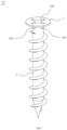
- FIG. 1 is a perspective view showing a bolt provided with openings according to an embodiment
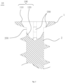
- FIG. 2 is a longitudinal sectional view showing the bolt provided with openings according to the embodiment
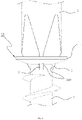
- FIG. 3 is a front view showing a state in which a tool is coupled to the bolt provided with openings according to the embodiment
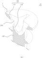
- FIG. 4 is a cut-away perspective view showing the main part of the bolt provided with openings according to the embodiment
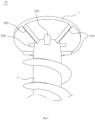
- FIG. 5 is a bottom perspective view showing a bolt provided with openings according to another embodiment.
- a bolt 10 provided with openings includes a head part 1 and a threaded part 2, as shown in FIGS. 1 and 2 .
- the bolt 10 provided with openings is a fastener that is fastened to a structure through the threaded part 2 while being rotated by a tool 3 such as a driver.
- the bolt 10 provided with openings may include a coupling recess 100 and openings 200.
- the coupling recess 100 is a portion that provides a coupling portion for the tool 3, and is formed in a recess shape corresponding to that of the tool 3 so that the tool 3 can be inserted and coupled thereinto.
- the coupling recess 100 may be formed in a "+" cross-sectional shape as shown in FIG. 1 and allow the coupling of a "+”-shaped driver.
- the coupling recess 100 may be formed in a "-" cross-sectional shape unlike the shape shown in the drawing and allow the coupling of a "-"-shaped driver.
- the coupling recess 100 may be formed in a cross-sectional shape corresponding to the cross-sectional shape of a polygonal wrench.
- the coupling recess 100 may be formed in a shape corresponding to the shape of the tool regardless of the type of tool.
- the coupling recess 100 may be formed in the head part 1, as shown in FIGS. 1 and 2 . Unlike in the method shown in the drawing, it may be formed in the threaded part 2 and allow the tool 3 to be coupled thereto.
- the bolt 10 provided with openings according to the present embodiment may be configured such that the coupling recess 100 extends to the head part 1 and the threaded part 2, as shown in FIG. 2 .
- the coupling recess 100 may include an entrance portion 110 and an accommodation portion 120, as shown in FIG. 2 .
- the entrance portion 110 is a portion forming the entrance of the coupling recess 100 configured to accommodate the tool 3, and may be formed in the head part 1.
- the entrance portion 110 may be formed to have a width corresponding to the width of the tool 3.
- the entrance portion 110 may be formed to have a width greater than that of the threaded part 2, as shown in FIG. 2 , but is not limited thereto.
- the accommodation portion 120 is a portion extending from the inlet portion 110 to the threaded part 2, and accommodates the tool 3 coupled through the entrance portion 110.
- the accommodation portion 120 may extend to the threaded part 2 through the head part 1 while extending from the entrance portion 110 toward the threaded part 2. Openings 200 to be described later are formed, so that portions of the tool 3 may be exposed to the outside.
- the accommodation portion 120 may extend while forming a width corresponding to the width of the tool 3.
- the accommodation portion 120 may be formed to extend to the threaded part 2 while forming the same width as the entrance portion 110.
- the accommodation portion 120 may be formed to extend while forming an inclination of a predetermined angle so that the width thereof is narrowed gradually in a direction from the entrance portion 110 to the threaded part 2.
- the accommodation portion 120 may extend while forming an inclination so that the width thereof is narrowed in the direction of the threaded part 2.
- the accommodation portion 120 may extend to reach a width less than the width of the threaded part 2 while extending to the threaded part 2.
- the openings 200 are portions that are formed in portions of the coupling recess 100 in the shape of holes, as shown in FIG. 2 , so that at least portions of the tool 3 coupled to the coupling recess 100 are exposed out of the head part 1 or the threaded part 2, as shown in FIG. 3 .
- the openings 200 may expose portions of the tool 3 by allowing portions of the coupling recess 100 to communicate with the outside, and the effect of discharging the foreign materials introduced into the coupling recess 100 or dissipating the heat applied to the head part 1 may be expected.
- the openings 200 may enable the head part 1 or the threaded part 2 to be fixed to the base material of a structure by allowing the introduction of an adhesive after the fastening of the threaded part 2 has been completed.
- the openings 200 may be formed in the accommodation portion 120 forming part of the coupling recess 100, and may be formed through the head part 1 or the threaded part 2.
- portions of the tool 3 accommodated in the accommodation portion 120 may be exposed to be seen through the openings 200, but the tool 3 may not be exposed while protruding out of the head part 1 or the threaded part 2.
- the openings 200 may be formed in the accommodation portion 120, and may be formed through the boundary portion between the head part 1 and the threaded part 2, as shown in FIGS. 2 and 4 .
- the openings 200 may connect the inclined surface of the accommodation portion 120 while being formed through the boundary portion between the head part 1 and the threaded part 2.
- the accommodation portion 120 may extend through the medium of the openings 200 while extending along an inclination of an angle passing through the boundary portion between the head part 1 and the threaded part 2.
- portions of the tool 3 may be exposed while protruding out of the head part 1 and the threaded part 2, as shown in FIG. 3 .
- the height of the head part 1 may be formed to be lower than that of a conventional bolt 5 and also the depth of the coupling recess 100 may be formed to be relatively deep, as shown in FIG. 6 .
- the openings 200 may be applied regardless of the shape of the head 1, such as the shape of a flat head bolt shown in FIG. 6 (a) or the shape of a round head bolt shown in FIG. 6(b) , and thus the height of the head part 1 may be allowed to be relatively low.
- the tool 3 is exposed to the outside through the openings 200, so that when the threaded part 2 is fastened to a structure, the completion of the fastening of the threaded part 2 may be detected as the tool 3 comes into direct contact with the surface of the structure.
- the openings 200 may be formed through the boundary portion between the head part 1 and the threaded part 2.
- the openings 200 may expose portions of the tool 3 to be seed through the openings 200 while being formed through the boundary portion between the head part 1 and the threaded part2, they may not expose portions of the tool 3 while allowing the portions of the tool 3 to protrude out of the head part 1 or the threaded part 2.
- a bolt 10 provided with openings may further include one or more anti-loosening protrusions 500, as shown in FIG. 5 .
- the anti-loosening protrusions 500 are portions that prevent the loosening of the fastened threaded part 2.
- the anti-loosening protrusions 500 may protrude from the bottom surface of the head part 1 while forming a plurality of anti-loosening protrusions, and may come into close contact with and be caught on the base material of a structure by the fastening of the threaded part 2, thereby preventing the head part 1 from being rotated arbitrarily.
- the anti-loosening protrusions 500 may protrude from the bottom of the head part 1 while forming wedge-shaped cross sections, and may protrude in a direction opposite to the direction in which the threaded part 2 is tightened.
- the anti-loosening protrusions 500 protrude in the direction opposite to the direction in which the threaded part 2 is tightened and are caught on the base material of the structure. Accordingly, even when repeated vibration or shock is applied to the head part 1, the anti-loosening protrusions 500 may prevent the threaded part 2 from being loosened by restraining the rotation of the head part 1.
- the anti-loosening protrusions 500 may protrude in a direction corresponding to the direction in which the threaded part 2 is tightened while forming wedge-shaped cross sections.
- the anti-loosening protrusions 500 protrude in a forward direction corresponding to the direction in which the threaded part 2 is tightened, and face the surface of a structure when the threaded part 2 is fastened, thereby stopping the rotation of the threaded part 2.
- the threaded part 2 may be fastened to a structure while being rotated by the tool 3 coupled to the coupling recess 100 of the head part 1.
- the tool 3 may rotate the head part 1 and the threaded part 2 while partially protruding through the openings 200.
- the completion of the fastening of the threaded part 2 may be detected based on a direct contact with the surface of the structure.
- the head part 1 is formed to have a relatively low height by the openings 200, the volume of an installation portion may be reduced.
- the head part 1 may be prevented from being undesirably loosened by being fixed to the surface of a structure in the state of being caught on the surface of the structure through the anti-loosening protrusions 500 protruding from the bottom surface of the head part 1.
- the head part 1 may be fixed in the state of being fastened to a structure by introducing an adhesive through the openings 200 after the fastening to the structure has been completed.
- the accommodation portion 120 constituting part of the coupling recess 100 extends at an angle passing through the boundary portion between the head part 1 and the threaded part 2, and the openings 200 are formed through the boundary portion between the head part 1 and the threaded part 2. Accordingly, the height of the head part 1 is formed to be relatively low, so that material may be reduced during the manufacture of the bolt and the volume and weight of the bolt may be also reduced.
Landscapes
- Engineering & Computer Science (AREA)
- General Engineering & Computer Science (AREA)
- Mechanical Engineering (AREA)
- Connection Of Plates (AREA)
- Dowels (AREA)
- Mutual Connection Of Rods And Tubes (AREA)
- Furniture Connections (AREA)
Applications Claiming Priority (2)
| Application Number | Priority Date | Filing Date | Title |
|---|---|---|---|
| KR1020200055616A KR102246328B1 (ko) | 2020-05-11 | 2020-05-11 | 개구부가 구비된 볼트 |
| PCT/KR2020/008506 WO2021230420A1 (ko) | 2020-05-11 | 2020-06-30 | 개구부가 구비된 볼트 |
Publications (4)
| Publication Number | Publication Date |
|---|---|
| EP4151868A1 true EP4151868A1 (de) | 2023-03-22 |
| EP4151868A4 EP4151868A4 (de) | 2024-06-05 |
| EP4151868B1 EP4151868B1 (de) | 2025-12-24 |
| EP4151868C0 EP4151868C0 (de) | 2025-12-24 |
Family
ID=75728411
Family Applications (1)
| Application Number | Title | Priority Date | Filing Date |
|---|---|---|---|
| EP20935101.4A Active EP4151868B1 (de) | 2020-05-11 | 2020-06-30 | Bolzen mit öffnung |
Country Status (9)
| Country | Link |
|---|---|
| US (1) | US20210348639A1 (de) |
| EP (1) | EP4151868B1 (de) |
| JP (1) | JP7655570B2 (de) |
| KR (1) | KR102246328B1 (de) |
| CN (1) | CN113994109B (de) |
| AU (1) | AU2020448169B2 (de) |
| BR (1) | BR112022017054A2 (de) |
| PH (1) | PH12022552017A1 (de) |
| WO (1) | WO2021230420A1 (de) |
Family Cites Families (53)
| Publication number | Priority date | Publication date | Assignee | Title |
|---|---|---|---|---|
| US296982A (en) * | 1884-04-15 | Jesse b | ||
| US52631A (en) * | 1866-02-13 | Improvement in screws and bolts | ||
| US1175665A (en) * | 1915-09-29 | 1916-03-14 | William Russell Sweet | Wood-screw. |
| US1365508A (en) * | 1920-04-21 | 1921-01-11 | Kucewicz John | Screw |
| GB346893A (en) * | 1930-02-05 | 1931-04-23 | John Lidbetter | Improvements in and connected with screws |
| US2046343A (en) * | 1934-07-03 | 1936-07-07 | Phillips Screw Co | Screw |
| US2445525A (en) * | 1945-02-19 | 1948-07-20 | Moses L Gulden | Fastening device |
| US2550357A (en) * | 1945-03-30 | 1951-04-24 | Lockheed Aircraft Corp | Sealable fastening device |
| US3288190A (en) * | 1964-09-21 | 1966-11-29 | John F Holmes | Self-locking screw with friction reducing driving means |
| GB1496360A (en) * | 1974-12-23 | 1977-12-30 | Militana F | Self-locking threaded fasteners |
| US4033244A (en) * | 1976-04-27 | 1977-07-05 | Ralph Spencer Jacobson | Screw and screw driver |
| US4445264A (en) * | 1982-03-09 | 1984-05-01 | Carl Banerian | Tool for a method of forming dimples in sheet metal for recessing rivet heads |
| FR2566068A1 (fr) * | 1984-06-18 | 1985-12-20 | Garcin F | Vis perfectionnee et tournevis permettant de l'actionner |
| US4669597A (en) * | 1985-11-04 | 1987-06-02 | Otis Elevator Company | Escalator skirt panel |
| GB2244775B (en) * | 1990-06-05 | 1993-08-11 | Titus Tool Co Ltd | Screws |
| DE4036267A1 (de) * | 1990-11-14 | 1992-05-21 | Reelitz Sigrid | Knopflochschraube mit schraubenzieher |
| JPH0571522A (ja) * | 1991-05-29 | 1993-03-23 | Toopura:Kk | ドリリングねじ |
| US5275601A (en) * | 1991-09-03 | 1994-01-04 | Synthes (U.S.A) | Self-locking resorbable screws and plates for internal fixation of bone fractures and tendon-to-bone attachment |
| US5249899A (en) * | 1992-10-28 | 1993-10-05 | Wilson Robert L | Head bolt and driver therefore |
| JPH08299362A (ja) * | 1995-05-08 | 1996-11-19 | Terumo Corp | 骨ネジ組立体 |
| DE19636653C2 (de) * | 1996-09-10 | 2002-09-26 | Lux Elements Gmbh & Co Kg | Schraubenartiges Verbindendungselement sowie Verfahren zum Verbinden von Hartschaumplatten miteinander |
| KR19990009107A (ko) | 1997-07-07 | 1999-02-05 | 윤종용 | 테스트 패드 병합수단을 구비하는 복합 반도체장치 |
| KR200183422Y1 (ko) * | 1999-12-15 | 2000-05-15 | 박해균 | 스크류의 머리 |
| US6440136B1 (en) * | 2000-05-24 | 2002-08-27 | Medtronic Ps Medical, Inc. | Apparatus for attaching to bone |
| US6334748B1 (en) * | 2000-12-11 | 2002-01-01 | Sigurdur Gudjonsson | Screw with cutting head and self tapping cutter |
| US20020098061A1 (en) * | 2001-01-24 | 2002-07-25 | Fastenair, Inc. | Tapered fastener for deforming parent materal aperture whereby the aperture conforms to fastener taper |
| JP2003010200A (ja) * | 2001-06-29 | 2003-01-14 | Sayama Precision Ind Co | 骨接合用中空スクリュー及び着脱工具 |
| JP2003021123A (ja) * | 2001-07-09 | 2003-01-24 | Wood One:Kk | ね じ |
| US6620167B2 (en) * | 2001-10-17 | 2003-09-16 | Ricahrd J. Deslauriers | Orthopedic screw having driver-locking head |
| US20050096657A1 (en) * | 2002-02-26 | 2005-05-05 | Alex Autericque | Osteosynthesis or arthrodesis material comprising a bony plate |
| WO2003072962A1 (en) * | 2002-02-26 | 2003-09-04 | Degima Medizinprodukte Gmbh | Threaded device with improved resistance against torsion-caused breakage |
| AU2002950242A0 (en) * | 2002-07-18 | 2002-09-12 | Itw Afc Pty Ltd | Screws |
| AU2003206600B2 (en) * | 2003-03-07 | 2007-08-23 | Synthes Gmbh | Locking screw for an intramedullary nail |
| CN2615411Y (zh) * | 2003-04-25 | 2004-05-12 | 张云昌 | 速进木螺钉及其专用工具 |
| US7909860B2 (en) * | 2003-09-03 | 2011-03-22 | Synthes Usa, Llc | Bone plate with captive clips |
| WO2005047716A1 (ja) * | 2003-11-14 | 2005-05-26 | Katsuyuki Totsu | 強度安定型ねじ及びドライバービットとの組合せ並びに強度安定型ねじ製造用ヘッダーパンチ |
| JP2006046624A (ja) * | 2004-08-01 | 2006-02-16 | Yasuo Ishiguro | ネジとドライバー |
| CN2740830Y (zh) * | 2004-08-31 | 2005-11-16 | 张平 | 倒t形槽螺栓头及配套使用的螺丝刀 |
| TWM296931U (en) * | 2006-03-24 | 2006-09-01 | Chiou-Yue Wang | Screw |
| JP2010052089A (ja) * | 2008-08-28 | 2010-03-11 | Katsuyuki Totsu | ドライバービット及びねじ並びにこれらの組合せ |
| US8496692B2 (en) * | 2009-09-21 | 2013-07-30 | Jmea Corporation | Locking securing member |
| AU2009230753C1 (en) * | 2009-09-30 | 2015-11-26 | Craig Stanley Harvey | Self-countersinking fastener |
| CN201836192U (zh) * | 2010-08-11 | 2011-05-18 | 新邮通信设备有限公司 | 一种螺钉以及开启该螺钉的工具 |
| CN102116336B (zh) * | 2010-12-30 | 2013-01-23 | 曹蕾 | 连接件 |
| US20120312130A1 (en) * | 2011-06-08 | 2012-12-13 | Jason Bauer | Fasteners and fastening systems |
| KR20130055463A (ko) * | 2011-11-18 | 2013-05-28 | 장정훈 | 접착형 나사체결구 |
| GB2498769A (en) * | 2012-01-27 | 2013-07-31 | Hardie James Technology Ltd | Fastener with cap |
| US8911189B2 (en) * | 2013-02-26 | 2014-12-16 | Apical Industries, Inc. | Frangible fastener |
| CN203297265U (zh) * | 2013-04-27 | 2013-11-20 | 宁波永宏紧固件制造有限公司 | 一种椭圆螺栓 |
| JP6518494B2 (ja) * | 2015-04-10 | 2019-05-22 | イワタボルト株式会社 | 固着ボルト及びその固着方法 |
| CN205780162U (zh) * | 2016-06-01 | 2016-12-07 | 广州市中标螺丝制造有限公司 | 一种沉头快速牙螺钉 |
| CN208974164U (zh) * | 2018-05-14 | 2019-06-14 | 广州市德伦口腔门诊部有限公司 | 一种牙科即刻种植仿生牙基体结构 |
| CN108488180B (zh) * | 2018-05-21 | 2024-03-12 | 中国电建集团中南勘测设计研究院有限公司 | 一种对中底盘的保护螺栓及开启装置、保护结构 |
-
2020
- 2020-05-11 KR KR1020200055616A patent/KR102246328B1/ko active Active
- 2020-06-30 JP JP2022545035A patent/JP7655570B2/ja active Active
- 2020-06-30 PH PH1/2022/552017A patent/PH12022552017A1/en unknown
- 2020-06-30 WO PCT/KR2020/008506 patent/WO2021230420A1/ko not_active Ceased
- 2020-06-30 EP EP20935101.4A patent/EP4151868B1/de active Active
- 2020-06-30 BR BR112022017054A patent/BR112022017054A2/pt active Search and Examination
- 2020-06-30 CN CN202080041698.5A patent/CN113994109B/zh active Active
- 2020-06-30 AU AU2020448169A patent/AU2020448169B2/en active Active
-
2021
- 2021-05-07 US US17/314,208 patent/US20210348639A1/en active Pending
Also Published As
| Publication number | Publication date |
|---|---|
| EP4151868B1 (de) | 2025-12-24 |
| JP7655570B2 (ja) | 2025-04-02 |
| AU2020448169B2 (en) | 2024-09-19 |
| CN113994109B (zh) | 2023-05-23 |
| EP4151868A4 (de) | 2024-06-05 |
| JP2023519649A (ja) | 2023-05-12 |
| PH12022552017A1 (en) | 2023-11-29 |
| AU2020448169A1 (en) | 2022-08-18 |
| CN113994109A (zh) | 2022-01-28 |
| US20210348639A1 (en) | 2021-11-11 |
| WO2021230420A1 (ko) | 2021-11-18 |
| BR112022017054A2 (pt) | 2022-12-06 |
| KR102246328B1 (ko) | 2021-04-29 |
| EP4151868C0 (de) | 2025-12-24 |
| CA3167486A1 (en) | 2021-11-18 |
Similar Documents
| Publication | Publication Date | Title |
|---|---|---|
| US9732783B2 (en) | Anti-loosening bolt assembly | |
| US6676352B2 (en) | Fasteners with improved retaining effect | |
| CA2048689C (en) | Self-drilling fastening | |
| US20100226711A1 (en) | Joining device for two bar-type hollow profiled members, and method for the production thereof | |
| MX2010007702A (es) | Dispositivo de conexion y metodo para crear una conexion para tornillo. | |
| EP4151868A1 (de) | Bolzen mit öffnung | |
| CA3167486C (en) | Bolt provided with openings | |
| US20230080323A1 (en) | Fastener, fastening structure, and method of designing fastener | |
| JP6779568B2 (ja) | 締付トルク管理具、締付トルク管理具付ナット及びボルト、並びに取付物の取付方法 | |
| JP6846986B2 (ja) | 締付トルク管理具及び締付トルク管理具と締結具との組み合わせ | |
| US5201624A (en) | One-piece fastener anchor | |
| US20110170986A1 (en) | Threaded Stud With Locking Pawl | |
| JP4294802B2 (ja) | 薄板締結用の座金付きドリルねじ | |
| KR20210155585A (ko) | 개구부 및 나사부마커가 구비된 볼트 | |
| US20070212191A1 (en) | Two piece weld nut | |
| AU2005333514B8 (en) | Pin fastener for achieving metal-to-metal connections | |
| KR102935994B1 (ko) | 풀림 방지형 나사 | |
| JP7495217B2 (ja) | 締付トルク管理具及び締付トルク管理具と締結具との組み合わせ | |
| KR102324647B1 (ko) | 렌치 탭핑 스크류 볼트 | |
| JP7495218B2 (ja) | 締付トルク管理具及び締付トルク管理具と締結具との組み合わせ | |
| US12104637B1 (en) | Locking fastener utilizing an inserted key | |
| JP3104596U (ja) | ロックナット | |
| KR20200000463U (ko) | 락 기능을 갖는 볼트 너트 체결부재 | |
| JP7658720B2 (ja) | トルク管理具 | |
| KR20250055880A (ko) | 헤드 고정부가 구비된 볼트 |
Legal Events
| Date | Code | Title | Description |
|---|---|---|---|
| STAA | Information on the status of an ep patent application or granted ep patent |
Free format text: STATUS: THE INTERNATIONAL PUBLICATION HAS BEEN MADE |
|
| PUAI | Public reference made under article 153(3) epc to a published international application that has entered the european phase |
Free format text: ORIGINAL CODE: 0009012 |
|
| STAA | Information on the status of an ep patent application or granted ep patent |
Free format text: STATUS: REQUEST FOR EXAMINATION WAS MADE |
|
| 17P | Request for examination filed |
Effective date: 20220812 |
|
| AK | Designated contracting states |
Kind code of ref document: A1 Designated state(s): AL AT BE BG CH CY CZ DE DK EE ES FI FR GB GR HR HU IE IS IT LI LT LU LV MC MK MT NL NO PL PT RO RS SE SI SK SM TR |
|
| DAV | Request for validation of the european patent (deleted) | ||
| DAX | Request for extension of the european patent (deleted) | ||
| A4 | Supplementary search report drawn up and despatched |
Effective date: 20240503 |
|
| RIC1 | Information provided on ipc code assigned before grant |
Ipc: F16B 39/282 20060101ALI20240427BHEP Ipc: F16B 23/00 20060101ALI20240427BHEP Ipc: F16B 35/06 20060101AFI20240427BHEP |
|
| GRAP | Despatch of communication of intention to grant a patent |
Free format text: ORIGINAL CODE: EPIDOSNIGR1 |
|
| STAA | Information on the status of an ep patent application or granted ep patent |
Free format text: STATUS: GRANT OF PATENT IS INTENDED |
|
| INTG | Intention to grant announced |
Effective date: 20250721 |
|
| GRAS | Grant fee paid |
Free format text: ORIGINAL CODE: EPIDOSNIGR3 |
|
| GRAA | (expected) grant |
Free format text: ORIGINAL CODE: 0009210 |
|
| STAA | Information on the status of an ep patent application or granted ep patent |
Free format text: STATUS: THE PATENT HAS BEEN GRANTED |
|
| AK | Designated contracting states |
Kind code of ref document: B1 Designated state(s): AL AT BE BG CH CY CZ DE DK EE ES FI FR GB GR HR HU IE IS IT LI LT LU LV MC MK MT NL NO PL PT RO RS SE SI SK SM TR |
|
| REG | Reference to a national code |
Ref country code: CH Ref legal event code: F10 Free format text: ST27 STATUS EVENT CODE: U-0-0-F10-F00 (AS PROVIDED BY THE NATIONAL OFFICE) Effective date: 20251224 Ref country code: GB Ref legal event code: FG4D |
|
| REG | Reference to a national code |
Ref country code: DE Ref legal event code: R096 Ref document number: 602020064583 Country of ref document: DE |
|
| U01 | Request for unitary effect filed |
Effective date: 20260123 |
|
| U07 | Unitary effect registered |
Designated state(s): AT BE BG DE DK EE FI FR IT LT LU LV MT NL PT RO SE SI Effective date: 20260129 |
|
| PG25 | Lapsed in a contracting state [announced via postgrant information from national office to epo] |
Ref country code: NO Free format text: LAPSE BECAUSE OF FAILURE TO SUBMIT A TRANSLATION OF THE DESCRIPTION OR TO PAY THE FEE WITHIN THE PRESCRIBED TIME-LIMIT Effective date: 20260324 |
|
| PG25 | Lapsed in a contracting state [announced via postgrant information from national office to epo] |
Ref country code: HR Free format text: LAPSE BECAUSE OF FAILURE TO SUBMIT A TRANSLATION OF THE DESCRIPTION OR TO PAY THE FEE WITHIN THE PRESCRIBED TIME-LIMIT Effective date: 20251224 |
|
| PG25 | Lapsed in a contracting state [announced via postgrant information from national office to epo] |
Ref country code: RS Free format text: LAPSE BECAUSE OF FAILURE TO SUBMIT A TRANSLATION OF THE DESCRIPTION OR TO PAY THE FEE WITHIN THE PRESCRIBED TIME-LIMIT Effective date: 20260324 |