EP4132006A1 - Émetteur-récepteur à ultrasons, débitmètre à ultrasons, vélocimètre à ultrasons, densitomètre à ultrasons et procédé de fabrication - Google Patents
Émetteur-récepteur à ultrasons, débitmètre à ultrasons, vélocimètre à ultrasons, densitomètre à ultrasons et procédé de fabrication Download PDFInfo
- Publication number
- EP4132006A1 EP4132006A1 EP21778959.3A EP21778959A EP4132006A1 EP 4132006 A1 EP4132006 A1 EP 4132006A1 EP 21778959 A EP21778959 A EP 21778959A EP 4132006 A1 EP4132006 A1 EP 4132006A1
- Authority
- EP
- European Patent Office
- Prior art keywords
- ultrasonic
- acoustic matching
- matching body
- bottom plate
- closed
- Prior art date
- Legal status (The legal status is an assumption and is not a legal conclusion. Google has not performed a legal analysis and makes no representation as to the accuracy of the status listed.)
- Pending
Links
Images


Classifications
-
- G—PHYSICS
- G01—MEASURING; TESTING
- G01N—INVESTIGATING OR ANALYSING MATERIALS BY DETERMINING THEIR CHEMICAL OR PHYSICAL PROPERTIES
- G01N29/00—Investigating or analysing materials by the use of ultrasonic, sonic or infrasonic waves; Visualisation of the interior of objects by transmitting ultrasonic or sonic waves through the object
- G01N29/02—Analysing fluids
- G01N29/024—Analysing fluids by measuring propagation velocity or propagation time of acoustic waves
-
- G—PHYSICS
- G01—MEASURING; TESTING
- G01F—MEASURING VOLUME, VOLUME FLOW, MASS FLOW OR LIQUID LEVEL; METERING BY VOLUME
- G01F1/00—Measuring the volume flow or mass flow of fluid or fluent solid material wherein the fluid passes through a meter in a continuous flow
- G01F1/66—Measuring the volume flow or mass flow of fluid or fluent solid material wherein the fluid passes through a meter in a continuous flow by measuring frequency, phase shift or propagation time of electromagnetic or other waves, e.g. using ultrasonic flowmeters
- G01F1/667—Arrangements of transducers for ultrasonic flowmeters; Circuits for operating ultrasonic flowmeters
-
- B—PERFORMING OPERATIONS; TRANSPORTING
- B06—GENERATING OR TRANSMITTING MECHANICAL VIBRATIONS IN GENERAL
- B06B—METHODS OR APPARATUS FOR GENERATING OR TRANSMITTING MECHANICAL VIBRATIONS OF INFRASONIC, SONIC, OR ULTRASONIC FREQUENCY, e.g. FOR PERFORMING MECHANICAL WORK IN GENERAL
- B06B1/00—Methods or apparatus for generating mechanical vibrations of infrasonic, sonic, or ultrasonic frequency
- B06B1/02—Methods or apparatus for generating mechanical vibrations of infrasonic, sonic, or ultrasonic frequency making use of electrical energy
- B06B1/06—Methods or apparatus for generating mechanical vibrations of infrasonic, sonic, or ultrasonic frequency making use of electrical energy operating with piezoelectric effect or with electrostriction
- B06B1/0644—Methods or apparatus for generating mechanical vibrations of infrasonic, sonic, or ultrasonic frequency making use of electrical energy operating with piezoelectric effect or with electrostriction using a single piezoelectric element
- B06B1/0662—Methods or apparatus for generating mechanical vibrations of infrasonic, sonic, or ultrasonic frequency making use of electrical energy operating with piezoelectric effect or with electrostriction using a single piezoelectric element with an electrode on the sensitive surface
- B06B1/067—Methods or apparatus for generating mechanical vibrations of infrasonic, sonic, or ultrasonic frequency making use of electrical energy operating with piezoelectric effect or with electrostriction using a single piezoelectric element with an electrode on the sensitive surface which is used as, or combined with, an impedance matching layer
-
- G—PHYSICS
- G01—MEASURING; TESTING
- G01F—MEASURING VOLUME, VOLUME FLOW, MASS FLOW OR LIQUID LEVEL; METERING BY VOLUME
- G01F1/00—Measuring the volume flow or mass flow of fluid or fluent solid material wherein the fluid passes through a meter in a continuous flow
- G01F1/66—Measuring the volume flow or mass flow of fluid or fluent solid material wherein the fluid passes through a meter in a continuous flow by measuring frequency, phase shift or propagation time of electromagnetic or other waves, e.g. using ultrasonic flowmeters
- G01F1/662—Constructional details
-
- G—PHYSICS
- G01—MEASURING; TESTING
- G01F—MEASURING VOLUME, VOLUME FLOW, MASS FLOW OR LIQUID LEVEL; METERING BY VOLUME
- G01F1/00—Measuring the volume flow or mass flow of fluid or fluent solid material wherein the fluid passes through a meter in a continuous flow
- G01F1/704—Measuring the volume flow or mass flow of fluid or fluent solid material wherein the fluid passes through a meter in a continuous flow using marked regions or existing inhomogeneities within the fluid stream, e.g. statistically occurring variations in a fluid parameter
- G01F1/708—Measuring the time taken to traverse a fixed distance
- G01F1/7082—Measuring the time taken to traverse a fixed distance using acoustic detecting arrangements
-
- G—PHYSICS
- G01—MEASURING; TESTING
- G01N—INVESTIGATING OR ANALYSING MATERIALS BY DETERMINING THEIR CHEMICAL OR PHYSICAL PROPERTIES
- G01N29/00—Investigating or analysing materials by the use of ultrasonic, sonic or infrasonic waves; Visualisation of the interior of objects by transmitting ultrasonic or sonic waves through the object
- G01N29/22—Details, e.g. general constructional or apparatus details
- G01N29/222—Constructional or flow details for analysing fluids
-
- G—PHYSICS
- G01—MEASURING; TESTING
- G01N—INVESTIGATING OR ANALYSING MATERIALS BY DETERMINING THEIR CHEMICAL OR PHYSICAL PROPERTIES
- G01N29/00—Investigating or analysing materials by the use of ultrasonic, sonic or infrasonic waves; Visualisation of the interior of objects by transmitting ultrasonic or sonic waves through the object
- G01N29/22—Details, e.g. general constructional or apparatus details
- G01N29/28—Details, e.g. general constructional or apparatus details providing acoustic coupling, e.g. water
-
- G—PHYSICS
- G10—MUSICAL INSTRUMENTS; ACOUSTICS
- G10K—SOUND-PRODUCING DEVICES; METHODS OR DEVICES FOR PROTECTING AGAINST, OR FOR DAMPING, NOISE OR OTHER ACOUSTIC WAVES IN GENERAL; ACOUSTICS NOT OTHERWISE PROVIDED FOR
- G10K11/00—Methods or devices for transmitting, conducting or directing sound in general; Methods or devices for protecting against, or for damping, noise or other acoustic waves in general
- G10K11/02—Mechanical acoustic impedances; Impedance matching, e.g. by horns; Acoustic resonators
-
- G—PHYSICS
- G01—MEASURING; TESTING
- G01N—INVESTIGATING OR ANALYSING MATERIALS BY DETERMINING THEIR CHEMICAL OR PHYSICAL PROPERTIES
- G01N2291/00—Indexing codes associated with group G01N29/00
- G01N2291/02—Indexing codes associated with the analysed material
- G01N2291/028—Material parameters
- G01N2291/02809—Concentration of a compound, e.g. measured by a surface mass change
-
- G—PHYSICS
- G01—MEASURING; TESTING
- G01N—INVESTIGATING OR ANALYSING MATERIALS BY DETERMINING THEIR CHEMICAL OR PHYSICAL PROPERTIES
- G01N2291/00—Indexing codes associated with group G01N29/00
- G01N2291/02—Indexing codes associated with the analysed material
- G01N2291/028—Material parameters
- G01N2291/02836—Flow rate, liquid level
-
- G—PHYSICS
- G01—MEASURING; TESTING
- G01N—INVESTIGATING OR ANALYSING MATERIALS BY DETERMINING THEIR CHEMICAL OR PHYSICAL PROPERTIES
- G01N2291/00—Indexing codes associated with group G01N29/00
- G01N2291/10—Number of transducers
- G01N2291/105—Number of transducers two or more emitters, two or more receivers
Definitions
- the present disclosure relates to an ultrasonic transceiver and measuring instruments configured to measure the flow rate, flow velocity, and concentration of a fluid, respectively, by using the ultrasonic transceiver.
- Patent Literature 1 discloses ultrasonic transceiver 51 including an acoustic matching body having high sensitivity to transmit and receive ultrasonic waves, high mechanical strength, and high heat-resistance.
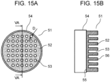
- FIG. 15A is a plan view of conventional ultrasonic transceiver 51.
- FIG. 15B is a cross-sectional view of ultrasonic transceiver 51 taken along line VA-VA illustrated in FIG. 15A .
- ultrasonic transceiver 51 includes a sound matching layer.
- the sound matching layer includes a plate-like base member having a predetermined thickness, dense portion 52, and recessed portion 53.
- the base member includes: joint face 55 formed on one side of the base member and joined to ultrasonic wave source 54; and oscillating face 56 formed on the other side of the base member and configured to emit an ultrasonic wave. Dense portion 52 and recessed portion 53 are partly provided in at least oscillating face 56 toward joint face 55.
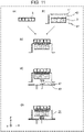
- FIG. 16 is a diagram illustrating a conventional ultrasonic transceiver.
- Patent Literature 2 discloses an ultrasonic transceiver in which edge portion 62 of one main face 61 of sound matching layer 60 is fixed to the upper end face of tubular case 63, the other main face 64 of sound matching layer 60 is covered with first water-proof member 65, side face 66 of sound matching layer 60 is covered with second water-proof member 67, second water-proof member 67 is joined to first water-proof member 65 without a gap in the vicinity of edge portion 68 of the other main face 64 of sound matching layer 60 and is also joined to case 63 without a gap in side face 69 of case 63.
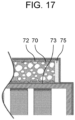
- FIG. 17 is a diagram illustrating a conventional ultrasonic transceiver.
- Patent Literature 3 discloses an ultrasonic transceiver including: a matching member including dense layer 72 laminated on a face of porous body 70 and formed of a thermosetting resin and flow-preventing particles; and side wall member 75 adhering to ultrasonic radiation face 73 and the outer wall face of porous body 70, wherein porous body 74 is sealed by dense layer 72 and side wall member 75, and the radial thickness of side wall member 75 is approximately uniform in the direction of ultrasonic radiation.
- the present disclosure provides an ultrasonic transceiver capable of stably measuring a measurement target fluid with high accuracy for a long period even when the measurement target fluid is a fluid of high temperature and high humidity, and provides an ultrasonic flowmeter, an ultrasonic flow velocimeter, and an ultrasonic densitometer, each including the ultrasonic transceiver.
- the ultrasonic transceiver is an ultrasonic transceiver including a piezoelectric body and an acoustic matching body disposed in one face of the piezoelectric body.
- the acoustic matching body includes: a top plate, a bottom plate, and a side wall that define a closed space; and a perpendicular partition wall adhering to the top plate and the bottom plate and formed substantially perpendicularly to the bottom plate so as to divide the closed space.
- the ultrasonic transceiver includes a piezoelectric body and an acoustic matching body disposed in one face of the piezoelectric body.
- the acoustic matching body includes a top plate, a bottom plate, and a side wall that define a closed space, and is formed so that the closed space is divided. Accordingly, even when corrosion deterioration occurs in the outer circumference of the acoustic matching body and a fluid of high humidity enters the acoustic matching body from a gap formed due to the corrosion deterioration, the spread of moisture entry in the whole of the acoustic matching body can be substantially prevented because of a plurality of the partitions.
- an ultrasonic flowmeter including the ultrasonic transceiver is capable of stably measuring the flow rate of a fluid of high temperature and high humidity with high accuracy for a long period.
- an ultrasonic flow velocimeter including the ultrasonic transceiver is capable of stably measuring the velocity of a fluid of high temperature and high humidity with high accuracy for a long period.
- an ultrasonic densitometer including the ultrasonic transceiver is capable of stably measuring the concentration of a fluid of high temperature and high humidity with high accuracy for a long period.
- the product of density and acoustic velocity indicates the momentum of a substance constituting a microscopic unit element of the certain substance.
- the momentum of the substance constituting the microscopic unit element be ⁇ P
- the mass of the substance be ⁇ M
- the speed of the substance be V
- the following formula (1) is derived based on the theorem of momentum.
- ⁇ P momentum ⁇ M ⁇ V acoustic impendance
- the formula (1) indicates that an acoustic impedance is the momentum of a substance constituting a microscopic unit element.
- the acoustic impedances of these two substances are desirably close to each other.
- the acoustic velocity of a substance is expressed by the following formula (2).
- V ⁇ / ⁇ 1 / 2
- ⁇ represents a bulk modulus
- ⁇ represents a density.
- the acoustic velocity of the substance is uniquely determined by a bulk modulus and a density. This indicates that intentionally controlling the acoustic velocity is difficult.
- An acoustic matching body includes a top plate, a bottom plate, and a side wall that define a closed space, and includes perpendicular partition walls formed substantially perpendicularly to the top plate and the bottom plate inside the closed space.
- the perpendicular partition walls are formed to adhere to the top plate and the bottom plate, thereby dividing the closed space.
- the inventors found the above-mentioned problem in the prior art, and to solve the problem, the inventors accomplished configurations for the subject matters of the present disclosure.
- the present disclosure provides an ultrasonic flowmeter, an ultrasonic flow velocimeter, and an ultrasonic densitometer, each being capable of stably measuring a measurement target fluid with high accuracy for a long period even when the measurement target fluid is a fluid of high temperature and high humidity.
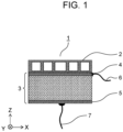
- FIG. 1 is a schematic cross-sectional view of a configuration example of ultrasonic transceiver 1 in the first embodiment.
- FIG. 1 is a cross-sectional view (a cross-sectional view in the X-Z plane) taken along the thickness direction (parallel to the Z-axis) of ultrasonic transceiver 1.
- ultrasonic transceiver 1 includes acoustic matching body 2, piezoelectric body 3, lead wire 6 connected to electrode 4 of piezoelectric body 3, and lead wire 7 connected to electrode 5 of piezoelectric body 3.
- Electrode 4 of piezoelectric body 3 and acoustic matching body 2 are joined using a joining material.
- a joining material such as an epoxy adhesive, a phenol adhesive, or a cyanoacrylate adhesive
- electrode 4 and acoustic matching body 2 can be joined.
- FIG. 2 is a cross-sectional view of a configuration example of acoustic matching body 2 according to the first embodiment.
- (a) of FIG. 2 is a cross-sectional view (a cross-sectional view in the X-Z plane) taken along the thickness direction (parallel to the Z-axis) of acoustic matching body 2.
- (b) of FIG. 2 is a cross-sectional view taken along line II-II illustrated in (a) of FIG. 2 , specifically, a cross-sectional view (a cross-sectional view in the X-Y plane) taken along a direction (parallel to the X-Y plane) perpendicular to the thickness direction of acoustic matching body 2.
- acoustic matching body 2 includes top plate 8, bottom plate 9, side wall 10, and perpendicular partition walls 12.
- top plate 8 and bottom plate 9 are joined to side wall 10 to define closed space 11, and perpendicular partition walls 12 are formed to divide closed space 11 into a plurality of closed spaces.
- Perpendicular partition walls 12 are disposed substantially perpendicularly to top plate 8 and bottom plate 9 (extend in substantially parallel to the Z-axis), and are integrally joined to top plate 8 and bottom plate 9.
- closed space 11 is partitioned into the closed spaces by perpendicular partition walls 12.
- acoustic matching body 2 includes two perpendicular partition walls 12 disposed concentrically and eight perpendicular partition walls 12 disposed to linearly extend in the radial direction, when the acoustic matching body 2 according to the first embodiment is viewed from above (in parallel to the Z-axis).
- closed space 11 is divided into one circular closed space and 16 sector-shaped closed spaces.
- the shape and number of perpendicular partition walls 12 disposed in closed space 11 are not limited to the shape and number illustrated in FIG. 2 . Other examples of the shape of the perpendicular partition walls will be described later.
- FIG. 3 is a diagram illustrating a procedure for manufacturing acoustic matching body 2 in the first embodiment by using perspective views. The steps for manufacturing acoustic matching body 2 are performed in the order of (a), (b), (c), and (d) illustrated in FIG. 3 .
- metal plate 13 is circularly patterned to produce a plurality of metal plates 14a serving as top plate 8 and bottom plate 9, and a plurality of metal plates 14b patterned with side wall 10 and perpendicular partition walls 12 of acoustic matching body 2 is produced from metal plate 13.
- punching of metal plate 13 with a press etching by photolithography, laser processing, or processing using an electric discharge wire can be applied.
- metal plates 14a and 14b are formed to have a circular (disc-like) external shape when viewed from above (viewed in parallel to the Z-axis).
- this is merely an example, and the external shape of metal plates 14a and 14b according to the present disclosure is not limited to a circular shape (a disc-shape), and may be an elliptical shape or a polygonal shape.
- metal plates 14a and metal plates 14b are positioned and laminated. Specifically, first, a predetermined number of metal plates 14b are laminated. Next, metal plate 14a serving as top plate 8 is laminated on the top face of laminated metal plates 14b (a face on the Z-axis positive direction side of metal plate 14b disposed at an end in the Z-axis positive direction). Next, metal plate 14a serving as bottom plate 9 is laminated on the bottom face of laminated metal plates 14b (a face on the Z-axis negative direction side of metal plate 14b disposed at an end in the Z-axis negative direction). The patterned metal plates are joined by heating and pressurization to become an integrated member by diffusion joining.
- temperature in the diffusion joining is approximately 1000°C, and therefore, in the case where laminated metal plates 14a and 14b are made of stainless steel, laminated metal plates 14a and 14b are heated to the above-mentioned temperature and pressurized to perform diffusion joining.
- flatness is required, and therefore, depending on the way of processing illustrated in (c) of FIG. 3 , post-processing is needed to eliminate burrs or deformations of metal plates 14a and 14b after the step illustrated in (b) of FIG. 3 .
- acoustic matching body 2 of ultrasonic transceiver 1 according to the first embodiment in which the patterned metals are joined by diffusion joining can be produced as illustrated in (d) of FIG. 3 .
- the following embodiments including the present embodiment describe an example in which an acoustic matching body is formed to have a cylindrical external shape.
- ultrasonic transceiver 1 in the present embodiment includes: piezoelectric body 3; and acoustic matching body 2 disposed in one face of piezoelectric body 3.
- closed space 11 is defined by top plate 8, bottom plate 9, and side wall 10.
- perpendicular partition walls 12 are provided to be substantially perpendicular to top plate 8 and bottom plate 9.
- Perpendicular partition walls 12 is formed to adhere to top plate 8 and bottom plate 9, thereby dividing closed space 11.
- ultrasonic transceiver 1 in the case where ultrasonic transceiver 1 according to the present disclosure is used in a fluid of high temperature and high humidity or in a high-temperature and high-humidity environment, even when corrosion deterioration occurs in the outer circumference of acoustic matching body 2 and moisture enters closed space 11 from a gap caused by the corrosion deterioration in the outer circumferential portion of acoustic matching body 2, the spread of moisture entry in the whole of acoustic matching body 2 can be substantially prevented because closed space 11 is divided into a plurality of closed spaces by perpendicular partition walls 12.
- ultrasonic transceiver 1 can stably operate for a long period.
- a method for manufacturing acoustic matching body 2 is such that the step of forming a pattern in metal plate 13, the step of laminating patterned metal plates 14a and 14b, and the step of joining metal plates 14a and 14b by applying a load at a high temperature performed in this order.
- acoustic matching body 2 can be patterned with high accuracy and the metal plates can be firmly joined without a gap, whereby acoustic matching body 2 can be stably manufactured with high accuracy.
- ultrasonic transceiver 1 can be manufactured with less variation in quality in mass production.
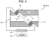
- ultrasonic flowmeter 80 according to the present embodiment will be described using FIG. 4 .
- ultrasonic flowmeter 80 described hereinafter can be replaced with ultrasonic flow velocimeter 81.
- the term "flow rate” in the following description is beneficially replaced with the term "flow velocity".
- a measuring instrument illustrated in FIG. 4 may be capable of measuring both the flow rate and the flow velocity.
- FIG. 4 is a schematic block diagram illustrating a configuration example of ultrasonic flowmeter 80 in the second embodiment.
- ultrasonic flowmeter 80 in the present embodiment is configured such that a pair of ultrasonic transceivers 16 and 17 having the configuration of ultrasonic transceiver 1 described in the first embodiment are disposed on the upstream side and the downstream side of flow path 15, respectively, to face each other.
- An arrow in flow path 15 indicates the direction of the flow of a fluid.
- the left-hand side is the upstream side of flow path 15, while the right-hand side is the downstream side of flow path 15.
- a dashed-line arrow L1 in FIG. 4 indicates a propagation path of an ultrasonic wave propagating from ultrasonic transceiver 16 disposed on the upstream side into ultrasonic transceiver 17.
- Ultrasonic flowmeter 80 in the present embodiment includes: clocking device 18 connected to ultrasonic transceivers 16 and 17 and configured to clock the amount of time elapsed before the arrival of an ultrasonic wave from one of ultrasonic transceivers 16 and 17 at the other; and calculator 19 connected to clocking device 35 and configured to calculate the flow rate of a fluid flowing through flow path 15 by using the amount of ultrasonic arrival time determined by clocking device 18.
- ultrasonic flow velocimeter 81 is configured in the same manner as ultrasonic flowmeter 80, except that calculator 19 is configured to calculate the flow velocity of a fluid flowing through flow path 15, from the amount of ultrasonic arrival time determined by clocking device 18. Note that calculator 19 may be configured to calculate both the flow velocity and flow rate of a fluid flowing through flow path 15.
- V represents the flow velocity of a fluid flowing through flow path 15
- C (not illustrated) represents the velocity of an ultrasonic wave in the fluid
- ⁇ represents an angle between the direction of the flow of the fluid and the direction of propagation of the ultrasonic wave.
- ultrasonic flowmeter 80 includes: flow path 15 allowing a measurement target fluid to flow therethrough; a pair of ultrasonic transceivers 16 and 17 disposed on the upstream side and the downstream side of flow path 15, respectively, to face each other; clocking device 18 configured to clock the amount of arrival time elapsed from transmission of an ultrasonic signal from one of ultrasonic transceivers 16 and 17 to reception of the ultrasonic signal by the other; and calculator 19 configured to calculate the flow rate of the measurement target fluid flowing through flow path 15 from the amount of ultrasonic arrival time determined by clocking device 18. Note that, when the measuring instrument illustrated in FIG.
- ultrasonic flow velocimeter 81 is configured in the same manner as ultrasonic flowmeter 80, except that calculator 19 is configured to calculate the flow velocity of the measurement target fluid flowing through flow path 15 from the amount of ultrasonic arrival time determined by clocking device 18.
- ultrasonic flowmeter 80 or ultrasonic flow velocimeter 81 according to the present disclosure is used in a fluid of high temperature and high humidity or in a high-temperature and high-humidity environment, even when corrosion deterioration occurs in the outer circumference of acoustic matching body 2 and moisture enters closed space 11 from a gap caused by the corrosion deterioration in the outer circumferential portion of acoustic matching body 2, moisture entry can be substantially prevented from spreading in the whole of acoustic matching body 2, because closed space 11 is divided into a plurality of closed spaces by perpendicular partition walls 12.
- ultrasonic flowmeter 80 can stably measure the flow rate of the measurement target fluid with high accuracy.
- ultrasonic flow velocimeter 81 can stably measure the flow velocity of the measurement target fluid with high accuracy.
- FIG. 5 is a schematic block diagram illustrating a configuration example of ultrasonic densitometer 90 in a third embodiment.
- Ultrasonic densitometer 90 according to the present disclosure includes casing 30 including concentration measurement space 37 for measuring a fluid concentration.
- Casing 30 includes vent 31 configured to allow a measurement target fluid to pass out of or into casing 30 through vent 31.
- Concentration measurement space 37 in casing 30 has, for example, a rectangular parallelepiped shape or a cylindrical shape.
- Concentration measurement space 37 is not necessarily entirely surrounded by a wall of casing 30, and is beneficially a space at least capable of transmitting and receiving an ultrasonic wave between the pair of ultrasonic transceivers 32 and 33.
- casing 30 is made partially defective, and, in the defect portion, concentration measurement space 37 may be opened to the outside of casing 30.
- the pair of ultrasonic transceivers 32 and 33 each having the configuration of ultrasonic transceiver 1 described in the first embodiment are disposed to face each other. Furthermore, temperature sensor 34 is accommodated in concentration measurement space 37. Ultrasonic transceivers 32 and 33 are connected to clocking device 35. Clocking device 35 and temperature sensor 34 are connected to calculator 36.
- ultrasonic transceiver 32 When ultrasonic transceiver 32 is used as an ultrasonic transmitter, ultrasonic transceiver 32 transmits an ultrasonic wave, based on the operation of clocking device 35. In this case, ultrasonic transceiver 33 functions as an ultrasonic receiver. The ultrasonic wave transmitted from ultrasonic transceiver 32 propagates through the measurement target fluid filled in concentration measurement space 37. Ultrasonic transceiver 33 used as an ultrasonic receiver receives the ultrasonic wave.
- Clocking device 35 measures a propagation time elapsed from the transmission of an ultrasonic wave from ultrasonic transceiver 32 to the reception of the ultrasonic wave by ultrasonic transceiver 33, and determines the propagation velocity Vs of the ultrasonic wave, based on a predetermined ultrasonic propagation distance L.
- the propagation velocity Vs of an ultrasonic wave propagating through a mixed gas as the measurement target fluid is determined by the average molecular weight M, the specific heat ratio ⁇ , the gas constant R, and the gas temperature T (K) of the mixed gas, as expressed by the following formula (6).
- the average molecular weight is determined.
- Vs ⁇ ⁇ R ⁇ T / M
- the gas temperature T and the propagation velocity Vs are measured to determine the average molecular weight M, whereby a gas concentration can be calculated from the average molecular weight M.
- ma represents the molecular weight of gas a
- mb represents the molecular weight of gas b.
- ultrasonic densitometer 90 includes: casing 30 including a vent allowing a measurement target fluid to pass out of or into casing 30; a pair of ultrasonic transceivers 32 and 33 disposed at a predetermined distance from each other and facing each other in casing 30; temperature sensor 34 disposed inside casing 30; clocking device 3 configured to clock the amount of arrival time elapsed from transmission of an ultrasonic signal from one of the pair of ultrasonic transceivers 32 and 33 to the reception of the ultrasonic signal by the other; and calculator 36 configured to calculate the propagation velocity of the ultrasonic wave propagating through the measurement target fluid, the average molecular weight of a mixed gas, and the gas concentration of the mixed gas, from the amount of arrival time determined by clocking device 35.
- ultrasonic densitometer 90 including ultrasonic transceivers 32 and 33 according to the present disclosure is used in a fluid of high temperature and high humidity or in a high-temperature and high-humidity environment, even when corrosion deterioration occurs in the outer circumference of acoustic matching body 2 and moisture enters closed space 11 from a gap caused by the corrosion deterioration in the circumferential portion of acoustic matching body 2, the spread of moisture entry in the whole of acoustic matching body 2 can be substantially prevented, because closed space 11 is divided into a plurality of closed spaces by perpendicular partition walls 12.
- ultrasonic densitometer 90 can stably measure the gas concentration of the measurement target fluid with high accuracy.
- FIG. 6 is a cross-sectional view of a configuration example of acoustic matching body 20 in the fourth embodiment. Note that (a) of FIG. 6 is a cross-sectional view (a cross-sectional view in the X-Z plane) taken along the thickness direction (parallel to the Z-axis) of acoustic matching body 20. Furthermore, (b) of FIG.
- FIG. 6 is a cross-sectional view taken along line VI-VI illustrated in (a) of FIG. 6 , in other words, a cross-sectional view (a cross-sectional view in the X-Y plane) taken along a direction (parallel to the X-Y plane) perpendicular to the thickness direction of acoustic matching body 20.
- acoustic matching body 20 includes top plate 8, bottom plate 9, side wall 10, perpendicular partition walls 12, and horizontal partition walls 39.
- closed space 11 is defined by top plate 8, bottom plate 9, and side wall 10.
- perpendicular partition walls 12 are formed substantially perpendicularly to top plate 8 and bottom plate 9 (to extend in substantially parallel to the Z-axis), meanwhile horizontal partition walls 39 are formed to be substantially horizontal to top plate 8 and bottom plate 9 (extends substantially horizontally to the X-Y plane) inside closed space 11.
- Perpendicular partition walls 12 are formed to adhere to top plate 8 and bottom plate 9 so that perpendicular partition walls 12 divide closed space 11 into a plurality of closed space when acoustic matching body 20 is viewed from above (viewed in parallel to the Z-axis).
- Horizontal partition walls 39 are formed to adhere to side wall 10 and perpendicular partition walls 12 so that horizontal partition walls 39 divide closed space 11 into upper and lower parts (along the Z-axis) when acoustic matching body 20 is viewed horizontally (viewed in parallel to the X-axis and the Y-axis).
- closed space 11 is partitioned into a plurality of spaces by perpendicular partition walls 12 and horizontal partition walls 39.
- acoustic matching body 20 in the fourth embodiment includes: two perpendicular partition walls 12 disposed concentrically and eight perpendicular partition walls 12 disposed to extend linearly and radially, when acoustic matching body 20 is viewed from above (in parallel to the Z-axis); and two disc-shaped horizontal partition walls 39.
- closed space 11 is partitioned into three circular closed spaces and 48 sector-shaped closed spaces.
- the shape and number of perpendicular partition walls 12 and horizontal partition walls 39 disposed in closed space 11 are not limited to the shape and number illustrated in FIG. 6 . Other examples of the shape of the perpendicular partition walls will be described later.
- FIG. 7 is a diagram illustrating the procedure for manufacturing acoustic matching body 20 in the fourth embodiment by using perspective views. The steps for manufacturing acoustic matching body 20 are performed in the order of (a), (b), (c), and (d) illustrated in FIG. 7 .
- metal plate 13 As illustrated in (a) of FIG. 7 , first, one or a plurality of metal plates 13 large enough to cut out a plurality of metal plates 14a and 14b is prepared.
- (a) of FIG. 7 illustrates one metal plate 13.
- metal plate 13 is circularly patterned to produce a plurality of metal plates 14a serving as top plate 8, bottom plate 9, and horizontal partition walls 39, and furthermore, a plurality of metal plates 14b patterned with perpendicular partition walls 12 and side wall 10 that are formed substantially perpendicularly to top plate 8 and bottom plate 9 of acoustic matching body 2 is produced from metal plate 13.
- metal plate 13 for example, punching of metal plate 13 with a press, etching by photolithography, laser processing, or processing using an electric discharge wire can be applied.
- the above-described steps are the same as the steps described using (a) and (b) of FIG. 3 in the first embodiment, and the shapes of the metal plates 14a and 14b are also the same as those described in the first embodiment.
- metal plates 14a and metal plates 14b are positioned and alternately laminated. Specifically, metal plates 14a are laminated as horizontal partition walls 39 meanwhile metal plates 14b are laminated as perpendicular partition walls 12. Then, metal plate 14a serving as top plate 8 is laminated on the top face of alternately laminated metal plates 14a and 14b (a face on the Z-axis positive direction side of metal plate 14b disposed at an end in the Z-axis positive direction). Next, metal plate 14a serving as bottom plate 9 is laminated on the bottom face of alternately laminated metal plates 14a and 14b (a face on the Z-axis negative direction side of metal plate 14b disposed at an end in the Z-axis negative direction).
- the patterned metal plates are joined by heating and pressurization to become an integrated member by diffusion joining.
- the heating temperature in the case of stainless having a melting point of approximately 1500°C, the temperature in the diffusion joining is approximately 1000°C, and therefore, when alternately laminated metal plates 14a and 14b are made of stainless steel, laminated metal plates 14a and 14b are heated to the above-mentioned temperature and pressurized to perform diffusion joining.
- flatness is required, and therefore, depending on the way of processing illustrated in (c) of FIG. 7 , post-processing is needed to eliminate burrs or deformations of metal plates 14a and 14b after the step illustrated in (b) of FIG. 7 .
- acoustic matching body 20 in the fourth embodiment in which patterned metals are joined by diffusion joining can be produced as illustrated in (d) of FIG. 7 .
- acoustic matching body 20 of the ultrasonic transceiver in the present embodiment includes top plate 8, bottom plate 9, and side wall 10 that define closed space 11, and further includes perpendicular partition walls 12 formed substantially perpendicularly to top plate 8 and bottom plate 9 inside closed space 11, and horizontal partition walls 39 formed substantially horizontally to top plate 8 and bottom plate 9 inside closed space 11.
- Perpendicular partition walls 12 adhere to top plate 8 and bottom plate 9, thereby dividing closed space 11, meanwhile horizontal partition walls 39 adhere to side wall 10 and perpendicular partition walls 12 to divide closed space 11 into upper and lower parts (along the Z-axis).
- the ultrasonic transceiver including acoustic matching body 20 is used in a fluid of high temperature and high humidity or in a high-temperature and high-humidity environment, even when corrosion deterioration occurs in the outer circumference of acoustic matching body 20 and moisture enters closed space 11 from a gap caused by the corrosion deterioration in the outer circumferential portion of acoustic matching body 20, the spread of moisture entry in the whole of acoustic matching body 20 can be substantially prevented, because closed space 11 is divided into a plurality of closed spaces by perpendicular partition walls 12 and horizontal partition walls 39.
- acoustic matching body 20 used in the ultrasonic transceiver according to the present disclosure closed space 11 is partitioned by perpendicular partition walls 12 and horizontal partitions 39, and hence, closed space 11 is divided into more closed spaces than that in acoustic matching body 2 in the first embodiment. Therefore, the ultrasonic transceiver including acoustic matching body 20 is capable of stably operating for a still longer period.
- the method for manufacturing acoustic matching body 20 is such that the step of forming a pattern in metal plate 13, the step of alternately laminating patterned metal plates 14a and 14b, and the step of joining metal plates 14a and 14b by applying a load at a high temperature are performed in this order.
- acoustic matching body 20 can be patterned with high accuracy and the metal plates can be firmly joined without a gap, whereby the acoustic matching body can be stably manufactured with high accuracy.
- the ultrasonic transceiver can be manufactured with less variation in quality in mass production.
- the ultrasonic transceiver according to the present embodiment can be used as an ultrasonic transceiver used of ultrasonic flowmeter 80 or ultrasonic flow velocimeter 81 described in the second embodiment or ultrasonic densitometer 90 described in the third embodiment.
- a different shape of pattern of perpendicular partition wall 12 from the shapes illustrated in FIGS. 2 , 3 , 6 , and 7 will be illustrated.
- the acoustic matching body described in the present embodiment is the same as acoustic matching bodies 2 and 20 respectively described in the first embodiment and the fourth embodiment, except the pattern of perpendicular partition wall 12, and therefore, descriptions on the configuration, except on the pattern of perpendicular partition wall 12 will be omitted.
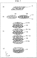
- FIG. 8 is a cross-sectional view of a configuration example of the acoustic matching body in the fifth embodiment.
- FIG. 9 is a cross-sectional view of another configuration example of the acoustic matching body in the fifth embodiment.
- FIGS. 8 and 9 are cross-sectional views (cross-sectional views in the X-Y plane) taken along a direction (parallel to the X-Y plane) perpendicular to the thickness direction of the acoustic matching body.
- FIGS. 8 and 9 side wall 10, and perpendicular partition walls 12 formed substantially perpendicularly to top plate 8 and bottom plate 9 of the acoustic matching body are illustrated.
- the pattern of perpendicular partition wall 12 can be arbitrarily selected according to an usage environment or a required strength, and examples of the pattern include a lattice shape illustrated in FIG. 8 and a honeycomb shape illustrated in FIG. 9 .
- a pattern in which circles are spread around can be selected for perpendicular partition wall 12.
- perpendicular partition wall 12 defined inside closed space 11 of the acoustic matching body is preferably thinner than the thickness of side wall 10. As the acoustic matching body is lighter in weight, the acoustic matching body can more efficiently transmit an ultrasonic wave to a measurement target fluid. Therefore, perpendicular partition wall 12 is preferably thinner than top plate 8 and bottom plate 9, and the number of perpendicular partition walls 12 is preferably smaller. However, when used in a high-temperature and high-humidity environment, corrosion deterioration begins in side wall 10. Therefore, by making side wall 10 larger in thickness, corrosion resistance is enhanced.
- perpendicular partition walls 12 defined inside closed space 11 of the acoustic matching body is made thinner than side wall 10, whereby, while substantially preventing a decrease in the propagation efficiency of an ultrasonic wave, the resistance of the acoustic matching body to a high-temperature and high-humidity environment in which the acoustic matching body easily corrodes can be enhanced.
- Perpendicular partition wall 12 has the function of partitioning closed space 11, and also functions as a frame that resonates with ultrasonic vibration generated in piezoelectric body 3.
- Perpendicular partition wall 12 and top plate 8 are firmly joined by diffusion joining. However, when the area of each region obtained by the partition by perpendicular partition walls 12 is larger, top plate 8 is bent, and accordingly, a vibration different from a targeted vibration occurs, whereby the efficiency of propagation of an ultrasonic wave to the measurement target fluid falls as a result.
- Table 1 illustrates a relation among the area (mm 2 ) of a region resulting from partition by perpendicular partition walls 12 in the acoustic matching body, the projected area ratio (%) of perpendicular partition walls 12, and the efficiency of ultrasonic propagation.
- the projected area ratio (%) of perpendicular partition walls 12 means the ratio of the total area of perpendicular partition walls 12 to the area of the acoustic matching body except side wall 10, when the acoustic matching body is viewed from above (viewed in parallel to the Z-axis).
- the projected area ratio (%) of perpendicular partition walls 12 is larger, perpendicular partition wall 12 is larger in thickness or the number of perpendicular partition walls 12 is larger.
- An area (an area when the acoustic matching body is viewed from above (viewed in parallel to the Z-axis)) of a region resulting from perpendicular partition walls 12 is preferably 0.2 mm 2 or larger, and more preferably in a range of 0.30 mm 2 to 1.0 mm 2 .
- the projected area ratio of perpendicular partition walls 12 is preferably 15% or lower, and more preferably in a range of 8% to 13%.
- top plate 8 of the acoustic matching body When the thickness of top plate 8 of the acoustic matching body is thinner than the thickness of one patterned metal plate (for example, metal plate 13), the efficiency of ultrasonic propagation into a measurement target fluid can be enhanced.
- perpendicular partition walls 12 defined formed inside closed space of the acoustic matching body are thinner than side wall 10.
- the resistance of the ultrasonic transceiver to a high-temperature and high-humidity environment in which the acoustic matching body easily corrodes can be enhanced.
- the area of each region resulting from partition by perpendicular partition walls 12 (the area of the region when the acoustic matching body is viewed from above (viewed in parallel to the Z-axis)) is 1 mm 2 or smaller
- the projected area of perpendicular partition walls 12 (the total area of perpendicular partition walls 12 when the acoustic matching body is viewed from above (viewed in parallel to the Z-axis)) is 10% or less of the projected area of the acoustic matching body except side wall 10 (the area of the acoustic matching body except side wall 10 when the acoustic matching body is viewed from above (viewed in parallel to the Z-axis)).
- the efficiency of propagation of an ultrasonic wave from the ultrasonic transceiver including the acoustic matching body into a measurement target fluid can be further enhanced.
- the acoustic matching body is formed by laminating a plurality of patterned metal plates.
- perpendicular partition wall 12 having a more complicated shape can be produced with high definition.
- variations in characteristics can be reduced.
- measurement with high accuracy can be achieved.
- the acoustic matching body is formed so that top plate 8 is thinner than one patterned metal plate (for example, metal plate 13).
- the efficiency of ultrasonic propagation from the ultrasonic transceiver including the acoustic matching body into a measurement target fluid can be further enhanced.
- the ultrasonic transceiver according to the present embodiment can be used as an ultrasonic transceiver of ultrasonic flowmeter 80 or ultrasonic flow velocimeter 81 described in the second embodiment or ultrasonic densitometer 90 described in the third embodiment.
- FIGS. 10 to 12 a sixth embodiment will be described using FIGS. 10 to 12 .
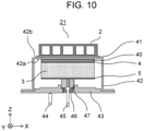
- FIG. 10 is a cross-sectional view of a configuration example of ultrasonic transceiver 21 in the sixth embodiment.
- FIG. 10 is a cross-sectional view (a cross-sectional view in the X-Z plane) taken along the thickness direction (parallel to the Z-axis) of ultrasonic transceiver 21.
- ultrasonic transceiver 21 includes: closed-top tubular metal case 42; piezoelectric body 3 disposed in top inner wall 42a of closed-top tubular metal case 42; and acoustic matching body 2 described in the first embodiment or acoustic matching body 20 described in the fourth embodiment, which is disposed in top outer wall 42b of closed-top tubular metal case 42.
- Top inner wall 42a is a top face on the inner side (a face on the Z-axis negative direction side) of closed-top tubular metal case 42
- top outer wall 42b is a top face on the outer side (a face on the Z-axis positive direction side) of closed-top tubular metal case 42.
- Terminal 44 is the equivalent of lead wire 6 illustrated in FIG.
- Terminal 45 is the equivalent of lead wire 7 illustrated in FIG. 1 and is electrically connected to electrode 5 of piezoelectric body 3 via conductive rubber 47.
- Through-hole 46 provided in terminal plate 43 is a hole for allowing terminal 45 to penetrate, and terminal 45 penetrates through-hole 46 upward from the bottom (in substantially parallel to the Z-axis), and comes into contact with a conductive center of conductive rubber 47.
- acoustic matching body 2 is assumed to be joined to top outer wall 42b of closed-top tubular metal case 42, but, acoustic matching body 2 may be replaced with acoustic matching body 20. In that case, descriptions may be the same as the following descriptions, and therefore will be omitted.
- an organic adhesive, low melting glass, soldering, or brazing can be used for the joining of closed-top tubular metal case 42 to acoustic matching body 2 and piezoelectric body 3.
- FIG. 11 is a diagram illustrating the procedure for manufacturing ultrasonic transceiver 21 in the sixth embodiment by using cross-sectional views.
- acoustic matching body 2 described in the first embodiment is prepared.
- a thermosetting adhesive to be used as joining material 40 is applied to the upper face (a face on the Z-axis positive direction side) of piezoelectric body 3, and the same joining material 41 is applied to top outer wall 42b of closed-top tubular metal case 42.
- joining material 41 is applied to top outer wall 42b of closed-top tubular metal case 42.
- closed-top tubular metal case 42 is laminated on piezoelectric body 3, and joining material 40 is interposed between the upper face (a face in the Z-axis positive direction side) of piezoelectric body 3 and top inner wall 42a of closed-top tubular metal case 42 to paste the upper face and top inner wall 42a together.
- acoustic matching body 2 is laminated on closed-top tubular metal case 42, and joining material 41 is interposed between top outer wall 42b of closed-top tubular metal case 42 and the lower face (a face in the Z-axis negative direction side) of acoustic matching body 2 to paste the upper face and top inner wall 42a together.
- piezoelectric body 3, closed-top tubular metal case 42, and acoustic matching body 2 are heated while being pressurized at approximately 2 kg/cm 2 to 10 kg/cm 2 , whereby the thermosetting adhesive is cured.
- acoustic matching body 2 and piezoelectric body 3 are stuck fast to closed-top tubular metal case 42.
- terminal plate 43 in which conductive rubber 47 is inserted into a recessed portion provided above through-hole 46 is superimposed on a joined member from below, the joined member including acoustic matching body 2, closed-top tubular metal case 42, and piezoelectric body 3 and being obtained by heat-curing and laminating through the above-described steps.
- a flange of closed-top tubular metal case 42 and a circumferential edge portion of terminal plate 43 are welded.
- an inert gas such as argon gas, nitrogen gas, or helium gas, is sealed in a closed space surrounded by terminal plate 43 and closed-top tubular metal case 42.
- terminal 44 is joined to terminal plate 43, and terminal 45 is brought into contact with a center portion of conductive rubber 47.
- a material for forming closed-top tubular metal case 42 is beneficially iron, brass, copper, aluminum, stainless steel, or an alloy thereof, or a conductive material such as a metal obtained by plating a surface of the above-mentioned metals.
- thermosetting adhesive used as joining materials 40 and 41 is beneficially a thermosetting resin, such as an epoxy resin, a phenolic resin, a polyester resin or, a melamine resin, and is not particularly limited.
- a thermoplastic resin having a glass-transition temperature that is equal to or higher than a high-temperature use temperature (for example, 70°C or higher), the high-temperature use temperature being a temperature defined as the upper limit of an operating temperature of ultrasonic transceiver 21.
- ultrasonic transceiver 21 is in a finished state.
- FIG. 12 is a cross-sectional view and a plan view of a configuration example of ultrasonic transceiver 21 in the sixth embodiment.
- (a) of FIG. 12 is a cross-sectional view (a cross-sectional view in the X-Z plane) taken along the thickness direction (parallel to the Z-axis) of ultrasonic transceiver 21.
- (b) of FIG. 12 is a plan view obtained when ultrasonic transceiver 21 is viewed from above (viewed in parallel to the Z-axis).
- a relation between a projected plane of joint in piezoelectric body 3 and a projected plane of joint in side wall 10 in the sixth embodiment is illustrated.
- the projected plane of joint in piezoelectric body 3 is a joint face between piezoelectric body 3 and top inner wall 42a when ultrasonic transceiver 21 is viewed from above (viewed in parallel to the Z-axis).
- the projected plane of joint in side wall 10 is a joint face between side wall 10 and top outer wall 42b when ultrasonic transceiver 21 is viewed from above (viewed in parallel to the Z-axis).
- the projected plane of joint in piezoelectric body 3 is referred to as piezoelectric body joint projected plane 48
- the projected plane of joint of side wall 10 of acoustic matching body 2 is referred to as side wall joint projected plane 49.
- Piezoelectric body 3 vibrates at a predetermined frequency by an ultrasonic signal, and acoustic matching body 2 resonates to this vibration, whereby an ultrasonic signal having a higher amplitude is produced.
- an ultrasonic wave propagates from ultrasonic transceiver 21 into a measurement target fluid.
- the measurement target fluid is assumed to be a fluid of high temperature and high humidity.
- closed space 11 is defined by top plate 8, bottom plate 9, and side wall 10
- perpendicular partition walls 12 formed substantially perpendicularly to top plate 8 and bottom plate 9 are provided inside closed space 11.
- Perpendicular partition walls 12 are formed to adhere to top plate 8 and bottom plate 9 so that perpendicular partition wall 12 and side wall 10 divide closed space 11.
- the thickness of side wall 10 is preferably 0.3 mm or more in order to further enhance the moisture resistance of acoustic matching body 2.
- acoustic matching body 2 causes acoustic matching body 2 to be larger in weight, whereby there is a risk of a decrease in the efficiency of propagation of ultrasonic waves into the measurement target fluid.
- piezoelectric body 3 and acoustic matching body 2 are formed so that the projected plane of joint of piezoelectric body 3 to closed-top tubular metal case 42, namely, piezoelectric body joint projected plane 48 is included in side wall joint projected plane 49 of acoustic matching body 2. It was confirmed that, with this configuration, a decrease in the efficiency of ultrasonic propagation from ultrasonic transceiver 21 into the measurement target fluid can be substantially prevented. Thus, with this configuration, while a decrease in the efficiency of propagation of ultrasonic waves is substantially prevented, the thickness of side wall 10 can be 0.3 mm or more, whereby the moisture resistance of acoustic matching body 2 can be further enhanced.
- ultrasonic transceiver 21 is configured to include: closed-top tubular metal case 42; piezoelectric body 3 disposed in top inner wall 42a of closed-top tubular metal case 42; and acoustic matching body 2 described in the first embodiment and disposed in top outer wall 42b of closed-top tubular metal case 42.
- ultrasonic transceiver 21 may be configured to include acoustic matching body 20 described in the fourth embodiment, in place of acoustic matching body 2.
- ultrasonic transceiver 21 in the case where ultrasonic transceiver 21 according to the present disclosure is used in a fluid of high temperature and high humidity or in a high-temperature and high-humidity environment, even when corrosion deterioration occurs in the outer circumference of acoustic matching body 2 (or acoustic matching body 20) and moisture enters closed space 11 from a gap caused by the corrosion deterioration in the outer circumferential portion of acoustic matching body 2 (or acoustic matching body 20), the spread of moisture entry in the whole of acoustic matching body 2 (or acoustic matching body 20) can be substantially prevented, because closed space 11 is partitioned into a plurality of closed spaces by perpendicular partition walls 12 (or perpendicular partition walls 12 and horizontal partition walls 39).
- ultrasonic transceiver 21 can stably operate for a long period.
- piezoelectric body 3 is sealed by closed-top tubular metal case 42 and terminal plate 43, so that corrosion of electrodes 4 and 5 of piezoelectric body 3 and deterioration of joining material 40 are inhibited.
- the reliability of the measuring instrument including ultrasonic transceiver 21 is secured for a long period.
- piezoelectric body 3 and acoustic matching body 2 are formed so that piezoelectric body joint projected plane 48 is included in side wall joint projected plane 49 of acoustic matching body 2 (or acoustic matching body 20).
- Ultrasonic transceiver 21 can be used as an ultrasonic transceiver of ultrasonic flowmeter 80 or ultrasonic flow velocimeter 81 described in the second embodiment or ultrasonic densitometer 90 described in the third embodiment.
- FIG. 13A is a cross-sectional view illustrating a configuration example of ultrasonic transceiver 23 in the seventh embodiment.
- ultrasonic transceiver 23 includes: piezoelectric body 3; closed-top tubular metal case 42 disposed in one face of piezoelectric body 3; and acoustic matching body 22 disposed in top outer wall 42b of closed-top tubular metal case 42.
- acoustic matching body 22 in the present embodiment does not include bottom plate 9, and top outer wall 42b of closed-top tubular metal case 42 is used in place of bottom plate 9.
- closed space 11 is defined by top plate 8, side wall 10, and top outer wall 42b of closed-top tubular metal case 42.
- perpendicular partition walls 12 formed substantially perpendicularly to top plate 8 of acoustic matching body 22 and top outer wall 42b of closed-top tubular metal case 42.
- Perpendicular partition walls 12 adhere to top plate 8 of acoustic matching body 22 and top outer wall 42b of closed-top tubular metal case 42 via joining material 41 described in the sixth embodiment so as to divide closed space 11.
- Acoustic matching body 22 in the present embodiment is configured by eliminating bottom plate 9 from acoustic matching bodies 2 and 20 respectively illustrated in the first and fourth embodiments, and this configuration allows acoustic matching body 22 to be lighter in weight than acoustic matching bodies 2 and 20.
- the efficiency of propagation of ultrasonic waves from ultrasonic transceiver 23 including acoustic matching body 22 into a measurement target fluid can be further enhanced.
- acoustic matching body 22 is configured in substantially the same manner as acoustic matching bodies 2 and 20, except that acoustic matching body 22 does not include bottom plate 9.
- an inner space is defined by top plate 8 and side wall 10, and an edge of side wall 10, the edge being more distant from top plate 8 (an end on the Z-axis negative direction side), adheres to top outer wall 42b of closed-top tubular metal case 42 to define closed space 11.
- acoustic matching body 22 is configured in substantially the same manner as acoustic matching bodies 2 and 20, and therefore detailed descriptions thereof will be omitted.
- a procedure for manufacturing ultrasonic transceiver 23 in the present embodiment is the same as the procedure for manufacturing ultrasonic transceiver 21 illustrated in FIG. 11 in the sixth embodiment, except that acoustic matching body 22 does not include bottom plate 9, and therefore descriptions about the procedure will be omitted.
- an operation of ultrasonic flowmeter 80, an operation of ultrasonic flow velocimeter 81, and an operation of ultrasonic densitometer 90, each including ultrasonic transceiver 23 in the present embodiment are the same as the operations described in the second and third embodiments, and therefore, descriptions about the operations will be omitted.
- ultrasonic transceiver 23 includes: piezoelectric body 3; closed-top tubular metal case 42 disposed in one face of piezoelectric body 3; and acoustic matching body 2 disposed in top outer wall 42b of closed-top tubular metal case 42.
- closed space 11 is defined by top plate 8, side wall 10, top outer wall 42b of closed-top tubular metal case 42, and perpendicular partition walls 12 formed substantially perpendicularly to top plate 8 of acoustic matching body 22 and top outer wall 42b of closed-top tubular metal case 42 are provided inside closed space 11.
- Perpendicular partition walls 12 adhere to top plate 8 of acoustic matching body 22 and top outer wall 42b of closed-top tubular metal case 42, thereby dividing closed space 11.
- ultrasonic transceiver 23 allows ultrasonic transceiver 23 to be lighter in weight by the weight of eliminated bottom plate 9 than ultrasonic transceiver 21 described in the sixth embodiment.
- the efficiency of propagation of ultrasonic waves from ultrasonic transceiver 23 into a measurement target fluid can be further enhanced.
- FIG. 13B is a cross-sectional view of another configuration example of the ultrasonic transceiver in the seventh embodiment.
- ultrasonic transceiver 23 is configured by joining acoustic matching body 22 to top outer wall 42b of closed-top tubular metal case 42 by using joining material 41 is illustrated in FIG. 13A .
- ultrasonic transceiver 25 similar to ultrasonic transceiver 23 can be configured without using joining material 41.
- FIG. 13A an example in which, as described above, ultrasonic transceiver 23 is configured by joining acoustic matching body 22 to top outer wall 42b of closed-top tubular metal case 42 by using joining material 41.
- ultrasonic transceiver 25 may be produced in a manner that acoustic matching body 24 similar to acoustic matching body 22 is used and closed-top tubular metal case 42 and acoustic matching body 24 are integrated so that the top face of closed-top tubular metal case 42 also serves as bottom plate 9 of acoustic matching body 24.
- FIG. 13C is a diagram illustrating a procedure for manufacturing ultrasonic transceiver 25 in the seventh embodiment by using cross-sectional views.
- metal plate 14a serving as top plate 8 is laminated on a plurality of metal plates 14b patterned with side wall 10 and perpendicular partition walls 12. Furthermore, as illustrated in (a) of FIG. 13C , a metal plate produced to have a size corresponding to the shape of closed-top tubular metal case 42 is laminated as bottom plate 9. Then, the laminated metal plates are integrated by diffusion joining. Next, illustrated in (a') of FIG. 13C , bottom plate 9 is formed in the shape of closed-top tubular metal case 42 by pressing. At the same time, as illustrated in (b) of FIG. 13C , piezoelectric body 3 is prepared.
- ultrasonic transceiver 25 is produced by using the procedure illustrated in (c), (d), and (e) of FIG. 13C .
- (c), (d), and (e) of FIG. 13C are the same as (c), (d), and (e) of FIG. 11 , and therefore descriptions thereof will be omitted.
- FIG. 14A and FIG. 14B an eighth embodiment will be described using FIG. 14A and FIG. 14B .
- Acoustic matching body 26 described in the present embodiment is different only in the internal structure from acoustic matching body 2 described in the first embodiment, and has substantially the same configuration as that of acoustic matching body 2, except the internal structure. Furthermore, the configuration of the ultrasonic transceiver in the present embodiment is also the same as that in the first, sixth, and seventh embodiments, and therefore descriptions thereof will be omitted.
- FIG. 14A is a cross-sectional view of a configuration example of acoustic matching body 26 in the eighth embodiment.
- (a) of FIG. 14 is a cross-sectional view (a cross-sectional view in the X-Z plane) taken along the thickness direction (parallel to the Z-axis) of acoustic matching body 26.
- (b) of FIG. 14 is a cross-sectional view taken along line XA-XA illustrated in (a) of FIG. 14(A) , in other words, a cross-sectional view (a cross-sectional view in the X-Y plane) taken along a direction (parallel to the X-Y plane) perpendicular to the thickness direction of acoustic matching body 26.
- acoustic matching body 26 includes top plate 8, bottom plate 9, side wall 10, perpendicular partition walls 12, and horizontal partition walls 39.
- closed space 11 is defined by top plate 8, bottom plate 9, and side wall 10.
- perpendicular partition walls 12 are formed substantially perpendicularly to top plate 8 and bottom plate 9 (extends in substantially parallel to the Z-axis), meanwhile horizontal partition walls 39 are formed substantially horizontally to top plate 8 and bottom plate 9 (extends in substantially parallel to the X-Y plane).
- Perpendicular partition walls 12 are formed to adhere to top plate 8 and bottom plate 9, thereby dividing closed space 11 into a plurality of closed spaces when acoustic matching body 26 is viewed from above (in parallel to the Z-axis).
- Horizontal partition walls 39 are formed to adhere to side wall 10 and perpendicular partition walls 12, thereby dividing closed space 11 into upper and lower parts (along the Z-axis) when acoustic matching body 26 is viewed horizontally (in parallel to the X-axis and the Y-axis).
- the thickness of the partition walls (hereinafter, simply referred to as “the thickness”) is thinner in top portion 28 of acoustic matching body 26 than in bottom portion 29 of acoustic matching body 26.
- the thickness of perpendicular partition wall 12 is gradually thinner from the lower part (the bottom plate 9 side) to the upper part (the top plate 8 side).
- the closed spaces resulting from the division by perpendicular partition walls 12 are gradually larger from the lower portion (the bottom plate 9 side) to the upper portion (the top plate 8 side).
- a procedure for manufacturing acoustic matching body 26 in the present embodiment is the same as the procedure for manufacturing acoustic matching body 20 described in the fourth embodiment by using FIG. 7 , and therefore descriptions of the procedure will be omitted.
- a procedure for manufacturing the ultrasonic transceiver in the present embodiment is the same as the procedure for manufacturing ultrasonic transceiver 21 described in the sixth embodiment by using FIG. 11 , and therefore descriptions thereof will be omitted.
- an operation of ultrasonic flowmeter 80, an operation of ultrasonic flow velocimeter 81, and an operation of ultrasonic densitometer 90 in the present embodiment are the same as the operations described in the second and third embodiments, and therefore, descriptions thereof will be omitted.
- acoustic matching body 26 includes top plate 8, bottom plate 9, and side wall 10 that define closed space 11, and further includes: perpendicular partition walls 12 formed substantially perpendicularly to top plate 8 and bottom plate 9 inside closed space 11; and horizontal partition walls 39 formed horizontally to top plate 8 and bottom plate 9 inside closed space 11.
- Perpendicular partition walls 12 are formed to adhere to top plate 8 and bottom plate 9, thereby dividing closed space 11, meanwhile horizontal partition walls 39 are formed to adhere to side wall 10 and perpendicular partition walls 12, thereby dividing closed space 11 into upper and lower parts (along the Z-axis).
- perpendicular partition walls 12 are formed to be gradually thinner in top portion 28 of acoustic matching body 2 than in bottom portion 29 of acoustic matching body 2.
- the manufacturing method in which metal plates are freely patterned and laminated as described in the first and seventh embodiments is selected, whereby the thickness of perpendicular partition walls 12 formed substantially perpendicularly to top plate 8 and bottom plate 9 can be arbitrarily controlled, depending on a perpendicular position (a position on the Z-axis).
- the apparent density of acoustic matching body 26 can be successively reduced in the ultrasonic propagation direction.
- this allows a designed acoustic impedance of acoustic matching body 26 to be closer to a theoretical value.
- the efficiency of propagation of ultrasonic waves from the ultrasonic transceiver using acoustic matching body 26 into a measurement target fluid can be enhanced.
- the resistance of the ultrasonic transceiver to a high-temperature and high-humidity environment in which the acoustic matching body easily corrodes can be enhanced.
- FIG. 14B is a cross-sectional view of another configuration example of the acoustic matching body in the eighth embodiment.
- (a) of FIG. 14B is a cross-sectional view of acoustic matching body 27 taken along the thickness direction (parallel to the Z-axis)
- (b) of FIG. 14B is a cross-sectional view taken along line XB-XB in (a) of FIG. 14B .
- acoustic matching body 27 may be configured such that horizontal partition walls 39 are eliminated from acoustic matching body 26 illustrated in FIG. 14A , and closed space 11 is divided only by perpendicular partition walls 12. Also in this case, the same effects as those achieved by acoustic matching body 26 illustrated in FIG. 14A can be obtained.
- the present disclosure is applicable to an ultrasonic flowmeter, an ultrasonic flow velocimeter, and an ultrasonic densitometer that are respectively configured to measure the flow rate, the flow velocity, and the concentration of gas.
- the present disclosure is applicable to, for example, a home flowmeter, a medical anesthetic gas densitometer, and a hydrogen densitometer for fuel cells.
Landscapes
- Physics & Mathematics (AREA)
- General Physics & Mathematics (AREA)
- Fluid Mechanics (AREA)
- Electromagnetism (AREA)
- Acoustics & Sound (AREA)
- Life Sciences & Earth Sciences (AREA)
- General Health & Medical Sciences (AREA)
- Health & Medical Sciences (AREA)
- Pathology (AREA)
- Chemical & Material Sciences (AREA)
- Analytical Chemistry (AREA)
- Biochemistry (AREA)
- Immunology (AREA)
- Engineering & Computer Science (AREA)
- Mechanical Engineering (AREA)
- Multimedia (AREA)
- Measuring Volume Flow (AREA)
- Investigating Or Analyzing Materials By The Use Of Ultrasonic Waves (AREA)
- Transducers For Ultrasonic Waves (AREA)
Applications Claiming Priority (2)
| Application Number | Priority Date | Filing Date | Title |
|---|---|---|---|
| JP2020067176A JP7573192B2 (ja) | 2020-04-03 | 2020-04-03 | 超音波送受波器並びに超音波流量計、超音波流速計、超音波濃度計、及び製造方法 |
| PCT/JP2021/013500 WO2021200925A1 (fr) | 2020-04-03 | 2021-03-30 | Émetteur-récepteur à ultrasons, débitmètre à ultrasons, vélocimètre à ultrasons, densitomètre à ultrasons et procédé de fabrication |
Publications (2)
| Publication Number | Publication Date |
|---|---|
| EP4132006A1 true EP4132006A1 (fr) | 2023-02-08 |
| EP4132006A4 EP4132006A4 (fr) | 2023-09-06 |
Family
ID=77928929
Family Applications (1)
| Application Number | Title | Priority Date | Filing Date |
|---|---|---|---|
| EP21778959.3A Pending EP4132006A4 (fr) | 2020-04-03 | 2021-03-30 | Émetteur-récepteur à ultrasons, débitmètre à ultrasons, vélocimètre à ultrasons, densitomètre à ultrasons et procédé de fabrication |
Country Status (5)
| Country | Link |
|---|---|
| US (1) | US12270693B2 (fr) |
| EP (1) | EP4132006A4 (fr) |
| JP (1) | JP7573192B2 (fr) |
| CN (1) | CN115398937A (fr) |
| WO (1) | WO2021200925A1 (fr) |
Families Citing this family (1)
| Publication number | Priority date | Publication date | Assignee | Title |
|---|---|---|---|---|
| JP7595309B2 (ja) * | 2022-02-22 | 2024-12-06 | パナソニックIpマネジメント株式会社 | 振動伝搬部材、およびこれを用いた送受波器、流体種類判別装置 |
Family Cites Families (17)
| Publication number | Priority date | Publication date | Assignee | Title |
|---|---|---|---|---|
| JP2001349757A (ja) * | 2000-06-12 | 2001-12-21 | Matsushita Electric Ind Co Ltd | 超音波振動子とこれを用いた超音波流量計 |
| JP2002135894A (ja) | 2000-10-26 | 2002-05-10 | Murata Mfg Co Ltd | 超音波センサ及びそれを用いた電子装置 |
| JP4439769B2 (ja) * | 2001-09-05 | 2010-03-24 | パナソニック株式会社 | 音響整合部材 |
| JP2004343263A (ja) * | 2003-05-14 | 2004-12-02 | Matsushita Electric Ind Co Ltd | 音響整合部材およびその製造方法 |
| JP2005037219A (ja) * | 2003-07-14 | 2005-02-10 | Matsushita Electric Ind Co Ltd | 超音波送受波器及びその製造方法 |
| JP4702349B2 (ja) * | 2007-10-24 | 2011-06-15 | パナソニック株式会社 | 超音波送受波器とそれを使用した超音波流れ測定装置 |
| JP4857296B2 (ja) * | 2008-03-07 | 2012-01-18 | パナソニック株式会社 | 音響整合体 |
| JP2010268262A (ja) | 2009-05-15 | 2010-11-25 | Panasonic Corp | 音響整合体およびそれを備えた超音波送受波器 |
| JP2016153750A (ja) * | 2015-02-20 | 2016-08-25 | 日清紡ホールディングス株式会社 | 気体濃度センサ |
| JP6536792B2 (ja) * | 2015-03-25 | 2019-07-03 | セイコーエプソン株式会社 | 超音波センサー及びその製造方法 |
| WO2017212511A1 (fr) * | 2016-06-09 | 2017-12-14 | パナソニックIpマネジメント株式会社 | Stratifié, transducteur ultrasonore, et débitmètre à ultrasons |
| JP6032512B1 (ja) * | 2016-06-09 | 2016-11-30 | パナソニックIpマネジメント株式会社 | 積層体、超音波送受波器および超音波流量計 |
| JP6663031B2 (ja) * | 2016-10-13 | 2020-03-11 | 富士フイルム株式会社 | 超音波探触子および超音波探触子の製造方法 |
| JP2018093380A (ja) * | 2016-12-05 | 2018-06-14 | セイコーエプソン株式会社 | 超音波デバイスの製造方法、超音波プローブの製造方法、電子機器の製造方法及び超音波画像装置の製造方法 |
| JP6832152B2 (ja) * | 2016-12-21 | 2021-02-24 | 上田日本無線株式会社 | 気体濃度測定装置およびその校正方法 |
| JP7108816B2 (ja) * | 2017-06-30 | 2022-07-29 | パナソニックIpマネジメント株式会社 | 音響整合層 |
| JP6954866B2 (ja) * | 2018-06-08 | 2021-10-27 | 株式会社日立製作所 | 音響整合デバイスおよびそれを用いた音響プローブシステム |
-
2020
- 2020-04-03 JP JP2020067176A patent/JP7573192B2/ja active Active
-
2021
- 2021-03-30 WO PCT/JP2021/013500 patent/WO2021200925A1/fr not_active Ceased
- 2021-03-30 EP EP21778959.3A patent/EP4132006A4/fr active Pending
- 2021-03-30 US US17/916,276 patent/US12270693B2/en active Active
- 2021-03-30 CN CN202180025660.3A patent/CN115398937A/zh active Pending
Also Published As
| Publication number | Publication date |
|---|---|
| JP2021164128A (ja) | 2021-10-11 |
| US12270693B2 (en) | 2025-04-08 |
| JP7573192B2 (ja) | 2024-10-25 |
| EP4132006A4 (fr) | 2023-09-06 |
| WO2021200925A1 (fr) | 2021-10-07 |
| US20230145490A1 (en) | 2023-05-11 |
| CN115398937A (zh) | 2022-11-25 |
Similar Documents
| Publication | Publication Date | Title |
|---|---|---|
| JP4809332B2 (ja) | 超音波変換器および超音波変換器の製造方法 | |
| EP2641064B1 (fr) | Débitmètre de gaz à cordes doté de transducteurs installés en dehors de l'enveloppe sous pression et procédé | |
| CN104335015B (zh) | 超声波流量测量单元及其制造方法 | |
| CN101294833B (zh) | 超声波式流体测量装置 | |
| US8181524B2 (en) | Ultrasonic stress measurement method and device | |
| US11162829B2 (en) | Multilayer body that includes piezoelectric body | |
| EP4132006A1 (fr) | Émetteur-récepteur à ultrasons, débitmètre à ultrasons, vélocimètre à ultrasons, densitomètre à ultrasons et procédé de fabrication | |
| CN111141344A (zh) | 一种超声水表换能器及其超声水表 | |
| US12521762B2 (en) | Ultrasonic transducer for transmitting and/or receiving ultrasonic waves | |
| US7082810B2 (en) | Gas sensor | |
| US20250369785A1 (en) | Vibration propagation member, vibration transceiver using the same, flowmeter, velocity meter, concentration meter, and manufacturing method | |
| JP3518268B2 (ja) | 超音波流量計 | |
| US20240353246A1 (en) | Vibration propagation member, vibration transceiver using the same, flowmeter, velocity meter, concentration meter, and manufacturing method | |
| JP5619265B1 (ja) | 電磁波遮蔽材の遮蔽性能測定装置 | |
| WO2021024846A1 (fr) | Émetteur-récepteur à ultrasons et débitmètre à ultrasons | |
| JP2005259801A (ja) | 多層ガラス基板の製造方法 | |
| CA3045679C (fr) | Transducteurs de mode plans dans le sens de l'epaisseur et dispositifs associes | |
| JP2004129063A (ja) | 超音波デバイス | |
| JP2003254951A (ja) | ガスセンサおよびその製造方法 | |
| JP2004125804A (ja) | 超音波振動子と超音波流量計 | |
| JP2004125805A (ja) | 超音波振動子と超音波流量計 | |
| JP2010249788A (ja) | 気体用超音波流量計 | |
| JP2004191084A (ja) | 超音波送受波器および超音波流量計 | |
| JP2003270012A (ja) | 超音波振動子および超音波流量計 |
Legal Events
| Date | Code | Title | Description |
|---|---|---|---|
| STAA | Information on the status of an ep patent application or granted ep patent |
Free format text: STATUS: THE INTERNATIONAL PUBLICATION HAS BEEN MADE |
|
| PUAI | Public reference made under article 153(3) epc to a published international application that has entered the european phase |
Free format text: ORIGINAL CODE: 0009012 |
|
| STAA | Information on the status of an ep patent application or granted ep patent |
Free format text: STATUS: REQUEST FOR EXAMINATION WAS MADE |
|
| 17P | Request for examination filed |
Effective date: 20221005 |
|
| AK | Designated contracting states |
Kind code of ref document: A1 Designated state(s): AL AT BE BG CH CY CZ DE DK EE ES FI FR GB GR HR HU IE IS IT LI LT LU LV MC MK MT NL NO PL PT RO RS SE SI SK SM TR |
|
| DAV | Request for validation of the european patent (deleted) | ||
| DAX | Request for extension of the european patent (deleted) | ||
| A4 | Supplementary search report drawn up and despatched |
Effective date: 20230804 |
|
| RIC1 | Information provided on ipc code assigned before grant |
Ipc: G10K 11/02 20060101ALI20230731BHEP Ipc: B06B 1/06 20060101ALI20230731BHEP Ipc: G01F 1/66 20220101ALI20230731BHEP Ipc: G01N 29/28 20060101ALI20230731BHEP Ipc: G01N 29/024 20060101ALI20230731BHEP Ipc: H04R 31/00 20060101ALI20230731BHEP Ipc: H04R 17/00 20060101AFI20230731BHEP |
|
| STAA | Information on the status of an ep patent application or granted ep patent |
Free format text: STATUS: EXAMINATION IS IN PROGRESS |
|
| 17Q | First examination report despatched |
Effective date: 20250321 |