EP4100219B1 - Endeffektor und programmierbare bewegungsvorrichtung - Google Patents
Endeffektor und programmierbare bewegungsvorrichtung Download PDFInfo
- Publication number
- EP4100219B1 EP4100219B1 EP21710646.7A EP21710646A EP4100219B1 EP 4100219 B1 EP4100219 B1 EP 4100219B1 EP 21710646 A EP21710646 A EP 21710646A EP 4100219 B1 EP4100219 B1 EP 4100219B1
- Authority
- EP
- European Patent Office
- Prior art keywords
- effector
- bellows
- flexible intermediate
- vacuum
- intermediate section
- Prior art date
- Legal status (The legal status is an assumption and is not a legal conclusion. Google has not performed a legal analysis and makes no representation as to the accuracy of the status listed.)
- Active
Links
Images




Classifications
-
- B—PERFORMING OPERATIONS; TRANSPORTING
- B25—HAND TOOLS; PORTABLE POWER-DRIVEN TOOLS; MANIPULATORS
- B25J—MANIPULATORS; CHAMBERS PROVIDED WITH MANIPULATION DEVICES
- B25J15/00—Gripping heads and other end effectors
- B25J15/06—Gripping heads and other end effectors with vacuum or magnetic holding means
- B25J15/0616—Gripping heads and other end effectors with vacuum or magnetic holding means with vacuum
- B25J15/0683—Details of suction cup structure, e.g. grooves or ridges
Definitions
- the invention generally relates to programmable motion systems and relates in particular to end-effectors for programmable motion devices (e.g., robotic systems) for use in object processing systems such as object sortation systems.
- programmable motion devices e.g., robotic systems
- object processing systems such as object sortation systems.
- End-effectors for robotic systems may be employed, for example, in certain applications to select and grasp an object, and then move the acquired object very quickly to a new location.
- End-effectors should be designed to quickly and easily select and grasp an object from a jumble of dissimilar objects, and should be designed to securely grasp an object during movement.
- Certain end-effectors, when used on different objects of different physical sizes, weights and materials, may have limitations regarding how securely they may grasp an acquired object, and how securely they may maintain the grasp on the object during rapid movement, particularly rapid acceleration and deceleration (both angular and linear).
- Many end-effectors employ vacuum pressure for acquiring and securing objects for transport and/or subsequent operations by articulated arms.
- Other techniques for acquiring and securing objects involve electrostatic attraction, magnetic attraction, needles for penetrating objects such as fabrics, fingers that squeeze an object, hooks that engage and lift a protruding feature of an object, and collets that expand in an opening of an object, among other techniques.
- an end-effector on an articulated arm may include a vacuum cup having a compliant portion, e.g., a bellows portion, that contacts the object to be grasped.
- the compliant portion may be formed of a polymeric or elastomeric material that is flexible enough to allow it to change its shape to adapt to variations in object surface structures, and to varying physical relationships between the articulated arm and the object, such as for example varying angles of approaches to objects. The flexibility further allows the vacuum cup to conform to the shape of objects or to wrap around corners of objects to create an adequate seal for acquiring and securing the object.
- EP 3520973 A1 appears to disclose a vacuum pad capable of suctioning to a workpiece by utilizing a vacuum pressure, and includes a support member having a vacuum passage inside, a bellows secured to the support member, and a restriction member attached to an inner side of the bellows. When the bellows is contracted, the restriction member comes into the vacuum passage.
- the invention provides an end-effector for a programmable motion device for use with a vacuum source in accordance with the appended independent claim 1. Further optional features are recited in the appended dependent claims.
- FIG. 1 shows a programmable motion device 10 that includes a base 12, a base section 14, and articulated arm sections 16 and 18, as well as a vacuum attachment section 20, and end-effector 22.
- a high flow vacuum is provided via vacuum hose 24 from a high vacuum source 26.
- the programmable motion device 10 may be used, under the control of one or more computer processing systems 100, to grasp and move various objects 28, 30 using the high flow vacuum provided at the end-effector 22.
- a vacuum In high air-flow vacuum applications, a vacuum is provided that has a high air-flow, for example, an air-flow of at least about 2.8 cubic meters per minute (100 cubic feet per minute), and a vacuum pressure at the end-effector of no more than about 100,000 Pascals below atmospheric, or 85,000 Pascals below atmospheric or 65,000 Pascals below atmospheric. Applicants have discovered that when such a high air-flow vacuum is provided it may cause particularly resonant high air-flow within the end-effector creating a loud (sometimes whistling) noise.
- the high flow vacuum may be provided, for example, by a blower, having a vacuum pressure at the end-effector of no more than about 100,000 Pascals below atmospheric, or 85,000 Pascals below atmospheric or 65,000 Pascals below atmospheric (e.g., about 50,000 Pascals below atmospheric or 7.25 psi).
- a vacuum cup of an end-effector for example, may have an internal vacuum passage dimension (e.g., diameter if round) of about 12.5mm (0.5 inches) to about 38mm (1.5 inches) at a most narrow portion of the vacuum passage at the end-effector.
- the components of the end-effector need not be circular in cross-sectional shape, and may be polygonal, including square or triangular.
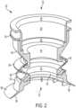
- the internal vacuum passage 32 includes several components, each with potentially different inner dimensions.
- the end-effector 22 includes an attachment portion 34 for attaching to a programmable motion device 10 that includes an angled large inner dimension portion 36 as well as a vertical large inner dimension section 38.
- a collar 40 is attached to the attachment portion 34, and includes inner dimension sections 42, 44.
- a flexible bellows 46 that is formed, for example, of compliant elastomeric material has a varying inner dimension portion 48 forming the bellows, and a vertical inner dimension portion 50.
- a vacuum cup 52 is attached to the bellows, and has a vertical inner dimension portion 54 and an expanding inner dimension that leads to the cup lip 56 which provides the opening at the underside 58 thereof for the end-effector 22.
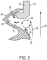
- Figure 3 shows a cut-away portion of one side of the internal vacuum passage 32 (shown in Figure 2 ), showing portions of the bellows 46 and the collar 40.
- a dimension of the vacuum channel may decrease from the contact portion 152 to a flexible intermediate portion 146 as shown at dimension A decreasing to dimension B in Figure 4 .
- the smaller dimension B facilitates creating the high air-flow vacuum at the contact portion 152.
- the flexible intermediate portion 146 e.g., a bellows
- An attachment portion 139 (e.g., an attachment collar and/or attachment unit) with a smallest internal dimension C increases in inner dimension to D as also shown in Figure 4 .
- the flexible intermediate portion 146 is positioned between the smaller dimension B of the contact portion 152, and the smaller dimension C of the attachment portion 139.
- the term flexible intermediate portion may be used interchangeably with the term flexible intermediate section throughout this description.
- a narrow inner dimension vacuum channel is maintained at the contact end of the flexible intermediate portion as shown at B in Figure 4 to provide the high flow vacuum, which widens from dimension A at the contact surface 158 of the contact portion 152 (e.g., vacuum cup).
- the contact portion may additionally provide some flexibility, but the challenge exists in maintaining the high air-flow vacuum through the flexible intermediate portion without attendant high levels of noise.
- the invention provides a bellows insert that extends into the flexible intermediate section a sufficient distance to inhibit a substantial amount of air-flow from entering the bellows portion yet does not significantly inhibit freedom of movement of the flexible intermediate section.
- the bellows insert extends into the flexible intermediate section, disturbing any resonance of moving air within the bellows portion.
- the end-effector attachment portion has a smallest internal dimension of APi d
- the contact end of the flexible intermediate portion has a smallest internal dimension of CEi d
- the values AP id and CE id are within 15% or 10% of each other.
- the end-effector system may produce audible noise when the end-effector attachment portion has a smallest internal dimension of APi d , the bellows insert has a smallest internal dimension of BIi d ; and the values AP id and BI id are within 15% or 10% of each other. For example, if BI id is within 15% of APi d , then bellows inserts in accordance with an aspect of the invention may be used. Surprisingly, the use of designs in accordance with various aspects of the invention reduces the noise generated by a compliant vacuum cup when used in such high air-flow application.
- the invention provides in accordance with certain aspects, an end-effector 122 as well as the use of the end-effector 122 in the system including the programmable motion device 10 of Figure 1 in place of the end-effector 22.
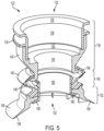
- the end-effector 122 provides a vacuum channel 132 that is provided, in part, by attachment unit 134 having inner dimension portions 136 and 138, collar 146 having inner dimension portions 142 and 144, bellows 146 having varying inner dimension portions 148, and vacuum cup 156.
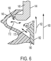
- the end-effector 122 further includes a bellows insert 180 having an inner dimension 182. The presence of the bellows may not significantly inhibit movement (e.g., restrict a change in shape of at least 10%, 20%, 50% or 75%) of the flexible bellows in accordance with various aspects of the invention.
- any movement of air may generally be non-uniform (shown diagrammatically at 172).
- the rate of movement of air within the bellows may be greatly reduced, and large oscillations of air may be reduced or eliminated, resulting in a substantial decrease in unwanted noise during high flow vacuum use with the programmable motion device 10 of Figure 1 where the end-effector 122 is substituted for the end-effector 22.
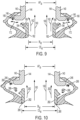
- FIG 9 which shows both sides of the attachment collar 140 (that extends from the attachment unit 134 of Figures 5 , 7 and 8 ) and the flexible intermediate portion 146, including the vacuum cup 152, and the bellows insert 180.
- the inner dimension portion 144 of the collar 140, and the inner dimension portion 150 of the flexible intermediate portion 146 may be aligned or closely aligned.
- the contact end of the flexible intermediate portion 246 may be provided that has a smallest internal dimension (CE id ) that is larger than the internal dimension of the attachment portion (AP id ) such that the smallest internal dimension (BI id ) of the bellows insert is aligned or nearly aligned with the smallest internal dimension of the attachment portion (AP id ) (resulting in a whistle absent a bellows insert in accordance with an aspect of the invention).
- the smallest internal dimension of the attachment portion (AP id ) and the smallest internal dimension (CE id ) of the contact end of the flexible intermediate portion may vary no more than 15% of each other in dimension (e.g., diameter), and preferably may vary no more than 10% of each other in dimension (e.g., diameter).
- the smallest internal dimension of the attachment portion (AP id ) and the smallest internal dimension (BI id ) of the bellows insert may vary no more than 15% of each other in dimension (e.g., diameter), and preferably may vary no more than 10% of each other in dimension (e.g., diameter).
- the invention provides an end-effector 322 and a programmable motion device 10 (of Figure 1 ) including the end-effector 322 (of Figures 11 - 13 ).
- the end-effector 322 provides a vacuum channel 332 that is provided, in part, by an attachment section 339 that includes an attachment unit 334 having inner dimension portions 336 and 338, and a collar 340 having inner dimension portions 342 and 344.
- the end-effector 322 also includes a flexible intermediate section 346 including a bellows having varying inner dimension portions 348, and a contact section 356 including a vacuum cup.
- the end-effector 322 further includes a bellows insert 380 having an inner dimension 382.
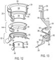
- the bellows insert 380 includes a head portion 384 (optionally to facilitate retention) on a protruding end of the bellows insert that extends into the bellows on a bellow insert extension 386, yet does not negatively affect substantial movement of the flexible intermediate portion 346. Additionally, the bellows insert includes a shoulder engagement feature 388 that is secured against a shoulder 390 of the flexible intermediate section 346 as discussed below with reference to Figures 12 and 13 .
- Figure 12 shows an exploded view of the combined attachment unit 334 and collar 340, the flexible intermediate portion 346 including the vacuum cup 352, and the bellows insert 380.
- the inner dimension portion 344 of the collar 340, and the inner dimension portion 350 of the flexible intermediate portion 346 may be aligned or closely aligned. Applicants have discovered that in such arrangement, under certain conditions of high flow vacuum use, substantial unwanted noise may result absent a bellows insert 380.
- the shoulder engagement feature 388 is secured against the shoulder 390 of the flexible intermediate section 346.
- the shoulder 390 and an outer surface of the bellows insert 380 may additionally serve to secure the vacuum cup 352 to the flexible intermediate portion 346.
Landscapes
- Engineering & Computer Science (AREA)
- Robotics (AREA)
- Mechanical Engineering (AREA)
- Manipulator (AREA)
Claims (15)
- Endeffektor (122, 322) für eine programmierbare Bewegungsvorrichtung (10) zur Verwendung mit einer Unterdruckquelle (26), wobei der Endeffektor Folgendes umfasst:einen Endeffektor-Befestigungsabschnitt (139, 339) zum Befestigen des Endeffektors an der programmierbaren Bewegungsvorrichtung, wobei der Endeffektor-Befestigungsabschnitt einen Unterdruckkanal (132, 332) enthält, der mit der Unterdruckquelle (26) gekoppelt ist;einen Kontaktabschnitt (152, 352) des Endeffektors (122, 322) zum Inkontaktkommen mit einem Objekt, das durch den Kontaktabschnitt (152, 352) des Endeffektors (122, 322) erfasst werden soll;einen flexiblen Zwischenabschnitt (146, 346) mit einem Kontaktende nahe dem Kontaktabschnitt (152, 352) des Endeffektors (122, 322), wobei der flexible Zwischenabschnitt (146, 346) des Endeffektors (122, 322) zwischen dem Endeffektor-Befestigungsabschnitt (139, 339) und dem Kontaktabschnitt (152, 352) des Endeffektors (122, 322) ist, wobei der flexible Zwischenabschnitt (146, 346) einen Balgabschnitt umfasst, der sich radial vom Unterdruckkanal nach außen erstreckt; unddadurch gekennzeichnet, dass er ferner einen Balgeinsatz (180, 380) umfasst, der sich in den flexiblen Zwischenabschnitt (146, 346) erstreckt, um den Luftstrom zu hindern, in den Balgbereich einzutreten, aber dennoch die Bewegungsfreiheit des flexiblen Zwischenabschnitts (146, 346) nicht behindert.
- Endeffektor nach Anspruch 1, wobei der Endeffektor-Befestigungsabschnitt (139, 339) eine kleinste innere Abmessung APid aufweist, das Kontaktende des flexiblen Zwischenabschnitts eine kleinste innere Abmessung CEid aufweist und wobei die Werte APid und CEid innerhalb von 15 % voneinander liegen.
- Endeffektor nach Anspruch 2, wobei die Werte APid und CPid innerhalb von 10 % voneinander liegen.
- Endeffektor nach einem der Ansprüche 1 - 3, wobei der Endeffektor-Befestigungsabschnitt (139, 339) eine kleinste innere Abmessung APid aufweist, der Balgeinsatz (180, 380) eine kleinste innere Abmessung BIid aufweist, und wobei die Werte APid und BIid innerhalb von 15 % voneinander liegen.
- Endeffektor nach Anspruch 4, wobei die Werte APid und BIid innerhalb von 10 % voneinander liegen.
- Endeffektor nach einem der Ansprüche 1-5, wobei der Endeffektor-Befestigungsabschnitt (139, 339) einen Befestigungsabschnitt (134, 334) zwischen einem Befestigungsring (140, 340) und der programmierbaren Bewegungsvorrichtung (10) umfasst.
- Endeffektor nach einem der Ansprüche 1 - 6, wobei der Balgeinsatz (180, 380) einen Kopfabschnitt (384) umfasst, der sich radial nach außen in den Balgabschnitt erstreckt.
- Endeffektor nach Anspruch 7, wobei der Kopfabschnitt (384) des Balgeinsatzes (180, 380) im Allgemeinen ringförmig ist und Ober- und Unterflächen umfasst, die sich radial nach außen zueinander erstrecken und an der radial äußersten Kante des Kopfabschnitts (384) zusammenlaufen.
- Endeffektor nach einem der Ansprüche 1 - 8, wobei der Balgeinsatz (180, 380) ein Schultereingriffsmerkmal umfasst, das gegen eine Schulter des flexiblen Zwischenabschnitts (146, 346) gesichert ist.
- Endeffektor nach einem der Ansprüche 1 - 9, wobei der flexible Zwischenabschnitt (146, 346) aus einem polymeren Material gebildet ist.
- Endeffektor nach einem der Ansprüche 1 - 10, wobei der Kontaktabschnitt (152, 352) aus einem flexiblen polymeren Material gebildet ist.
- Endeffektor nach einem der Ansprüche 1 - 11, wobei sich der Balgeinsatz (180, 380) in den flexiblen Zwischenabschnitt (146, 346) erstreckt, sodass jede Resonanz bewegter Luft innerhalb des Balgabschnitts gestört wird.
- Programmierbare Bewegungsvorrichtung, umfassend einen Endeffektor nach einem der Ansprüche 1 - 12 und eine Unterdruckquelle (26), wobei die Unterdruckquelle (26) am Endeffektor (122, 322) einen Luftdurchsatz von mindestens etwa 2,8 Kubikmetern pro Minute (100 Kubikfuß pro Minute) bereitstellt.
- Programmierbare Bewegungsvorrichtung nach Anspruch 13, wobei die Unterdruckquelle (26) am Endeffektor (122, 322) einen Unterdruck von nicht mehr als etwa 100.000 Pascal unterhalb des atmosphärischen Drucks bereitstellt.
- Programmierbare Bewegungsvorrichtung nach Anspruch 13, wobei die Unterdruckquelle (26) am Endeffektor (122, 322) einen Unterdruck von nicht mehr als etwa 65.000 Pascal unterhalb des atmosphärischen Drucks bereitstellt.
Applications Claiming Priority (2)
| Application Number | Priority Date | Filing Date | Title |
|---|---|---|---|
| US202062970208P | 2020-02-05 | 2020-02-05 | |
| PCT/US2021/016582 WO2021158770A1 (en) | 2020-02-05 | 2021-02-04 | End-effector, programmable motion device and method of operating a programmable motion device |
Publications (2)
| Publication Number | Publication Date |
|---|---|
| EP4100219A1 EP4100219A1 (de) | 2022-12-14 |
| EP4100219B1 true EP4100219B1 (de) | 2025-04-09 |
Family
ID=74860389
Family Applications (1)
| Application Number | Title | Priority Date | Filing Date |
|---|---|---|---|
| EP21710646.7A Active EP4100219B1 (de) | 2020-02-05 | 2021-02-04 | Endeffektor und programmierbare bewegungsvorrichtung |
Country Status (6)
| Country | Link |
|---|---|
| US (2) | US12157223B2 (de) |
| EP (1) | EP4100219B1 (de) |
| CN (1) | CN115052720B (de) |
| CA (1) | CA3170700A1 (de) |
| ES (1) | ES3032869T3 (de) |
| WO (1) | WO2021158770A1 (de) |
Families Citing this family (3)
| Publication number | Priority date | Publication date | Assignee | Title |
|---|---|---|---|---|
| CA3150291A1 (en) | 2019-08-08 | 2021-02-11 | Berkshire Grey, Inc. | Systems and methods for providing, in programmable motion devices, compliant end effectors with noise mitigation |
| EP4100219B1 (de) | 2020-02-05 | 2025-04-09 | Berkshire Grey Operating Company, Inc. | Endeffektor und programmierbare bewegungsvorrichtung |
| NL2031663B1 (en) * | 2022-04-22 | 2023-11-07 | Bollegraaf Patents And Brands B V | Suction head for a waste sorting system |
Family Cites Families (103)
| Publication number | Priority date | Publication date | Assignee | Title |
|---|---|---|---|---|
| US1610363A (en) | 1925-12-22 | 1926-12-14 | Jay J Davis | Lifting and conveying apparatus |
| US2815919A (en) | 1954-10-20 | 1957-12-10 | Pribil Victor | Suction cups |
| US2853333A (en) | 1955-09-07 | 1958-09-23 | Littell Machine Co F J | Vacuum cup |
| US3005652A (en) | 1960-12-14 | 1961-10-24 | Bemis Bro Bag Co | Vacuum gripping device |
| NO120155L (de) | 1961-12-05 | |||
| US3195941A (en) | 1962-08-27 | 1965-07-20 | Whiting Corp | Vacuum gripping pad |
| US3656794A (en) | 1971-01-21 | 1972-04-18 | Diamond Int Corp | Vacuum cup lifter for shell eggs |
| CH526461A (de) | 1971-02-10 | 1972-08-15 | Gis Ag | Unterdruck-Hebevorrichtung |
| US3863969A (en) | 1973-11-01 | 1975-02-04 | Aluminum Co Of America | Vacuum lifter |
| DE2458934A1 (de) * | 1974-12-12 | 1976-06-16 | Lundstroem Goeran | Roboter zum ergreifen, bewegen und abliefern von gegenstaenden |
| FR2495592A1 (fr) | 1980-12-05 | 1982-06-11 | Joulin Sema | Dispositif de prehension fonctionnant par succion |
| FR2527968A1 (fr) | 1982-06-08 | 1983-12-09 | Jaz Ind | Poignet souple sensitif pour organe de manipulation |
| US4557659A (en) | 1982-09-14 | 1985-12-10 | M. Scaglia S.P.A. | Device for supporting and handling loads by means of vacuum operated suction pads |
| DE3324441C2 (de) * | 1983-04-08 | 1986-12-18 | Reinhard Dipl.-Ing. 3070 Nienburg Göpfert | Selbstfahrende Vorrichtung zum Versetzen von Hebegut |
| NO161311C (no) * | 1983-02-24 | 1989-08-02 | Reinhard Goepfert | Selvdrevet innretning for hevning og forflytning av elementer som skal loeftes. |
| US4561687A (en) * | 1984-05-30 | 1985-12-31 | Harris Corporation | Vacuum grip device |
| US4600229A (en) | 1984-08-03 | 1986-07-15 | Oten Peter D | Vacuum cup |
| GB8422338D0 (en) * | 1984-09-04 | 1984-10-10 | Watkiss Automation Ltd | Valve mechanism |
| US4828304A (en) | 1986-09-09 | 1989-05-09 | Kabushiki Kaisha Yakult Honsha | Vacuum adsorption hand |
| DE3810989A1 (de) | 1988-02-01 | 1989-08-10 | Festo Kg | Vorrichtung zur handhabung und insbesondere zum transport von gegenstaenden |
| GB2248435B (en) | 1990-09-06 | 1994-06-22 | Smc Kk | Suction pad |
| DE4116491C1 (de) * | 1991-05-21 | 1992-06-17 | Heidelberger Druckmaschinen Ag, 6900 Heidelberg, De | |
| US5207465A (en) | 1991-10-24 | 1993-05-04 | Rich Donald S | Self-realigning vacuum pickup arrangement |
| WO1995012541A1 (en) | 1993-11-04 | 1995-05-11 | Comalco Aluminium Limited | Vacuum lifting device |
| US5856487A (en) | 1996-02-14 | 1999-01-05 | National Institute Of Immunology | Application of protoberberine alkaloid, berberine, an immunosuppressive agent |
| US5865487A (en) | 1996-05-23 | 1999-02-02 | Motorola, Inc. | Pick-and-place tool for vacuum and magnetic coupling |
| US5890553A (en) | 1996-08-01 | 1999-04-06 | California Institute Of Technology | Multifunction automated crawling system |
| DE19817426B4 (de) | 1998-04-18 | 2004-06-09 | J. Schmalz Gmbh | Greifersystem, insbesondere Vakuumgreifersystem |
| US6131973A (en) | 1998-10-01 | 2000-10-17 | Sikorsky Aircraft Corporation | Vacuum transfer device |
| WO2000023362A1 (en) | 1998-10-20 | 2000-04-27 | Koninklijke Philips Electronics N.V. | Vacuum cup |
| GB9823759D0 (en) | 1998-10-31 | 1998-12-23 | Rota Limited | A safety device |
| DE29905951U1 (de) | 1999-04-06 | 1999-07-29 | J. Schmalz GmbH, 72293 Glatten | Sauggreifer |
| US6193291B1 (en) | 1999-07-20 | 2001-02-27 | Isi Norgren, Inc. | Vacuum cup apparatus |
| KR20020049041A (ko) | 1999-11-09 | 2002-06-24 | 칼 하인쯔 호르닝어 | 흡인에 의하여 전기 부품을 흡착하기 위한 진공 피펫 |
| US6276478B1 (en) | 2000-02-16 | 2001-08-21 | Kathleen Garrubba Hopkins | Adherent robot |
| JP4547649B2 (ja) | 2000-07-31 | 2010-09-22 | Smc株式会社 | 吸着用パッド |
| DE10121344A1 (de) | 2001-05-02 | 2002-11-07 | Fft Flexible Fertigungstechnik | Zum Greifen von Gegenständen ausgebildete Greifvorrichtung |
| US6588718B2 (en) | 2001-06-11 | 2003-07-08 | Syron Engineering & Manufacturing, L.L.C. | Bellowed suction cup |
| DE10140248B4 (de) | 2001-08-09 | 2006-09-28 | J. Schmalz Gmbh | Unterdruckhandhabungseinrichtung |
| TW200505626A (en) | 2003-01-29 | 2005-02-16 | Mitsuboshi Diamond Ind Co Ltd | Vacuum suction head |
| US7017961B1 (en) | 2004-08-06 | 2006-03-28 | Bakery Holdings Llc | Compressive end effector |
| DE102004057775B4 (de) | 2004-11-30 | 2007-05-10 | Multitest Elektronische Systeme Gmbh | Handhabungsvorrichtung zum Zuführen von elektronischen Bauelementen, insbesondere IC's, zu einer Testvorrichtung |
| US7481472B2 (en) | 2005-03-15 | 2009-01-27 | Sage Automation, Inc. | Layer picking end effector system, apparatus and method |
| US7540309B2 (en) | 2005-07-11 | 2009-06-02 | Delaware Capital Formation, Inc. | Auto-release vacuum device |
| DE102005045681B4 (de) | 2005-09-24 | 2007-07-26 | Eckelt Glas Gmbh | Verfahren zum Steuern von Unterdruck-Hebezeugen und Lastsicherungsvorrichtung für Unterdruck-Hebezeuge sowie deren Verwendung |
| US20090142169A1 (en) | 2007-11-30 | 2009-06-04 | Teradyne, Inc. | Vacuum Assisted Manipulation of Objects |
| US20100150743A1 (en) | 2008-12-12 | 2010-06-17 | Norgren Automotive, Inc. | Single Line Venturi Apparatus |
| JP5163541B2 (ja) | 2009-03-02 | 2013-03-13 | 三菱マテリアルテクノ株式会社 | 真空吸着パッド |
| SE532867C2 (sv) | 2009-03-27 | 2010-04-27 | Xerex Ab | Sugkopp med utbytbara tätningsytor |
| KR100932775B1 (ko) | 2009-09-01 | 2009-12-21 | 한국뉴매틱(주) | 진공컵 어셈블리 |
| US20110255948A1 (en) | 2010-04-19 | 2011-10-20 | Malinowski Mark A | Suction Device |
| DE102011115951B4 (de) | 2011-10-13 | 2016-03-31 | BIBA - Bremer Institut für Produktion und Logistik GmbH | Greifwerkzeug zur Förderung von unregelmäßig angeordneten Gütern, Greifersystem mit demselben sowie Verfahren zum Abfördern |
| US8960745B2 (en) | 2011-11-18 | 2015-02-24 | Nike, Inc | Zoned activation manufacturing vacuum tool |
| KR20140001186U (ko) * | 2012-08-16 | 2014-02-27 | (주) 엔텍인더스트리 | 진공 흡착기 |
| EP2708335A1 (de) | 2012-09-14 | 2014-03-19 | Knapp AG | Hochgeschwindigkeits-Greiferwechselsystem |
| US9393686B1 (en) | 2013-03-15 | 2016-07-19 | Industrial Perception, Inc. | Moveable apparatuses having robotic manipulators and conveyors to facilitate object movement |
| WO2014161549A1 (en) | 2013-04-02 | 2014-10-09 | Inva Invest Holding Aps | A flow blocking valve, a vacuum lifting device and a method for operating a vacuum lifting device |
| CN203529438U (zh) | 2013-07-22 | 2014-04-09 | 温州阿尔贝斯气动有限公司 | 一种真空吸盘 |
| CN203680306U (zh) | 2013-12-20 | 2014-07-02 | 君帆工业股份有限公司 | 非接触式多孔真空浮吸器 |
| CN203717601U (zh) | 2014-01-23 | 2014-07-16 | 温州阿尔贝斯气动有限公司 | 一种真空吸盘 |
| FR3020303B1 (fr) | 2014-04-25 | 2016-07-15 | Sileane | Procede et installation de prehension automatique d'un objet. |
| ES2845927T3 (es) | 2014-06-26 | 2021-07-28 | Schmalz J Gmbh | Instalación para la manipulación de piezas de trabajo |
| US10773901B2 (en) | 2014-11-18 | 2020-09-15 | James Laverdiere | Rotary picker with arms |
| FR3032364B1 (fr) | 2015-02-11 | 2017-01-27 | Solystic | Installation pour la separation et l'individualisation d'objets postaux heterogenes avec un systeme de vision a sources laser |
| DE102015202603A1 (de) | 2015-02-12 | 2016-08-18 | J. Schmalz Gmbh | Unterdruckerzeugervorrichtung und Schlauchheber mit einer Unterdruckerzeugervorrichtung |
| KR20160108112A (ko) | 2015-03-05 | 2016-09-19 | 주식회사 씨피씨 | 흡착판 |
| ES2948058T3 (es) | 2015-08-26 | 2023-08-30 | Berkshire Grey Operating Company Inc | Sistemas y métodos para proporcionar conjuntos de válvula de vacío para efectores finales |
| EP4219093B1 (de) | 2015-08-26 | 2025-04-02 | Berkshire Grey Operating Company, Inc. | Systeme und verfahren zur bereitstellung von kontaktdetektion in einem gelenkarm |
| US9911640B2 (en) | 2015-09-01 | 2018-03-06 | Boris Kesil | Universal gripping and suction chuck |
| CA2997280C (en) | 2015-09-01 | 2022-12-13 | Berkshire Grey, Inc. | Systems and methods for providing dynamic robotic control systems |
| ES2960751T3 (es) | 2015-09-08 | 2024-03-06 | Berkshire Grey Operating Company Inc | Sistemas y métodos para proporcionar presión de vacío dinámico en un efector final de brazo articulado |
| EP3349952B1 (de) | 2015-09-15 | 2023-02-01 | Berkshire Grey Operating Company, Inc. | Stülpendeffektor zur verwendung mit einem gelenkarm in einem robotersystem |
| DE102015117315A1 (de) | 2015-10-12 | 2017-04-13 | Wisco Lasertechnik Gmbh | Saugerrahmen |
| ES2929729T3 (es) | 2015-11-13 | 2022-12-01 | Berkshire Grey Operating Company Inc | Sistemas de clasificación para proporcionar clasificación de una variedad de objetos |
| EP4046761B1 (de) | 2016-01-08 | 2025-03-26 | Berkshire Grey Operating Company, Inc. | Systeme und verfahren zur erfassung und bewegung von objekten |
| CA3178174A1 (en) | 2016-02-08 | 2017-08-17 | Berkshire Grey Operating Company, Inc. | Systems and methods for providing processing of a variety of objects employing motion planning |
| CN105668255B (zh) | 2016-03-21 | 2018-06-29 | 南通优元美术图案设计有限公司 | 一种外墙瓷砖码垛装箱装置 |
| WO2018044861A1 (en) | 2016-08-29 | 2018-03-08 | Hershoff Craig L | Contact lens manipulator with suction cup and safety release mechanism |
| US10099867B2 (en) | 2016-11-15 | 2018-10-16 | Amazon Technologies, Inc. | Automated package unloading system |
| EP3544911B1 (de) | 2016-11-28 | 2023-10-18 | Berkshire Grey Operating Company, Inc. | System zur vereinzelung von objekten zur verarbeitung |
| JP6829383B2 (ja) | 2017-02-17 | 2021-02-10 | 三菱電機株式会社 | 把持装置、把持システム及び制御装置 |
| CN115319788A (zh) | 2017-03-06 | 2022-11-11 | 伯克希尔格雷运营股份有限公司 | 用于有效地移动各种物体的系统和方法 |
| WO2018200503A1 (en) | 2017-04-24 | 2018-11-01 | Berkshire Grey, Inc. | Systems and methods for providing singulation of objects for processing using object movement redistribution |
| AT16158U1 (de) * | 2017-08-01 | 2019-02-15 | Dkfm Fritz Kuchler | Saugkopf |
| US10723019B2 (en) | 2017-08-02 | 2020-07-28 | Berkshire Grey, Inc. | Systems and methods for acquiring and moving objects having complex outer surfaces |
| US10668630B2 (en) | 2017-08-22 | 2020-06-02 | Emerging Acquisitions, Llc | High speed manipulation of non-uniform ojects |
| KR102049936B1 (ko) * | 2017-09-11 | 2019-11-28 | 피스코코리아뉴매틱주식회사 | 진공흡착장치 |
| US10814498B2 (en) | 2017-11-07 | 2020-10-27 | Berkshire Grey, Inc. | Systems and methods for providing dynamic vacuum pressure at an end effector using a single vacuum source |
| WO2019143710A1 (en) | 2018-01-17 | 2019-07-25 | Berkshire Grey, Inc. | Systems and methods for efficiently moving a variety of objects |
| JP7024162B2 (ja) * | 2018-02-05 | 2022-02-24 | Smc株式会社 | 真空パッド |
| TWI787529B (zh) | 2018-07-16 | 2022-12-21 | 開曼群島商星猿哲科技國際有限公司 | 用於揀選、分類及放置複數個隨機及新物件之機器人系統 |
| US11865700B2 (en) | 2018-07-27 | 2024-01-09 | Berkshire Grey Operating Company, Inc. | Systems and methods for efficiently exchanging end effector tools |
| JP2022508621A (ja) | 2018-10-03 | 2022-01-19 | ニコラス ペイトン, | ハイブリッドロボットピッキングデバイス |
| US11407589B2 (en) | 2018-10-25 | 2022-08-09 | Berkshire Grey Operating Company, Inc. | Systems and methods for learning to extrapolate optimal object routing and handling parameters |
| JP7289439B2 (ja) | 2018-12-05 | 2023-06-12 | コンバム株式会社 | 吸着パッド |
| CA3123057A1 (en) | 2019-01-31 | 2020-08-06 | RightHand Robotics, Inc. | Gripping device modalities |
| CN113396035A (zh) | 2019-02-27 | 2021-09-14 | 伯克希尔格雷股份有限公司 | 用于在可编程运动系统中的软管布线的系统和方法 |
| EP3959050B1 (de) | 2019-04-25 | 2024-04-17 | Berkshire Grey Operating Company, Inc. | System und verfahren zur aufrechterhaltung der lebensdauer von vakuumschläuchen in schlauchführungssystemen in programmierbaren bewegungssystemen |
| CA3150291A1 (en) | 2019-08-08 | 2021-02-11 | Berkshire Grey, Inc. | Systems and methods for providing, in programmable motion devices, compliant end effectors with noise mitigation |
| US11745360B2 (en) | 2019-10-31 | 2023-09-05 | Intelligrated Headquarters, Llc | Compliant inner lip on a vacuum gripper |
| EP4100219B1 (de) | 2020-02-05 | 2025-04-09 | Berkshire Grey Operating Company, Inc. | Endeffektor und programmierbare bewegungsvorrichtung |
| US12083670B2 (en) | 2020-04-01 | 2024-09-10 | Ambi Robotics, Inc. | End effector device and system for suction-based grasping of bagged objects |
| US20230103821A1 (en) | 2021-10-06 | 2023-04-06 | Dexterity, Inc. | Multi-mode robotic end effector |
-
2021
- 2021-02-04 EP EP21710646.7A patent/EP4100219B1/de active Active
- 2021-02-04 CN CN202180012206.4A patent/CN115052720B/zh active Active
- 2021-02-04 US US17/167,536 patent/US12157223B2/en active Active
- 2021-02-04 CA CA3170700A patent/CA3170700A1/en active Pending
- 2021-02-04 WO PCT/US2021/016582 patent/WO2021158770A1/en not_active Ceased
- 2021-02-04 ES ES21710646T patent/ES3032869T3/es active Active
-
2024
- 2024-10-18 US US18/919,816 patent/US20250144818A1/en active Pending
Also Published As
| Publication number | Publication date |
|---|---|
| US20250144818A1 (en) | 2025-05-08 |
| ES3032869T3 (en) | 2025-07-28 |
| CN115052720B (zh) | 2025-10-21 |
| EP4100219A1 (de) | 2022-12-14 |
| CA3170700A1 (en) | 2021-08-12 |
| CN115052720A (zh) | 2022-09-13 |
| US12157223B2 (en) | 2024-12-03 |
| WO2021158770A1 (en) | 2021-08-12 |
| US20210237285A1 (en) | 2021-08-05 |
Similar Documents
| Publication | Publication Date | Title |
|---|---|---|
| US20250144818A1 (en) | Systems and methods for disrupting resonance in vacuum cup assemblies used with programmable motion devices | |
| EP4010152B1 (de) | Systeme und verfahren zur bereitstellung von nachgiebigen endeffektoren mit geräuschunterdrückung bei programmierbaren bewegungsvorrichtungen | |
| US10850402B2 (en) | Systems and methods for acquiring and moving objects | |
| US7452016B2 (en) | Non-contact carrying device | |
| US5263753A (en) | Gripper for a manipulator | |
| CN110116381A (zh) | 真空吸盘 | |
| JP2019193969A (ja) | 真空動力工具 | |
| US5882055A (en) | Probe for handling microchips | |
| US20040104329A1 (en) | Vibration isolation table | |
| JP7694321B2 (ja) | リフト装置 | |
| CN110382177A (zh) | 用于物体的非接触处理装置 | |
| EP0362907A2 (de) | Saugnapfbefestiger | |
| JP2020189341A (ja) | 吸着搬送装置 | |
| JPH01242345A (ja) | 真空吸着装置 | |
| JP2545552Y2 (ja) | 吸着用パッド | |
| CN210879345U (zh) | 一种真空吸附装置 | |
| JP3243122B2 (ja) | 農産物の吸着保持体 | |
| JP2524579Y2 (ja) | 吸着用パッド | |
| JPH07214489A (ja) | 吸着パッド | |
| JP2021028092A (ja) | 吸着パッドおよびピッキング装置 | |
| JP2512633Y2 (ja) | 吸着装置 | |
| JP2004125080A (ja) | ダブル吸盤具 | |
| JP2003011077A (ja) | 吸着カップ装置 | |
| WO2025126884A1 (ja) | 吸着パッド | |
| JPH0715637U (ja) | 吸引ノズル |
Legal Events
| Date | Code | Title | Description |
|---|---|---|---|
| STAA | Information on the status of an ep patent application or granted ep patent |
Free format text: STATUS: UNKNOWN |
|
| STAA | Information on the status of an ep patent application or granted ep patent |
Free format text: STATUS: THE INTERNATIONAL PUBLICATION HAS BEEN MADE |
|
| PUAI | Public reference made under article 153(3) epc to a published international application that has entered the european phase |
Free format text: ORIGINAL CODE: 0009012 |
|
| STAA | Information on the status of an ep patent application or granted ep patent |
Free format text: STATUS: REQUEST FOR EXAMINATION WAS MADE |
|
| 17P | Request for examination filed |
Effective date: 20220819 |
|
| AK | Designated contracting states |
Kind code of ref document: A1 Designated state(s): AL AT BE BG CH CY CZ DE DK EE ES FI FR GB GR HR HU IE IS IT LI LT LU LV MC MK MT NL NO PL PT RO RS SE SI SK SM TR |
|
| DAV | Request for validation of the european patent (deleted) | ||
| DAX | Request for extension of the european patent (deleted) | ||
| P01 | Opt-out of the competence of the unified patent court (upc) registered |
Effective date: 20230525 |
|
| GRAP | Despatch of communication of intention to grant a patent |
Free format text: ORIGINAL CODE: EPIDOSNIGR1 |
|
| STAA | Information on the status of an ep patent application or granted ep patent |
Free format text: STATUS: GRANT OF PATENT IS INTENDED |
|
| INTG | Intention to grant announced |
Effective date: 20240306 |
|
| GRAJ | Information related to disapproval of communication of intention to grant by the applicant or resumption of examination proceedings by the epo deleted |
Free format text: ORIGINAL CODE: EPIDOSDIGR1 |
|
| STAA | Information on the status of an ep patent application or granted ep patent |
Free format text: STATUS: REQUEST FOR EXAMINATION WAS MADE |
|
| GRAP | Despatch of communication of intention to grant a patent |
Free format text: ORIGINAL CODE: EPIDOSNIGR1 |
|
| STAA | Information on the status of an ep patent application or granted ep patent |
Free format text: STATUS: GRANT OF PATENT IS INTENDED |
|
| INTC | Intention to grant announced (deleted) | ||
| INTG | Intention to grant announced |
Effective date: 20240712 |
|
| GRAJ | Information related to disapproval of communication of intention to grant by the applicant or resumption of examination proceedings by the epo deleted |
Free format text: ORIGINAL CODE: EPIDOSDIGR1 |
|
| STAA | Information on the status of an ep patent application or granted ep patent |
Free format text: STATUS: REQUEST FOR EXAMINATION WAS MADE |
|
| GRAP | Despatch of communication of intention to grant a patent |
Free format text: ORIGINAL CODE: EPIDOSNIGR1 |
|
| STAA | Information on the status of an ep patent application or granted ep patent |
Free format text: STATUS: GRANT OF PATENT IS INTENDED |
|
| INTC | Intention to grant announced (deleted) | ||
| INTG | Intention to grant announced |
Effective date: 20241204 |
|
| GRAS | Grant fee paid |
Free format text: ORIGINAL CODE: EPIDOSNIGR3 |
|
| GRAA | (expected) grant |
Free format text: ORIGINAL CODE: 0009210 |
|
| STAA | Information on the status of an ep patent application or granted ep patent |
Free format text: STATUS: THE PATENT HAS BEEN GRANTED |
|
| AK | Designated contracting states |
Kind code of ref document: B1 Designated state(s): AL AT BE BG CH CY CZ DE DK EE ES FI FR GB GR HR HU IE IS IT LI LT LU LV MC MK MT NL NO PL PT RO RS SE SI SK SM TR |
|
| REG | Reference to a national code |
Ref country code: GB Ref legal event code: FG4D |
|
| REG | Reference to a national code |
Ref country code: CH Ref legal event code: EP |
|
| REG | Reference to a national code |
Ref country code: DE Ref legal event code: R096 Ref document number: 602021028878 Country of ref document: DE |
|
| REG | Reference to a national code |
Ref country code: IE Ref legal event code: FG4D |
|
| REG | Reference to a national code |
Ref country code: NL Ref legal event code: FP |
|
| REG | Reference to a national code |
Ref country code: ES Ref legal event code: FG2A Ref document number: 3032869 Country of ref document: ES Kind code of ref document: T3 Effective date: 20250728 |
|
| REG | Reference to a national code |
Ref country code: AT Ref legal event code: MK05 Ref document number: 1783162 Country of ref document: AT Kind code of ref document: T Effective date: 20250409 |
|
| PG25 | Lapsed in a contracting state [announced via postgrant information from national office to epo] |
Ref country code: PT Free format text: LAPSE BECAUSE OF FAILURE TO SUBMIT A TRANSLATION OF THE DESCRIPTION OR TO PAY THE FEE WITHIN THE PRESCRIBED TIME-LIMIT Effective date: 20250811 Ref country code: FI Free format text: LAPSE BECAUSE OF FAILURE TO SUBMIT A TRANSLATION OF THE DESCRIPTION OR TO PAY THE FEE WITHIN THE PRESCRIBED TIME-LIMIT Effective date: 20250409 |
|
| REG | Reference to a national code |
Ref country code: LT Ref legal event code: MG9D |
|
| PG25 | Lapsed in a contracting state [announced via postgrant information from national office to epo] |
Ref country code: NO Free format text: LAPSE BECAUSE OF FAILURE TO SUBMIT A TRANSLATION OF THE DESCRIPTION OR TO PAY THE FEE WITHIN THE PRESCRIBED TIME-LIMIT Effective date: 20250709 Ref country code: GR Free format text: LAPSE BECAUSE OF FAILURE TO SUBMIT A TRANSLATION OF THE DESCRIPTION OR TO PAY THE FEE WITHIN THE PRESCRIBED TIME-LIMIT Effective date: 20250710 |
|
| PG25 | Lapsed in a contracting state [announced via postgrant information from national office to epo] |
Ref country code: PL Free format text: LAPSE BECAUSE OF FAILURE TO SUBMIT A TRANSLATION OF THE DESCRIPTION OR TO PAY THE FEE WITHIN THE PRESCRIBED TIME-LIMIT Effective date: 20250409 |
|
| PG25 | Lapsed in a contracting state [announced via postgrant information from national office to epo] |
Ref country code: BG Free format text: LAPSE BECAUSE OF FAILURE TO SUBMIT A TRANSLATION OF THE DESCRIPTION OR TO PAY THE FEE WITHIN THE PRESCRIBED TIME-LIMIT Effective date: 20250409 |
|
| PG25 | Lapsed in a contracting state [announced via postgrant information from national office to epo] |
Ref country code: HR Free format text: LAPSE BECAUSE OF FAILURE TO SUBMIT A TRANSLATION OF THE DESCRIPTION OR TO PAY THE FEE WITHIN THE PRESCRIBED TIME-LIMIT Effective date: 20250409 |
|
| PG25 | Lapsed in a contracting state [announced via postgrant information from national office to epo] |
Ref country code: AT Free format text: LAPSE BECAUSE OF FAILURE TO SUBMIT A TRANSLATION OF THE DESCRIPTION OR TO PAY THE FEE WITHIN THE PRESCRIBED TIME-LIMIT Effective date: 20250409 |
|
| PG25 | Lapsed in a contracting state [announced via postgrant information from national office to epo] |
Ref country code: RS Free format text: LAPSE BECAUSE OF FAILURE TO SUBMIT A TRANSLATION OF THE DESCRIPTION OR TO PAY THE FEE WITHIN THE PRESCRIBED TIME-LIMIT Effective date: 20250709 |
|
| PG25 | Lapsed in a contracting state [announced via postgrant information from national office to epo] |
Ref country code: IS Free format text: LAPSE BECAUSE OF FAILURE TO SUBMIT A TRANSLATION OF THE DESCRIPTION OR TO PAY THE FEE WITHIN THE PRESCRIBED TIME-LIMIT Effective date: 20250809 |
|
| PG25 | Lapsed in a contracting state [announced via postgrant information from national office to epo] |
Ref country code: LV Free format text: LAPSE BECAUSE OF FAILURE TO SUBMIT A TRANSLATION OF THE DESCRIPTION OR TO PAY THE FEE WITHIN THE PRESCRIBED TIME-LIMIT Effective date: 20250409 |
|
| REG | Reference to a national code |
Ref country code: DE Ref legal event code: R097 Ref document number: 602021028878 Country of ref document: DE |
|
| PG25 | Lapsed in a contracting state [announced via postgrant information from national office to epo] |
Ref country code: DK Free format text: LAPSE BECAUSE OF FAILURE TO SUBMIT A TRANSLATION OF THE DESCRIPTION OR TO PAY THE FEE WITHIN THE PRESCRIBED TIME-LIMIT Effective date: 20250409 Ref country code: SM Free format text: LAPSE BECAUSE OF FAILURE TO SUBMIT A TRANSLATION OF THE DESCRIPTION OR TO PAY THE FEE WITHIN THE PRESCRIBED TIME-LIMIT Effective date: 20250409 |
|
| PG25 | Lapsed in a contracting state [announced via postgrant information from national office to epo] |
Ref country code: CZ Free format text: LAPSE BECAUSE OF FAILURE TO SUBMIT A TRANSLATION OF THE DESCRIPTION OR TO PAY THE FEE WITHIN THE PRESCRIBED TIME-LIMIT Effective date: 20250409 |
|
| PG25 | Lapsed in a contracting state [announced via postgrant information from national office to epo] |
Ref country code: EE Free format text: LAPSE BECAUSE OF FAILURE TO SUBMIT A TRANSLATION OF THE DESCRIPTION OR TO PAY THE FEE WITHIN THE PRESCRIBED TIME-LIMIT Effective date: 20250409 |
|
| PG25 | Lapsed in a contracting state [announced via postgrant information from national office to epo] |
Ref country code: SK Free format text: LAPSE BECAUSE OF FAILURE TO SUBMIT A TRANSLATION OF THE DESCRIPTION OR TO PAY THE FEE WITHIN THE PRESCRIBED TIME-LIMIT Effective date: 20250409 |
|
| PLBE | No opposition filed within time limit |
Free format text: ORIGINAL CODE: 0009261 |
|
| STAA | Information on the status of an ep patent application or granted ep patent |
Free format text: STATUS: NO OPPOSITION FILED WITHIN TIME LIMIT |
|
| REG | Reference to a national code |
Ref country code: CH Ref legal event code: L10 Free format text: ST27 STATUS EVENT CODE: U-0-0-L10-L00 (AS PROVIDED BY THE NATIONAL OFFICE) Effective date: 20260218 |
|
| PGFP | Annual fee paid to national office [announced via postgrant information from national office to epo] |
Ref country code: NL Payment date: 20260226 Year of fee payment: 6 |
|
| 26N | No opposition filed |
Effective date: 20260112 |
|
| PGFP | Annual fee paid to national office [announced via postgrant information from national office to epo] |
Ref country code: GB Payment date: 20260227 Year of fee payment: 6 |
|
| PGFP | Annual fee paid to national office [announced via postgrant information from national office to epo] |
Ref country code: ES Payment date: 20260302 Year of fee payment: 6 |
|
| PGFP | Annual fee paid to national office [announced via postgrant information from national office to epo] |
Ref country code: DE Payment date: 20260227 Year of fee payment: 6 |
|
| PGFP | Annual fee paid to national office [announced via postgrant information from national office to epo] |
Ref country code: IT Payment date: 20260319 Year of fee payment: 6 |
|
| PGFP | Annual fee paid to national office [announced via postgrant information from national office to epo] |
Ref country code: FR Payment date: 20260225 Year of fee payment: 6 |