EP4098138B1 - Visierverriegelungsmechanismus und helm - Google Patents
Visierverriegelungsmechanismus und helm Download PDFInfo
- Publication number
- EP4098138B1 EP4098138B1 EP20916552.1A EP20916552A EP4098138B1 EP 4098138 B1 EP4098138 B1 EP 4098138B1 EP 20916552 A EP20916552 A EP 20916552A EP 4098138 B1 EP4098138 B1 EP 4098138B1
- Authority
- EP
- European Patent Office
- Prior art keywords
- shield
- attachment
- holding
- detachment
- lock mechanism
- Prior art date
- Legal status (The legal status is an assumption and is not a legal conclusion. Google has not performed a legal analysis and makes no representation as to the accuracy of the status listed.)
- Active
Links
Images



Classifications
-
- A—HUMAN NECESSITIES
- A42—HEADWEAR
- A42B—HATS; HEAD COVERINGS
- A42B3/00—Helmets; Helmet covers ; Other protective head coverings
- A42B3/04—Parts, details or accessories of helmets
- A42B3/18—Face protection devices
- A42B3/22—Visors
- A42B3/221—Attaching visors to helmet shells, e.g. on motorcycle helmets
- A42B3/222—Attaching visors to helmet shells, e.g. on motorcycle helmets in an articulated manner, e.g. hinge devices
- A42B3/223—Attaching visors to helmet shells, e.g. on motorcycle helmets in an articulated manner, e.g. hinge devices with means for locking the visor in a fully open, intermediate or closed position
-
- A—HUMAN NECESSITIES
- A42—HEADWEAR
- A42B—HATS; HEAD COVERINGS
- A42B3/00—Helmets; Helmet covers ; Other protective head coverings
- A42B3/04—Parts, details or accessories of helmets
- A42B3/18—Face protection devices
- A42B3/22—Visors
- A42B3/221—Attaching visors to helmet shells, e.g. on motorcycle helmets
- A42B3/222—Attaching visors to helmet shells, e.g. on motorcycle helmets in an articulated manner, e.g. hinge devices
Definitions
- the present disclosure relates to a shield lock mechanism that is for attachment to a shell and a helmet.
- a known helmet includes an attachment-detachment mechanism that allows a shield to be attached and detached by performing an operation from outside the helmet.
- the attachment-detachment mechanism includes an attachment-detachment member that is moved between a shield holding position and a shield removable position.
- the attachment-detachment member is biased to the shield holding position by a biasing member and moved to the shield removable position when an operation force that counters the biasing force is applied from outside the helmet.
- Japanese Laid-Open Patent Publication No. 2002-339142 discloses an example.
- US 2014/352020 discloses a shield lock mechanism according to the preamble of claim 1.
- inertial force that counters the biasing force acts on the attachment-detachment member may move the attachment-detachment member from the shield holding position to the shield removable position in an unexpected manner.
- An objective of the present disclosure is to provide a shield lock mechanism and a helmet that avoids a situation in which a holding member that holds the shield is moved by an impact.
- a shield lock mechanism in accordance with the present disclosure is for attachment to a shell.
- the shield lock mechanism includes a holding member, a biasing member, and a restriction member.
- the holding member is configured to be moved by an external operation between a holding position at which a shield is held and an attachment-detachment position at which the shield can be attached and detached.
- the biasing member is configured to constantly bias the holding member toward the holding position.
- the restriction member is configured to be moved by an external operation between a restricting position at which movement of the holding member arranged at the holding position is restricted and a canceling position at which the restriction is canceled.
- a helmet in accordance with the present disclosure includes a shell, a shield, and the above-described shield lock mechanism.
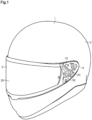
- FIG. 1 to 7 An embodiment of a shield lock mechanism will now be described with reference to Figs. 1 to 7 .
- the front, rear, left, right, up, and down directions with respect to a helmet and the shield lock mechanism correspond to the directions as viewed by a person wearing the helmet.
- a helmet 1 includes a shell 2, a shield 3, and a shield lock mechanism 4.
- a wearer of the helmet 1 wears the shell 2 on the head.
- the shell 2 has a window opening 2H.
- the window opening 2H ensures the field of view of the helmet wearer.
- the shield 3 is light-transmissive. When the window opening 2H is closed with the shield 3, the shield 3 protects the head of the helmet wearer while maintaining the field of view of the helmet wearer.
- the shield 3 is attached to a left side surface of the shell 2 by the shield lock mechanism 4 such that the shield lock mechanism 4 is sandwiched between the shield 3 and the shell 2.
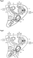
- the shield lock mechanism 4 includes a base plate 10, a holding member 40, a restriction member 50, a first coil spring 60, and a second coil spring 70.
- the second coil spring 70 is an example of a biasing member.
- the base plate 10 includes two bases. Each base is a plate that is curved in correspondence with the left side surface of the shell 2.
- the two bases include a fixed base 20 and a movable base 30.
- the fixed base 20 is fixed on the left side surface of the shell 2.
- the movable base 30 is arranged to cover a left portion of the fixed base 20.
- the movable base 30 is connected to the fixed base 20 in a manner movable in forward and rearward directions.
- the fixed base 20 and the movable base 30 sandwich part of the holding member 40 (refer to Fig. 4 ), part of the restriction member 50 (refer to Fig. 4 ), and part of the second coil spring 70 (refer to Fig. 4 ).
- the first coil spring 60 extends in the front-rear direction and is connected between the fixed base 20 and the movable base 30.
- the first coil spring 60 is in contact with the fixed base 20 and the movable base 30 and constantly biases the movable base 30 toward the rear of the helmet wearer.
- the base plate 10 includes a first engagement hole 31, a second engagement hole 32, and an opening degree determination portion 21.
- the first engagement hole 31 includes a first attachment-detachment hole 31A and a first guide hole 31B.
- the first attachment-detachment hole 31A is a substantially rectangular small hole extending through a portion of the movable base 30 peripheral to the upper end of the movable base 30.
- the first guide hole 31B is an elongated hole extending through a portion of the movable base 30 peripheral to the upper end of the movable base 30.
- the first guide hole 31B extends rearward from the first attachment-detachment hole 31A in an arcuate manner.
- the shield 3 includes a first engagement tab 3A projecting toward the fixed base 20.
- the first engagement tab 3A has a claw-shaped distal end that is bent downward.
- the distal end of the first engagement tab 3A is sized to enter the space between the fixed base 20 and the movable base 30 through the first attachment-detachment hole 31A. Further, the distal end of the first engagement tab 3A is sized to be removable from between the fixed base 20 and the movable base 30 through the first attachment-detachment hole 31A.
- the first engagement tab 3A has a thickness such that the first engagement tab 3A is slidable in the first guide hole 31B along the first guide hole 31B.
- the thickness of the first engagement tab 3A corresponds to the amount of the first engagement tab 3A extending from the shield 3 toward the fixed base 20 such that the first engagement tab 3A is slidable in the first guide hole 31B.
- the first guide hole 31B guides the movement of the first engagement tab 3A in the direction in which the first guide hole 31B extends.
- the first engagement tab 3A is guided by the first guide hole 31B so that the shield 3 is stably opened and closed.
- the second engagement hole 32 includes a second attachment-detachment hole 32A and a second guide hole 32B.
- the second attachment-detachment hole 32A (refer to Fig. 4 ) is a substantially rectangular hole extending through a portion of the movable base 30 peripheral to the upper end of the movable base 30 in front of the first attachment-detachment hole 31A.
- the second attachment-detachment hole 32A is larger than the first attachment-detachment hole 31A.
- the second guide hole 32B is an elongated hole extending through the movable base 30.
- the second guide hole 32B extends in an arcuate manner from the second attachment-detachment hole 32A toward the rear lower end of the movable base 30.
- the shield 3 includes a second engagement tab 3B projecting toward the fixed base 20.
- the second engagement tab 3B has a claw-shaped distal end that is bent upward and rearward.
- the distal end of the second engagement tab 3B is sized to enter the space between the fixed base 20 and the movable base 30 through the second attachment-detachment hole 32A.
- the distal end of the second engagement tab 3B is sized to be removable from between the fixed base 20 and the movable base 30 through the second attachment-detachment hole 32A.
- the second engagement tab 3B has a thickness such that the second engagement tab 3B is slidable in the second guide hole 32B along the second guide hole 32B.
- the thickness of the second engagement tab 3B corresponds to the amount of the second engagement tab 3B extending from the shield 3 toward the fixed base 20 such that the second engagement tab 3B is slidable in the second guide hole 32B.
- the second guide hole 32B guides the movement of the second engagement tab 3B in the direction in which the second guide hole 32B extends.
- the second engagement tab 3B is guided by the second guide hole 32B so that the shield 3 is stably opened and closed.
- the opening degree determination portion 21 is located at a portion of the fixed base 20 that is not covered by the movable base 30.
- the opening degree determination portion 21 includes a multi-serrated engagement portion 21A and an attachment-detachment stepped portion 21B arranged on the fixed base 20.
- the multi-serrated engagement portion 21A extends in an arcuate manner from the front upper end of the fixed base 20 toward the rear lower end of the fixed base 20.
- the multi-serrated engagement portion 21A includes ridges that project toward the front and valleys that are recessed toward the rear, and the ridges and the valleys are alternately arranged along the multi-serrated engagement portion 21A.
- the attachment-detachment stepped portion 21B is an upwardly extending recess that is continuous with the upper end of the multi-serrated engagement portion 21A.
- the shield 3 includes an opening degree adjustment projection 3C projecting toward the fixed base 20.
- the opening degree adjustment projection 3C is sized to move into the valleys of the multi-serrated engagement portion 21A and the recess of the attachment-detachment stepped portion 21B. Further, the opening degree adjustment projection 3C is flexible so that the opening degree adjustment projection 3C moves over the ridges of the multi-serrated engagement portion 21A one at a time when opening or closing the shield 3.
- the opening degree adjustment projection 3C enters one of the valleys of the multi-serrated engagement portion 21A and fixes the opening degree of the shield 3. Further, as shown in Fig. 3 , when the opening degree adjustment projection 3C enters the attachment-detachment stepped portion 21B of the fixed base 20, the shield 3 is in a fully open position.
- the first engagement tab 3A is in the first guide hole 31B and the second engagement tab 3B is in the second guide hole 32B.
- the opening degree adjustment projection 3C is in the lowest valley of the multi-serrated engagement portion 21A. This fixes the shield 3 in the fully closed position.
- the first engagement tab 3A is moved along the first guide hole 31B
- the second engagement tab 3B is moved along the second guide hole 32B
- the opening degree adjustment projection 3C is moved over the ridges of the multi-serrated engagement portion 21A one at a time. This intermittently fixes the opening degree of the shield 3.
- the first engagement tab 3A is in the first attachment-detachment hole 31A and the second engagement tab 3B is in the second attachment-detachment hole 32A. Further, the opening degree adjustment projection 3C is in the attachment-detachment stepped portion 21B. This allows the shield 3 to be removed by performing an external operation on the holding member 40 and the restriction member 50.
- the fixed base 20 includes a first attachment portion 22 and a second attachment portion 23.
- Each of the first attachment portion 22 and the second attachment portion 23 is a projection projecting toward the movable base 30.
- the first attachment portion 22 includes a screw hole 22A
- the second attachment portion 23 includes a screw hole 23A. Screws are inserted through the screw holes 22A and 23A and fastened to the shell 2 to fix the fixed base 20 to the shell 2.
- the first attachment portion 22 includes a spring seat 22W projecting toward the rear (refer to Figs. 2 and 3 ).
- the movable base 30 includes an attachment-detachment operation hole 33, a lock lever hole 34, a shaft support hole 35, and a movable hole 36. Further, the movable base 30 includes a spring seat 33W that is formed in front of the attachment-detachment operation hole 33 and a spring seat 36W that is formed at the rear of the movable hole 36.
- the first attachment portion 22 is inserted through the movable hole 36.
- the first coil spring 60 is supported by the spring seat 22W of the fixed base 20, which is located at the rear of the first attachment portion 22, and the spring seat 36W of the movable base 30, which is located at the rear of the movable hole 36.
- the first coil spring 60 constantly biases the movable base 30 toward the rear relative to the fixed base 20.
- the movable base 30 receives an operation force that counters the biasing force of the first coil spring 60, the movable base 30 is moved toward the front together with the shield 3.
- the opening degree adjustment projection 3C of the shield 3 alternately contacts the ridges and the valleys of the multi-serrated engagement portion 21A.
- the movable base 30 receives an external force that counters the biasing force of the first coil spring 60. This moves the movable base 30 forward.
- the helmet wearer applies an operation force that counters the biasing force of the first coil spring 60 to the shield 3 and moves the movable base 30. This moves the opening degree adjustment projection 3C from one valley onto an adjacent ridge and moves the shield 3.
- the opening degree adjustment projection 3C stays in contact with the valley and fixes the opening degree of the shield 3.
- the holding member 40 includes a shield holding tab 41, an attachment-detachment lever 42, and a connecting plate 43.
- the attachment-detachment lever 42 is an example of an operating portion.
- the shield holding tab 41 is defined by an upper end of the holding member 40 and is plate-shaped.
- the shield holding tab 41 is sized to be pivotal in forward and rearward directions in the second attachment-detachment hole 32A.
- the attachment-detachment lever 42 is looped and defined by a lower end of the holding member 40.
- the attachment-detachment lever 42 is sized to be pivotal in forward and rearward directions in the attachment-detachment operation hole 33, which extends through the movable base 30.
- the lower end of the attachment-detachment operation hole 33 is defined by a pivot guide surface 33E that is curved and extends in the front-rear direction.
- the pivot guide surface 33E contacts the lower end wall of the attachment-detachment lever 42 to guide pivoting of the attachment-detachment lever 42.
- the connecting plate 43 is a plate-shaped portion that connects the shield holding tab 41 and the attachment-detachment lever 42 in the up-down direction.
- the connecting plate 43 is accommodated between the fixed base 20 and the movable base 30.
- a groove is formed in the surface of the movable base 30 facing the fixed base 20, and the groove extends in the up-down direction to accommodate the connecting plate 43.
- the connecting plate 43 is guided by the side surfaces of the groove in the movable base 30 to allow pivoting of the shield holding tab 41 and the holding member 40.
- the shield holding tab 41 is arranged at the front end of its movable range. Accordingly, when an external operation force is not acting on the holding member 40, the attachment-detachment lever 42 is arranged at the rear end and the shield holding tab 41 is arranged at the front end. Thus, the holding member 40 is in a holding position.
- the attachment-detachment lever 42 is arranged at the front end of its movable range and the shield holding tab 41 is arranged at the rear end of its movable range.
- the holding member 40 is in an attachment-detachment position.
- the holding member 40 is in the attachment-detachment position.
- the direction in which the holding member 40 is moved from the holding position corresponds to the direction in which the shield holding tab 41 is moved, and the direction includes a main component in the front-rear direction.
- the movable base 30 includes a plate-shaped shield sandwiching tab 32C that extends from the front end of the second attachment-detachment hole 32A toward the inner side of the second attachment-detachment hole 32A. If the shield holding tab 41 is arranged at the front end of its movable range when the second engagement tab 3B of the shield 3 is located inside the second attachment-detachment hole 32A, the second engagement tab 3B of the shield 3 will be sandwiched between the shield sandwiching tab 32C and the shield holding tab 41 so that the second engagement tab 3B of the shield 3 cannot be removed from the second attachment-detachment hole 32A. In this case, the shield 3 is continuously held by the shield lock mechanism 4.
- the shield holding tab 41 is arranged at the rear end of its movable range when the second engagement tab 3B of the shield 3 is located inside the second attachment-detachment hole 32A, the second engagement tab 3B of the shield 3 can be removed from the second attachment-detachment hole 32A.
- the second coil spring 70 is supported by the spring seat 33W of the movable base 30, which projects toward the attachment-detachment operation hole 33, and a spring seat 42W that is arranged on the attachment-detachment lever 42 and projects toward the front.
- the second coil spring 70 constantly biases the attachment-detachment lever 42 toward the rear end of the movable range of the attachment-detachment lever 42.
- the attachment-detachment lever 42 receives an operation force that counters the biasing force of the second coil spring 70, the attachment-detachment lever 42 is moved toward the front end of its movable range and the shield holding tab 41 is moved toward the rear end of its movable range.
- the restriction member 50 includes a lock lever 51, a restriction projection 52, and a shaft portion 53.
- the shaft portion 53 is an example of a shaft support portion.
- the shaft portion 53 has the form of a disc, and the lock lever 51 and the restriction projection 52 are connected to the circumferential surface of the shaft portion 53.
- the shaft portion 53 is rotatably supported by the movable base 30 in the shaft support hole 35.
- the shaft portion 53 is rotated by an external operation that rotates the lock lever 51, and the shaft portion 53 rotates the restriction projection 52 in the same direction as the rotational direction of the lock lever 51.
- the lock lever 51 is a lever extending from the shaft portion 53 toward the front.
- the lock lever 51 is sized to be pivotal in the lock lever hole 34 of the movable base 30.
- the lock lever 51 is pivoted between a canceling operation position and a restricting operation position. In the canceling operation position, the distal end of the lock lever 51 is at the uppermost position of its movable range. In the restricting operation position, the distal end of the lock lever 51 is at the lowermost position of its movable range.
- the restriction projection 52 is a projection extending from the shaft portion 53 toward the rear.
- the restriction projection 52 is sized to be pivotal between the fixed base 20 and the movable base 30.
- the restriction projection 52 is pivoted between a restricting actuation position and a canceling actuation position. In the restricting actuation position, the distal end of the restriction projection 52 contacts the attachment-detachment lever 42 arranged at the rear end of it movable range. In the canceling actuation position, the distal end of the restriction projection 52 does not contact the attachment-detachment lever 42 arranged at the rear end of its movable range.
- the restriction projection 52 is in the restricting actuation position and the restriction member 50 is in the restricting position.
- the restriction member 50 in the restricting position fixes the attachment-detachment lever 42 at the rear end of its movable range to restrict movement of the holding member 40 from the holding position.
- the restriction projection 52 is in the canceling actuation position and the restriction member 50 is in the canceling position.
- the restriction member 50 in the canceling position permits movement of the attachment-detachment lever 42 from the rear end of its movable range. This allows the holding member 40 to be moved by an external operation from the holding position to the attachment-detachment position.
- the direction in which the restriction member 50 is moved from the restricting position corresponds to the direction in which the restriction projection 52 is moved and the rotational direction about the shaft portion 53.
- the direction includes a main component in the up-down direction.
- an operation force is applied to the lock lever 51 to move the restriction member 50 between the restricting operation position (solid line) and the canceling operation position (double-dashed line).
- the restriction projection 52 contacts the attachment-detachment lever 42 and restricts movement of the holding member 40 from the holding position to the attachment-detachment position.
- the holding member 40 will resist and not be moved by the inertial force acting on the holding member 40.
- the direction in which the holding member 40 is moved from the holding position differs from the direction in which the restriction member 50 is moved from the restricting position.
- the direction in which the holding member 40 is moved from the holding position to the attachment-detachment position differs from the direction in which the restriction member 50 is moved from the restricting position to the canceling position. This will limit the inertial force that acts on and moves both of the holding member 40 and the restriction member 50. Therefore, even when an external impact is applied to the helmet 1, the shield 3 will be continuously held by the shield lock mechanism 4.
- the restriction projection 52 is separated from the attachment-detachment lever 42 to permit the movement of the holding member 40 from the holding position to the attachment-detachment position.
- the restriction member 50 is arranged in the canceling actuation position when the shield 3 is in the fully open position
- the first engagement tab 3A will be arranged in the first attachment-detachment hole 31A and the second engagement tab 3B will be arranged in the second attachment-detachment hole 32A.
- the attachment-detachment lever 42 receives an operation force that counters the biasing force of the second coil spring 70
- the holding member 40 is moved from the holding position to the attachment-detachment position. This allows the shield 3 to be removed from the shield lock mechanism 4.
- the restriction member 50 When attaching the shield 3 to the shell 2, first, the restriction member 50 is arranged in the canceling actuation position. Then, an operation force that counters the biasing force of the second coil spring 70 is applied to the attachment-detachment lever 42 to move the holding member 40 from the holding position to the attachment-detachment position. In this state, the first engagement tab 3A is inserted through the first attachment-detachment hole 31A, the second engagement tab 3B is inserted through the second attachment-detachment hole 32A, and then the opening degree adjustment projection 3C is arranged in the attachment-detachment stepped portion 21B. This attaches the shield 3 to the shield lock mechanism 4.
- first coil spring 60 and the second coil spring 70 are configured to apply biasing force to the movable base 30 or the holding member 40, respectively.
- first coil spring 60 and the second coil spring 70 may each be a biasing member such as a leaf spring or a disc spring.
- the shield lock mechanism 4 is not limited to a structure in which the second coil spring 70 and the restriction member 50 both contact the attachment-detachment lever 42.
- the shield lock mechanism 4 may be configured so that the second coil spring 70 and the restriction member 50 apply an acting force to different portions of the holding member 40. For example, advantages (1) to (5) will be obtained even when the second coil spring 70 contacts the attachment-detachment lever 42 and the restriction member 50 contacts the shield holding tab 41.
- the holding member 40 only has to be movable between the holding position and the attachment-detachment position when an external operation force is applied.
- the holding member 40 may be supported by a rotational shaft and rotated by an external operation force.
- the holding member 40 may be a push-down switch, an on-off switch, or a screw switch.
Landscapes
- Helmets And Other Head Coverings (AREA)
Claims (8)
- Visierverriegelungsmechanismus (4) zur Befestigung an einer Schale (2), wobei der Visierverriegelungsmechanismus (4) aufweist:ein Halteelement (40), das dazu vorgesehen ist, durch externe Betätigung zwischen einer Halteposition, in der ein Visier (3) gehalten wird, und einer Befestigungs-/Löseposition, in der das Visier (3) befestigt und gelöst werden kann, bewegt zu werden;ein Vorspannelement (70), das dazu vorgesehen ist, das Halteelement (40) konstant in Richtung der Halteposition vorzuspannen; und gekennzeichnet durchein Beschränkungselement (50), das dazu vorgesehen ist, durch externe Betätigung zwischen einer Beschränkungsposition, in der eine Bewegung des in der Halteposition angeordneten Halteelements (40) in die Befestigungs-/Löseposition beschränkt ist, und einer Aufhebungsposition, in der die Beschränkung aufgehoben ist, bewegt zu werden.
- Visierverriegelungsmechanismus (4) nach Anspruch 1, wobei
eine Richtung, in der das Halteelement (40) aus der Halteposition bewegt wird, verschieden ist von einer Richtung, in der das Beschränkungselement (50) aus der Beschränkungsposition bewegt wird. - Visierverriegelungsmechanismus (4) nach Anspruch 2, wobeidie Richtung, in der das Halteelement (40) aus der Halteposition bewegt wird, eine Hauptkomponente in Vor-Zurück-Richtung umfasst, unddie Richtung, in der das Beschränkungselement (50) aus der Beschränkungsposition bewegt wird, eine Hauptkomponente in Auf-Ab-Richtung umfasst.
- Visierverriegelungsmechanismus (4) nach einem der Ansprüche 1 bis 3, ferner aufweisend:eine Basisplatte (10), die zwei Basisteile (20, 30) umfasst, wobeidas Halteelement (40) zumindest teilweise sandwichartig zwischen den zwei Basisteilen (20, 30) angeordnet ist und von der Basisplatte (10) gelagert ist unddie Basisplatte (10) eine gekrümmte Fläche (33E) umfasst, die dazu vorgesehen ist, ein Schwenken des Halteelements (40) zwischen der Halteposition und der Befestigungs-/Löseposition zu führen.
- Visierverriegelungsmechanismus (4) nach einem der Ansprüche 1 bis 3, weiter aufweisend:eine Basisplatte (10), die zwei Basisteile (20, 30) umfasst, wobeidas Beschränkungselement (50) zumindest teilweise sandwichartig zwischen den zwei Basisteilen (20, 30) angeordnet ist und von der Basisplatte (10) gelagert ist unddie Basisplatte (10) ein Wellenlagerloch (35) umfasst, das dazu vorgesehen ist, eine Rotation des Beschränkungselements (50) zwischen der Beschränkungsposition und der Aufhebungsposition zu führen.
- Visierverriegelungsmechanismus (4) nach einem der Ansprüche 1 bis 3, ferner aufweisend:eine Basisplatte (10), die zwei Basisteile (20, 30) umfasst, wobei das Halteelement (40) zumindest teilweise sandwichartig zwischen den zwei Basisteilen (20, 30) angeordnet ist und von der Basisplatte (10) gelagert ist, unddas Beschränkungselement (50) zumindest teilweise sandwichartig zwischen den zwei Basisteilen (20, 30) angeordnet ist und von der Basisplatte (10) gelagert ist unddie Basisplatte (10) eine gekrümmte Oberfläche (33E) aufweist, die dazu vorgesehen ist, ein Schwenken des Halteelements (40) zwischen der Halteposition und der Befestigungs-/Löseposition zu führen, und ein Wellenlagerloch (35) aufweist, das dazu vorgesehen ist, eine Rotation des Beschränkungselements (50) zwischen der Beschränkungsposition und der Aufhebungsposition zu führen.
- Visierverriegelungsmechanismus (4) nach einem der Ansprüche 1 bis 6, wobei das Halteelement (40) einen Betätigungsbereich (42) aufweist, der dazu vorgesehen ist, eine externe Betätigung aufzunehmen,das Vorspannelement (70) dazu vorgesehen ist, den Betätigungsbereich (42) konstant zu kontaktieren und den Betätigungsbereich (42) mit einer Vorspannkraft zu beaufschlagen, unddas Beschränkungselement (50) dazu vorgesehen ist, den Betätigungsbereich (42) in der Beschränkungsposition zu kontaktieren, um eine Bewegung des Betätigungsbereichs (42) zu beschränken, und dazu vorgesehen ist, in der Aufhebungsposition von dem Betätigungsbereich (42) getrennt zu werden, um eine Bewegung des Betätigungsbereichs (42) zu möglich zu machen.
- Helm, aufweisend:eine Schale (2),ein Visier (30) undden Visierverriegelungsmechanismus (4) nach einem der Ansprüche 1 bis 7.
Applications Claiming Priority (2)
| Application Number | Priority Date | Filing Date | Title |
|---|---|---|---|
| JP2020012269A JP6917487B2 (ja) | 2020-01-29 | 2020-01-29 | シールドロック機構、およびヘルメット |
| PCT/JP2020/038180 WO2021152921A1 (ja) | 2020-01-29 | 2020-10-08 | シールドロック機構、およびヘルメット |
Publications (3)
| Publication Number | Publication Date |
|---|---|
| EP4098138A1 EP4098138A1 (de) | 2022-12-07 |
| EP4098138A4 EP4098138A4 (de) | 2024-01-31 |
| EP4098138B1 true EP4098138B1 (de) | 2025-05-14 |
Family
ID=77078495
Family Applications (1)
| Application Number | Title | Priority Date | Filing Date |
|---|---|---|---|
| EP20916552.1A Active EP4098138B1 (de) | 2020-01-29 | 2020-10-08 | Visierverriegelungsmechanismus und helm |
Country Status (5)
| Country | Link |
|---|---|
| US (1) | US12029271B2 (de) |
| EP (1) | EP4098138B1 (de) |
| JP (1) | JP6917487B2 (de) |
| CN (1) | CN114845594B (de) |
| WO (1) | WO2021152921A1 (de) |
Families Citing this family (4)
| Publication number | Priority date | Publication date | Assignee | Title |
|---|---|---|---|---|
| KR102466845B1 (ko) * | 2021-03-04 | 2022-11-16 | (주)에이치제이씨 | 헬멧용 회동수단 |
| KR102445325B1 (ko) * | 2021-04-07 | 2022-09-23 | (주)에이치제이씨 | 쉴드 회동제어수단 |
| JP7532436B2 (ja) | 2022-03-07 | 2024-08-13 | 株式会社Shoei | ヘルメット |
| CN221843962U (zh) * | 2024-02-28 | 2024-10-18 | 上海和汇安全用品有限公司 | 镜片锁止机构以及护目镜 |
Family Cites Families (9)
| Publication number | Priority date | Publication date | Assignee | Title |
|---|---|---|---|---|
| JP3385610B2 (ja) * | 1998-08-31 | 2003-03-10 | 株式会社ホンダアクセス | ヘルメットのシールド取付構造 |
| JP4656756B2 (ja) | 2001-05-18 | 2011-03-23 | 株式会社Shoei | ヘルメットのシールド板制御装置 |
| US8069499B2 (en) * | 2006-05-15 | 2011-12-06 | Shoei Co., Ltd. | Helmet shield attaching mechanism, and helmet attached with the same |
| JP4215797B2 (ja) | 2006-12-14 | 2009-01-28 | 株式会社アライヘルメット | ヘルメットにおけるシールドのロック機構 |
| US7895678B2 (en) * | 2007-08-06 | 2011-03-01 | Bell Sports, Inc. | Helmet with improved shield mount and precision shield control |
| CN202907882U (zh) * | 2012-11-14 | 2013-05-01 | 台州远景体育用品有限公司 | 一种头盔的外镜片操纵机构 |
| JP6148538B2 (ja) * | 2013-06-03 | 2017-06-14 | 株式会社Shoei | ヘルメットのシールド取付け機構 |
| JP5807093B1 (ja) * | 2014-06-27 | 2015-11-10 | 株式会社アライヘルメット | ヘルメット |
| CN207666075U (zh) * | 2017-12-21 | 2018-07-31 | 浙江远景体育用品有限公司 | 一种摩托车用揭面头盔 |
-
2020
- 2020-01-29 JP JP2020012269A patent/JP6917487B2/ja active Active
- 2020-10-08 EP EP20916552.1A patent/EP4098138B1/de active Active
- 2020-10-08 CN CN202080089923.2A patent/CN114845594B/zh active Active
- 2020-10-08 WO PCT/JP2020/038180 patent/WO2021152921A1/ja not_active Ceased
- 2020-10-08 US US17/781,590 patent/US12029271B2/en active Active
Also Published As
| Publication number | Publication date |
|---|---|
| US12029271B2 (en) | 2024-07-09 |
| EP4098138A4 (de) | 2024-01-31 |
| EP4098138A1 (de) | 2022-12-07 |
| US20220408868A1 (en) | 2022-12-29 |
| JP6917487B2 (ja) | 2021-08-11 |
| WO2021152921A1 (ja) | 2021-08-05 |
| JP2021116502A (ja) | 2021-08-10 |
| CN114845594B (zh) | 2026-01-23 |
| CN114845594A (zh) | 2022-08-02 |
Similar Documents
| Publication | Publication Date | Title |
|---|---|---|
| US12029271B2 (en) | Shield lock mechanism and helmet | |
| EP1856999B1 (de) | Mechanismus zur Montage eines Helmvisiers und damit versehener Helm | |
| JP4084231B2 (ja) | 自動車のインサイドドアハンドル装置 | |
| EP0471127A1 (de) | Vorrichtung zum Befestigen einer Visierscheibe an einem Helm | |
| WO2012029445A1 (ja) | グローブボックス装置 | |
| EP3170415B1 (de) | Helm | |
| JP6025385B2 (ja) | 把手装置 | |
| JP2017218731A (ja) | 車両用ドア固定装置の可動楔装置 | |
| JP4714168B2 (ja) | ドアハンドル装置 | |
| WO2019016900A1 (ja) | スライドファスナーのスライダー | |
| JPH04309681A (ja) | スライド蝶番 | |
| US9791822B2 (en) | Image forming apparatus having an opening-closing member and a lock mechanism | |
| JP2001098817A (ja) | グローブボックス用リッドロック装置 | |
| JP5422241B2 (ja) | 車両のドア操作ハンドル | |
| JP7118418B2 (ja) | レンズフード | |
| JP4646653B2 (ja) | ボックス用リッドの取付構造 | |
| KR100248235B1 (ko) | 캠코더의 렌즈 커버 개폐장치 | |
| JP4932445B2 (ja) | 扉の取付構造 | |
| JP2002333199A (ja) | 風向調整装置 | |
| JP4067628B2 (ja) | 電気錠のスライドカバー | |
| JP7008563B2 (ja) | 機能部品の取付構造 | |
| JP2001032591A (ja) | グローブボックス用リッドロック装置 | |
| JP4143159B2 (ja) | カメラ用手動レンズバリア | |
| JP2002219934A (ja) | ドアトリムの位置決め構造 | |
| JP4262491B2 (ja) | グローブボックス装置 |
Legal Events
| Date | Code | Title | Description |
|---|---|---|---|
| STAA | Information on the status of an ep patent application or granted ep patent |
Free format text: STATUS: THE INTERNATIONAL PUBLICATION HAS BEEN MADE |
|
| PUAI | Public reference made under article 153(3) epc to a published international application that has entered the european phase |
Free format text: ORIGINAL CODE: 0009012 |
|
| STAA | Information on the status of an ep patent application or granted ep patent |
Free format text: STATUS: REQUEST FOR EXAMINATION WAS MADE |
|
| 17P | Request for examination filed |
Effective date: 20220802 |
|
| AK | Designated contracting states |
Kind code of ref document: A1 Designated state(s): AL AT BE BG CH CY CZ DE DK EE ES FI FR GB GR HR HU IE IS IT LI LT LU LV MC MK MT NL NO PL PT RO RS SE SI SK SM TR |
|
| DAV | Request for validation of the european patent (deleted) | ||
| DAX | Request for extension of the european patent (deleted) | ||
| A4 | Supplementary search report drawn up and despatched |
Effective date: 20240105 |
|
| RIC1 | Information provided on ipc code assigned before grant |
Ipc: A42B 3/22 20060101AFI20231222BHEP |
|
| GRAP | Despatch of communication of intention to grant a patent |
Free format text: ORIGINAL CODE: EPIDOSNIGR1 |
|
| STAA | Information on the status of an ep patent application or granted ep patent |
Free format text: STATUS: GRANT OF PATENT IS INTENDED |
|
| INTG | Intention to grant announced |
Effective date: 20241205 |
|
| P01 | Opt-out of the competence of the unified patent court (upc) registered |
Free format text: CASE NUMBER: APP_564/2025 Effective date: 20250107 |
|
| GRAS | Grant fee paid |
Free format text: ORIGINAL CODE: EPIDOSNIGR3 |
|
| GRAA | (expected) grant |
Free format text: ORIGINAL CODE: 0009210 |
|
| STAA | Information on the status of an ep patent application or granted ep patent |
Free format text: STATUS: THE PATENT HAS BEEN GRANTED |
|
| AK | Designated contracting states |
Kind code of ref document: B1 Designated state(s): AL AT BE BG CH CY CZ DE DK EE ES FI FR GB GR HR HU IE IS IT LI LT LU LV MC MK MT NL NO PL PT RO RS SE SI SK SM TR |
|
| REG | Reference to a national code |
Ref country code: GB Ref legal event code: FG4D |
|
| REG | Reference to a national code |
Ref country code: CH Ref legal event code: EP |
|
| REG | Reference to a national code |
Ref country code: DE Ref legal event code: R096 Ref document number: 602020051437 Country of ref document: DE |
|
| REG | Reference to a national code |
Ref country code: IE Ref legal event code: FG4D |
|
| REG | Reference to a national code |
Ref country code: NL Ref legal event code: MP Effective date: 20250514 |
|
| PG25 | Lapsed in a contracting state [announced via postgrant information from national office to epo] |
Ref country code: PT Free format text: LAPSE BECAUSE OF FAILURE TO SUBMIT A TRANSLATION OF THE DESCRIPTION OR TO PAY THE FEE WITHIN THE PRESCRIBED TIME-LIMIT Effective date: 20250915 Ref country code: FI Free format text: LAPSE BECAUSE OF FAILURE TO SUBMIT A TRANSLATION OF THE DESCRIPTION OR TO PAY THE FEE WITHIN THE PRESCRIBED TIME-LIMIT Effective date: 20250514 Ref country code: ES Free format text: LAPSE BECAUSE OF FAILURE TO SUBMIT A TRANSLATION OF THE DESCRIPTION OR TO PAY THE FEE WITHIN THE PRESCRIBED TIME-LIMIT Effective date: 20250514 |
|
| REG | Reference to a national code |
Ref country code: LT Ref legal event code: MG9D |
|
| PG25 | Lapsed in a contracting state [announced via postgrant information from national office to epo] |
Ref country code: GR Free format text: LAPSE BECAUSE OF FAILURE TO SUBMIT A TRANSLATION OF THE DESCRIPTION OR TO PAY THE FEE WITHIN THE PRESCRIBED TIME-LIMIT Effective date: 20250815 Ref country code: NO Free format text: LAPSE BECAUSE OF FAILURE TO SUBMIT A TRANSLATION OF THE DESCRIPTION OR TO PAY THE FEE WITHIN THE PRESCRIBED TIME-LIMIT Effective date: 20250814 |
|
| PG25 | Lapsed in a contracting state [announced via postgrant information from national office to epo] |
Ref country code: NL Free format text: LAPSE BECAUSE OF FAILURE TO SUBMIT A TRANSLATION OF THE DESCRIPTION OR TO PAY THE FEE WITHIN THE PRESCRIBED TIME-LIMIT Effective date: 20250514 Ref country code: PL Free format text: LAPSE BECAUSE OF FAILURE TO SUBMIT A TRANSLATION OF THE DESCRIPTION OR TO PAY THE FEE WITHIN THE PRESCRIBED TIME-LIMIT Effective date: 20250514 |
|
| REG | Reference to a national code |
Ref country code: AT Ref legal event code: MK05 Ref document number: 1794030 Country of ref document: AT Kind code of ref document: T Effective date: 20250514 |
|
| PG25 | Lapsed in a contracting state [announced via postgrant information from national office to epo] |
Ref country code: BG Free format text: LAPSE BECAUSE OF FAILURE TO SUBMIT A TRANSLATION OF THE DESCRIPTION OR TO PAY THE FEE WITHIN THE PRESCRIBED TIME-LIMIT Effective date: 20250514 |
|
| PG25 | Lapsed in a contracting state [announced via postgrant information from national office to epo] |
Ref country code: HR Free format text: LAPSE BECAUSE OF FAILURE TO SUBMIT A TRANSLATION OF THE DESCRIPTION OR TO PAY THE FEE WITHIN THE PRESCRIBED TIME-LIMIT Effective date: 20250514 |
|
| PG25 | Lapsed in a contracting state [announced via postgrant information from national office to epo] |
Ref country code: AT Free format text: LAPSE BECAUSE OF FAILURE TO SUBMIT A TRANSLATION OF THE DESCRIPTION OR TO PAY THE FEE WITHIN THE PRESCRIBED TIME-LIMIT Effective date: 20250514 |
|
| PG25 | Lapsed in a contracting state [announced via postgrant information from national office to epo] |
Ref country code: RS Free format text: LAPSE BECAUSE OF FAILURE TO SUBMIT A TRANSLATION OF THE DESCRIPTION OR TO PAY THE FEE WITHIN THE PRESCRIBED TIME-LIMIT Effective date: 20250814 |
|
| PG25 | Lapsed in a contracting state [announced via postgrant information from national office to epo] |
Ref country code: IS Free format text: LAPSE BECAUSE OF FAILURE TO SUBMIT A TRANSLATION OF THE DESCRIPTION OR TO PAY THE FEE WITHIN THE PRESCRIBED TIME-LIMIT Effective date: 20250914 |
|
| PG25 | Lapsed in a contracting state [announced via postgrant information from national office to epo] |
Ref country code: LV Free format text: LAPSE BECAUSE OF FAILURE TO SUBMIT A TRANSLATION OF THE DESCRIPTION OR TO PAY THE FEE WITHIN THE PRESCRIBED TIME-LIMIT Effective date: 20250514 |
|
| PGFP | Annual fee paid to national office [announced via postgrant information from national office to epo] |
Ref country code: DE Payment date: 20251020 Year of fee payment: 6 |
|
| PGFP | Annual fee paid to national office [announced via postgrant information from national office to epo] |
Ref country code: GB Payment date: 20251024 Year of fee payment: 6 |
|
| PG25 | Lapsed in a contracting state [announced via postgrant information from national office to epo] |
Ref country code: SM Free format text: LAPSE BECAUSE OF FAILURE TO SUBMIT A TRANSLATION OF THE DESCRIPTION OR TO PAY THE FEE WITHIN THE PRESCRIBED TIME-LIMIT Effective date: 20250514 Ref country code: DK Free format text: LAPSE BECAUSE OF FAILURE TO SUBMIT A TRANSLATION OF THE DESCRIPTION OR TO PAY THE FEE WITHIN THE PRESCRIBED TIME-LIMIT Effective date: 20250514 |
|
| PGFP | Annual fee paid to national office [announced via postgrant information from national office to epo] |
Ref country code: IT Payment date: 20251031 Year of fee payment: 6 |
|
| PGFP | Annual fee paid to national office [announced via postgrant information from national office to epo] |
Ref country code: FR Payment date: 20251029 Year of fee payment: 6 |
|
| PG25 | Lapsed in a contracting state [announced via postgrant information from national office to epo] |
Ref country code: CZ Free format text: LAPSE BECAUSE OF FAILURE TO SUBMIT A TRANSLATION OF THE DESCRIPTION OR TO PAY THE FEE WITHIN THE PRESCRIBED TIME-LIMIT Effective date: 20250514 |
|
| PG25 | Lapsed in a contracting state [announced via postgrant information from national office to epo] |
Ref country code: EE Free format text: LAPSE BECAUSE OF FAILURE TO SUBMIT A TRANSLATION OF THE DESCRIPTION OR TO PAY THE FEE WITHIN THE PRESCRIBED TIME-LIMIT Effective date: 20250514 |
|
| PG25 | Lapsed in a contracting state [announced via postgrant information from national office to epo] |
Ref country code: SK Free format text: LAPSE BECAUSE OF FAILURE TO SUBMIT A TRANSLATION OF THE DESCRIPTION OR TO PAY THE FEE WITHIN THE PRESCRIBED TIME-LIMIT Effective date: 20250514 |
|
| PG25 | Lapsed in a contracting state [announced via postgrant information from national office to epo] |
Ref country code: RO Free format text: LAPSE BECAUSE OF FAILURE TO SUBMIT A TRANSLATION OF THE DESCRIPTION OR TO PAY THE FEE WITHIN THE PRESCRIBED TIME-LIMIT Effective date: 20250514 |
|
| REG | Reference to a national code |
Ref country code: DE Ref legal event code: R097 Ref document number: 602020051437 Country of ref document: DE |
|
| PLBE | No opposition filed within time limit |
Free format text: ORIGINAL CODE: 0009261 |
|
| STAA | Information on the status of an ep patent application or granted ep patent |
Free format text: STATUS: NO OPPOSITION FILED WITHIN TIME LIMIT |
|
| REG | Reference to a national code |
Ref country code: CH Ref legal event code: L10 Free format text: ST27 STATUS EVENT CODE: U-0-0-L10-L00 (AS PROVIDED BY THE NATIONAL OFFICE) Effective date: 20260325 |
|
| 26N | No opposition filed |
Effective date: 20260217 |