EP4093302B1 - Umkehrerfassungsvorrichtungen mit materialdepots - Google Patents
Umkehrerfassungsvorrichtungen mit materialdepots Download PDFInfo
- Publication number
- EP4093302B1 EP4093302B1 EP20708315.5A EP20708315A EP4093302B1 EP 4093302 B1 EP4093302 B1 EP 4093302B1 EP 20708315 A EP20708315 A EP 20708315A EP 4093302 B1 EP4093302 B1 EP 4093302B1
- Authority
- EP
- European Patent Office
- Prior art keywords
- depot
- flexible tube
- support catheter
- inversion support
- tube
- Prior art date
- Legal status (The legal status is an assumption and is not a legal conclusion. Google has not performed a legal analysis and makes no representation as to the accuracy of the status listed.)
- Active
Links
Images


Classifications
-
- A—HUMAN NECESSITIES
- A61—MEDICAL OR VETERINARY SCIENCE; HYGIENE
- A61B—DIAGNOSIS; SURGERY; IDENTIFICATION
- A61B17/00—Surgical instruments, devices or methods
- A61B17/22—Implements for squeezing-off ulcers or the like on inner organs of the body; Implements for scraping-out cavities of body organs, e.g. bones; for invasive removal or destruction of calculus using mechanical vibrations; for removing obstructions in blood vessels, not otherwise provided for
- A61B17/22031—Gripping instruments, e.g. forceps, for removing or smashing calculi
-
- A—HUMAN NECESSITIES
- A61—MEDICAL OR VETERINARY SCIENCE; HYGIENE
- A61B—DIAGNOSIS; SURGERY; IDENTIFICATION
- A61B17/00—Surgical instruments, devices or methods
- A61B17/22—Implements for squeezing-off ulcers or the like on inner organs of the body; Implements for scraping-out cavities of body organs, e.g. bones; for invasive removal or destruction of calculus using mechanical vibrations; for removing obstructions in blood vessels, not otherwise provided for
- A61B17/221—Gripping devices in the form of loops or baskets for gripping calculi or similar types of obstructions
-
- A—HUMAN NECESSITIES
- A61—MEDICAL OR VETERINARY SCIENCE; HYGIENE
- A61B—DIAGNOSIS; SURGERY; IDENTIFICATION
- A61B17/00—Surgical instruments, devices or methods
- A61B17/00234—Surgical instruments, devices or methods for minimally invasive surgery
- A61B2017/00292—Surgical instruments, devices or methods for minimally invasive surgery mounted on or guided by flexible, e.g. catheter-like, means
-
- A—HUMAN NECESSITIES
- A61—MEDICAL OR VETERINARY SCIENCE; HYGIENE
- A61B—DIAGNOSIS; SURGERY; IDENTIFICATION
- A61B17/00—Surgical instruments, devices or methods
- A61B17/22—Implements for squeezing-off ulcers or the like on inner organs of the body; Implements for scraping-out cavities of body organs, e.g. bones; for invasive removal or destruction of calculus using mechanical vibrations; for removing obstructions in blood vessels, not otherwise provided for
- A61B17/221—Gripping devices in the form of loops or baskets for gripping calculi or similar types of obstructions
- A61B2017/2215—Gripping devices in the form of loops or baskets for gripping calculi or similar types of obstructions having an open distal end
-
- A—HUMAN NECESSITIES
- A61—MEDICAL OR VETERINARY SCIENCE; HYGIENE
- A61B—DIAGNOSIS; SURGERY; IDENTIFICATION
- A61B2217/00—General characteristics of surgical instruments
- A61B2217/002—Auxiliary appliance
- A61B2217/007—Auxiliary appliance with irrigation system
Definitions
- the apparatuses and methods described herein relate to mechanical removal of material from within a body lumen.
- described herein are mechanical inverting tube apparatuses having a depot configured to hold the flexible tube in a quick-release configuration.
- Mechanical inverting tube apparatuses may be particularly advantageous.
- thrombectomy devices and particularly for mechanical thrombectomy devices that can be easily and accurately delivered through the, often tortious, anatomy in the peripheral and central vasculature, then be reliably deployed to remove clot material.
- mechanical inverting tube apparatuses that are easy to operate and that are capable of removing large volumes of material from a body lumen (e.g., a blood vessel) using an inverting tube without requiring reloading of the inverting tube.
- Described herein are apparatuses and methods that may address these needs.
- the present invention is directed to an apparatus for removing a material from a body lumen as defined in claim 1. Embodiments of the invention are recited in the dependent claims.
- Described herein are apparatuses and methods using and making such apparatuses for removing material from a body lumen and methods of using them.
- these apparatuses e.g., devices, systems, etc.
- methods of using and making them may be used to remove large amounts of material from the body lumen.
- the apparatuses typically operate by inverting a flexible tube, e.g., a knitted, woven, braided, solid, or laser-cut tube, over a distal end opening of a catheter so that the flexible tube rolls into the catheter and draws material from the body lumen with it into the catheter.
- inverting tube apparatuses may operate continuously within a body until the entire length of flexible tube has been drawn into the catheter, after which point the apparatus must be withdrawn and removed.
- the apparatuses and methods described herein are adapted to include a depot for holding, in a compressed configuration, a long length of the flexible tube.
- the depot is preferably configured to facilitate the release of the flexible tube with a low release force, and in a manner that prevents snagging or binding of the flexible tube on the body of the catheter or when rolling and inverting into the catheter.
- the inverting tube apparatuses described herein are particularly useful for removing clots (e.g., thrombi) from blood vessels.
- these apparatuses may be referred to as inverting mechanical thrombectomy apparatuses and/or inverting tube thrombectomy apparatuses. These apparatuses may be deployed to efficiently ingest one or more large clots, without requiring reloading or replacement.
- the apparatuses described herein may be configured to provide a high pulling efficiency (e.g., low resistance) to ingest and remove clots including relatively long clots (e.g., greater than 10 mm length, greater than 15 cm, greater than 20 cm, greater than 25 cm, greater than 30 cm, greater than 35 cm, etc.).
- relatively long clots e.g., greater than 10 mm length, greater than 15 cm, greater than 20 cm, greater than 25 cm, greater than 30 cm, greater than 35 cm, etc.
- the apparatuses described herein may be configured to store long lengths of flexible tube at a proximal end of the apparatus, thereby enabling removal of large volumes of clot in a single pass.
- the apparatuses described herein may include one or more features that allow even longer flexible tubes, such as flexible tubes that are longer than the length of the catheter (e.g., the inversion support catheter) over which the flexible tube is being inverted, to be withdrawn easily, without jamming or binding on the catheter.
- flexible tubes such as flexible tubes that are longer than the length of the catheter (e.g., the inversion support catheter) over which the flexible tube is being inverted, to be withdrawn easily, without jamming or binding on the catheter.
- the apparatuses described herein for removing material from a body lumen include an elongate inversion support catheter having a proximal end region, a distal end region, and a distal end opening, and a flexible tube having a distal first end that may be pulled proximally through the catheter, and a depot on the proximal end region of the support catheter holding some of the flexible tube in a compressed configuration.
- the flexible tube may extend over an outer surface of the inversion support catheter be configured to invert into the distal end opening of the inversion support catheter when pulled proximally through the inversion support catheter.
- the depot on the proximal end region of the inversion support catheter include an inner storage region configured such that a proximal portion of the flexible tube may be held in a compressed configuration within the inner storage region, wherein the proximal portion of the flexible tube is configured to unfurl out of a distal end opening of the depot when the flexible tube pulled proximally into the inversion support catheter.
- an apparatus for removing material from a body lumen includes: an elongate inversion support catheter having a proximal end region, a distal end region, and a distal end opening; an elongate puller extending within the inversion support catheter; a flexible tube having a distal first end attached to the puller, wherein the flexible tube extends over an outer surface of the inversion support catheter and is configured to invert into the distal end opening of the inversion support catheter when the puller is pulled proximally; a depot on the proximal end region of the inversion support catheter, the depot comprising an inner storage region, wherein a proximal portion of the flexible tube is held compressed within the inner storage region in a folded pattern (e.g., scrunched up along the elongate length, forming a zig-zag pattern) and is configured to unfurl out of a distal end opening of the depot when the puller is pulled proximally; and a distal guide forming the distal
- any of the apparatuses described herein may optionally include a puller disposed within the inversion support catheter to which the first end of the flexible tube is connected, e.g., at or near the distal end region of the puller.
- the puller may (at least initially) reside within the inversion support catheter, and may be pulled proximally to invert and roll the flexible tube into the inversion support catheter.
- the flexible tube may be sufficiently long such that, even after the puller is completely withdrawn from the lumen of the inversion support catheter, the medical practitioner performing the clot removal procedure may continue to pull on the flexible tube to remove additional material from the body lumen.
- the flexible tube may be formed of any material, and particularly knitted, woven, braided or slotted materials, including knitted, woven and/or braided materials formed of a fiber (e.g., metallic, polymeric, etc., such as Nitinol, stainless steel, etc.).
- the flexible tube may be shape-set.
- the flexible tube may be formed to a shape having an inner diameter (ID) in the un-inverted configuration (e.g., that rides over the outside surface of the inversion support catheter) that is slightly larger than the outer diameter (OD) of the catheter.
- ID inner diameter
- OD outer diameter
- these apparatuses may be delivered into the body within an intermediate catheter (sometime referred to herein as a delivery catheter).
- the flexible tube may have a maximum outer diameter in the un-inverted configuration that is the same or slightly smaller than the inner diameter of the intermediate catheter. Configuring the outer diameter of the flexible tube to be between the ID of the intermediate catheter and the OD of the inversion support catheter may reduce the pull force needed to withdraw the flexible tube into the inversion support catheter. This may be particularly useful for inversion support catheters that are longer than, for example, about 15 cm (e.g., about 40 cm or longer, about 50 cm or longer, about 60 com or longer, about 90 cm or longer, etc.).
- the flexible tube may be compressed within the depot in a folded, zig-zag (e.g., "scrunched" up) configuration, so that the diameter may vary, allowing five-fold or greater (e.g., ten-fold or more, 15 fold or more, 20 fold or more, 25 fold or more, etc.) compression within the depot.
- zig-zag e.g., "scrunched" up
- an apparatus for removing a material from a body lumen includes: an elongate inversion support catheter having a proximal end region, a distal end region, and a distal end opening; an elongate puller extending within the inversion support catheter; a flexible tube having a distal first end attached to the puller, wherein the flexible tube extends over an outer surface of the inversion support catheter and is configured to invert into the distal end opening of the inversion support catheter when the puller is pulled proximally; and a depot on the proximal end region of the inversion support catheter, the depot comprising an inner storage region, wherein a proximal portion of the flexible tube is held compressed within the inner storage region in a folded, e.g., fan-folded and/or zig-zag pattern, and is configured to unfurl out of a distal end opening of the depot when the puller is pulled proximally.
- any of these apparatuses may further include a distal guide forming the distal end opening of the depot, wherein the distal guide is configured to guide the flexible tube out of the depot as the flexible tube is unfurled.
- the distal guide may present a lubricious surface (e.g., including a liner and/or coated by and/or formed of a material that is itself lubricious such as PTFE, PE, etc.
- the distal guide may comprise a lubricious material.
- the distal guide may be configured to form an annular channel out of which the compressed flexible tube may leave the inner storage region of the depot.
- the distal guide is configured to engage with an introducer sheath to secure the depot to the introducer sheath.
- Coupling the depot e.g., the distal guide portion of the depot
- the depot may advantageously stabilize the depot (and therefore the flexible tube) as the device is advanced and/or actuated.
- the depot and in particular the distal guide portion of the depot when included, may be configured to engage over a proximal sheath hub of the introducer sheath.
- the depot is instead configured to engage within a proximal sheath hub of the introducer sheath.
- the distal guide portion of the depot may extend nearly completely or partially along the length of the inversion support catheter.
- the distal guide may extend greater than 40% (e.g., greater than 45%, greater than 50%, greater than 55%, greater than 60%, greater than 65%, greater than 70%, greater than 75%, greater than 80%, etc.) of the length of the inversion support catheter.
- the distal guide may extend distally over the outer surface of the inversion support catheter for greater than 5 cm (e.g., greater than 10 cm, greater than 15 cm, greater than 20 cm, greater than 25 cm, greater than 30 cm, greater than 35 cm, greater than 40 cm, greater than 45 cm, etc.).
- the depot is configured so that the user may be able to see into the inner storage region of the depot.
- the depot may comprise a transparent outer region allowing visualization of the flexible tube within the inner storage region.
- the depot includes a window or port for viewing the inner storage region.
- the flexible tube may be compressed within the inner storage region into a folded configuration (e.g., fanfold and/or zig-zag pattern), in which the flexible tube forms alternating right and left turns.
- the folded configuration is approximate, in that the turns (e.g., folds) may be non-uniformly arranged and may be irregular in size and shape.
- the folding is a scrunching along the length of the tube (e.g., over a mandrel and/or the inversion support catheter). The fold may be referred to as a fanfold, with repeated folds along the tube length.
- the bends forming the folds may be 'soft' (e.g., curves) rather than sharp (e.g., angular) or a combination of both.
- the fanfold pattern may also be referred to herein as a zig-zag pattern. Examples of this scrunched-up pattern are provided herein, in which the flexible tube may stack up along the longitudinal length, compressing the flexible tube. In some variations the folded flexible tube may form regions of larger and smaller outer diameter (OD).
- the OD may be approximately the same, but the flexible tube maybe compressed in a pattern, such as a helical pattern, around the portion of the inversion support catheter within the depot (e.g., within the inner storage region of the depot).
- the folded (e.g., zig-zag pattern) of the flexible tube is arranged approximately in parallel to a long axis of the inversion support catheter.
- the folded (e.g., zig-zag) pattern of the flexible tube may be arranged approximately transverse to a long axis of the inversion support catheter.
- the flexible tube may be shape-set into the compressed (e.g., zig-zag pattern, the "scrunched" pattern, etc.).
- the flexible tube is instead shape set into the un-compressed (e.g., elongated) form.
- the apparatuses described herein may be configured to store a majority (i.e., greater than 50%) of the flexible tube in a compressed, primed to release configuration within the depot. For example, in some variations greater than 50% of the length of the flexible tube (e.g., greater than 55%, greater than 60%, greater than 65%, greater than 70%, greater than 75%, etc.) is held within the depot in an undeployed configuration.
- a majority i.e., greater than 50%
- greater than 50% of the length of the flexible tube e.g., greater than 55%, greater than 60%, greater than 65%, greater than 70%, greater than 75%, etc.
- the flexible tube may be held compressed within the inner storage region with three fold or greater (e.g., 5 fold or greater, 7 fold or greater, 10 fold or greater, 12 fold or greater, 15 fold or greater, 17 fold or greater, 20 fold or greater, etc.) compression along the length of the flexible tube.
- Any of the apparatuses described herein may further include an introducer sheath; wherein the depot may be configured to engage with the introducer sheath, as described above.
- the depot may include one or more valves configured to receive a flushing solution and/or a pressurizing solution.
- the depots may be configured to reduce the friction between the flexible tube and the depot and/or the inversion support catheter.
- the depot may include an inner liner between the inner storage region and the inversion support catheter.
- the inner store region is lubricious.
- the depot is slideably arranged on the inversion support catheter.
- the depot may be lockable to either or both the inversion support catheter (e.g., at a proximal end of the depot) and/or an introducer sheath.
- the depot may be locked to the introducer sheath to secure it in position.
- a proximal end of the depot may be configured to lock onto the proximal end region of the inversion support catheter.
- the flexible tube may be one of: a knit tube, a woven tube, a braided tube, a solid tube, or a laser-slotted tube.
- a method of removing a clot from a blood vessel may include: advancing an inverting tube apparatus through the blood vessel until a distal end portion of the inverting tube apparatus is located proximate to the clot, wherein the inverting tube apparatus comprises an inversion support catheter having an elongate and flexible catheter body, a puller within a lumen of the inversion support catheter, and a flexible tube coupled at a distal end to the puller, the flexible tube extending over an exterior surface of the inversion support catheter, wherein the flexible tube is held compressed within an inner storage region of a depot on a proximal end region of the inversion support catheter; pulling the puller proximally to thereby roll the flexible tube over a distal end opening of the inversion support catheter so that the flexible tube captures the clot and pull
- Pulling the puller proximally to draw the flexible tube from out of the depot may include guiding the flexible tube out of the inner storage region using a distal guide on the depot. Any of these methods may also include inserting the inverting tube apparatus into an introducer sheath and into the blood vessel.
- the method of operation of the apparatus may include locking the depot to a proximal end of the introducer sheath.
- the method may further include applying a pressure or force within the depot that may assist in expelling the flexible tube from the compressed configuration within the depot.
- the method may further include pressurizing the inner storage region of the depot.
- the method may further include injecting a lubricious material into the depot.
- the method may further include injecting a contrast agent into the depot (in some variations the contrast agent may be pressurized and/or may be lubricious). Any of these materials may be injected through a flushing or pressurizing port. Any of these methods may further include flushing a flushing fluid through the depot.
- mechanical inverting tube apparatuses e.g., systems and devices, including thrombectomy systems and thrombectomy devices
- methods of using them for removing material such as thrombus (e.g., clot) material from a body lumen, such as a blood vessel.
- thrombus e.g., clot
- mechanical inverting tube apparatuses that include a depot configured to hold the flexible tube in a quick-release configuration. These apparatuses may be used to remove a larger amount of material, such as clot material, from a body lumen using an inverting flexible tube that may be many times longer than the length of the apparatus (e.g., the inversion support catheter) without jamming.
- the methods and apparatuses described herein represent a substantial improvement over previously described apparatuses that were either limited to a relatively small maximum length of flexible tube that could be used to invert and withdraw material, or were prone to jamming and failure within the body.
- a mechanical inverting tube apparatus may be configured to remove clot using a length of inverting tube, as shown in FIGS. 1A-1C .
- the apparatuses and methods of using them described herein may effective for use with the vasculature, including the neurovasculature and the peripheral vasculature, including for use with relatively larger and/or longer clots (e.g., relative to the length of the flexible tube).
- FIG. 1A illustrates an example of an inverting tractor mechanical thrombectomy apparatus 100, such as described in U.S. patent application no. 15/496,570 , and in U.S. patent no. 9,463,035 .
- the apparatus includes an inversion support catheter 107 and a flexible tube 103 that extends over the outer surface of the inversion catheter.
- the flexible tube may be referred to as a tractor tube (or flexible tractor tube), and may be attached at one end region to a puller 101, which may be pull wire or pull tube (e.g., catheter), e.g., at the distal end region of the puller.
- the flexible tube may be attached proximal to the distal end of the puller (e.g.
- the puller proximally inverts the flexible tube over the distal end opening 111 of the inversion support catheter to capture and remove a material (such as a clot) in the vessel lumen, as shown in FIGS. 1B and 1C .
- a material such as a clot
- the amount of the material that may be captured corresponds to the length of the flexible tube.
- the inverting tractor mechanical thrombectomy apparatus 100 is shown deployed near a clot 109.
- the puller 101 (shown here as a puller micro catheter, alternatively the puller may be a wire) is held within an elongate inversion support catheter 107 so that the flexile tractor tube 103 extends from the end of the puller 101 and expands toward the inner radius of the elongate inversion support catheter 107; at the distal end opening 111 of the elongate inversion support catheter the tractor tube inverts over itself and extends proximally in an inverted configuration over the distal end of the elongate inversion support catheter.
- the puller 101 shown here as a puller micro catheter, alternatively the puller may be a wire
- the flexile tractor tube 103 extends from the end of the puller 101 and expands toward the inner radius of the elongate inversion support catheter 107
- the tractor tube inverts over itself and extends proximally in an inverted configuration over the distal end
- the elongate inversion support catheter is an elongate tube having a distal end that has the same size inner diameter as the proximal length of the inversion support catheter.
- the distal end of the inversion support catheter may be funnel-shaped (or configured to expand into a funnel shape, see, e.g. FIGS. 4A-4B ).
- the inversion support catheter 107 is shown positioned between the tractor tube (e.g., flexible tube 103) and the puller 101 so that the flexible tube can be pulled proximally by pulling on the puller and rolling the flexible tube into the elongate inversion support catheter so that it inverts.
- the portion of the flexible tube that is inverted over the distal end of the elongate inversion support catheter has an outer diameter that is greater than the outer diameter of the elongate inversion support catheter.
- the flexible tube may be biased so that it has a relaxed expanded configuration with a diameter that is greater than the outer diameter (OD) of the elongate inversion support catheter; in addition, the flexible tube may also be configured (e.g., by heat setting, etc.) so that when the flexible tube is everted and rolled over the distal end opening into the elongate inversion support catheter, the outer diameter of the flexible tube within the elongate inversion support catheter has an outer diameter that is about y times (y fold) the inner diameter of the elongate inversion support catheter (e.g., where y is greater than 0.1x, 0.5x, 0.6x, 0.7x, 0.75x, 0.8x, 0.9x, 1x, etc.
- the inner diameter, ID, of the elongate inversion support catheter This combination of an un-inverted diameter of the flexible tube of greater than the diameter of the OD of the elongate inversion support catheter and an inverted diameter of the flexible tube of greater than, e.g., 0.7x the ID of the elongate inversion support catheter is surprisingly helpful for preventing jamming of the apparatus, both when deploying the apparatus and when rolling the flexible tube over the distal end opening of the elongate inversion support catheter to grab a clot.
- the flexible tube may be expandable and may be coupled to the puller as shown.
- the flexible tube and the puller may comprise the same material but the flexible tube may be more flexible and/or expandable, or may be connected to elongate puller (e.g., a push/pull wire or catheter).
- the puller may be optional (e.g., the flexible tube may itself be pulled proximally into the inversion support catheter).
- the clot may be drawn into the elongate inversion support catheter by pulling the flexible tube proximally into the distal end of the elongate inversion support catheter, as indicated by the arrows 113, 113' showing pulling of the inner portion of the flexible tube, resulting in rolling the flexible tube over the end opening of the catheter and into the catheter distal end and inverting the expandable distal end region so that it is pulled into the catheter, shown by arrows.
- the end of the flexible tube outside of the catheter may be loose relative to the outer wall of the catheter.
- FIGS. 2A-2C illustrate an example of an apparatus 200 including a flexible tube that extends down the majority of the length of the inversion support catheter.
- the flexible inversion support catheter 202 and flexible tube 206 are assembled with the flexible tube attached at the distal end region of the puller 204.
- the apparatus may be long (e.g., 50 cm or greater, 75 cm or greater, 90 cm or greater, 100 cm or greater, 110 cm or greater, 120 cm or greater, 150 cm or greater, etc.).
- FIGS. 2A-2C show the proximal ends of the inversion support catheter 202, which may include a hub region 212.
- the puller 204 is slideable within the inversion support catheter and may also include a hub 214.
- FIG. 2B also illustrates one example of a sheath 208 and the use of the sheath to insert the device through the skin 211 into the patient's body lumen (e.g., vessel).
- the sheath (introducer sheath 208) is shown straight, but may be curved, and includes a proximal sheath hub 210.
- the sheath includes a lumen extending along the length. In some variations the sheath may include a valve.
- FIG. 2C the apparatus is shown deployed (similar to FIG. 1C ), with the puller retracted/retracting proximally 212 to draw the flexible tube 206 over the distal end opening of the inversion support catheter 202 and into the lumen of the inversion support catheter.
- This rolling and inverting movement 216 of the flexible tube may draw a material (such as a clot) into the lumen of the inversion support catheter along with the flexible tube.
- the length of the flexible tube is somewhat limited by the length of the inversion support catheter.
- the flexible tube may be stretched or pulled somewhat along its length (thereby providing a slightly longer length when inside the inversion support catheter, this may be limited; the flexible tube may be configured (e.g., shape set or otherwise) to prevent it from locking down onto the outer surface of the inversion support catheter, which may otherwise increase the pull force required to drawn the flexible tube into the inversion support catheter, and therefore potentially jam or lock onto the inversion support catheter.
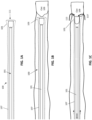
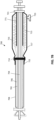
- FIGS. 3A-3C illustrate an example of an apparatus similar to that shown in FIGS. 2A-2C , including a depot 316 for holding a compressed proximal region of the flexible tube 315.
- the depot may be configured to facilitate the release of the compressed flexible tube with a low release force, and in a manner that prevents snagging or binding of the flexible tube either on the body of the catheter or when rolling and inverting into the catheter.
- FIG. 3A shows the apparatus 300 including an inversion support catheter 302, and a flexible tube 306.
- the flexible tube is connected to a puller 304 (optional) that may be used to draw the flexible tube over the distal end opening 309 of the inversion support catheter, as seen in FIGS. 1A-2C .
- the device is illustrated in a linear form, it may be curved.
- the examples provided herein are not shown to scale, unless otherwise indicated, although the relative relationship between the difference components may accurately reflect the interaction of the various components.
- the inversion support catheter may also include a hub 312; the puller may also include a puller hub 314.
- the flexible tube 306 is held in a compressed form ("scrunched") so that a longitudinal section through the flexible tube forms a folded (e.g., zig-zag or fanfold pattern) in which the flexible tube is linearly compressed along the outside of the inversion support catheter, or over an inner wall of the depot (not shown).
- a folded e.g., zig-zag or fanfold pattern
- the proximal end of the flexible tube within the depot is compressed into a folded (e.g., zig-zag or fanfold) pattern in which the flexible tube scrunched perpendicular to the inversion support catheter; e.g., the path taken by the flexible tube curves perpendicularly away and towards the long axis of the inversion support axis.
- these ridges of compressed flexible tube may be separated from adjacent ridges within the inner storage region 317 of the depot 316.
- the inner storage region 317 may include channels or projections configured to separate the compressed flexible tube and to prevent it from internally snagging or catching within the depot.
- the flexible tube within the depot may be arranged for both packing of the flexible tube within the depot as well as to prevent snagging or locking up within the depot or leaving the depot.
- the depot may be lubricious (e.g., may include a lubricious coating, liner, etc.) and/or may be formed of a lubricous material.
- the inner storage region of the depot may be lubricous.
- the flexible tube may be coated with or contain a lubricous material to assist it in sliding within the apparatus.
- the depot which may be referred to herein as a proximal depot or a proximal tube depot, may be formed, at least in part, of a flexible, rigid, or semi-rigid material.
- the depot is configured to be rigid over at least a portion of its length, so as to prevent a user from touching the compressed flexible tube within the depot, which may result in disruption of the flexible tube and jamming of the device.
- the depot may include ridges or struts to support the shape of the depot, even when held by the user, without collapsing or interfering with the compressed flexible tube therein.
- the proximal end of the depot may be configured as a depot hub 321.
- the depot hub may be configured to engage (e.g., releasably engage) with the inversion support catheter, e.g., the hub 312 of the inversion support catheter.
- the depot may be configured to slide along the outside of the inversion support catheter.
- the distal end of the depot may include a distal guide 322 forming the distal end opening of the depot.
- the distal guide may be configured to guide the flexible tube out of the depot as the flexible tube is unfurled.
- the distal guide may be an annular opening into the depot that may provide an outer surface that is curved towards the outer surface of the inversion support catheter.
- the distal guide is rigid or semi-rigid and centers and supports itself over the inversion support catheter to steer the compressed flexible tube out of the depot distally.
- the inner surface of the distal guide may be configured to be lubricious, to enhance release of the flexible tube.
- the depot may generally be configured to engage with a sheath.
- the distal guide may be configured to engage with the sheath (e.g., the sheath hub 310) in a manner that prevents snagging of the flexible tube as it leaves the inner storage region of the depot.
- the distal guide may be configured to engage with the introducer sheath to secure the depot to the introducer sheath.
- the depot e.g., the distal guide of the depot
- the depot may be configured to engage over a proximal sheath hub of the introducer sheath (as will be described in FIG.
- FIG. 3C shows the distal guide 322 of the depot engaging with the sheath hub 310.
- the outer surface of the distal guide fits into the sheath hub.
- the outer surface of the distal guide region may be configured to mate (e.g., releasably mate) with the sheath hub.
- the distal guide is configured to fit into the sheath hub with a friction fit.
- the outer surface of the distal guide is configured to lock onto the sheath hub.
- the attachment between the distal guide and the sheath may be configured to prevent a reduction in the diameter of the distal guide.
- the sheath may be configured so that the distal guide is configured to open to all the flexible tube to be released from the depot after engaging with the sheath. This may prevent premature release of the compressed proximal end of the flexible tube from out of the depot.
- one or more stays may be removed by the engagement between the distal guide and the sheath.
- the distal guide may be opened further once engage with the sheath, e.g., sheath hub (e.g., when engaging over and/or into the sheath hub).
- the apparatus of FIG. 3A is shown being inserted into the body through a sheath 308 having a sheath hub 310 at the proximal end.
- the apparatus may be inserted distally 311 into the body through the sheath 308.
- the inversion support catheter and pusher may be locked together (e.g., via the inversion support catheter hub, not shown).
- the depot may be locked (e.g., releasably locked) onto the inversion support catheter, e.g., at the hub 312 of the inversion support catheter.
- the hub of the depot 321 may be releasably engaged or locked onto the hub 312 of the inversion support catheter.
- the assembly may be advanced distally to the material to be removed.
- This process may be done under visualization (e.g., fluoroscopy) and the distal end of the apparatus may be configured to be imaged (e.g., may include radiopaque features).
- the distal end of the puller may extend distally from the distal opening of the inversion support catheter, and may act (alone or in conjunction with a guidewire) to guide the apparatus to and/or against a material to be removed, such as a clot (not shown).
- FIG. 3C shows the apparatus of FIGS. 3A and 3B being deployed and operated at the clot.
- the depot may be advanced distally 313 (e.g., over the inversion support catheter, to couple with the sheath 308, as described above. This may allow the inversion support catheter and puller to be collectively or separately advanced distally and/or retracted proximally to position the distal end of the apparatus and/or capture material from the body lumen.
- the puller 304 is drawn proximally 322 to invert the flexible tube 306 over and into the inversion support catheter 302 so that it rolls 316 into the distal end opening of the inversion support catheter.
- the inversion support catheter may be separately or concurrently advanced distally.
- the distal end of the depot may be configured to receive the flexible tube from the distal opening when the depot is advanced distally over the inversion support catheter (e.g., without moving the puller proximally).
- the depot may be configured to receive "slack" in the flexible tube from the distal end, even while maintaining the compression of the more proximal portion of the flexible tube within the inner storage region of the depot.
- the distal guide of the depot may have an outwardly flared distal opening (e.g., a trumpet-shaped distal opening) that may allow the flexible tube to be guided into the distal guide from the distal end.
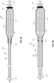
- FIGS. 4A and 4B illustrate another example of an apparatus as described herein, similar to that shown in FIGS. 3A-3C ; in FIGS. 4A-4B , the distal end of the inversion support catheter is configured to have a funnel shape 431, over which the flexible tube may be pulled. Examples of this configuration may be seen, e.g., in U.S. patent application no. 16/594,256 (titled “INVERTING THROMBECTOMY APPARATUSES AND METHODS OF USE”) filed on 10/7/2019 , and U.S. patent application no. 16/594,259, filed on 10/7/2019 .
- the apparatus of FIG. 4A includes an elongate inversion support catheter 402 with the funnel-shaped 431 distal end region, and a flexible tube 406 coupled to a puller 404 within the lumen of the inversion support catheter.
- the proximal end of the flexible tube 415 is compressed (e.g., scrunched) within the inner storage region 417 of the depot 416.
- the proximal end of the sheath may include a hub 421 that may be locked or unlocked onto a hub 412 of the inversion support catheter.
- the puller 404 may also include a hub 414 to help in manipulating the puller and/or for releasably locking to the inversion support catheter.
- the depot 416 may be configured as described above, including having a distal guide 422 that may engage with a sheath, as shown in FIG. 4B .
- FIG. 4B shows the apparatus 400 loaded through the sheath 408 and into a patient, through the patient's skin 411.
- the apparatus is shown engaging with a sheath 408.
- the sheath includes a hub 410 that may engage with the distal end of the depot, as shown.
- the distal guide 422 of the sheath may be inserted into the proximal end of the sheath; the depot may be locked onto the sheath, e.g., sheath hub.
- FIGS. 5A-5B illustrate the operation of the apparatus shown in FIGS. 4A-4B to capture a clot material 550.
- the thrombectomy apparatuses described herein may be advanced in the vessel by moving the sheath 508 and apparatus 500 together or relative to the sheath 508 as shown in FIGS. 5A and 5B.
- FIG. 5A shows a potential starting position
- FIG. 5B shows the apparatus manipulated to ingest material by advancing the inversion support catheter 502 within the sheath while optionally pulling the puller 504 proximally.
- FIG. 5A shows a potential starting position
- FIG. 5B shows the apparatus manipulated to ingest material by advancing the inversion support catheter 502 within the sheath while optionally pulling the puller 504 proximally.
- the inversion support catheter 502 may be locked to the depot, e.g., by a lock (such as a locking mechanism including one or more of: a valve, a clamp, etc.) on the depot, such as the depot hub that releasably locks on to the elongate body of the inversion support catheter 502.
- a control e.g., button, knob, etc.
- the depot 516 may be released from a lock and free to move relative to the elongate inversion support catheter, in this case, allowing the elongate support catheter to be advanced distally 560 as shown.
- the puller 504 may be pulled proximally 570 at the same time.
- the flexible tube 506 may be rolled over the distal end of the inversion support catheter, capturing the material 550, as shown.
- Any of the apparatuses describe described herein may include a lock that releasably locks the depot to the inversion support catheter.
- the flexible tube material may be compressed within the depot and secured in a compressed form.
- the flexible tube may be a woven tube (e.g., a plurality of woven strands) and/or a knitted tube (one or more knit strands), etc.
- the compressed flexible tube may be compressed at a high degree of packing efficiency.
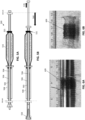
- the depot may hold flexible tube material at a 20 to 1 packing efficiency (e.g., a 10cm long depot could be filled with 200cm of scrunched flexible tube).
- FIGS. 6A-6B illustrate one example of a flexible tube material 609 that is shown compressed on a mandrel from a length of 40 cm to a length of 2 cm.
- FIG. 6A shows the knit material that may be part of a flexible tube compressed down on a 12.5 mm mandrel; in FIG. 6B this compressed flexible tube has been annealed (e.g., via temperature setting) to retain the compressed configuration.
- the material e.g., knitting, weaving, etc.
- the material can then be shape set (e.g., heat set) to any radial diameter (e.g., between 1-30 cm OD).
- the flexible tube can be loaded on a mandrel of equal or small diameter of the heat set diameter, and compressed linearly.
- the flexible tube may be compressed axially so it randomly scrunches.
- a compression guide may be provided to compress the flexible tube in a predictable manner.
- a wire can first be wound around the uncompressed flexible tube on the mandrel (i.e., in a helical pattern) at a given pitch and then the flexible tube and helical wire may be compressed axially ("scrunched"), so the flexible tube is scrunched at the points the wire contacts the flexible tube.
- the flexible tube may then be set (e.g., heat set) in this scrunched configuration.
- the helical wire may be removed before, during or after enclosing in the depot.
- the material may be loaded into a depot in the compressed form including a compression guide (such as the helical wire describe above), with or without shape setting; the compression guide may hold the flexible tube in a compressed form. Once enclosed in the depot, which may itself hold the compressed form, the compression guide may be removed.
- a film, fabric or other layer of material may be included on or in the flexible tube (including the helical wire discussed above), such as on the outside or inside of the flexible tube, that may act like a release, preventing two adjacent compressed regions (e.g., peaks of the fanfold and/or zig-zag shaped flexible tube) from contacting each other within the depot.
- the apparatus may be configured so that the flexible tube is modified after it is compressed, e.g., by twisting, rotating, turning, etc. to further compress and/or to load into the depot.
- the compressed (e.g., scrunched) flexible tube is twisted along its length (e.g., clockwise and/or counterclockwise) on the inversion support catheter, or a mandrel, prior to being enclosed in the inner storage region of the depot.
- the flexible tube within the depot is compressed as described herein and may be further twisted.
- any of the flexible tubes described herein may not be shape-set into the compressed configuration.
- the flexible tube may be heat set to the radius of or slightly larger than the inversion support catheter in the un-inverted (and in some variations an inverted radius may be set, as described above), in a straight/uncompressed configuration, and then compressed and held in the depot. This may reduce the friction will pulling knit out of the depot.
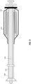
- FIG. 7A illustrates one example of an apparatus 700 as described herein, similar to that shown above, in which the depot 716 includes an inner lining 771 within the inner storage region 707.
- the inner lining may extend over and around the inversion support catheter, and may be rigid or semi-rigid. This inner lining may also be lubricous.
- the depot 716 in FIG. 7A also includes a flushing valve 733 that may be used, for example, for connection to a fluid (e.g., saline) for flushing the depot during or before use.
- the depot includes a hub 721 that may engage with the inversion support catheter 702.
- the sheath 708 (including sheath hub 710) may be configured to engage with the depot (e.g., a distal guide 722 of the depot). In some variations this may be a locking engagement (e.g., a releasable locking engagement). This engagement may be water or pressure-tight (e.g., the depot and the sheath may be sealingly engaged).
- the depot may be pressurized (e.g., by including a pressurized fluid, which may help unfurl the flexible tube 706 when it is pulled distally out of the depot, e.g., by pulling on the puller 704.
- a saline may be injected via the port 733; in some variations, a contrast agent may be introduced through the depot via the same or a different port. Alternatively, or additionally, a lubricant may be injected through the depot.
- the depot can be pressurized with saline or other fluids to produce a positive pressure, which may reduce or stop retrograde patient blood flow into the depot.
- FIG. 7A the distal guide 722 of the depot 716 engages with the sheath 708 by inserting into the sheath.
- FIG. 7B illustrates an example in which the distal end 722 of the depot 716 engages with the sheath 708 by attaching over the sheath. Coupling the depot to the sheath over the sheath may reduce any potential pinch points as the flexible tube unfurls through the sheath. The depot to sheath junction may be sealed in some configurations.
- the flexible tube may be any appropriate material, such as a knit, a weave, a braid, or a non-woven material (both solid and/or laser slotted).
- the flexible tube comprises a metallic material, a polymeric material, and/or mixes of the two.
- the depot can be made from a slippery material such as PTFE, PE, hard polymer.
- the weave can be coated with a lubricious coating, and/or the depot inner chamber can be coated with a lubricious coating.
- the length of the distal end (e.g., distal guide) of the depot can be any length, and may be funnel-shaped or tapered at either or both ends.
- the distal end of the depot can be made from PTFE or lubricious coating.
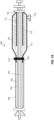
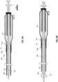
- FIGS. 8A and 8B illustrate two examples of apparatuses including depots having distal guide regions that are longer. The longer distal guide regions may help maintain the compressed form of the flexible tube and may protect and constrain the flexible tube along much of the length of the inversion support catheter, as shown.
- the apparatus 800 includes an inversion support catheter 802, and a flexible tube 806 coupled to a distal end region of a puller 804.
- the apparatus is inserted through the sleeve 808 into the body.
- the distal guide region 822 of the depot 816 extends much further than the introducer sheath 810.
- FIGS. 8A and 8B show the distal guide region extending down much of the length of the inversion support catheter, in some variations, the distal guide region extends between 85% and 20% the length of the inversion support catheter (e.g., 90% or less, 85% or less, 80% or less, 75% or less, 70% or less, 65% or less, 60% or less, 55% or less, 50% or less, 45% or less, etc.).
- FIG. 8A the apparatus is undeployed;
- FIG. 8B shows the apparatus of FIG.
- the short introducer sheath 808 may include a proximal end (e.g., proximal hub 810) that engages with the depot 816.
- proximal hub 810 e.g., proximal hub 810
- FIG. 8B the distal end of the apparatus is inserted through the sheath to clot face, and the distal funnel region 831 may be extended and expanded outwards.
- the proximal end of the sheath e.g., outside of the patient, may be larger in diameter than more distal regions in order to remove pinch point and connect to a wider mouth depot connection junction point.
- the sheath may have a wider mouth with a funnel taper to make the flexible tube deploy with less friction into a smaller sheath ID inside the patient.
- the flexible tube may be compressed in one or more alternative ways.
- the depot 916 includes a layered structure within the inner storage region of the depot, which is divided up into multiple layers 913 to hold the flexible tube 906.
- the device also includes an inversion support catheter 902 and a puller 904 as described above.
- Any of the methods (including user interfaces) described herein may be implemented as software, hardware or firmware, and may be described as a non-transitory computer-readable storage medium storing a set of instructions capable of being executed by a processor (e.g., computer, tablet, smartphone, etc.), that when executed by the processor causes the processor to control perform any of the steps, including but not limited to: displaying, communicating with the user, analyzing, modifying parameters (including timing, frequency, intensity, etc.), determining, alerting, or the like.
- a processor e.g., computer, tablet, smartphone, etc.
- references to a structure or feature that is disposed "adjacent" another feature may have portions that overlap or underlie the adjacent feature.
- the device may be otherwise oriented (rotated 90 degrees or at other orientations) and the spatially relative descriptors used herein interpreted accordingly.
- the terms “upwardly”, “downwardly”, “vertical”, “horizontal” and the like are used herein for the purpose of explanation only unless specifically indicated otherwise.
- first and second may be used herein to describe various features/elements (including steps), these features/elements should not be limited by these terms, unless the context indicates otherwise. These terms may be used to distinguish one feature/element from another feature/element. Thus, a first feature/element discussed below could be termed a second feature/element, and similarly, a second feature/element discussed below could be termed a first feature/element without departing from the teachings of the present invention.
- any of the apparatuses and methods described herein should be understood to be inclusive, but all or a sub-set of the components and/or steps may alternatively be exclusive, and may be expressed as “consisting of” or alternatively “consisting essentially of” the various components, steps, sub-components or sub-steps.
- a numeric value may have a value that is +/- 0.1% of the stated value (or range of values), +/- 1% of the stated value (or range of values), +/- 2% of the stated value (or range of values), +/- 5% of the stated value (or range of values), +/- 10% of the stated value (or range of values), etc.
- Any numerical values given herein should also be understood to include about or approximately that value, unless the context indicates otherwise. For example, if the value "10" is disclosed, then “about 10" is also disclosed. Any numerical range recited herein is intended to include all sub-ranges subsumed therein.
Landscapes
- Health & Medical Sciences (AREA)
- Surgery (AREA)
- Life Sciences & Earth Sciences (AREA)
- Heart & Thoracic Surgery (AREA)
- Nuclear Medicine, Radiotherapy & Molecular Imaging (AREA)
- Vascular Medicine (AREA)
- Engineering & Computer Science (AREA)
- Biomedical Technology (AREA)
- Orthopedic Medicine & Surgery (AREA)
- Medical Informatics (AREA)
- Molecular Biology (AREA)
- Animal Behavior & Ethology (AREA)
- General Health & Medical Sciences (AREA)
- Public Health (AREA)
- Veterinary Medicine (AREA)
- Surgical Instruments (AREA)
Claims (15)
- Vorrichtung (300, 400, 500, 700, 800) zur Entfernung eines Materials aus einem Körperlumen, wobei die Vorrichtung aufweist:einen länglichen Inversionsstützkatheter (302, 402, 502, 702, 802) mit einem proximalen Endbereich, einem distalen Endbereich und einer distalen Endöffnung;einen länglichen Abzieher (304, 404, 504, 704, 804), der sich im Inversionsstützkatheter erstreckt;einen flexiblen Schlauch (306, 406, 506, 706, 806) mit einem distalen ersten Ende,das am Abzieher angebracht ist, wobei sich der flexible Schlauch über einer Außenfläche des Inversionsstützkatheters erstreckt und so konfiguriert ist, dass er in die distale Endöffnung des Inversionsstützkatheters invertiert, wenn am Abzieher proximal gezogen wird; undwobei die Vorrichtung (300, 400, 500, 700, 800) ferner aufweist:
ein Depot (316, 416, 516, 716, 819), das mit dem proximalen Endbereich des Inversionsstützkatheters (302, 402, 502, 702, 802) beweglich gekoppelt ist, wobei das Depot einen Innenlagerbereich (317, 417, 717) aufweist, wobei ein proximaler Abschnitt des flexiblen Schlauchs (306, 406, 506, 706, 806) im Innenlagerbereich (317, 417, 717) komprimiert in einer gefalteten Konfiguration gehalten wird, die so konfiguriert ist, dass sie sich aus einer distalen Endöffnung des Depots (316, 416, 516, 716, 819) entfaltet, wenn am Abzieher proximal gezogen wird. - Vorrichtung (300, 400, 500, 700, 800) nach Anspruch 1, ferner mit einer distalen Führung (322, 422, 722, 822), die die distale Endöffnung des Depots (316, 416, 516, 716, 819) bildet, wobei die distale Führung so konfiguriert ist, dass sie den flexiblen Schlauch (306, 406, 506, 706, 806) aus dem Depot führt, während der flexible Schlauch entfaltet wird.
- Vorrichtung (300, 400, 500, 700, 800) nach Anspruch 2, ferner mit einer Einführschleuse (308, 408, 508, 708, 808), wobei die distale Führung (322, 422, 722, 822) so konfiguriert ist, dass sie einen Eingriff mit der Einführschleuse (308, 408, 508, 708, 808) herstellt, um das Depot an der Einführschleuse zu befestigen.
- Vorrichtung (300, 400, 500, 700, 800) nach Anspruch 3, wobei das Depot (716) so konfiguriert ist, dass es einen Eingriff über einem proximalen Schleusen-Hub (710) der Einführschleuse (708) herstellt,
oder das Depot (316, 416, 516, 819) so konfiguriert ist, dass es einen Eingriff in einem proximalen Schleusen-Hub (310, 410, 510, 810) der Einführschleuse (308, 408, 508, 808) herstellt. - Vorrichtung (300, 400, 500, 700, 800) nach Anspruch 2, wobei sich die distale Führung (322, 422, 722, 822) über der Außenfläche des Inversionsstützkatheters (302, 402, 502, 702, 802) über mehr als 5 cm distal erstreckt
oder die distale Führung (322, 422, 722, 822) ein gleitfähiges Material aufweist: - Vorrichtung (300, 400, 500, 700, 800) nach Anspruch 1, wobei das Depot (316, 416, 516, 716, 819) einen transparenten Außenbereich aufweist, der eine Visualisierung des flexiblen Schlauchs im Innenlagerbereich (317, 417, 717) ermöglicht.
- Vorrichtung (300, 400, 500, 700, 800) nach Anspruch 1, wobei in der gefalteten Konfiguration der flexible Schlauch (306, 406, 506, 706, 806) ein Zickzackmuster aufweist, das parallel oder quer zu einer Längsachse des Inversionsstützkatheters angeordnet ist.
- Vorrichtung (300, 400, 500, 700, 800) nach Anspruch 1, wobei über 50 % einer Länge des flexiblen Schlauchs (306, 406, 506, 706, 806) in einer nicht entfalteten Konfiguration im Depot gehalten werden.
- Vorrichtung (300, 400, 500, 700, 800) nach Anspruch 1, wobei der flexible Schlauch (306, 406, 506, 706, 806) im Innenlagerbereich mit einer über 10-fachen Kompression entlang der Länge des flexiblen Schlauchs komprimiert gehalten wird oder der flexible Schlauch (306, 406, 506, 706, 806) in die gefaltete Konfiguration form eingestellt ist.
- Vorrichtung (700) nach Anspruch 1, ferner mit einem Ventil (733) am Depot (716), das so konfiguriert ist, dass es eine Spüllösung und/oder eine Druck ausübende Lösung aufnimmt,
oder wobei das Depot (716) eine Innenauskleidung (771) aufweist, die zwischen dem Innenlagerbereich (717) und dem Inversionsstützkatheter (702) angeordnet ist. - Vorrichtung (300, 400, 500, 700, 800) nach Anspruch 1, wobei eine oder mehrere Oberflächen des Innenlagerbereichs (317, 417, 717) gleitfähig sind.
- Vorrichtung (300, 400, 500, 700, 800) nach Anspruch 1, wobei das Depot (316, 416, 516, 716, 819) entlang des Inversionsstützkatheters verschiebbar ist.
- Vorrichtung (300, 400, 500, 700, 800) nach Anspruch 1, wobei ein proximales Ende des Depots (316, 416, 516, 716, 819) so konfiguriert ist, dass es sich auf dem proximalen Endbereich des Inversionsstützkatheters (302, 402, 502, 702, 802) verriegelt.
- Vorrichtung (300, 400, 500, 700, 800) nach Anspruch 1, wobei der flexible Schlauch (306, 406, 506, 706, 806) einen Strick- bzw. Wirkschlauch, einen Webschlauch, einen Flechtschlauch, einen Massivschlauch oder einen mittels Laser geschlitzten Schlauch aufweist.
- Vorrichtung (300, 400, 500, 700, 800) nach Anspruch 1, wobei das Depot (316, 416, 516, 716, 819) mit dem proximalen Endbereich des Inversionsstützkatheters (302, 402, 502, 702, 802) verschiebbar gekoppelt ist; und
eine distale Führung (322, 422, 722, 822), die die distale Endöffnung des Depots bildet, wobei die distale Führung (322, 422, 722, 822) so konfiguriert ist, dass sie einen Eingriff mit einer Einführschleuse (308, 408, 508, 708, 808) herstellt und den flexiblen Schlauch (306, 406, 506, 706, 806) aus dem Depot führt, während der flexible Schlauch (306, 406, 506, 706, 806) entfaltet wird.
Applications Claiming Priority (1)
| Application Number | Priority Date | Filing Date | Title |
|---|---|---|---|
| PCT/US2020/014854 WO2021150232A1 (en) | 2020-01-23 | 2020-01-23 | Inverting capture apparatuses having material depots |
Publications (2)
| Publication Number | Publication Date |
|---|---|
| EP4093302A1 EP4093302A1 (de) | 2022-11-30 |
| EP4093302B1 true EP4093302B1 (de) | 2024-05-22 |
Family
ID=69726766
Family Applications (1)
| Application Number | Title | Priority Date | Filing Date |
|---|---|---|---|
| EP20708315.5A Active EP4093302B1 (de) | 2020-01-23 | 2020-01-23 | Umkehrerfassungsvorrichtungen mit materialdepots |
Country Status (3)
| Country | Link |
|---|---|
| US (1) | US12588918B2 (de) |
| EP (1) | EP4093302B1 (de) |
| WO (1) | WO2021150232A1 (de) |
Families Citing this family (2)
| Publication number | Priority date | Publication date | Assignee | Title |
|---|---|---|---|---|
| EP4093302B1 (de) | 2020-01-23 | 2024-05-22 | Stryker Corporation | Umkehrerfassungsvorrichtungen mit materialdepots |
| US20250099119A1 (en) * | 2023-09-26 | 2025-03-27 | Boston Scientific Scimed, Inc. | Thrombectomy apparatus |
Family Cites Families (199)
| Publication number | Priority date | Publication date | Assignee | Title |
|---|---|---|---|---|
| US1013038A (en) | 1910-04-14 | 1911-12-26 | John Mitchell | Construction of buildings. |
| US1001626A (en) | 1910-05-05 | 1911-08-29 | Thomas E Dockery | Device for making expansion-joints in concrete-work. |
| US1001033A (en) | 1910-11-25 | 1911-08-22 | Harold P Mcentee | Railway-car-moving device. |
| US1002875A (en) | 1911-04-06 | 1911-09-12 | Peter Jacob Adolph Schnoor | Swivel. |
| US1027186A (en) | 1911-12-04 | 1912-05-21 | Margaret S Dambach | Smoke-bell. |
| US1032788A (en) | 1912-03-22 | 1912-07-16 | Frank Slacinski | Curtain-pole. |
| US3515137A (en) | 1966-10-26 | 1970-06-02 | Deseret Pharma | Intravenous catheter unit with inserter means for sequential feeding of catheter |
| GB1588072A (en) | 1977-02-11 | 1981-04-15 | Beecher W H | Extracting device for removing objects from human body passages |
| US4222380A (en) | 1977-12-02 | 1980-09-16 | Olympus Optical Co., Ltd. | Celiac injector |
| US4324262A (en) | 1979-01-02 | 1982-04-13 | University Of Virginia Alumni Patents Foundation | Aspirating culture catheter and method of use |
| US4243040A (en) | 1979-09-17 | 1981-01-06 | Beecher William H | Extracting device for removing objects from human body passages |
| US4469100A (en) * | 1983-03-14 | 1984-09-04 | Hardwick Charles W | Intussuscepting balloon catheter for stone extraction |
| US4604094A (en) | 1984-09-06 | 1986-08-05 | The United States Of America As Represented By The Secretary Of The Department Of Health And Human Services | Toposcopic catheter and method of fabrication |
| US4646736A (en) | 1984-09-10 | 1987-03-03 | E. R. Squibb & Sons, Inc. | Transluminal thrombectomy apparatus |
| US4863440A (en) | 1985-12-23 | 1989-09-05 | Thomas J. Fogarty | Pressurized manual advancement dilatation catheter |
| US5091316A (en) | 1988-06-09 | 1992-02-25 | Becton, Dickinson And Company | Biological sample collection and transport device |
| US4946440A (en) | 1988-10-05 | 1990-08-07 | Hall John E | Evertible membrane catheter and method of use |
| US5011488A (en) | 1988-12-07 | 1991-04-30 | Robert Ginsburg | Thrombus extraction system |
| US5236423A (en) * | 1988-12-13 | 1993-08-17 | Endomed Corporation | Facilitating endoscopy |
| US5329923A (en) | 1991-02-15 | 1994-07-19 | Lundquist Ingemar H | Torquable catheter |
| US5364345A (en) | 1991-10-18 | 1994-11-15 | Imagyn Medical, Inc. | Method of tubal recanalization and catheter system therefor |
| EP0539084A1 (de) | 1991-10-18 | 1993-04-28 | Imagyn Medical, Inc. | Vorrichtung und Verfahren zur unabhängigen Bewegung eines Instrumentes in einem lineären ausstülpbaren Katheter |
| US5389100A (en) | 1991-11-06 | 1995-02-14 | Imagyn Medical, Inc. | Controller for manipulation of instruments within a catheter |
| ATE232067T1 (de) | 1995-04-14 | 2003-02-15 | Boston Scient Ltd | Stentanbringungsvorrichtung mit rollmembran |
| US5971938A (en) | 1996-04-02 | 1999-10-26 | Hart; Charles C. | Access device with expandable containment member |
| US5814064A (en) | 1997-03-06 | 1998-09-29 | Scimed Life Systems, Inc. | Distal protection device |
| WO1998039053A1 (en) | 1997-03-06 | 1998-09-11 | Scimed Life Systems, Inc. | Distal protection device and method |
| EP1011532B1 (de) | 1997-04-23 | 2014-05-07 | Ethicon Endo-Surgery, Inc. | Abzweigender stent und distales schutzsystem |
| US5908435A (en) | 1997-10-23 | 1999-06-01 | Samuels; Shaun L. W. | Expandable lumen device and method of use |
| US20040199202A1 (en) | 1997-11-12 | 2004-10-07 | Genesis Technologies Llc | Biological passageway occlusion removal |
| ATE404123T1 (de) | 1997-11-12 | 2008-08-15 | Genesis Technologies Llc | Vorrichtung zum entfernen von okklusionen in biologischen durchgängen |
| US20100030256A1 (en) | 1997-11-12 | 2010-02-04 | Genesis Technologies Llc | Medical Devices and Methods |
| DE69941894D1 (de) | 1998-02-10 | 2010-02-25 | Artemis Medical Inc | Okklusions-, verankerungs-, span- oder stromsteuergerät |
| WO1999039648A1 (en) | 1998-02-10 | 1999-08-12 | Dubrul William R | Entrapping apparatus and method for use |
| US6544278B1 (en) | 1998-11-06 | 2003-04-08 | Scimed Life Systems, Inc. | Rolling membrane stent delivery system |
| WO2000032118A1 (en) | 1998-12-01 | 2000-06-08 | Atropos Limited | A medical device comprising an evertable sleeve |
| US6156055A (en) | 1999-03-23 | 2000-12-05 | Nitinol Medical Technologies Inc. | Gripping device for implanting, repositioning or extracting an object within a body vessel |
| JP3533107B2 (ja) | 1999-04-26 | 2004-05-31 | ペンタックス株式会社 | 内視鏡用スネア |
| US6350271B1 (en) | 1999-05-17 | 2002-02-26 | Micrus Corporation | Clot retrieval device |
| EP1194074A4 (de) | 1999-05-19 | 2002-09-11 | Innerdyne Medical Inc | System und verfahren um vaskulären zugriff zu ermöglichen |
| US6620179B2 (en) | 1999-08-10 | 2003-09-16 | Neurovasx, Inc. | Clot disrupting wire/catheter assembly |
| US20030153873A1 (en) | 2000-03-13 | 2003-08-14 | Luther Ronald B. | Hard tip over-the-needle intravenous catheter |
| AUPQ641400A0 (en) * | 2000-03-23 | 2000-04-15 | Kleiner, Daniel E. | A device incorporating a hollow member for being positioned along a body cavity of a patient and method of positioning same |
| US7727242B2 (en) | 2000-06-29 | 2010-06-01 | Concentric Medical, Inc. | Systems, methods and devices for removing obstructions from a blood vessel |
| US8298257B2 (en) | 2000-06-29 | 2012-10-30 | Concentric Medical, Inc. | Systems, methods and devices for removing obstructions from a blood vessel |
| EP1296728A4 (de) | 2000-06-29 | 2009-09-09 | Concentric Medical Inc | Systeme, verfahren und vorrichtungen zut entfernung von blokaden aus einem blutgefäss |
| US7766921B2 (en) | 2000-06-29 | 2010-08-03 | Concentric Medical, Inc. | Systems, methods and devices for removing obstructions from a blood vessel |
| WO2002019899A2 (en) * | 2000-09-05 | 2002-03-14 | Medevert Limited | Body cavity liner |
| US6569181B1 (en) | 2000-12-20 | 2003-05-27 | Advanced Cardiovascular Systems, Inc. | Stent retrieval system |
| ES2202269T3 (es) | 2001-05-03 | 2004-04-01 | Radi Medical Systems Ab | Util de guiado para cierre de heridas. |
| US6635070B2 (en) | 2001-05-21 | 2003-10-21 | Bacchus Vascular, Inc. | Apparatus and methods for capturing particulate material within blood vessels |
| JP2003038500A (ja) | 2001-08-03 | 2003-02-12 | Mti Kk | 管状器官内の異物除去用ブラシつきシャフト |
| US6846029B1 (en) | 2001-08-09 | 2005-01-25 | Gary Dean Ragner | Torus-shaped mechanical gripper |
| US7063714B2 (en) | 2001-08-22 | 2006-06-20 | Gore Enterprise Holdings, Inc. | Apparatus and methods for treating stroke and controlling cerebral flow characteristics |
| JP4043216B2 (ja) | 2001-10-30 | 2008-02-06 | オリンパス株式会社 | ステント |
| US7147656B2 (en) | 2001-12-03 | 2006-12-12 | Xtent, Inc. | Apparatus and methods for delivery of braided prostheses |
| US20030176884A1 (en) | 2002-03-12 | 2003-09-18 | Marwane Berrada | Everted filter device |
| US6866679B2 (en) | 2002-03-12 | 2005-03-15 | Ev3 Inc. | Everting stent and stent delivery system |
| US8070769B2 (en) | 2002-05-06 | 2011-12-06 | Boston Scientific Scimed, Inc. | Inverted embolic protection filter |
| US6830561B2 (en) | 2002-05-08 | 2004-12-14 | Scimed Life Systems, Inc. | Catheter with protective sleeve |
| US7232452B2 (en) | 2002-07-12 | 2007-06-19 | Ev3 Inc. | Device to create proximal stasis |
| US7736300B2 (en) | 2003-04-14 | 2010-06-15 | Softscope Medical Technologies, Inc. | Self-propellable apparatus and method |
| US8388630B2 (en) | 2003-09-18 | 2013-03-05 | Boston Scientific Scimed, Inc. | Medical retrieval devices and methods |
| US20050085826A1 (en) | 2003-10-21 | 2005-04-21 | Scimed Life Systems, Inc. | Unfolding balloon catheter for proximal embolus protection |
| NL1027728C2 (nl) | 2003-12-24 | 2005-07-05 | Kedge Holding Bv | Zekeringsinrichting voor een valbeveiliging. |
| US20050245876A1 (en) | 2003-12-24 | 2005-11-03 | Accessclosure, Inc. | Apparatus and methods for facilitating access through a puncture including sealing compound therein |
| US7637903B2 (en) | 2004-02-09 | 2009-12-29 | Cryocor, Inc. | Catheter articulation segment with alternating cuts |
| EP1715795B1 (de) | 2004-02-19 | 2008-12-10 | Applied Medical Resources Corporation | Embolektomie-fangschleuse |
| JP4638683B2 (ja) | 2004-03-25 | 2011-02-23 | テルモ株式会社 | 血管内異物除去吸引用カテーテル |
| WO2005094283A2 (en) | 2004-03-25 | 2005-10-13 | Hauser David L | Vascular filter device |
| US20050228417A1 (en) | 2004-03-26 | 2005-10-13 | Teitelbaum George P | Devices and methods for removing a matter from a body cavity of a patient |
| US20160022293A1 (en) | 2004-04-15 | 2016-01-28 | Genesis Technologies Llc | Medical device and method |
| US8623067B2 (en) | 2004-05-25 | 2014-01-07 | Covidien Lp | Methods and apparatus for luminal stenting |
| US20050283166A1 (en) | 2004-06-17 | 2005-12-22 | Secant Medical, Llc | Expandible snare |
| US20060047286A1 (en) | 2004-08-31 | 2006-03-02 | Stephen West | Clot retrieval device |
| CN100529637C (zh) | 2004-09-01 | 2009-08-19 | 鸿富锦精密工业(深圳)有限公司 | 热管的制备方法 |
| US20060173525A1 (en) | 2005-02-02 | 2006-08-03 | Percutaneous Systems, Inc. | Methods and systems for deploying luminal prostheses |
| US7632296B2 (en) | 2005-03-03 | 2009-12-15 | Boston Scientific Scimed, Inc. | Rolling membrane with hydraulic recapture means for self expanding stent |
| US20060293696A1 (en) | 2005-04-18 | 2006-12-28 | Salviac Limited | Retrieval catheter |
| US8663312B2 (en) | 2005-05-27 | 2014-03-04 | Hlt, Inc. | Intravascular cuff |
| US8343170B2 (en) | 2005-08-12 | 2013-01-01 | Massicotte J Mathieu | Method and device for extracting objects from the body |
| US7905841B2 (en) | 2005-08-31 | 2011-03-15 | Boston Scientific Scimed, Inc. | Cytology device and related methods of use |
| US20070123798A1 (en) | 2005-10-07 | 2007-05-31 | Tsion Israel Medical Systems Ltd. | Contamination protection device and method for use |
| US8252017B2 (en) * | 2005-10-18 | 2012-08-28 | Cook Medical Technologies Llc | Invertible filter for embolic protection |
| US20070149996A1 (en) | 2005-12-28 | 2007-06-28 | Medtronic Vascular, Inc. | Low profile filter |
| WO2008088371A2 (en) | 2006-06-16 | 2008-07-24 | Xcellerex, Inc. | Gas delivery configurations, foam control systems, and bag molding methods and articles for collapsible bag vessels and bioreactors |
| AU2007282219B2 (en) | 2006-08-07 | 2013-06-20 | Nsure Holding B.V. | Quality control of agricultural products based on gene expression |
| DE102006044831A1 (de) | 2006-09-20 | 2008-04-03 | Phenox Gmbh | Vorrichtung zur Entfernung von Thromben aus Blutgefäßen |
| US7722568B2 (en) | 2007-01-29 | 2010-05-25 | Onset Medical Corporation | Expandable intra-aortic balloon pump sheath |
| US9144462B2 (en) | 2007-01-30 | 2015-09-29 | Merit Medical Systems, Inc. | Introducer sheath and hub assembly |
| US9358037B2 (en) | 2007-06-26 | 2016-06-07 | Roxwood Medical, Inc. | Method and apparatus for centering a microcatheter within a vasculature |
| US9125683B2 (en) | 2007-06-26 | 2015-09-08 | Roxwood Medical Inc. | Method and apparatus for placing a catheter within a vasculature |
| US8128592B2 (en) | 2007-07-11 | 2012-03-06 | Apollo Endosurgery, Inc. | Methods and systems for performing submucosal medical procedures |
| US20090076417A1 (en) | 2007-08-08 | 2009-03-19 | Gregory Allen Jones | Glide Clip |
| CN201079423Y (zh) | 2007-09-29 | 2008-07-02 | 成正辉 | 血管内血栓及栓塞物切除器 |
| US8066757B2 (en) | 2007-10-17 | 2011-11-29 | Mindframe, Inc. | Blood flow restoration and thrombus management methods |
| WO2009086482A1 (en) | 2007-12-26 | 2009-07-09 | Lazarus Effect, Inc. | Retrieval systems and methods for use thereof |
| US9034008B2 (en) | 2008-08-29 | 2015-05-19 | Rapid Medical Ltd. | Device and method involving stabilization during clot removal |
| US8721714B2 (en) | 2008-09-17 | 2014-05-13 | Medtronic Corevalve Llc | Delivery system for deployment of medical devices |
| EP2344051B1 (de) | 2008-09-22 | 2016-11-09 | Hotspur Technologies, Inc | Flusswiederherstellungssysteme |
| US8057496B2 (en) | 2008-10-06 | 2011-11-15 | Cook Medical Technologies Llc | Mechanical thrombectomy device |
| EP2355717B1 (de) | 2008-12-01 | 2014-02-19 | Percutaneous Systems, Inc. | Systeme zur Erfassung und Entfernung von Harnsteinen aus Körperhohlräumen |
| GB0823658D0 (en) | 2008-12-30 | 2009-02-04 | Angiomed Ag | Stent delivery device |
| US8672835B2 (en) | 2009-02-16 | 2014-03-18 | Fujifilm Corporation | Propellable apparatus and related methods |
| EP2403583B1 (de) | 2009-03-06 | 2016-10-19 | Lazarus Effect, Inc. | Abfragesysteme |
| US20100249815A1 (en) | 2009-03-25 | 2010-09-30 | Cook Incorporated | Everted sheath thrombectomy device |
| AU2015210338B2 (en) | 2009-06-24 | 2018-02-01 | Shifamed Holdings, Llc | Steerable medical delivery devices and methods of use |
| US20110034987A1 (en) | 2009-08-04 | 2011-02-10 | Kennedy Kenneth C | Roll sleeve mechanism for proximal release stent |
| US20110118817A1 (en) | 2009-11-17 | 2011-05-19 | Boston Scientific Scimed, Inc. | Stent delivery system |
| WO2011091383A1 (en) | 2010-01-22 | 2011-07-28 | Lazarus Effect, Inc. | Retrieval systems and methods for use thereof |
| EP2533729A1 (de) | 2010-02-08 | 2012-12-19 | Surpass Medical Ltd | Verfahren und vorrichtung zur behandlung zerebrovaskulärer erkrankungen und verabreichungssystem dafür |
| US9126016B2 (en) | 2010-05-19 | 2015-09-08 | Nfusion Vascular Systems Llc | Augmented delivery catheter and method |
| JP4846044B1 (ja) | 2010-06-30 | 2011-12-28 | テルモ株式会社 | 医療用装置 |
| WO2012009675A2 (en) | 2010-07-15 | 2012-01-19 | Lazarus Effect, Inc. | Retrieval systems and methods for use thereof |
| US10039900B2 (en) | 2010-09-07 | 2018-08-07 | Angiodynamics, Inc. | Fluid delivery and treatment device and method of use |
| US8858497B2 (en) | 2010-09-07 | 2014-10-14 | Angio Dynamics, Inc. | Device and method for removing material from a hollow anatomical structure |
| US9039749B2 (en) | 2010-10-01 | 2015-05-26 | Covidien Lp | Methods and apparatuses for flow restoration and implanting members in the human body |
| US9795408B2 (en) | 2010-10-06 | 2017-10-24 | Cruzar Medsystems, Inc. | Catheter with vessel lining and methods for using same |
| WO2012049652A1 (en) | 2010-10-15 | 2012-04-19 | Endogrowth (Proprietary) Limited | An inversible tubular member and a gripping device including such a member |
| ES3029850T3 (en) | 2011-03-09 | 2025-06-25 | Neuravi Ltd | A clot retrieval device for removing occlusive clot from a blood vessel |
| WO2012132725A1 (ja) | 2011-03-25 | 2012-10-04 | 富士フイルム株式会社 | 自己推進装置 |
| WO2012141748A1 (en) * | 2011-04-11 | 2012-10-18 | Upstream Peripheral Technologies | Needle and guidewire holder |
| US9107576B2 (en) | 2011-04-20 | 2015-08-18 | Fujifilm Corporation | Endoscope insertion assisting device |
| EP3398539B1 (de) | 2011-05-23 | 2020-08-26 | Covidien LP | Abfragesysteme |
| US11026708B2 (en) | 2011-07-26 | 2021-06-08 | Thrombx Medical, Inc. | Intravascular thromboembolectomy device and method using the same |
| US8784442B2 (en) | 2011-08-19 | 2014-07-22 | Empirilon Technology, Llc | Methods and systems for performing thrombectomy procedures |
| US10010437B2 (en) | 2011-10-17 | 2018-07-03 | W. L. Gore & Associates, Inc. | Endoluminal device retrieval devices and related systems and methods |
| GB2498349B (en) | 2012-01-10 | 2013-12-11 | Cook Medical Technologies Llc | Object capture device |
| US20130267870A1 (en) | 2012-04-06 | 2013-10-10 | Histologics Llc | Cell and tissue collection method and device |
| US9445828B2 (en) | 2012-07-05 | 2016-09-20 | Cognition Medical Corp. | Methods, devices, and systems for postconditioning with clot removal |
| ES2704498T3 (es) | 2012-07-29 | 2019-03-18 | Vvt Medical Ltd | Catéter de ablación para ablación de vasos sanguíneos y métodos para su uso |
| KR20180002898A (ko) | 2012-08-03 | 2018-01-08 | 제이.디. 프랑코 앤 컴퍼니 | 안동맥의 폐색을 치료하기 위한 장비 및 방법 |
| US9308007B2 (en) | 2012-08-14 | 2016-04-12 | W. L. Gore & Associates, Inc. | Devices and systems for thrombus treatment |
| CN202988096U (zh) | 2012-11-28 | 2013-06-12 | 信发科技开发有限公司 | 新型刮板机刮板 |
| US11179143B2 (en) | 2013-02-01 | 2021-11-23 | Boston Scientific Scimed, Inc. | Systems, methods, and devices for fallopian tube diagnostics |
| CN104000635B (zh) | 2013-02-21 | 2018-02-16 | 微创神通医疗科技(上海)有限公司 | 取栓器及取栓装置 |
| EP2967613B1 (de) | 2013-03-11 | 2020-04-22 | Boston Scientific Scimed, Inc. | Griffe für eine medizinische vorrichtung |
| US20140276403A1 (en) | 2013-03-13 | 2014-09-18 | DePuy Synthes Products, LLC | Ischemic stroke device |
| SI2967610T1 (sl) | 2013-03-14 | 2019-07-31 | Neuravi Limited | Naprava za odkrivanje strdka za odstranjevanje okluzivnega strdka in krvne žile |
| CN104068910A (zh) | 2013-03-26 | 2014-10-01 | 上海微创医疗器械(集团)有限公司 | 血管取栓系统 |
| US10258455B2 (en) | 2013-04-12 | 2019-04-16 | Don Michael International, Llc | Apparatus and procedure for trapping embolic debris |
| US10188411B2 (en) | 2013-04-16 | 2019-01-29 | Calcula Technologies, Inc. | Everting balloon for medical devices |
| US20140330286A1 (en) | 2013-04-25 | 2014-11-06 | Michael P. Wallace | Methods and Devices for Removing Obstructing Material From the Human Body |
| US20140364896A1 (en) | 2013-06-07 | 2014-12-11 | Abott Cardiovascular Systems, Inc. | Device, system, and method for thrombus retrieval |
| KR101455630B1 (ko) | 2013-06-30 | 2014-10-28 | 안지용 | 수동식 혈전 절제 기구 |
| US20150018860A1 (en) | 2013-07-12 | 2015-01-15 | Inceptus Medical, Llc | Methods and apparatus for treating small vessel thromboembolisms |
| US9782186B2 (en) | 2013-08-27 | 2017-10-10 | Covidien Lp | Vascular intervention system |
| US9814477B2 (en) | 2013-09-24 | 2017-11-14 | Cook Medical Technologies Llc | Clot retrieval system with inverted sleeve |
| US10383644B2 (en) | 2013-10-17 | 2019-08-20 | Covidien Lp | Mechanical thrombectomy with proximal occlusion |
| US9028401B1 (en) | 2013-11-11 | 2015-05-12 | Cross Bay Medical, Inc. | Apparatus and methods for accessing and sealing bodily vessels and cavities |
| US10327883B2 (en) | 2013-11-28 | 2019-06-25 | Innovations Ltd. | Filtration and entrapment apparatus and method of use |
| WO2015102382A1 (ko) | 2014-01-02 | 2015-07-09 | 엘지이노텍(주) | 렌즈 구동 장치 및 이를 포함하는 카메라 모듈 |
| US9155552B2 (en) | 2014-01-03 | 2015-10-13 | Legacy Ventures LLC | Clot retrieval system |
| US9060777B1 (en) | 2014-05-28 | 2015-06-23 | Tw Medical Technologies, Llc | Vaso-occlusive devices and methods of use |
| CN105792879A (zh) | 2014-06-04 | 2016-07-20 | 恩菲纽姆血管技术有限公司 | 低径向力血管设备和闭塞方法 |
| US10792056B2 (en) | 2014-06-13 | 2020-10-06 | Neuravi Limited | Devices and methods for removal of acute blockages from blood vessels |
| JP6595513B2 (ja) | 2014-06-13 | 2019-10-23 | ニューラヴィ・リミテッド | 血管からの急性閉塞物の除去のための装置 |
| US9801643B2 (en) | 2014-09-02 | 2017-10-31 | Cook Medical Technologies Llc | Clot retrieval catheter |
| US9351747B2 (en) | 2014-09-10 | 2016-05-31 | Vascular Solutions, Inc. | Capture assembly and method |
| US20160074627A1 (en) | 2014-09-15 | 2016-03-17 | Orbusneich Medical, Inc. | Vascular Re-entry Catheter |
| CN104523320A (zh) | 2015-01-12 | 2015-04-22 | 上海英诺伟医疗器械有限公司 | 一种一次性使用的取石网篮 |
| ES2577288B8 (es) | 2015-01-13 | 2019-01-10 | Anaconda Biomed S L | Dispositivo para trombectomía |
| GB2534193A (en) | 2015-01-16 | 2016-07-20 | Cook Medical Technologies Llc | Ablation Apparatus with Thrombus Detachment Mechanism |
| US10524810B2 (en) | 2015-03-04 | 2020-01-07 | Gyrus Acmi, Inc. | Medical device for capturing stone fragments |
| CN113116459B (zh) | 2015-08-06 | 2025-01-10 | 瓦斯科尔勒治疗股份有限公司 | 轴向伸长的血栓捕获系统 |
| US10179046B2 (en) | 2015-08-14 | 2019-01-15 | Edwards Lifesciences Corporation | Gripping and pushing device for medical instrument |
| CN108348319B (zh) | 2015-09-28 | 2020-03-10 | 斯瑞克公司 | 机械取栓装置和方法 |
| US20170100142A1 (en) | 2015-10-09 | 2017-04-13 | Incuvate, Llc | Systems and methods for management of thrombosis |
| US9700332B2 (en) | 2015-10-23 | 2017-07-11 | Inari Medical, Inc. | Intravascular treatment of vascular occlusion and associated devices, systems, and methods |
| US9955986B2 (en) | 2015-10-30 | 2018-05-01 | Auris Surgical Robotics, Inc. | Basket apparatus |
| US10262858B2 (en) | 2016-04-25 | 2019-04-16 | Applied Materials, Inc. | Surface functionalization and passivation with a control layer |
| US10888342B2 (en) | 2016-04-25 | 2021-01-12 | Stryker Corporation | Anti-jamming and macerating thrombectomy apparatuses and methods |
| US11896247B2 (en) | 2016-04-25 | 2024-02-13 | Stryker Corporation | Inverting mechanical thrombectomy apparatuses |
| US11497512B2 (en) | 2016-04-25 | 2022-11-15 | Stryker Corporation | Inverting thrombectomy apparatuses and methods |
| JP6924256B2 (ja) | 2016-04-25 | 2021-08-25 | ストライカー コーポレイションStryker Corporation | 予め組み込まれた反転トラクタの血栓除去装置および方法 |
| CN109414272B (zh) | 2016-04-25 | 2021-09-28 | 斯瑞克公司 | 翻转机械血栓切除装置及在血管系统中使用的方法 |
| US10517624B2 (en) | 2016-06-03 | 2019-12-31 | Stryker Corporation | Inverting thrombectomy apparatuses and methods |
| US10799261B2 (en) | 2016-08-18 | 2020-10-13 | Boston Scientific Scimed, Inc. | Retaining polypectomy device |
| JP2019526381A (ja) | 2016-09-12 | 2019-09-19 | ストライカー コーポレイションStryker Corporation | 自己転動血栓除去装置及び方法 |
| US10098651B2 (en) | 2017-01-10 | 2018-10-16 | Inari Medical, Inc. | Devices and methods for treating vascular occlusion |
| WO2018148174A1 (en) | 2017-02-08 | 2018-08-16 | Kp Medcure, Inc. | Axial lengthening thrombus capture system |
| JP2020508153A (ja) | 2017-02-23 | 2020-03-19 | ボストン サイエンティフィック サイムド,インコーポレイテッドBoston Scientific Scimed,Inc. | 医療デバイスと共に使用する装填器具 |
| US11191555B2 (en) | 2017-05-12 | 2021-12-07 | Covidien Lp | Retrieval of material from vessel lumens |
| US11298145B2 (en) | 2017-05-12 | 2022-04-12 | Covidien Lp | Retrieval of material from vessel lumens |
| US11129630B2 (en) | 2017-05-12 | 2021-09-28 | Covidien Lp | Retrieval of material from vessel lumens |
| CN110913778B (zh) | 2017-07-06 | 2023-04-14 | 斯瑞克公司 | 倒置血栓切除装置和方法 |
| EP4176830A1 (de) | 2017-11-09 | 2023-05-10 | Stryker Corporation | Invertierende thrombektomievorrichtungen mit verbesserter verfolgung |
| CN112423683B (zh) | 2018-05-14 | 2024-06-18 | 史赛克公司 | 翻转血栓切除装置及使用方法 |
| EP4434572A3 (de) | 2018-05-16 | 2024-11-20 | Abiomed, Inc. | Abziehbare schleusenanordnung |
| US10898216B2 (en) | 2018-06-13 | 2021-01-26 | DePuy Synthes Products, Inc. | Vasculature obstruction capture device |
| EP3849440A1 (de) | 2018-09-10 | 2021-07-21 | Stryker Corporation | Lasergeschlitzte aufnahmevorrichtung |
| ES2908031T3 (es) | 2018-09-10 | 2022-04-27 | Stryker Corp | Aparatos de trombectomía de inversión |
| EP4295789B1 (de) | 2019-03-04 | 2025-07-30 | Neuravi Limited | Trichterbetätigungssysteme |
| WO2020210840A1 (en) | 2019-04-11 | 2020-10-15 | GW Medical LLC | Small tube tissue biopsy |
| US20220322920A1 (en) * | 2019-05-30 | 2022-10-13 | University Of Washington | Endoscope Steering Mechanism with Everted Tube Introducer |
| US11529495B2 (en) | 2019-09-11 | 2022-12-20 | Neuravi Limited | Expandable mouth catheter |
| EP4093302B1 (de) | 2020-01-23 | 2024-05-22 | Stryker Corporation | Umkehrerfassungsvorrichtungen mit materialdepots |
| EP4442212A3 (de) | 2020-02-11 | 2024-12-18 | Stryker Corporation | Anti-lock-thrombektomievorrichtungen |
| WO2021167594A1 (en) | 2020-02-18 | 2021-08-26 | Stryker Corporation | Systems and methods for removing material from a vessel |
-
2020
- 2020-01-23 EP EP20708315.5A patent/EP4093302B1/de active Active
- 2020-01-23 WO PCT/US2020/014854 patent/WO2021150232A1/en not_active Ceased
-
2022
- 2022-07-18 US US17/867,423 patent/US12588918B2/en active Active
Also Published As
| Publication number | Publication date |
|---|---|
| EP4093302A1 (de) | 2022-11-30 |
| WO2021150232A1 (en) | 2021-07-29 |
| US12588918B2 (en) | 2026-03-31 |
| US20220346815A1 (en) | 2022-11-03 |
Similar Documents
| Publication | Publication Date | Title |
|---|---|---|
| US12295601B2 (en) | Inverting thrombectomy apparatuses having enhanced tracking | |
| US10729459B2 (en) | Flow restoration systems and methods for use | |
| EP3984477A1 (de) | Invertierende thrombektomievorrichtungen | |
| US6602280B2 (en) | Delivery system and method for expandable intracorporeal device | |
| EP2544603B1 (de) | Anordnung zur beseitigung von obstruktionen | |
| US20130310803A1 (en) | Clot Removal Device and Method of Using Same | |
| US12588918B2 (en) | Inverting capture apparatuses having material depots | |
| US11304834B2 (en) | Retractor device for transforming a retrieval device from a deployed position to a delivery position | |
| EP3359240B1 (de) | System zum lösen einer vorrichtung aus einem führungsdraht | |
| WO2021167594A1 (en) | Systems and methods for removing material from a vessel |
Legal Events
| Date | Code | Title | Description |
|---|---|---|---|
| STAA | Information on the status of an ep patent application or granted ep patent |
Free format text: STATUS: UNKNOWN |
|
| STAA | Information on the status of an ep patent application or granted ep patent |
Free format text: STATUS: THE INTERNATIONAL PUBLICATION HAS BEEN MADE |
|
| PUAI | Public reference made under article 153(3) epc to a published international application that has entered the european phase |
Free format text: ORIGINAL CODE: 0009012 |
|
| STAA | Information on the status of an ep patent application or granted ep patent |
Free format text: STATUS: REQUEST FOR EXAMINATION WAS MADE |
|
| 17P | Request for examination filed |
Effective date: 20220821 |
|
| AK | Designated contracting states |
Kind code of ref document: A1 Designated state(s): AL AT BE BG CH CY CZ DE DK EE ES FI FR GB GR HR HU IE IS IT LI LT LU LV MC MK MT NL NO PL PT RO RS SE SI SK SM TR |
|
| DAV | Request for validation of the european patent (deleted) | ||
| DAX | Request for extension of the european patent (deleted) | ||
| GRAP | Despatch of communication of intention to grant a patent |
Free format text: ORIGINAL CODE: EPIDOSNIGR1 |
|
| STAA | Information on the status of an ep patent application or granted ep patent |
Free format text: STATUS: GRANT OF PATENT IS INTENDED |
|
| INTG | Intention to grant announced |
Effective date: 20240104 |
|
| GRAS | Grant fee paid |
Free format text: ORIGINAL CODE: EPIDOSNIGR3 |
|
| GRAA | (expected) grant |
Free format text: ORIGINAL CODE: 0009210 |
|
| STAA | Information on the status of an ep patent application or granted ep patent |
Free format text: STATUS: THE PATENT HAS BEEN GRANTED |
|
| AK | Designated contracting states |
Kind code of ref document: B1 Designated state(s): AL AT BE BG CH CY CZ DE DK EE ES FI FR GB GR HR HU IE IS IT LI LT LU LV MC MK MT NL NO PL PT RO RS SE SI SK SM TR |
|
| REG | Reference to a national code |
Ref country code: GB Ref legal event code: FG4D |
|
| REG | Reference to a national code |
Ref country code: CH Ref legal event code: EP |
|
| REG | Reference to a national code |
Ref country code: DE Ref legal event code: R096 Ref document number: 602020031240 Country of ref document: DE |
|
| REG | Reference to a national code |
Ref country code: IE Ref legal event code: FG4D |
|
| REG | Reference to a national code |
Ref country code: NL Ref legal event code: FP |
|
| REG | Reference to a national code |
Ref country code: LT Ref legal event code: MG9D |
|
| PG25 | Lapsed in a contracting state [announced via postgrant information from national office to epo] |
Ref country code: IS Free format text: LAPSE BECAUSE OF FAILURE TO SUBMIT A TRANSLATION OF THE DESCRIPTION OR TO PAY THE FEE WITHIN THE PRESCRIBED TIME-LIMIT Effective date: 20240922 |
|
| PG25 | Lapsed in a contracting state [announced via postgrant information from national office to epo] |
Ref country code: BG Free format text: LAPSE BECAUSE OF FAILURE TO SUBMIT A TRANSLATION OF THE DESCRIPTION OR TO PAY THE FEE WITHIN THE PRESCRIBED TIME-LIMIT Effective date: 20240522 |
|
| PG25 | Lapsed in a contracting state [announced via postgrant information from national office to epo] |
Ref country code: FI Free format text: LAPSE BECAUSE OF FAILURE TO SUBMIT A TRANSLATION OF THE DESCRIPTION OR TO PAY THE FEE WITHIN THE PRESCRIBED TIME-LIMIT Effective date: 20240522 Ref country code: HR Free format text: LAPSE BECAUSE OF FAILURE TO SUBMIT A TRANSLATION OF THE DESCRIPTION OR TO PAY THE FEE WITHIN THE PRESCRIBED TIME-LIMIT Effective date: 20240522 |
|
| PG25 | Lapsed in a contracting state [announced via postgrant information from national office to epo] |
Ref country code: GR Free format text: LAPSE BECAUSE OF FAILURE TO SUBMIT A TRANSLATION OF THE DESCRIPTION OR TO PAY THE FEE WITHIN THE PRESCRIBED TIME-LIMIT Effective date: 20240823 |
|
| PG25 | Lapsed in a contracting state [announced via postgrant information from national office to epo] |
Ref country code: PT Free format text: LAPSE BECAUSE OF FAILURE TO SUBMIT A TRANSLATION OF THE DESCRIPTION OR TO PAY THE FEE WITHIN THE PRESCRIBED TIME-LIMIT Effective date: 20240923 |
|
| REG | Reference to a national code |
Ref country code: AT Ref legal event code: MK05 Ref document number: 1688136 Country of ref document: AT Kind code of ref document: T Effective date: 20240522 |
|
| PG25 | Lapsed in a contracting state [announced via postgrant information from national office to epo] |
Ref country code: ES Free format text: LAPSE BECAUSE OF FAILURE TO SUBMIT A TRANSLATION OF THE DESCRIPTION OR TO PAY THE FEE WITHIN THE PRESCRIBED TIME-LIMIT Effective date: 20240522 |
|
| PG25 | Lapsed in a contracting state [announced via postgrant information from national office to epo] |
Ref country code: AT Free format text: LAPSE BECAUSE OF FAILURE TO SUBMIT A TRANSLATION OF THE DESCRIPTION OR TO PAY THE FEE WITHIN THE PRESCRIBED TIME-LIMIT Effective date: 20240522 |
|
| PG25 | Lapsed in a contracting state [announced via postgrant information from national office to epo] |
Ref country code: PL Free format text: LAPSE BECAUSE OF FAILURE TO SUBMIT A TRANSLATION OF THE DESCRIPTION OR TO PAY THE FEE WITHIN THE PRESCRIBED TIME-LIMIT Effective date: 20240522 |
|
| PG25 | Lapsed in a contracting state [announced via postgrant information from national office to epo] |
Ref country code: LV Free format text: LAPSE BECAUSE OF FAILURE TO SUBMIT A TRANSLATION OF THE DESCRIPTION OR TO PAY THE FEE WITHIN THE PRESCRIBED TIME-LIMIT Effective date: 20240522 |
|
| PG25 | Lapsed in a contracting state [announced via postgrant information from national office to epo] |
Ref country code: PT Free format text: LAPSE BECAUSE OF FAILURE TO SUBMIT A TRANSLATION OF THE DESCRIPTION OR TO PAY THE FEE WITHIN THE PRESCRIBED TIME-LIMIT Effective date: 20240923 Ref country code: PL Free format text: LAPSE BECAUSE OF FAILURE TO SUBMIT A TRANSLATION OF THE DESCRIPTION OR TO PAY THE FEE WITHIN THE PRESCRIBED TIME-LIMIT Effective date: 20240522 Ref country code: NO Free format text: LAPSE BECAUSE OF FAILURE TO SUBMIT A TRANSLATION OF THE DESCRIPTION OR TO PAY THE FEE WITHIN THE PRESCRIBED TIME-LIMIT Effective date: 20240822 Ref country code: LV Free format text: LAPSE BECAUSE OF FAILURE TO SUBMIT A TRANSLATION OF THE DESCRIPTION OR TO PAY THE FEE WITHIN THE PRESCRIBED TIME-LIMIT Effective date: 20240522 Ref country code: IS Free format text: LAPSE BECAUSE OF FAILURE TO SUBMIT A TRANSLATION OF THE DESCRIPTION OR TO PAY THE FEE WITHIN THE PRESCRIBED TIME-LIMIT Effective date: 20240922 Ref country code: HR Free format text: LAPSE BECAUSE OF FAILURE TO SUBMIT A TRANSLATION OF THE DESCRIPTION OR TO PAY THE FEE WITHIN THE PRESCRIBED TIME-LIMIT Effective date: 20240522 Ref country code: GR Free format text: LAPSE BECAUSE OF FAILURE TO SUBMIT A TRANSLATION OF THE DESCRIPTION OR TO PAY THE FEE WITHIN THE PRESCRIBED TIME-LIMIT Effective date: 20240823 Ref country code: FI Free format text: LAPSE BECAUSE OF FAILURE TO SUBMIT A TRANSLATION OF THE DESCRIPTION OR TO PAY THE FEE WITHIN THE PRESCRIBED TIME-LIMIT Effective date: 20240522 Ref country code: ES Free format text: LAPSE BECAUSE OF FAILURE TO SUBMIT A TRANSLATION OF THE DESCRIPTION OR TO PAY THE FEE WITHIN THE PRESCRIBED TIME-LIMIT Effective date: 20240522 Ref country code: BG Free format text: LAPSE BECAUSE OF FAILURE TO SUBMIT A TRANSLATION OF THE DESCRIPTION OR TO PAY THE FEE WITHIN THE PRESCRIBED TIME-LIMIT Effective date: 20240522 Ref country code: AT Free format text: LAPSE BECAUSE OF FAILURE TO SUBMIT A TRANSLATION OF THE DESCRIPTION OR TO PAY THE FEE WITHIN THE PRESCRIBED TIME-LIMIT Effective date: 20240522 Ref country code: RS Free format text: LAPSE BECAUSE OF FAILURE TO SUBMIT A TRANSLATION OF THE DESCRIPTION OR TO PAY THE FEE WITHIN THE PRESCRIBED TIME-LIMIT Effective date: 20240822 |
|
| PG25 | Lapsed in a contracting state [announced via postgrant information from national office to epo] |
Ref country code: DK Free format text: LAPSE BECAUSE OF FAILURE TO SUBMIT A TRANSLATION OF THE DESCRIPTION OR TO PAY THE FEE WITHIN THE PRESCRIBED TIME-LIMIT Effective date: 20240522 |
|
| PG25 | Lapsed in a contracting state [announced via postgrant information from national office to epo] |
Ref country code: EE Free format text: LAPSE BECAUSE OF FAILURE TO SUBMIT A TRANSLATION OF THE DESCRIPTION OR TO PAY THE FEE WITHIN THE PRESCRIBED TIME-LIMIT Effective date: 20240522 |
|
| PG25 | Lapsed in a contracting state [announced via postgrant information from national office to epo] |
Ref country code: CZ Free format text: LAPSE BECAUSE OF FAILURE TO SUBMIT A TRANSLATION OF THE DESCRIPTION OR TO PAY THE FEE WITHIN THE PRESCRIBED TIME-LIMIT Effective date: 20240522 |
|
| PG25 | Lapsed in a contracting state [announced via postgrant information from national office to epo] |
Ref country code: SK Free format text: LAPSE BECAUSE OF FAILURE TO SUBMIT A TRANSLATION OF THE DESCRIPTION OR TO PAY THE FEE WITHIN THE PRESCRIBED TIME-LIMIT Effective date: 20240522 Ref country code: RO Free format text: LAPSE BECAUSE OF FAILURE TO SUBMIT A TRANSLATION OF THE DESCRIPTION OR TO PAY THE FEE WITHIN THE PRESCRIBED TIME-LIMIT Effective date: 20240522 |
|
| PG25 | Lapsed in a contracting state [announced via postgrant information from national office to epo] |
Ref country code: SM Free format text: LAPSE BECAUSE OF FAILURE TO SUBMIT A TRANSLATION OF THE DESCRIPTION OR TO PAY THE FEE WITHIN THE PRESCRIBED TIME-LIMIT Effective date: 20240522 |
|
| PG25 | Lapsed in a contracting state [announced via postgrant information from national office to epo] |
Ref country code: SM Free format text: LAPSE BECAUSE OF FAILURE TO SUBMIT A TRANSLATION OF THE DESCRIPTION OR TO PAY THE FEE WITHIN THE PRESCRIBED TIME-LIMIT Effective date: 20240522 Ref country code: SK Free format text: LAPSE BECAUSE OF FAILURE TO SUBMIT A TRANSLATION OF THE DESCRIPTION OR TO PAY THE FEE WITHIN THE PRESCRIBED TIME-LIMIT Effective date: 20240522 Ref country code: RO Free format text: LAPSE BECAUSE OF FAILURE TO SUBMIT A TRANSLATION OF THE DESCRIPTION OR TO PAY THE FEE WITHIN THE PRESCRIBED TIME-LIMIT Effective date: 20240522 Ref country code: EE Free format text: LAPSE BECAUSE OF FAILURE TO SUBMIT A TRANSLATION OF THE DESCRIPTION OR TO PAY THE FEE WITHIN THE PRESCRIBED TIME-LIMIT Effective date: 20240522 Ref country code: DK Free format text: LAPSE BECAUSE OF FAILURE TO SUBMIT A TRANSLATION OF THE DESCRIPTION OR TO PAY THE FEE WITHIN THE PRESCRIBED TIME-LIMIT Effective date: 20240522 Ref country code: CZ Free format text: LAPSE BECAUSE OF FAILURE TO SUBMIT A TRANSLATION OF THE DESCRIPTION OR TO PAY THE FEE WITHIN THE PRESCRIBED TIME-LIMIT Effective date: 20240522 |
|
| PG25 | Lapsed in a contracting state [announced via postgrant information from national office to epo] |
Ref country code: IT Free format text: LAPSE BECAUSE OF FAILURE TO SUBMIT A TRANSLATION OF THE DESCRIPTION OR TO PAY THE FEE WITHIN THE PRESCRIBED TIME-LIMIT Effective date: 20240522 |
|
| REG | Reference to a national code |
Ref country code: DE Ref legal event code: R097 Ref document number: 602020031240 Country of ref document: DE |
|
| P01 | Opt-out of the competence of the unified patent court (upc) registered |
Free format text: CASE NUMBER: APP_7053/2025 Effective date: 20250211 |
|
| PLBE | No opposition filed within time limit |
Free format text: ORIGINAL CODE: 0009261 |
|
| STAA | Information on the status of an ep patent application or granted ep patent |
Free format text: STATUS: NO OPPOSITION FILED WITHIN TIME LIMIT |
|
| PG25 | Lapsed in a contracting state [announced via postgrant information from national office to epo] |
Ref country code: SI Free format text: LAPSE BECAUSE OF FAILURE TO SUBMIT A TRANSLATION OF THE DESCRIPTION OR TO PAY THE FEE WITHIN THE PRESCRIBED TIME-LIMIT Effective date: 20240522 |
|
| 26N | No opposition filed |
Effective date: 20250225 |
|
| REG | Reference to a national code |
Ref country code: CH Ref legal event code: PL |
|
| PG25 | Lapsed in a contracting state [announced via postgrant information from national office to epo] |
Ref country code: SE Free format text: LAPSE BECAUSE OF FAILURE TO SUBMIT A TRANSLATION OF THE DESCRIPTION OR TO PAY THE FEE WITHIN THE PRESCRIBED TIME-LIMIT Effective date: 20240522 |
|
| PG25 | Lapsed in a contracting state [announced via postgrant information from national office to epo] |
Ref country code: MC Free format text: LAPSE BECAUSE OF FAILURE TO SUBMIT A TRANSLATION OF THE DESCRIPTION OR TO PAY THE FEE WITHIN THE PRESCRIBED TIME-LIMIT Effective date: 20240522 Ref country code: LU Free format text: LAPSE BECAUSE OF NON-PAYMENT OF DUE FEES Effective date: 20250123 |
|
| GBPC | Gb: european patent ceased through non-payment of renewal fee |
Effective date: 20250123 |
|
| PG25 | Lapsed in a contracting state [announced via postgrant information from national office to epo] |
Ref country code: GB Free format text: LAPSE BECAUSE OF NON-PAYMENT OF DUE FEES Effective date: 20250123 Ref country code: BE Free format text: LAPSE BECAUSE OF NON-PAYMENT OF DUE FEES Effective date: 20250131 |
|
| PG25 | Lapsed in a contracting state [announced via postgrant information from national office to epo] |
Ref country code: FR Free format text: LAPSE BECAUSE OF NON-PAYMENT OF DUE FEES Effective date: 20250131 |
|
| PG25 | Lapsed in a contracting state [announced via postgrant information from national office to epo] |
Ref country code: CH Free format text: LAPSE BECAUSE OF NON-PAYMENT OF DUE FEES Effective date: 20250131 |
|
| REG | Reference to a national code |
Ref country code: BE Ref legal event code: MM Effective date: 20250131 |
|
| PGFP | Annual fee paid to national office [announced via postgrant information from national office to epo] |
Ref country code: NL Payment date: 20251217 Year of fee payment: 7 |
|
| PGFP | Annual fee paid to national office [announced via postgrant information from national office to epo] |
Ref country code: IE Payment date: 20251218 Year of fee payment: 7 |
|
| PGFP | Annual fee paid to national office [announced via postgrant information from national office to epo] |
Ref country code: DE Payment date: 20251217 Year of fee payment: 7 |