EP4085381B1 - Metalldetektorresistente rfid-etiketten - Google Patents
Metalldetektorresistente rfid-etiketten Download PDFInfo
- Publication number
- EP4085381B1 EP4085381B1 EP20848743.9A EP20848743A EP4085381B1 EP 4085381 B1 EP4085381 B1 EP 4085381B1 EP 20848743 A EP20848743 A EP 20848743A EP 4085381 B1 EP4085381 B1 EP 4085381B1
- Authority
- EP
- European Patent Office
- Prior art keywords
- conductive structure
- rfid device
- rfid
- metal
- metal detector
- Prior art date
- Legal status (The legal status is an assumption and is not a legal conclusion. Google has not performed a legal analysis and makes no representation as to the accuracy of the status listed.)
- Active
Links
Images


Classifications
-
- G—PHYSICS
- G06—COMPUTING OR CALCULATING; COUNTING
- G06K—GRAPHICAL DATA READING; PRESENTATION OF DATA; RECORD CARRIERS; HANDLING RECORD CARRIERS
- G06K19/00—Record carriers for use with machines and with at least a part designed to carry digital markings
- G06K19/06—Record carriers for use with machines and with at least a part designed to carry digital markings characterised by the kind of the digital marking, e.g. shape, nature, code
- G06K19/067—Record carriers with conductive marks, printed circuits or semiconductor circuit elements, e.g. credit or identity cards also with resonating or responding marks without active components
- G06K19/07—Record carriers with conductive marks, printed circuits or semiconductor circuit elements, e.g. credit or identity cards also with resonating or responding marks without active components with integrated circuit chips
- G06K19/077—Constructional details, e.g. mounting of circuits in the carrier
- G06K19/07749—Constructional details, e.g. mounting of circuits in the carrier the record carrier being capable of non-contact communication, e.g. constructional details of the antenna of a non-contact smart card
- G06K19/07758—Constructional details, e.g. mounting of circuits in the carrier the record carrier being capable of non-contact communication, e.g. constructional details of the antenna of a non-contact smart card arrangements for adhering the record carrier to further objects or living beings, functioning as an identification tag
-
- G—PHYSICS
- G06—COMPUTING OR CALCULATING; COUNTING
- G06K—GRAPHICAL DATA READING; PRESENTATION OF DATA; RECORD CARRIERS; HANDLING RECORD CARRIERS
- G06K19/00—Record carriers for use with machines and with at least a part designed to carry digital markings
- G06K19/06—Record carriers for use with machines and with at least a part designed to carry digital markings characterised by the kind of the digital marking, e.g. shape, nature, code
- G06K19/067—Record carriers with conductive marks, printed circuits or semiconductor circuit elements, e.g. credit or identity cards also with resonating or responding marks without active components
- G06K19/07—Record carriers with conductive marks, printed circuits or semiconductor circuit elements, e.g. credit or identity cards also with resonating or responding marks without active components with integrated circuit chips
- G06K19/077—Constructional details, e.g. mounting of circuits in the carrier
- G06K19/07749—Constructional details, e.g. mounting of circuits in the carrier the record carrier being capable of non-contact communication, e.g. constructional details of the antenna of a non-contact smart card
- G06K19/07773—Antenna details
- G06K19/07786—Antenna details the antenna being of the HF type, such as a dipole
-
- H—ELECTRICITY
- H01—ELECTRIC ELEMENTS
- H01Q—ANTENNAS, i.e. RADIO AERIALS
- H01Q1/00—Details of, or arrangements associated with, antennas
- H01Q1/12—Supports; Mounting means
- H01Q1/22—Supports; Mounting means by structural association with other equipment or articles
- H01Q1/2208—Supports; Mounting means by structural association with other equipment or articles associated with components used in interrogation type services, i.e. in systems for information exchange between an interrogator/reader and a tag/transponder, e.g. in Radio Frequency Identification [RFID] systems
- H01Q1/2225—Supports; Mounting means by structural association with other equipment or articles associated with components used in interrogation type services, i.e. in systems for information exchange between an interrogator/reader and a tag/transponder, e.g. in Radio Frequency Identification [RFID] systems used in active tags, i.e. provided with its own power source or in passive tags, i.e. deriving power from RF signal
-
- H—ELECTRICITY
- H01—ELECTRIC ELEMENTS
- H01Q—ANTENNAS, i.e. RADIO AERIALS
- H01Q9/00—Electrically-short antennas having dimensions not more than twice the operating wavelength and consisting of conductive active radiating elements
- H01Q9/04—Resonant antennas
- H01Q9/16—Resonant antennas with feed intermediate between the extremities of the antenna, e.g. centre-fed dipole
- H01Q9/26—Resonant antennas with feed intermediate between the extremities of the antenna, e.g. centre-fed dipole with folded element or elements, the folded parts being spaced apart a small fraction of operating wavelength
-
- H—ELECTRICITY
- H01—ELECTRIC ELEMENTS
- H01Q—ANTENNAS, i.e. RADIO AERIALS
- H01Q9/00—Electrically-short antennas having dimensions not more than twice the operating wavelength and consisting of conductive active radiating elements
- H01Q9/04—Resonant antennas
- H01Q9/16—Resonant antennas with feed intermediate between the extremities of the antenna, e.g. centre-fed dipole
- H01Q9/28—Conical, cylindrical, cage, strip, gauze, or like elements having an extended radiating surface; Elements comprising two conical surfaces having collinear axes and adjacent apices and fed by two-conductor transmission lines
- H01Q9/285—Planar dipole
Definitions
- the present invention relates generally to metal detector-resistant tags (e.g., avoid detection or triggering of a false positive when passing through a metal detector) and methods of making and using thereof. More specifically, the modified RFID devices are intended for use with consumer food products and associated packaging that are scanned with metal detectors in order to detect metallic foreign objects that may be included therein.
- the modified RFID tags of the present invention are particularly well suited for direct and indirect food contact applications including, without limitation, the transportation, storage, handling and movement of the same. Accordingly, the present specification makes specific reference thereto. However, it is to be appreciated that aspects of the present invention are also equally amenable to other like applications and devices.
- Radio-frequency identification is the use of electromagnetic energy to stimulate a responsive device (known as an RFID "tag” or transponder) to identify itself and, in some cases, provide additional information and/or data stored in the tag.
- RFID tags and/or labels typically contain a combination of antennas and analog and/or digital electronics, which may include, for example, a semiconductor device commonly referred to as the "chip", communications electronics, data memory, and control logic.
- Typical RFID tags have a microprocessor electrically connected to an antenna, and act as transponders, providing information stored in the chip memory in response to a radio frequency interrogation signal received from a reader, also referred to as an interrogator. In the case of passive RFID devices, the energy of the interrogation signal also provides the necessary energy to operate the RFID tag device.
- RFID tags may be incorporated into or attached to articles that a user wishes to later identify and/or track, such as various food products.
- the RFID tag may be attached to the outside of the article with a clip, adhesive, tape, or other means and, in other cases, the RFID tag may be inserted within the article, such as being included in the packaging, or located within the container of the article or plurality of articles.
- RFID tags are manufactured with a unique identification number which is typically a simple serial number of a few bytes with a check digit attached. This identification number is typically incorporated into the RFID tag during its manufacture. The user cannot alter this serial/identification number, and manufacturers guarantee that each RFID tag serial number is used only once and is, therefore, unique.
- Such read-only RFID tags typically are permanently attached to an article to be identified and/or tracked and, once attached, the serial number of the tag is associated with its host article in a computer database.
- Food product items such as ready to consume meals or other packaged food products are commonly manufactured or prepared in factories or commercial kitchens that utilize machinery with metal components as part of the production process, and that could result in the food product becoming contaminated with metal particles. Additionally, it is possible for metal to be maliciously placed into a food product. While food manufacturers typically have very stringent environmental controls in place within their own facilities and packaging processes, metal items can break and accidentally still enter the food product or its packaging.
- One common low-cost method of detecting the undesirable and/or unintended metal is to pass the packaged food product through a metal detector. If metal is detected, the food product can be segregated to remove the metal contaminant from the food product, or otherwise disposed of. Unfortunately, as explained more fully below, the use of metal detectors for such purposes have a number of limitations when used with RFID devices.
- RFID devices have the potential to increase profitability for a food manufacturer by allowing the food manufacturer to continuously monitor the supply of food product throughout the entire supply chain.
- RFID tags also allows the manufacturer to quickly respond to low inventory without the need for a physical inventory count to ensure an adequate supply of food product, while avoiding the risks of overstocking particular food product items.
- a store can monitor the supply of food products on hand and easily predict when to order more food product to maintain an appropriate supply and to have food products readily available at the point of sale.
- the RFID devices should therefore be attached to the food product as early as possible in the supply chain to assist in traceability and production, or integrated with the food product packaging before it is used to package the food item.
- the mass of conductive material used as an antenna in an RFID device is typically greater than the detection threshold for a foreign metal object of a metal detector.
- This deficiency requires a manufacturer to either reduce the detection threshold of the metal detector, thereby reducing its ability to detect a foreign metal object, or to apply an RFID device after scanning the food product with the metal detector, thereby losing the benefits of more accurate traceability and use of the RFID device throughout the entire manufacturing or production process.
- GB2554952A relates to an electronic identifier for packaging where the antenna for the electronic identification device is formed of a non-metallic material which is printed directly onto a surface of a packaging film or a surface of a package.
- WO2014210000A1 relates to robust washable tags using a large area antenna conductor. The robust merchandise tags combine a hybrid-slot loop antenna structure with a large area conductor sheet in the nature of a foil or the like.
- WO2011159716A1 relates to a method of manufacturing a radio frequency identification device where a web of material is provided to at least one cutting station in which a first pattern is generated in the web of material. A further cutting may occur to create additional modifications in order to provide a microchip attachment location and to selectively tune an antenna for a particular end use application.
- the RFID device can be placed on the food product item or its packaging prior to being scanned by a metal detector, and will not generate a false positive based on the metallic components of the RFID device.
- the RFID device contains a conductive/antenna structure that is designed with a metal mass below the detection threshold of the metal detector, but that still maintains an adequate level of performance to track the food product item through the supply chain including, without limitation, in a store inventory.
- the RFID device further contains a conductive structure.
- the conductive structure contains a pair of dipole arms extending from a tuning loop, wherein each of said dipole arms terminates in a load end.
- the conductive structure is further configured to have a metal mass that is less than a standard detection threshold of a metal detector that is used to scan food product items and their packaging.
- the conductive structure is as described above and has an area large enough to achieve a required or desired performance, but still below the typical standard detection threshold associated with scanning a food item or packaging for a foreign metal object of approximately a 1 mm diameter metal sphere.
- the conductive structure may be manufactured by any techniques known in the art including, but not limited, printing a conductive ink, or by cutting (e.g., laser and/or die cutting) a metal foil.
- a thickness of the overall conductive structure is reduced to no less than a skin depth calculated for the respective conductive structure material and frequency.
- Portions of each load end are hollowed out so that areas of the conductive structure having a lower current flow are removed with minimal impact on overall RFID performance, while also achieving a conductive structure with a mass below the detection threshold of the metal detector.
- a RFID device that is contemplated for use with food product items, and food packaging applications.
- the RFID device preferably contains a RFID chip and a conductive structure electrically coupled to the RFID chip.
- the conductive structure includes a pair of dipole arms extending oppositely from a tuning loop, wherein each of said dipole arm terminates in a load end.
- the conductive structure is configured to have a metal mass that is less than a standard detection threshold of a metal detector that is used to scan food product items and their respective packaging.
- the improved RFID devices described herein may reduce or eliminate the sparking risks associated with using a microwave to cook a food product with an RFID device attached thereto by eliminating or removing, such as by hollowing out, a portion of the metal conductive structure of the RFID device. A similar result may also be partially accomplished by reducing the thickness of the metal conductive structure. Yet another benefit of the improved RFID devices described herein is that this reduction of structure and mass creates a RFID device that does not block detection of high-density materials if the RFID device is x-rayed.
- the method includes (1) providing a conductive structure designed with an initial area just large enough to adequately perform its intended function; (2) determine a skin depth for the conductive structure based on material and/or frequency; and (3) reducing the overall thickness of the conductive structure as much as possible to maintain an adequate level of performance (preferably to the depth of the calculated skin thickness).
- Specific areas of the conductive structure having a relatively lower current flow are then hollowed out to remove additional mass.
- the specific areas hollowed out are located on a pair of load ends of the overall thickness of the conductive structure.
- enough material is preferably removed so that, in combination with the reduced overall thickness, the conductive structure has a mass below the standard detection threshold of a metal detector used in food processing screening but enough mass to function effectively as a RFID device.
- one common low-cost method of detecting undesirable and/or unintended metal in a food product item or its associated packaging is to pass the food product and/or packaging through a metal detector. If metal is detected, the food product can be segregated to remove the metal contaminant from the food product, or otherwise disposed of.
- the use of RFID devices is also a common way of tracking food products throughout the food supply chain. Unfortunately, heretofore, RFID devices have not worked well with metal detectors and oftentimes result in the generation of false positive readings by the metal detector in response to the metallic components in the RFID device.
- RFID devices typically contains antennas that are metallic and large enough to be detectable by a metal detector, thereby triggering a false positive reading and requiring an individual inspection which defeats the purpose of the metal detector. While a smaller RFID tag could be used to offset this problem, the use of smaller RFID tags oftentimes results in a significant drop in the level of performance of the RFID device, thereby defeating the purpose of the RFID device. Other options to offset this problem include decreasing the detector's sensitivity, which reduces the ability of the metal detector to detect smaller metal objects and is undesirable, or to apply the RFID devices to the food products after scanning for metal objects, which reduces the functionality of the RFID device because it wasn't present throughout the entire manufacturing or production process.
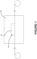
- FIGURE 1 illustrates the use of a metal detector 30 for use in the food industry. More specifically, a food item 10, such as a ready to eat meal, frozen food, etc., is passed through the metal detector 30 prior to shipping.
- the metal detector is typically in the form of a tunnel.
- Metal detectors 30 used in food scanning operations are oftentimes configured with a detection threshold for metal. In the event that a detectable mass of metal 40 is detected in excess of the set detection threshold, the food item 10 may be rejected, disposed of, or diverted to a separate production or inspection area for further investigation into the source of the metal detection. While this outcome is desirable in the event that the food product item 10 has metal contamination, false positive detections result in manufacturing/production delays, and the need for human intervention, neither of which are efficient or desirable.
- FIGURE 2 illustrates a side perspective view of a RFID device 100 containing a RFIF chip 110 and a conductive structure 120.
- the RFID device 100 is attached to a food product packaging 20 in accordance with the disclosed architecture, though it is also contemplated that RFID device 100 may be directly attachable to the food product item 10.
- Typical applications for attaching the RFID device 100 to food product item 10 or its associated packaging 20 include food product traceability, where the RFID device 100 is used in conjunction with a database for storing information, for example, to record exactly where and when the food product item 10 was produced, the identity of the source of the food product item 10, to associate the food product item 10 with its raw ingredients, to track the food product item 10 expiration or the "best by" dates, and any other trackable element that suits user need and/or preference.
- the food product packaging 20 may be microwavable or freezable depending on the requirements of the enclosed food product item 10.
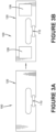
- FIGURE 3A illustrates a top view of RFID device 100, which contains an RFID chip 110 and conductive structure 120. More specifically, RFID chip 110 is electrically coupled to conductive structure 120. However, the mass of the metal of conductive structure 120 of RFID device 100 will likely trigger a false positive in a metal detector, such as metal detector 30 shown in FIGURE 1 .
- FIGURE 3B illustrates a top view of the RFID device 100 of FIGURE 3A but after removing portions of the conductive structure 120 of the RFID device in accordance with the disclosed architecture.
- the RFID device 100 of FIGURE 3 also contains a RFID chip 110 electrically coupled to a metallic conductive structure 120, but wherein a plurality of portions 128 of conductive structure 120 have been removed to reduce the overall metallic mass of the RFID device 100 without affecting its overall performance (i.e., to be successfully interrogated by an RFID reader (not shown) throughout the food product supply chain).
- the portions 128 of conductive structure 120 to be removed or hollowed out are chosen based on where the current flow through conductive structure 120 is relatively low compared to the rest of the conductive structure 120, and such that the result of the removal of portions 128 does not significantly affect performance of the RFID device 100. While this reduction in material is beneficial, other adjustments or other aspects of the RFID device 100 design may be required to provide optimal sensitivity.
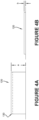
- the metal mass of the conductive structure 120 may also be reduced by reducing the thickness of either all or part of the conductive structure 120. More specifically, the conductive structure 120 illustrated in FIGURE 4A has an initial thickness (a). It is known to those of ordinary skill in the art that RF currents in the ultra-high frequency (UHF) frequency range in the region of 915MHz flow primarily on the surface of the conductor or antenna. Additionally, said currents reduce exponentially with the depth of the conductor. An expression of this current reducing effect is known as skin depth, and the conductive structure 120 of FIGURE 4A has a skin depth 130, as explained more fully below.
- UHF ultra-high frequency
- reduced thickness (b) is at least the thickness of skin depth 130. More specifically, skin depth 130 is a measure of the current density, and is defined as the distances from the outer edges of a conductor to the point at which the current density falls to 1/e of the value of the current at the surface of the conductor. For example, in a layer four times the skin depth from the surface of a conductor, approximately 98% of the current will flow in the conductor.
- a number of approaches may be taken to reduce the metallic mass of the conductive structure 120 to overcome the limitations of the prior art. For example, the selection of an RFID device with a relatively small antenna having a metal mass that is below the detection threshold of the metal detector and therefore, would not trigger a detection may be considered. However, RFID devices with reduced or relatively small RFID antenna sizes are commonly associated with lower and unacceptable RF performance.
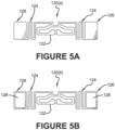
- FIGURE 5A illustrates a top view of an RFID device 100 having an initial conductive structure 120(a)
- FIGURE 5B illustrates a top view of the RFID device 100 having a modified conductive structure 120(b) in accordance with an embodiment of the invention.
- the conductive structure in an initial unmodified configuration 120(a) is a dipole type antenna, such as an AD238 RFID tag manufactured and sold by Avery Dennison, of Glendale, California.
- the example is used for exemplary purposes only, as many different initial unmodified RFID tags designs that may be used in relation to food production are contemplated herein.
- the conductive structure 120(a) contains a tuning loop 122, and a pair of dipole arms 124 each extending from the tuning loop 122 in generally opposite directions. More specifically, each of the dipole arms 124 may be meander-line type arms that each terminate in a load end 126. Each load end 126 is an area of top load for the conductive structure 120, which strengthens broadband.
- a standard detection threshold for a detectable mass 40 (as shown in FIGURE 1 ) for a metal detector 30 (also shown in FIGURE 1 ) of the type commonly used in the food production industry is a sphere approximately 1mm in diameter.
- the material used for the conductive structure 120 is aluminum and the volume of the detection threshold is approximately 0.52mm 3 . Therefore, the standard detection threshold in this example has a total metallic volume of 0.52mm 3 .
- the unmodified conductive structure 120(a) made with a starting thickness of 15 ⁇ m aluminum has a volume of approximately 8.6mm 3 , and an area of 573 mm 2 , which is well above the detection threshold and would likely result in a false positive by metal detector 30.
- reducing the conductive structure 120 from the starting thickness to a reduced thickness of 1 ⁇ m will reduce the volume of the conductive structure 120 to approximately 0.57mm 3 , which is much close to the detection threshold and does not change the overall conductive structure area.
- the reduced thickness of 1 ⁇ m is less than a skin depth 130 of the aluminum, so a reduction in RF performance should be expected.
- FIGURE 5B illustrates the result of a modification to the antenna design that results in a reduced overall metallic mass, while still maintaining an acceptable level of performance.
- the modified conductive structure 120(b) has a mass below the standard detection threshold of metal detector 30. More specifically, the overall conductive structure 120(b) ideally has a thickness greater than the skin depth 130 for the constructive material and frequency. In this example, the skin depth 130 for aluminum at a frequency of 915MHz is approximately 2.7 ⁇ m.
- the pair of load ends 126 are the areas of the conductive structure 120 in this example where the surface current flow is at its lowest. These are areas of top load, which strengthen broadband.
- a plurality of portions 128 are removed from, or hollowed out of, the pair of load ends 126. Removing these portions of the top load areas from the pair of load ends 126 reduces the volume of the conductive structure 120(b) in the present example to approximately 5.44mm 3 and an area of 363mm 2 , with relatively minimal impact on RFID performance with the correct design. Therefore, the hollowing out or removing of portions 128 has an effect of maintaining or improving broadband width, while decreasing overall antenna size requirements. Unfortunately, this volume is also still above the detection threshold for the metal detector, and will likely result in the generation of false positive readings by metal detector 30.
- the thickness of the conductive structure 120(b) to approximately 1 ⁇ m thick aluminum with an area of 363mm 2 , with the pair of load ends 126 having the plurality of hollowed out portions 128, further reduces the volume to approximately 0.36mm 3 , which is below the detection threshold of metal detector 30.
- a further reduction to a thickness of 500nm has the effect of reducing volume to approximately 0.18mm 3 .
- the conductive structure 120 may be manufactured by printing a conductive ink based on, for example, copper, silver, or graphene, cutting a metallic foil by a rotary cutting system, or a laser, or by etching, it may also be achieved at smaller thicknesses by vapor deposition.
- a RFID device 100 for use with food product items contains a RFID chip 110 and a conductive structure 120 electrically coupled to the RFID chip 110.
- the conductive structure 120 contains a tuning loop 122 and a pair of dipole arms 124. Each of the dipole arms 124 extend outwardly from the tuning loop 122 in generally opposite directions and terminate in a load end 126.
- Each load end 126 is an area of top load for the conductive structure 120, and the conductive structure 120 is manufactured to have a metallic mass below a standard detection threshold of a metal detector 30, of the type commonly used in the food production industry.
- the conductive structure 120 is configured so as to have an overall thickness that is ideally slightly greater than a skin depth 130 for the conductive structure material and frequency. Based on a standard detection threshold commonly used to scan food product items for foreign metallic objects, the conductive structure 120 will ideally have a total metallic volume of 0.52mm 3 or less. To achieve such a low volume, portions of the conductive structure 120 having lower or relatively low current flow, and that have minimal effect on RF performance, are removed or hollowed out, such as portions of the pair of load ends 126. More specifically, each load end 126 is hollowed out to create a plurality of openings or portions 128 within the load ends 126.
- the RFID device 100 described herein is manufactured with a reduced mass that is spread out throughout the conductive structure 120. As such, the RFID device 100 will not produce a high density "lump", and should produce a relatively diffuse image on x-ray.
- the relatively diffuse image will not block or obstruct detection of high-density materials, such as foreign metal objects, as the RFID device 100 will be relatively "transparent."
- Ideal materials for the conductive structure 120 for the x-ray application are materials with a relatively low density including, but not limited to, graphene (2.267 g/cm 3 ), aluminum (2.7 g/cm 3 ), and copper (8.96 g/cm 3 ). Therefore, it would be advantageous to construct the conductive structure 120 from a low density, high conductivity material such as, aluminum or graphene for x-ray applications. Metal detection is better related to conductivity. Whereas aluminum is a good choice, graphene, copper, and silver are better conductors.
- the RFID device 100 will ideally be "microwave safe.” More specifically, the RFID device described herein may also reduce or eliminate the sparking risks associated with using a microwave to cook a food product with an RFID device attached thereto by eliminating or removing, such as by hollowing out, a portion of the metal conductive structure of the RFID device.
- FIGURE 6 illustrates a method of reducing the metallic mass of a conductive structure 120 of RFID device 100. More specifically, the method 200 begins at step 202 by providing a conductive structure 120 having an initial area and volume just large enough to adequately perform RFID functions in accordance with a user's specifications. At step 204, a skin depth 130 may be calculated based on the conductive structure's material and frequency as described supra, and, at step 206, the method continues as an overall initial thickness of the conductive structure 120 is reduced in one of the manners described above to achieve the profile depicted in FIGURE 4B . Typically, the reduced thickness of the conductive structure 120 should not be less than the calculated skin depth 130 for the conductive structure's specific material and frequency.
- step 208 areas of reduced current flow along the conductive structure 120 that will have little to no impact on the performance of conductive structure 120 and RFID device 100 are identified.
- the specific areas of the conductive structure 120 where current flow is low are located on a pair of load ends 126 of the conductive structure 120. Therefore, in step 210, the portions 128 of the conductive structure 120 where current flow is low are hollowed out to reduce the overall metallic mass of conductive structure 120 and RFID device 100. Removing this metal mass reduced the overall area of the conductive structure 120 as much as possible without significantly affecting the performance of the RFID device 100.
- the methods described herein provide an optimal solution for a design of the conductive structure 120 that provides the required performance and that is suitable for use with a food product 10 or its packaging 20, and metal detector 30.
Landscapes
- Engineering & Computer Science (AREA)
- Computer Hardware Design (AREA)
- Microelectronics & Electronic Packaging (AREA)
- Physics & Mathematics (AREA)
- General Physics & Mathematics (AREA)
- Theoretical Computer Science (AREA)
- Computer Networks & Wireless Communication (AREA)
- Geophysics And Detection Of Objects (AREA)
Claims (9)
- Leitfähige Struktur (120b) zur Verwendung mit einer RFID-Vorrichtung (100), wobei die leitfähige Struktur (120b) beim Passieren eines Metalldetektors (30) mit einer standardmäßigen Detektionsschwelle eines gesamten Metallvolumens von 0,52 mm3 nicht detektierbar ist,wobei die leitfähige Struktur ein Paar Dipolarme (124) umfasst, die sich entgegengesetzt von einer Abstimmschleife (122) erstrecken, wobei jeder des Paars Dipolarme in einem Lastende (126) endet,dadurch gekennzeichnet, dass von jedem Lastende ein Abschnitt (128) entfernt ist, um ein hohles Lastende (126) zu bilden.
- Leitfähige Struktur (120b) nach Anspruch 1, wobei die standardmäßige Detektionsschwelle eine Metallkugel mit 1 mm Durchmesser ist.
- Leitfähige Struktur (120b) nach Anspruch 1 oder 2, wobei eine Dicke der leitfähigen Struktur durch Gasphasenabscheidung erzielt wird.
- Leitfähige Struktur (120b) nach Anspruch 1 oder 2, wobei die leitfähige Struktur (120) entweder durch Drucken einer leitfähigen Tinte oder durch Schneiden einer Folie hergestellt wird.
- RFID-Vorrichtung (100), die beim Passieren eines Metalldetektors (30) mit einer standardmäßigen Detektionsschwelle eines gesamten Metallvolumens von 0,52 mm3 nicht detektierbar ist, wobei die RFID-Vorrichtung Folgendes umfasst:einen RFID-Chip (110); undeine leitfähige Struktur (120b) gemäß einem vorhergehenden Anspruch, die elektrisch an den RFID-Chip gekoppelt ist.
- RFID-Vorrichtung (100) nach Anspruch 5, wobei die RFID-Vorrichtung (100) die Detektion von hochdichten Materialien beim Röntgen nicht blockiert.
- Verfahren (200) zum Reduzieren einer Metallmasse einer RFID-Vorrichtung (100), umfassend:Bereitstellen (202) einer leitfähigen Struktur (120) mit einem Paar Dipolarme (124), die sich entgegengesetzt von einer Abstimmschleife (122) erstrecken, wobei jeder des Paars Dipolarme in einem Lastende (126) endet;Reduzieren (206) einer Dicke der leitfähigen Struktur, um eine reduzierte Dicke zu erzielen; undEntfernen (210) eines Abschnitts (128) jedes der Lastenden (126) der leitfähigen Struktur (120), um hohle Lastenden (126) zu bilden,wobei ein Stromfluss des Abschnitts geringer ist als der Stromfluss eines zweiten Abschnitts (128) der leitfähigen Struktur.
- Verfahren nach Anspruch 7, ferner umfassend den Schritt Berechnen (204) einer Eindringtiefe (130) der leitfähigen Struktur.
- Verfahren nach Anspruch 7 oder 8, wobei die reduzierte Dicke nicht geringer ist als die Eindringtiefe (130) der leitfähigen Struktur (120).
Applications Claiming Priority (2)
| Application Number | Priority Date | Filing Date | Title |
|---|---|---|---|
| US201962954909P | 2019-12-30 | 2019-12-30 | |
| PCT/US2020/067115 WO2021138237A1 (en) | 2019-12-30 | 2020-12-28 | Metal detector resistant rfid tags |
Publications (2)
| Publication Number | Publication Date |
|---|---|
| EP4085381A1 EP4085381A1 (de) | 2022-11-09 |
| EP4085381B1 true EP4085381B1 (de) | 2025-03-19 |
Family
ID=74347698
Family Applications (1)
| Application Number | Title | Priority Date | Filing Date |
|---|---|---|---|
| EP20848743.9A Active EP4085381B1 (de) | 2019-12-30 | 2020-12-28 | Metalldetektorresistente rfid-etiketten |
Country Status (5)
| Country | Link |
|---|---|
| US (1) | US12282817B2 (de) |
| EP (1) | EP4085381B1 (de) |
| JP (1) | JP7624005B2 (de) |
| CN (1) | CN115087987B (de) |
| WO (1) | WO2021138237A1 (de) |
Families Citing this family (4)
| Publication number | Priority date | Publication date | Assignee | Title |
|---|---|---|---|---|
| BR112022014785A2 (pt) | 2020-01-27 | 2022-09-20 | Avery Dennison Retail Information Services Llc | Método para autenticar um item |
| US12380291B2 (en) | 2020-10-23 | 2025-08-05 | Avery Dennison Retail Information Services Llc | Systems containing multiple read zones and methods of use thereof |
| WO2023178287A1 (en) | 2022-03-16 | 2023-09-21 | Avery Dennison Retail Information Services, Llc | Methods for identifying an event of concern for an item in a supply chain |
| CN114970796B (zh) * | 2022-08-02 | 2022-11-18 | 三亚汉烯石墨烯技术研究所有限公司 | 可随微波炉加热的石墨烯膜rfid标签及其制备方法 |
Family Cites Families (166)
| Publication number | Priority date | Publication date | Assignee | Title |
|---|---|---|---|---|
| AU506612B2 (en) | 1976-10-08 | 1980-01-17 | Pillsbury Co., The | Microwave heating package |
| JPH08291914A (ja) | 1995-04-20 | 1996-11-05 | Fujitsu Ltd | 電子レンジ加熱制御方式 |
| USD383465S (en) | 1995-11-30 | 1997-09-09 | Hideki Okuchi | Auxiliary antenna for cellular phone |
| DE19654902C2 (de) | 1996-03-15 | 2000-02-03 | David Finn | Chipkarte |
| JP2000090637A (ja) | 1998-09-09 | 2000-03-31 | Sony Corp | カセットラベル、ビデオテープカセット及びicカード |
| JP2000163543A (ja) | 1998-11-27 | 2000-06-16 | Hitachi Ltd | 無線icカードおよびその製造方法 |
| US8052061B2 (en) | 2002-08-07 | 2011-11-08 | Vanguard Identification Systems, Inc. | Permanent RFID luggage tag with security features |
| DE19951561A1 (de) | 1999-10-27 | 2001-05-03 | Meto International Gmbh | Sicherungselement für die elektronischen Artikelsicherung |
| JP2001143043A (ja) | 1999-11-15 | 2001-05-25 | Sekisui Chem Co Ltd | 非接触式icカード及び非接触式icカードの継線方法 |
| JP2001317741A (ja) | 2000-02-28 | 2001-11-16 | Dainippon Printing Co Ltd | 食品の自動調理システムと電子レンジ |
| WO2001063189A1 (en) | 2000-02-28 | 2001-08-30 | Dai Nippon Printing Co., Ltd. | Automatic refrigerator system, refrigerator, automatic cooking system, and microwave oven |
| JP2001326526A (ja) | 2000-05-16 | 2001-11-22 | Mitsubishi Electric Corp | シールドアンテナコイル |
| JP2002049905A (ja) | 2000-08-03 | 2002-02-15 | Dainippon Printing Co Ltd | 非接触データキャリア付きパッケージと製品情報管理方法 |
| US6975834B1 (en) | 2000-10-03 | 2005-12-13 | Mineral Lassen Llc | Multi-band wireless communication device and method |
| JP2002150248A (ja) | 2000-11-14 | 2002-05-24 | Dainippon Printing Co Ltd | 衝撃感知センサ付きデータキャリア装置 |
| US6924688B1 (en) | 2000-11-28 | 2005-08-02 | Precision Dynamics Corporation | Rectifying charge storage device with antenna |
| WO2002099764A1 (en) | 2001-06-05 | 2002-12-12 | Motorola, Inc. | Capacitively powered data communication system with tag and circuit carrier apparatus for use therein |
| JP2003030612A (ja) | 2001-07-19 | 2003-01-31 | Oji Paper Co Ltd | Icチップ実装体 |
| JP2003087044A (ja) | 2001-09-12 | 2003-03-20 | Mitsubishi Materials Corp | Rfid用アンテナ及び該アンテナを備えたrfidシステム |
| US7214569B2 (en) | 2002-01-23 | 2007-05-08 | Alien Technology Corporation | Apparatus incorporating small-feature-size and large-feature-size components and method for making same |
| MXPA05001550A (es) | 2002-08-08 | 2005-10-05 | Neology Inc | Dispositivo de identificacion de frecuencias multiples. |
| US7224280B2 (en) | 2002-12-31 | 2007-05-29 | Avery Dennison Corporation | RFID device and method of forming |
| US11334728B2 (en) | 2003-03-03 | 2022-05-17 | Lone Star Scm Systems, Lp | Interrogator and interrogation system employing the same |
| US7652636B2 (en) | 2003-04-10 | 2010-01-26 | Avery Dennison Corporation | RFID devices having self-compensating antennas and conductive shields |
| US20040234653A1 (en) | 2003-05-22 | 2004-11-25 | Cogley Paul A. | Susceptor tray and mirowavable dough products |
| US20040238534A1 (en) | 2003-05-29 | 2004-12-02 | Mast Roy Lee | Package for microwave cooking |
| CN100583554C (zh) | 2003-08-29 | 2010-01-20 | 精工爱普生株式会社 | 环形天线装置 |
| JP4452583B2 (ja) | 2003-08-29 | 2010-04-21 | セイコーエプソン株式会社 | ループアンテナ装置 |
| JP4557653B2 (ja) | 2003-09-25 | 2010-10-06 | 株式会社フジシールインターナショナル | マイクロ波処理用包装体 |
| JP2005101987A (ja) | 2003-09-25 | 2005-04-14 | Matsushita Electric Works Ltd | 集積無線idタグ |
| US7471173B2 (en) | 2003-11-06 | 2008-12-30 | Murata Manufacturing Co., Ltd | Resonator, filter, nonreciprocal circuit device, and communication apparatus |
| US6999028B2 (en) | 2003-12-23 | 2006-02-14 | 3M Innovative Properties Company | Ultra high frequency radio frequency identification tag |
| JP2005216044A (ja) | 2004-01-30 | 2005-08-11 | Seiko Precision Inc | 非接触icカード及び非接触icカード用ホルダ |
| US7421245B2 (en) | 2004-02-20 | 2008-09-02 | 3M Innovative Properties Company | Field-shaping shielding for radio frequency identification (RFID) system |
| JP2005252853A (ja) | 2004-03-05 | 2005-09-15 | Fec Inc | Rf−id用アンテナ |
| US7057562B2 (en) * | 2004-03-11 | 2006-06-06 | Avery Dennison Corporation | RFID device with patterned antenna, and method of making |
| US20120062367A1 (en) | 2004-04-06 | 2012-03-15 | Vanguard Identification Systems, Inc. | Near field communication enabled permanent rfid luggage tag |
| US7948381B2 (en) | 2004-04-30 | 2011-05-24 | Binforma Group Limited Liability Company | Reversibly deactivating a radio frequency identification data tag |
| JP2005323019A (ja) | 2004-05-07 | 2005-11-17 | Pegasus Net Kk | Rfidタグ用ブースターアンテナ |
| WO2005112591A2 (en) | 2004-05-14 | 2005-12-01 | Wavezero, Inc. | Radiofrequency antennae and identification tags and methods of manufacturing radiofrequency antennae and radiofrequency identification tags |
| US7158033B2 (en) | 2004-09-01 | 2007-01-02 | Avery Dennison Corporation | RFID device with combined reactive coupler |
| JP3960329B2 (ja) | 2004-11-02 | 2007-08-15 | 松下電器産業株式会社 | 加熱調理器およびそのプログラム |
| WO2006048964A1 (ja) | 2004-11-02 | 2006-05-11 | Matsushita Electric Industrial Co., Ltd. | 加熱装置 |
| US7452748B1 (en) | 2004-11-08 | 2008-11-18 | Alien Technology Corporation | Strap assembly comprising functional block deposited therein and method of making same |
| US7545328B2 (en) | 2004-12-08 | 2009-06-09 | Electronics And Telecommunications Research Institute | Antenna using inductively coupled feeding method, RFID tag using the same and antenna impedance matching method thereof |
| KR20100021665A (ko) | 2004-12-14 | 2010-02-25 | 후지쯔 가부시끼가이샤 | 안테나 및 비접촉형 태그 |
| JP4281683B2 (ja) | 2004-12-16 | 2009-06-17 | 株式会社デンソー | Icタグの取付構造 |
| US7355516B2 (en) | 2004-12-23 | 2008-04-08 | Checkpoint Systems, Inc. | Method and apparatus for protecting culinary products |
| CN100587745C (zh) | 2004-12-23 | 2010-02-03 | 关卡系统股份有限公司 | 保护烹饪产品的方法与仪器 |
| GB2423366B (en) | 2005-02-16 | 2010-02-24 | Cintex Ltd | Metal detector |
| JP2007026145A (ja) | 2005-07-19 | 2007-02-01 | Dainippon Printing Co Ltd | 非接触型のデータキャリア装置 |
| JP2007086863A (ja) | 2005-09-20 | 2007-04-05 | Fuji Xerox Co Ltd | 非接触icタグ、非接触icタグを備えた部材のパッケージ及び非接触icタグを備えた部材を用いる装置 |
| KR100717881B1 (ko) | 2005-09-23 | 2007-05-14 | 한국전자통신연구원 | 모바일 rfⅰd 리더 및 그 제어 방법 |
| JP2007089054A (ja) | 2005-09-26 | 2007-04-05 | Nippon Telegr & Teleph Corp <Ntt> | Rfidタグのアンテナ |
| JP4761952B2 (ja) | 2005-12-14 | 2011-08-31 | 富士通株式会社 | Rfidタグ |
| USD553124S1 (en) | 2006-01-05 | 2007-10-16 | Novariant Inc. | Roof module |
| US7391325B2 (en) | 2006-01-13 | 2008-06-24 | Honeywell International Inc. | Multifunctional multichip system for wireless sensing |
| US8786510B2 (en) | 2006-01-24 | 2014-07-22 | Avery Dennison Corporation | Radio frequency (RF) antenna containing element and methods of making the same |
| EP1821241A3 (de) | 2006-02-15 | 2008-07-23 | Assa Abloy AB | Hybride kontaktlose Frequenztranspondereinheit, Modul und Verfahren zur Herstellung |
| USD546819S1 (en) | 2006-02-17 | 2007-07-17 | Impinj, Inc. | Radio frequency identification tag antenna assembly |
| JP4026080B2 (ja) | 2006-02-24 | 2007-12-26 | オムロン株式会社 | アンテナ、およびrfidタグ |
| JP5055478B2 (ja) | 2006-02-28 | 2012-10-24 | 凸版印刷株式会社 | Icタグ |
| US7646304B2 (en) | 2006-04-10 | 2010-01-12 | Checkpoint Systems, Inc. | Transfer tape strap process |
| JP2008040904A (ja) | 2006-08-08 | 2008-02-21 | Hitachi Ltd | Rfidタグおよびその読み取り方法 |
| EP1870834A1 (de) | 2006-06-20 | 2007-12-26 | Assa Abloy Identification Technology Group AB | Halterung für markierte Artikel und in einer derartigen Halterung untergebrachter Artikel |
| ES2444222T3 (es) | 2006-07-10 | 2014-02-24 | Goji Limited | Preparación de alimentos |
| US20080018473A1 (en) | 2006-07-18 | 2008-01-24 | 3M Innovative Properties Company | Electrostatic discharge protection for components of an rfid tag |
| KR101478810B1 (ko) | 2006-07-28 | 2015-01-02 | 가부시키가이샤 한도오따이 에네루기 켄큐쇼 | 축전 장치 |
| JP4874035B2 (ja) * | 2006-09-05 | 2012-02-08 | 均 北吉 | キャビティ付き薄型スロットアンテナ及びアンテナ給電方法並びにこれらを用いたrfidタグ装置 |
| US9607188B2 (en) | 2014-09-29 | 2017-03-28 | Rfmicron, Inc. | Radio frequency identification (RFID) tag(s) and sensor(s) |
| US20080122631A1 (en) | 2006-11-29 | 2008-05-29 | Intermec Ip Corp. | Multiple band / wide band radio frequency identification (rfid) tag, such as for use as a metal mount tag |
| US7535366B2 (en) | 2006-12-13 | 2009-05-19 | 3M Innovative Properties Company | Microwaveable radio frequency identification tags |
| MX2009007509A (es) | 2007-01-11 | 2009-07-21 | Lg Electronics Inc | Electrodomestico para cocinar, sistema de control para el dispositivo para cocinar y metodo para controlar el dispositivo para cocinar. |
| DE102007009947B4 (de) * | 2007-03-01 | 2016-11-24 | Techpointe S.A. | Steckerelement |
| US7965186B2 (en) | 2007-03-09 | 2011-06-21 | Corning Cable Systems, Llc | Passive RFID elements having visual indicators |
| CN100573564C (zh) | 2007-05-16 | 2009-12-23 | 上海华龙信息技术开发中心 | 双频段多协议射频识别设备系统 |
| CN104540317B (zh) | 2007-07-17 | 2018-11-02 | 株式会社村田制作所 | 印制布线基板 |
| CN101090175B (zh) | 2007-07-18 | 2013-07-10 | 北京邮电大学 | 电容和电感耦合的超高频rfid通用标签天线 |
| US7880614B2 (en) | 2007-09-26 | 2011-02-01 | Avery Dennison Corporation | RFID interposer with impedance matching |
| WO2009050662A1 (en) | 2007-10-19 | 2009-04-23 | Petratec International Ltd. | Rfid tag especially for use near conductive objects |
| GB2455779A (en) | 2007-12-21 | 2009-06-24 | Novalia Ltd | Reader and electronic tag with conductive tracks having narrow and wide sections |
| EP2722796B1 (de) | 2007-12-22 | 2016-05-11 | Baumer hhs GmbH | Verfahren zur Herstellung eines Druckproduktes mit RFID-Transponder |
| US7744005B2 (en) | 2008-01-16 | 2010-06-29 | Taiwan Name Plate Co., Ltd. | Induction card with a printed antenna |
| USD634738S1 (en) | 2008-01-30 | 2011-03-22 | Yfy Rfid Technologies Company Limited | RFID antenna |
| US8056814B2 (en) | 2008-02-27 | 2011-11-15 | Tagsys Sas | Combined EAS/RFID tag |
| EP2251934B1 (de) | 2008-03-03 | 2018-05-02 | Murata Manufacturing Co. Ltd. | Drahtlose integrierte schaltung und drahtloses kommunikationssystem |
| JP4518211B2 (ja) | 2008-03-03 | 2010-08-04 | 株式会社村田製作所 | 複合アンテナ |
| US8289165B2 (en) | 2008-06-11 | 2012-10-16 | Avery Dennison Corporation | RFID device with conductive loop shield |
| JPWO2009157081A1 (ja) | 2008-06-26 | 2011-12-01 | 富士通株式会社 | Rfidタグ |
| US20100000980A1 (en) | 2008-07-02 | 2010-01-07 | Bogdan Popescu | Induction Heating System with Versatile Inductive Cartridge |
| JP5094630B2 (ja) | 2008-08-11 | 2012-12-12 | 株式会社日立製作所 | Icタグ |
| US8228197B2 (en) | 2008-11-10 | 2012-07-24 | Pouch Pac Innovations, Llc | Flexible pouch with smart tags |
| US8174388B2 (en) | 2008-12-10 | 2012-05-08 | Sensormatic Electronics, LLC | Method and system for deactivation of combination EAS/RFID tags |
| CN102273012B (zh) | 2009-01-09 | 2013-11-20 | 株式会社村田制作所 | 无线ic器件及无线ic模块 |
| US9277601B2 (en) | 2009-02-26 | 2016-03-01 | International Business Machines Corporation | Operating an appliance based on cooking instructions embedded in an RFID product tag |
| JP5173896B2 (ja) | 2009-03-09 | 2013-04-03 | レンゴー株式会社 | Rfidタグ用ブースタアンテナ |
| US8286887B2 (en) | 2009-03-10 | 2012-10-16 | Wal-Mart Stores, Inc. | RFID tag sensors and methods |
| CN102422310B (zh) | 2009-03-10 | 2015-11-25 | 沃尔玛百货有限公司 | 通用rfid标签和制造方法 |
| JP5204032B2 (ja) | 2009-05-07 | 2013-06-05 | レンゴー株式会社 | Rfidタグ用ブースタアンテナ |
| US20150255994A1 (en) * | 2009-09-25 | 2015-09-10 | Witricity Corporation | Safety systems for wireless energy transfer in vehicle applications |
| JP2011100181A (ja) | 2009-11-04 | 2011-05-19 | Toppan Printing Co Ltd | 非接触icラベルとアンテナ内蔵被接着体 |
| US9368580B2 (en) | 2009-12-04 | 2016-06-14 | Sensor Electronic Technology, Inc. | Semiconductor material doping |
| US8833664B2 (en) | 2009-12-18 | 2014-09-16 | Yu Yung Choi | Enhanced performance and security RFID device |
| JP5464028B2 (ja) | 2010-04-19 | 2014-04-09 | 凸版印刷株式会社 | 偽変造防止用icラベル |
| JP2010231797A (ja) | 2010-05-13 | 2010-10-14 | Dainippon Printing Co Ltd | 非接触データキャリアを付したパッケージ |
| US8511569B1 (en) | 2010-11-02 | 2013-08-20 | Impinj, Inc. | RFID integrated circuit to strap mounting system |
| EP2580715B1 (de) * | 2010-06-14 | 2019-05-22 | Avery Dennison Corporation | Verfahren, system und vorrichtung zur herstellung von kurzfristigen rfid etiketten |
| JP2012035486A (ja) * | 2010-08-06 | 2012-02-23 | Toppan Printing Co Ltd | 非接触ic媒体及び非接触ic付き冊子 |
| WO2012020748A1 (ja) | 2010-08-10 | 2012-02-16 | 株式会社村田製作所 | プリント配線板及び無線通信システム |
| US9412061B2 (en) | 2010-08-13 | 2016-08-09 | Avery Dennison Corporation | Sensing radio frequency identification device with reactive strap attachment |
| US8646695B2 (en) | 2010-10-01 | 2014-02-11 | Disney Enterprises, Inc. | Combined HF and UHF RFID device |
| WO2012073113A2 (en) | 2010-11-29 | 2012-06-07 | Goji Ltd. | System, apparatus, and method for cooking using rf oven |
| EP2458530B1 (de) | 2010-11-30 | 2014-04-02 | Nxp B.V. | Mit einem Transponder markiertes Objekt, und Herstellungsverfahren |
| US9312594B2 (en) * | 2011-03-22 | 2016-04-12 | Intel Corporation | Lightweight cavity filter and radio subsystem structures |
| JP2013114513A (ja) | 2011-11-29 | 2013-06-10 | Nitta Ind Corp | 情報記憶媒体 |
| CN102521645B (zh) | 2011-12-29 | 2014-12-03 | 上海大学 | 宽频带抗金属射频识别标签及其金属表面专用安装结构 |
| US8628018B2 (en) | 2012-04-17 | 2014-01-14 | Nxp, B.V. | RFID circuit and method |
| WO2013156389A1 (en) | 2012-04-19 | 2013-10-24 | Smartrac Ip B.V. | Integrated loop structure for radio frequency identification |
| US20130293354A1 (en) | 2012-05-01 | 2013-11-07 | Jeevan Kumar Vemagiri | Discontinuous loop antennas suitable for radio-frequency identification (rfid) tags, and related components, systems, and methods |
| US20130313328A1 (en) | 2012-05-25 | 2013-11-28 | Omni-Id Cayman Limited | Shielded Cavity Backed Slot Decoupled RFID TAGS |
| JP6050961B2 (ja) | 2012-06-18 | 2016-12-21 | トッパン・フォームズ株式会社 | 非接触型データ受送信体 |
| USD697900S1 (en) | 2012-07-18 | 2014-01-21 | Kmw Inc. | Antenna radome |
| MX342900B (es) | 2012-07-19 | 2016-10-18 | 3M Innovative Properties Co | Etiqueta de blindaje electromagnetico. |
| KR102013419B1 (ko) | 2012-09-19 | 2019-08-23 | 한국전자통신연구원 | Rfid 통신 모드 선택 방법 및 근거리장 통신 및 원거리장 통신을 지원하는 rfid 장치 |
| BR112015032345B8 (pt) * | 2013-06-24 | 2022-08-30 | Avery Dennison Corp | Etiquetas de mercadoria usando um condutor de antena |
| US9378451B2 (en) | 2013-08-14 | 2016-06-28 | Avery Dennison Corporation | RFID labels with digitally printed indicia for matching merchandise appearance characteristics |
| US9275322B2 (en) | 2013-11-25 | 2016-03-01 | VivaLnk Limited (Cayman Islands) | Stretchable multi-layer wearable tag capable of wireless communications |
| JP2015162187A (ja) | 2014-02-28 | 2015-09-07 | 株式会社リコー | Rfidタグ、通信システム、及びrfidタグの使用方法 |
| USD716774S1 (en) | 2014-04-04 | 2014-11-04 | Avery Dennison Corporation | RFID inlay |
| US9874603B2 (en) | 2014-07-07 | 2018-01-23 | Avery Dennison Retail Information Services, Llc | System and method for capacitive coupling testing |
| JP2016033748A (ja) * | 2014-07-31 | 2016-03-10 | トッパン・フォームズ株式会社 | 非接触型データ受送信体 |
| USD763833S1 (en) | 2014-10-01 | 2016-08-16 | Ohio State Innovation Foundation | RFID tag |
| WO2016060938A2 (en) | 2014-10-08 | 2016-04-21 | RF Micron, Inc. | Radio frequency identification (rfid) moisture tag(s) and sensors with extended sensing via capillaries |
| CA2964959A1 (en) * | 2014-11-20 | 2016-05-26 | Total Safety U.S., Inc. | Safety control room |
| US9697455B2 (en) | 2014-12-26 | 2017-07-04 | Avery Dennison Retail Information Services, Llc | Using reactive coupling of a printed RFID chip on a strap to allow the printed material to be over-laminated with a barrier film against oxygen and moisture ingress |
| JP6445355B2 (ja) | 2015-03-09 | 2018-12-26 | デクセリアルズ株式会社 | アンテナ装置、及び電子機器 |
| USD880460S1 (en) | 2015-06-12 | 2020-04-07 | Avery Dennison Retail Information Services, Llc | Antenna |
| US10268945B1 (en) | 2015-06-30 | 2019-04-23 | Amazon Technologies, Inc. | RFID tags |
| US9418262B1 (en) | 2015-07-22 | 2016-08-16 | Vectare, Inc. | Method to differentiate radio frequency identification tags from other metal objects |
| WO2017094794A1 (ja) | 2015-12-02 | 2017-06-08 | 株式会社村田製作所 | 水分検出用rfidタグ付き衛生用品 |
| JP6350766B2 (ja) | 2016-01-18 | 2018-07-04 | 株式会社村田製作所 | アンテナ装置および電子機器 |
| USD795228S1 (en) | 2016-03-04 | 2017-08-22 | Airgain Incorporated | Antenna |
| US10311355B1 (en) | 2016-03-31 | 2019-06-04 | Amazon Technologies, Inc. | RFID tags |
| JP3206091U (ja) * | 2016-06-13 | 2016-09-01 | 株式会社マーク | 多機能携帯端末用の起動操作具 |
| EP3493738A1 (de) * | 2016-08-02 | 2019-06-12 | Koninklijke Philips N.V. | Detektion von metallartefakten in patientenaugen vor mrt-untersuchungen |
| US10640249B2 (en) * | 2016-09-09 | 2020-05-05 | The Procter & Gamble Company | Track system for creating finished products |
| KR102556536B1 (ko) | 2016-09-30 | 2023-07-17 | 삼성전자주식회사 | 조리 기기 및 조리 기기의 제어 방법 |
| USD812045S1 (en) | 2016-10-06 | 2018-03-06 | Avery Dennison Retail Information Services, Llc | Antenna |
| GB2554952A (en) * | 2016-10-17 | 2018-04-18 | Parkside Flexibles Europe Ltd | Electronic identifier for packaging |
| CN114781571B (zh) | 2016-12-29 | 2025-11-21 | 艾利丹尼森零售信息服务公司 | 用于结合至可微波食品包装中的具有屏蔽结构的rfid标签 |
| USD837769S1 (en) | 2017-05-22 | 2019-01-08 | Shenzhen Antop Technology Limited | Antenna |
| US10733495B2 (en) | 2017-08-30 | 2020-08-04 | Precision Dynamics Corporation | Wearable RFID device |
| CN207424902U (zh) | 2017-11-17 | 2018-05-29 | 厦门信达物联科技有限公司 | 一种应用于无人超市的电子标签 |
| FR3075483B1 (fr) * | 2017-12-20 | 2019-12-27 | Swissto12 Sa | Dispositif radiofrequence passif, et procede de fabrication |
| JP6976865B2 (ja) * | 2018-01-05 | 2021-12-08 | ニッタ株式会社 | Icタグ |
| CA3090886A1 (en) * | 2018-03-07 | 2019-09-12 | The Procter & Gamble Company | System and methods for simultaneously producing products using independently guided vehicles |
| JP2021522573A (ja) | 2018-04-20 | 2021-08-30 | アベリー・デニソン・リテイル・インフォメーション・サービシズ・リミテッド・ライアビリティ・カンパニーAvery Dennison Retail Information Services, Llc | 電子レンジ対応の食品包装に組み込むための遮蔽型rfidタグ |
| EP3814994A1 (de) | 2018-06-27 | 2021-05-05 | Avery Dennison Retail Information Services, LLC | Gegen feldemission tolerante rfid-tags, die an produkten zum steuern des garprozesses angebracht sind |
| CN109389203A (zh) | 2018-10-11 | 2019-02-26 | 江苏金羿先磁新材料科技有限公司 | 一种抗金属rfid标签频点偏移调整方法 |
| USD855039S1 (en) | 2018-10-26 | 2019-07-30 | Pvc Antenna Inc. | Antenna |
| GB2578457B (en) * | 2018-10-29 | 2021-01-13 | Siemens Healthcare Ltd | Anomaly detection and correlation system. |
| EP3879991A4 (de) * | 2018-11-16 | 2022-08-03 | The Whole Coffee Company LLC | Systeme und verfahren zur herstellung von biomaterialien in abwesenheit von luftsauerstoff |
| US11005184B2 (en) * | 2018-11-29 | 2021-05-11 | Samsung Electro-Mechanics Co., Ltd. | Antenna apparatus |
| CA3109850A1 (en) * | 2020-02-24 | 2021-08-24 | Jordan Belton | Golf flagstick device for determining a gimme putt |
| US11854402B2 (en) * | 2020-07-10 | 2023-12-26 | Here Global B.V. | Method, apparatus, and system for detecting lane departure events based on probe data and sensor data |
| US12469348B2 (en) * | 2021-04-16 | 2025-11-11 | Armatura Llc | Integrated metal detection access control security gate |
-
2020
- 2020-12-28 JP JP2022540898A patent/JP7624005B2/ja active Active
- 2020-12-28 US US17/758,109 patent/US12282817B2/en active Active
- 2020-12-28 EP EP20848743.9A patent/EP4085381B1/de active Active
- 2020-12-28 WO PCT/US2020/067115 patent/WO2021138237A1/en not_active Ceased
- 2020-12-28 CN CN202080096618.6A patent/CN115087987B/zh active Active
Also Published As
| Publication number | Publication date |
|---|---|
| JP2023509436A (ja) | 2023-03-08 |
| CN115087987A (zh) | 2022-09-20 |
| US12282817B2 (en) | 2025-04-22 |
| JP7624005B2 (ja) | 2025-01-29 |
| US20230043210A1 (en) | 2023-02-09 |
| EP4085381A1 (de) | 2022-11-09 |
| CN115087987B (zh) | 2025-05-16 |
| WO2021138237A1 (en) | 2021-07-08 |
Similar Documents
| Publication | Publication Date | Title |
|---|---|---|
| EP4085381B1 (de) | Metalldetektorresistente rfid-etiketten | |
| US9092709B2 (en) | RFID tag including environmentally sensitive materials | |
| US20230054118A1 (en) | Rfid tags designed to work on difficult substrates | |
| US10026035B2 (en) | RFID tag including a coating | |
| US8616459B2 (en) | Suspendable packages with radio frequency identification | |
| US20120092027A1 (en) | RFID Wetness Sensing Device | |
| WO2005022443A2 (en) | A radio frequency identification tag with tamper detection capability | |
| EP3350751B1 (de) | Rfid-etikett mit manipulationssicherer anordnung | |
| EP3238142B1 (de) | Verwendung von reaktiver kopplung eines gedruckten rfid-chips auf einem band zum überlaminieren des gedruckten materials mit einer sperrschicht gegen das eindringen von sauerstoff und feuchtigkeit | |
| US20200125915A1 (en) | Foil tag | |
| US10565411B2 (en) | Detection of seal integrity on products using RFID | |
| US12159521B2 (en) | Control of RFID devices for increased reliability and effectiveness in an RFID electronic article surveillance system |
Legal Events
| Date | Code | Title | Description |
|---|---|---|---|
| STAA | Information on the status of an ep patent application or granted ep patent |
Free format text: STATUS: UNKNOWN |
|
| STAA | Information on the status of an ep patent application or granted ep patent |
Free format text: STATUS: THE INTERNATIONAL PUBLICATION HAS BEEN MADE |
|
| PUAI | Public reference made under article 153(3) epc to a published international application that has entered the european phase |
Free format text: ORIGINAL CODE: 0009012 |
|
| STAA | Information on the status of an ep patent application or granted ep patent |
Free format text: STATUS: REQUEST FOR EXAMINATION WAS MADE |
|
| 17P | Request for examination filed |
Effective date: 20220629 |
|
| AK | Designated contracting states |
Kind code of ref document: A1 Designated state(s): AL AT BE BG CH CY CZ DE DK EE ES FI FR GB GR HR HU IE IS IT LI LT LU LV MC MK MT NL NO PL PT RO RS SE SI SK SM TR |
|
| DAV | Request for validation of the european patent (deleted) | ||
| DAX | Request for extension of the european patent (deleted) | ||
| STAA | Information on the status of an ep patent application or granted ep patent |
Free format text: STATUS: EXAMINATION IS IN PROGRESS |
|
| 17Q | First examination report despatched |
Effective date: 20240206 |
|
| GRAP | Despatch of communication of intention to grant a patent |
Free format text: ORIGINAL CODE: EPIDOSNIGR1 |
|
| STAA | Information on the status of an ep patent application or granted ep patent |
Free format text: STATUS: GRANT OF PATENT IS INTENDED |
|
| RIC1 | Information provided on ipc code assigned before grant |
Ipc: H01Q 9/28 20060101ALI20241008BHEP Ipc: H01Q 9/26 20060101ALI20241008BHEP Ipc: H01Q 1/22 20060101ALI20241008BHEP Ipc: G06K 19/077 20060101AFI20241008BHEP |
|
| INTG | Intention to grant announced |
Effective date: 20241017 |
|
| GRAS | Grant fee paid |
Free format text: ORIGINAL CODE: EPIDOSNIGR3 |
|
| GRAA | (expected) grant |
Free format text: ORIGINAL CODE: 0009210 |
|
| STAA | Information on the status of an ep patent application or granted ep patent |
Free format text: STATUS: THE PATENT HAS BEEN GRANTED |
|
| P01 | Opt-out of the competence of the unified patent court (upc) registered |
Free format text: CASE NUMBER: APP_2962/2025 Effective date: 20250117 |
|
| AK | Designated contracting states |
Kind code of ref document: B1 Designated state(s): AL AT BE BG CH CY CZ DE DK EE ES FI FR GB GR HR HU IE IS IT LI LT LU LV MC MK MT NL NO PL PT RO RS SE SI SK SM TR |
|
| REG | Reference to a national code |
Ref country code: GB Ref legal event code: FG4D |
|
| REG | Reference to a national code |
Ref country code: CH Ref legal event code: EP |
|
| REG | Reference to a national code |
Ref country code: DE Ref legal event code: R096 Ref document number: 602020048076 Country of ref document: DE |
|
| REG | Reference to a national code |
Ref country code: IE Ref legal event code: FG4D |
|
| PG25 | Lapsed in a contracting state [announced via postgrant information from national office to epo] |
Ref country code: RS Free format text: LAPSE BECAUSE OF FAILURE TO SUBMIT A TRANSLATION OF THE DESCRIPTION OR TO PAY THE FEE WITHIN THE PRESCRIBED TIME-LIMIT Effective date: 20250619 |
|
| PG25 | Lapsed in a contracting state [announced via postgrant information from national office to epo] |
Ref country code: FI Free format text: LAPSE BECAUSE OF FAILURE TO SUBMIT A TRANSLATION OF THE DESCRIPTION OR TO PAY THE FEE WITHIN THE PRESCRIBED TIME-LIMIT Effective date: 20250319 |
|
| REG | Reference to a national code |
Ref country code: LT Ref legal event code: MG9D |
|
| PG25 | Lapsed in a contracting state [announced via postgrant information from national office to epo] |
Ref country code: NO Free format text: LAPSE BECAUSE OF FAILURE TO SUBMIT A TRANSLATION OF THE DESCRIPTION OR TO PAY THE FEE WITHIN THE PRESCRIBED TIME-LIMIT Effective date: 20250619 |
|
| PG25 | Lapsed in a contracting state [announced via postgrant information from national office to epo] |
Ref country code: HR Free format text: LAPSE BECAUSE OF FAILURE TO SUBMIT A TRANSLATION OF THE DESCRIPTION OR TO PAY THE FEE WITHIN THE PRESCRIBED TIME-LIMIT Effective date: 20250319 |
|
| PG25 | Lapsed in a contracting state [announced via postgrant information from national office to epo] |
Ref country code: LV Free format text: LAPSE BECAUSE OF FAILURE TO SUBMIT A TRANSLATION OF THE DESCRIPTION OR TO PAY THE FEE WITHIN THE PRESCRIBED TIME-LIMIT Effective date: 20250319 |
|
| PG25 | Lapsed in a contracting state [announced via postgrant information from national office to epo] |
Ref country code: GR Free format text: LAPSE BECAUSE OF FAILURE TO SUBMIT A TRANSLATION OF THE DESCRIPTION OR TO PAY THE FEE WITHIN THE PRESCRIBED TIME-LIMIT Effective date: 20250620 Ref country code: BG Free format text: LAPSE BECAUSE OF FAILURE TO SUBMIT A TRANSLATION OF THE DESCRIPTION OR TO PAY THE FEE WITHIN THE PRESCRIBED TIME-LIMIT Effective date: 20250319 |
|
| REG | Reference to a national code |
Ref country code: NL Ref legal event code: MP Effective date: 20250319 |
|
| REG | Reference to a national code |
Ref country code: AT Ref legal event code: MK05 Ref document number: 1777558 Country of ref document: AT Kind code of ref document: T Effective date: 20250319 |
|
| PG25 | Lapsed in a contracting state [announced via postgrant information from national office to epo] |
Ref country code: NL Free format text: LAPSE BECAUSE OF FAILURE TO SUBMIT A TRANSLATION OF THE DESCRIPTION OR TO PAY THE FEE WITHIN THE PRESCRIBED TIME-LIMIT Effective date: 20250319 |
|
| PG25 | Lapsed in a contracting state [announced via postgrant information from national office to epo] |
Ref country code: SE Free format text: LAPSE BECAUSE OF FAILURE TO SUBMIT A TRANSLATION OF THE DESCRIPTION OR TO PAY THE FEE WITHIN THE PRESCRIBED TIME-LIMIT Effective date: 20250319 |
|
| PG25 | Lapsed in a contracting state [announced via postgrant information from national office to epo] |
Ref country code: SM Free format text: LAPSE BECAUSE OF FAILURE TO SUBMIT A TRANSLATION OF THE DESCRIPTION OR TO PAY THE FEE WITHIN THE PRESCRIBED TIME-LIMIT Effective date: 20250319 |
|
| PG25 | Lapsed in a contracting state [announced via postgrant information from national office to epo] |
Ref country code: ES Free format text: LAPSE BECAUSE OF FAILURE TO SUBMIT A TRANSLATION OF THE DESCRIPTION OR TO PAY THE FEE WITHIN THE PRESCRIBED TIME-LIMIT Effective date: 20250319 Ref country code: PT Free format text: LAPSE BECAUSE OF FAILURE TO SUBMIT A TRANSLATION OF THE DESCRIPTION OR TO PAY THE FEE WITHIN THE PRESCRIBED TIME-LIMIT Effective date: 20250721 |
|
| PG25 | Lapsed in a contracting state [announced via postgrant information from national office to epo] |
Ref country code: IT Free format text: LAPSE BECAUSE OF FAILURE TO SUBMIT A TRANSLATION OF THE DESCRIPTION OR TO PAY THE FEE WITHIN THE PRESCRIBED TIME-LIMIT Effective date: 20250319 Ref country code: PL Free format text: LAPSE BECAUSE OF FAILURE TO SUBMIT A TRANSLATION OF THE DESCRIPTION OR TO PAY THE FEE WITHIN THE PRESCRIBED TIME-LIMIT Effective date: 20250319 |
|
| PG25 | Lapsed in a contracting state [announced via postgrant information from national office to epo] |
Ref country code: AT Free format text: LAPSE BECAUSE OF FAILURE TO SUBMIT A TRANSLATION OF THE DESCRIPTION OR TO PAY THE FEE WITHIN THE PRESCRIBED TIME-LIMIT Effective date: 20250319 |
|
| PG25 | Lapsed in a contracting state [announced via postgrant information from national office to epo] |
Ref country code: CZ Free format text: LAPSE BECAUSE OF FAILURE TO SUBMIT A TRANSLATION OF THE DESCRIPTION OR TO PAY THE FEE WITHIN THE PRESCRIBED TIME-LIMIT Effective date: 20250319 Ref country code: EE Free format text: LAPSE BECAUSE OF FAILURE TO SUBMIT A TRANSLATION OF THE DESCRIPTION OR TO PAY THE FEE WITHIN THE PRESCRIBED TIME-LIMIT Effective date: 20250319 |
|
| PG25 | Lapsed in a contracting state [announced via postgrant information from national office to epo] |
Ref country code: RO Free format text: LAPSE BECAUSE OF FAILURE TO SUBMIT A TRANSLATION OF THE DESCRIPTION OR TO PAY THE FEE WITHIN THE PRESCRIBED TIME-LIMIT Effective date: 20250319 |
|
| PG25 | Lapsed in a contracting state [announced via postgrant information from national office to epo] |
Ref country code: SK Free format text: LAPSE BECAUSE OF FAILURE TO SUBMIT A TRANSLATION OF THE DESCRIPTION OR TO PAY THE FEE WITHIN THE PRESCRIBED TIME-LIMIT Effective date: 20250319 |
|
| PG25 | Lapsed in a contracting state [announced via postgrant information from national office to epo] |
Ref country code: IS Free format text: LAPSE BECAUSE OF FAILURE TO SUBMIT A TRANSLATION OF THE DESCRIPTION OR TO PAY THE FEE WITHIN THE PRESCRIBED TIME-LIMIT Effective date: 20250719 |
|
| REG | Reference to a national code |
Ref country code: DE Ref legal event code: R097 Ref document number: 602020048076 Country of ref document: DE |
|
| PGFP | Annual fee paid to national office [announced via postgrant information from national office to epo] |
Ref country code: DE Payment date: 20251118 Year of fee payment: 6 |
|
| PGFP | Annual fee paid to national office [announced via postgrant information from national office to epo] |
Ref country code: GB Payment date: 20251113 Year of fee payment: 6 |
|
| PG25 | Lapsed in a contracting state [announced via postgrant information from national office to epo] |
Ref country code: DK Free format text: LAPSE BECAUSE OF FAILURE TO SUBMIT A TRANSLATION OF THE DESCRIPTION OR TO PAY THE FEE WITHIN THE PRESCRIBED TIME-LIMIT Effective date: 20250319 |
|
| PGFP | Annual fee paid to national office [announced via postgrant information from national office to epo] |
Ref country code: FR Payment date: 20251111 Year of fee payment: 6 |
|
| PLBE | No opposition filed within time limit |
Free format text: ORIGINAL CODE: 0009261 |
|
| STAA | Information on the status of an ep patent application or granted ep patent |
Free format text: STATUS: NO OPPOSITION FILED WITHIN TIME LIMIT |
|
| REG | Reference to a national code |
Ref country code: CH Ref legal event code: L10 Free format text: ST27 STATUS EVENT CODE: U-0-0-L10-L00 (AS PROVIDED BY THE NATIONAL OFFICE) Effective date: 20260128 |
|
| 26N | No opposition filed |
Effective date: 20251222 |