EP4059663B1 - Schlagwerkzeug sowie verfahren und programm zur steuerung eines schlagwerkzeugs - Google Patents
Schlagwerkzeug sowie verfahren und programm zur steuerung eines schlagwerkzeugs Download PDFInfo
- Publication number
- EP4059663B1 EP4059663B1 EP20888091.4A EP20888091A EP4059663B1 EP 4059663 B1 EP4059663 B1 EP 4059663B1 EP 20888091 A EP20888091 A EP 20888091A EP 4059663 B1 EP4059663 B1 EP 4059663B1
- Authority
- EP
- European Patent Office
- Prior art keywords
- impact
- motor
- revolutions
- control unit
- tool
- Prior art date
- Legal status (The legal status is an assumption and is not a legal conclusion. Google has not performed a legal analysis and makes no representation as to the accuracy of the status listed.)
- Active
Links
Images


Classifications
-
- B—PERFORMING OPERATIONS; TRANSPORTING
- B25—HAND TOOLS; PORTABLE POWER-DRIVEN TOOLS; MANIPULATORS
- B25B—TOOLS OR BENCH DEVICES NOT OTHERWISE PROVIDED FOR, FOR FASTENING, CONNECTING, DISENGAGING OR HOLDING
- B25B21/00—Portable power-driven screw or nut setting or loosening tools; Attachments for drilling apparatus serving the same purpose
- B25B21/02—Portable power-driven screw or nut setting or loosening tools; Attachments for drilling apparatus serving the same purpose with means for imparting impact to screwdriver blade or nut socket
-
- B—PERFORMING OPERATIONS; TRANSPORTING
- B25—HAND TOOLS; PORTABLE POWER-DRIVEN TOOLS; MANIPULATORS
- B25B—TOOLS OR BENCH DEVICES NOT OTHERWISE PROVIDED FOR, FOR FASTENING, CONNECTING, DISENGAGING OR HOLDING
- B25B23/00—Details of, or accessories for, spanners, wrenches, screwdrivers
- B25B23/14—Arrangement of torque limiters or torque indicators in wrenches or screwdrivers
- B25B23/147—Arrangement of torque limiters or torque indicators in wrenches or screwdrivers specially adapted for electrically operated wrenches or screwdrivers
- B25B23/1475—Arrangement of torque limiters or torque indicators in wrenches or screwdrivers specially adapted for electrically operated wrenches or screwdrivers for impact wrenches or screwdrivers
-
- B—PERFORMING OPERATIONS; TRANSPORTING
- B25—HAND TOOLS; PORTABLE POWER-DRIVEN TOOLS; MANIPULATORS
- B25F—COMBINATION OR MULTI-PURPOSE TOOLS NOT OTHERWISE PROVIDED FOR; DETAILS OR COMPONENTS OF PORTABLE POWER-DRIVEN TOOLS NOT PARTICULARLY RELATED TO THE OPERATIONS PERFORMED AND NOT OTHERWISE PROVIDED FOR
- B25F5/00—Details or components of portable power-driven tools not particularly related to the operations performed and not otherwise provided for
Definitions
- the present disclosure generally relates to an impact tool, a method for controlling the impact tool, and a program. More particularly, the present disclosure relates to an impact tool including a motor to be subjected to vector control, a method for controlling the impact tool, and a program for performing the control method.
- Patent Literature 1 discloses an impact rotary tool (impact tool) including a motor, an impact mechanism, an output shaft, a control unit, trigger switch, and a motor driving unit.
- the impact mechanism includes a hammer and applies impacting force to the output shaft with the output of the motor, thus allowing the impact rotary tool to tighten a screw.
- the control unit gives a driving instruction according to a manipulative variable of the trigger switch to the motor driving unit.
- the motor driving unit regulates the voltage applied to the motor, thereby adjusting the number of revolutions of the motor.
- EP 3 473 383 A1 describes an electric working machine that includes a motor, a controller for controlling driving of the motor, a first setter, and a second setter.
- the first setter is operated for setting, as a control method for the motor, which is usable by the controller.
- the second setter is operated for setting, as a control method for the motor, which is usable by the controller, at least one of the control methods settable via the first setter.
- WO 2019/096615 A1 describes a method for detecting if a fastener is already tightened or not using a tightening tool with a pulse mechanism comprising the steps of placing the tightening tool on the fastener, accelerating the rotational parts of the tightening tool, limiting rotational speed of the rotational parts to a first rotational threshold value in revolutions per minute during an initial tightening phase, and detecting whether a pulse occurs during the initial tightening phase, said initial tightening phase being measured from a moment when the rotational parts are accelerated.
- Patent Literature 1 JP 2017-132021 A
- An object of the present disclosure is to provide an impact tool, a method for controlling the impact tool, and a program, all of which contribute to improving the work efficiency.
- An impact tool includes a motor, a control unit, an output shaft, a transmission mechanism, and an impact detection unit.
- the control unit performs vector control on the motor.
- the output shaft is to be coupled to a tip tool.
- the transmission mechanism transmits motive power of the motor to the output shaft.
- the transmission mechanism includes an impact mechanism.
- the impact mechanism performs an impact operation according to magnitude of torque applied to the output shaft.
- the impact mechanism applies impacting force to the output shaft while performing the impact operation.
- the impact detection unit determines, based on at least one of an excitation current to be supplied to the motor or a torque current to be supplied to the motor, whether or not the impact operation is being performed.
- the control unit places a limit on an increase in a number of revolutions of the motor before the impact detection unit detects the impact operation and removes the limit on the increase in the number of revolutions of the motor when the impact detection unit detects the impact operation.
- a method for controlling an impact tool is a method for controlling an impact tool including a motor, a control unit, an output shaft, and a transmission mechanism.
- the control unit performs vector control on the motor.
- the output shaft is to be coupled to a tip tool.
- the transmission mechanism transmits motive power of the motor to the output shaft.
- the transmission mechanism includes an impact mechanism.
- the impact mechanism performs an impact operation according to magnitude of torque applied to the output shaft.
- the impact mechanism applies impacting force to the output shaft while performing the impact operation.
- the method for controlling the impact tool includes impact detection processing, a first control, and a second control.
- the impact detection processing includes determining, based on at least one of an excitation current to be supplied to the motor or a torque current to be supplied to the motor, whether or not the impact operation is being performed.
- the first control includes placing a limit on an increase in a number of revolutions of the motor before the impact operation is detected in the impact detection processing.
- the second control includes removing the limit on the increase in the number of revolutions of the motor when the impact operation is detected in the impact detection processing.
- a program according to still another aspect of the present disclosure is designed to cause one or more processors to perform the method for controlling the impact tool described above.
- the impact tool 1 may be used as, for example, an impact screwdriver, a hammer drill, an impact drill, an impact drill-screwdriver, or an impact wrench.
- the impact tool 1 includes a motor 15, a control unit 4, an output shaft 21, a transmission mechanism 18, and an impact detection unit 49.
- the control unit 4 performs vector control on the motor 15.
- the output shaft 21 is to be coupled to a tip tool 28.
- the transmission mechanism 18 transmits motive power of the motor 15 to the output shaft 21.
- the transmission mechanism 18 includes an impact mechanism 17.
- the impact mechanism 17 performs an impact operation according to the magnitude of torque applied to the output shaft 21.
- the impact mechanism 17 applies impacting force to the output shaft 21 while performing the impact operation.
- the impact detection unit 49 determines, based on at least one of an excitation current (current measured value id1) to be supplied to the motor 15 or a torque current (current measured value iq1) to be supplied to the motor 15, whether or not the impact operation is being performed.
- the control unit 4 places a limit on an increase in the number N1 of revolutions (see FIG. 4 ) of the motor 15 before the impact detection unit 49 detects the impact operation and removes the limit on the increase in the number N1 of revolutions of the motor 15 when the impact detection unit 49 detects the impact operation.
- a limit is placed on an increase in the number N1 of revolutions of the motor 15 before the impact mechanism 17 starts performing the impact operation, thus reducing the chances of a work target such as a screw being tilted with respect to a workpiece such as a wall due to an excessive number N1 of revolutions and thereby improving the work efficiency.
- this also allows the number N1 of revolutions of the motor 15 to be increased once the impact mechanism 17 has started performing the impact operation, thus contributing to improving the work efficiency compared to a situation where the number N1 of revolutions cannot be increased.
- control unit 4 removes the limit on the increase in the number N1 of revolutions of the motor 15 after the impact operation has started to be performed, thus making the number N1 of revolutions controllable without depending on the user's skills.
- the motor 15 may be a brushless motor.
- the motor 15 according to this embodiment is a synchronous motor.
- the motor 15 may be a permanent magnet synchronous motor (PMSM).
- the motor 15 includes a rotor 13 having a permanent magnet 131 and a stator 14 having a coil 141.
- the rotor 13 includes a rotary shaft 16 which outputs rotational power. The rotor 13 rotates with respect to the stator 14 due to electromagnetic interaction between the coil 141 and the permanent magnet 131.
- the vector control is a type of motor control method in which a current supplied to the coil 141 of the motor 15 is broken down into a current component (excitation current) that generates a magnetic flux and a current component (torque current) that generates a torque (rotational power) and in which these current components are controlled independently of each other.
- At least one of the current measured values id1, iq1 is used for both purposes of performing the vector control and determining whether or not any impact operation is being performed. This allows a part of a circuit for performing the vector control and a part of a circuit for determining whether or not any impact operation is being performed to be shared. This contributes to reducing the areas and dimensions of circuits provided for the impact tool 1 and cutting down the cost required for the circuits. In addition, this also improves the accuracy of detection compared to, for example, a situation where a measured value of the output current of the power supply unit 32 of the impact tool 1 is used to determine whether or not any impact operation is being performed.
- the impact tool 1 includes a power supply unit 32, the motor 15, a motor rotation measuring unit 27, the transmission mechanism 18, the output shaft 21, a socket 23, and the tip tool 28.
- the impact tool 1 further includes a trigger switch 29 and the control unit 4.
- the control unit 4 includes the impact detection unit 49 for determining whether or not the impact mechanism 17 is performing any impact operation.
- the output shaft 21 is a part that rotates upon receiving the driving force transmitted from the motor 15 via the transmission mechanism 18.
- the socket 23 is fixed to the output shaft 21.
- the tip tool 28 is attached removably to the socket 23.
- the tip tool 28 rotates along with the output shaft 21.
- the impact tool 1 is designed to rotate the tip tool 28 by turning the output shaft 21 with the driving force applied by the motor 15. That is to say, the impact tool 1 is a tool for driving the tip tool 28 with the driving force applied by the motor 15.
- the tip tool 28 (also called a "bit”) may be a screwdriver bit or a drill bit, for example.
- One of various types of tip tools 28 is selected depending on the intended use and attached to the socket 23 for the intended use. Alternatively, the tip tool 28 may be directly attached to the output shaft 21.
- the impact tool 1 includes the socket 23, thus making the tip tool 28 replaceable depending on the intended use.
- the tip tool 28 does not have to be replaceable.
- the impact tool 1 may also be an impact tool designed to allow the use of only a particular type of tip tool 28, for example.
- the tip tool 28 is a screwdriver bit for tightening or loosening a fastening member 30 (screw). More specifically, the tip tool 28 is a plus screwdriver bit, of which a tip portion 280 is formed in a + (plus) shape. That is to say, the output shaft 21 holds the screwdriver bit for tightening or loosening a screw and rotates upon receiving motive power from the motor 15.
- the screw may be a bolt, a screw, or a nut, for example.
- the fastening member 30 is a wood screw.
- the fastening member 30 includes a head portion 301, a cylindrical portion 302, and a thread portion 303.
- the head portion 301 is connected to a first end of the cylindrical portion 302.
- the thread portion 303 is connected to a second end of the cylindrical portion 302.
- the head portion 301 has a screw hole (such as a plus (+) hole) that fits the tip tool 28.
- the thread portion 303 has a thread thereon.
- the tip tool 28 fits the fastening member 30. That is to say, the tip tool 28 is inserted into the screw hole on the head portion 301 of the fastening member 30. In this state, the tip tool 28 is caused to rotate by being driven by the motor 15, thereby turning the fastening member 30. In this manner, the fastening member 30 (wood screw) is screwed into a target member (such as a wall member) of screwing while forming a hole and a thread groove in the workpiece of screwing. That is to say, the tip tool 28 applies tightening (or loosening) force to the fastening member 30.
- a target member such as a wall member
- the power supply unit 32 supplies a current for driving the motor 15.
- the power supply unit 32 may be a battery pack, for example.
- the power supply unit 32 may include, for example, either a single secondary battery or a plurality of secondary batteries.
- the transmission mechanism 18 includes a planetary gear mechanism 25, a drive shaft 22, and the impact mechanism 17.
- the transmission mechanism 18 transmits the rotational power of the rotary shaft 16 of the motor 15 to the output shaft 21. More specifically, the transmission mechanism 18 regulates the rotational power of the rotary shaft 16 of the motor 15 and outputs the rotational power thus regulated as the rotational power of the output shaft 21.
- the rotary shaft 16 of the motor 15 is connected to the planetary gear mechanism 25.
- the drive shaft 22 is connected to the planetary gear mechanism 25 and the impact mechanism 17.
- the planetary gear mechanism 25 reduces the rotational power of the rotary shaft 16 of the motor 15 at a predetermined reduction ratio and outputs the rotational power thus reduced as the rotational power of the drive shaft 22.
- the impact mechanism 17 is coupled to the output shaft 21.
- the impact mechanism 17 transmits the rotational power (of the rotary shaft 16) of the motor 15, which has been received via the planetary gear mechanism 25 and the drive shaft 22, to the output shaft 21.
- the impact mechanism 17 also performs an impact operation of applying impacting force to the output shaft 21.
- the impact mechanism 17 includes a hammer 19, an anvil 20, and a spring 24.
- the hammer 19 is attached to the drive shaft 22 via a cam mechanism.
- the anvil 20 is in contact with, and rotates along with, the hammer 19.
- the spring 24 biases the hammer 19 toward the anvil 20.
- the anvil 20 is formed integrally with the output shaft 21. Alternatively, the anvil 20 may also be formed separately from, and be fixed to, the output shaft 21.
- the impact mechanism 17 causes the output shaft 21 to turn continuously with the rotational power of the motor 15. That is to say, in that case, the drive shaft 22 and the hammer 19 that are coupled to each other via the cam mechanism rotate along with each other and the hammer 19 and the anvil 20 also rotate with each other. Thus, the output shaft 21 formed integrally with the anvil 20 rotates.
- the impact mechanism 17 upon the application of a load with the predetermined magnitude or more to the output shaft 21, the impact mechanism 17 performs an impact operation.
- the impact mechanism 17 In performing the impact operation, the impact mechanism 17 generates impacting force by transforming the rotational power of the motor 15 into pulses of torque. That is to say, while the impact operation is being performed, the hammer 19 retreats by overcoming the biasing force applied by the spring 24 (i.e., goes away from the anvil 20) while being regulated by the cam mechanism between the drive shaft 22 and the hammer 19 itself.
- the hammer 19 starts advancing (i.e., toward the output shaft 21) while rotating, thereby applying impacting force to the anvil 20 in the rotational direction and causing the output shaft 21 to rotate. That is to say, the impact mechanism 17 applies rotational impact around the axis (output shaft 21) to the output shaft 21 via the anvil 20. While the impact mechanism 17 is performing the impact operation, the hammer 19 repeatedly performs the operation of applying impacting force to the anvil 20 in the rotational direction. Every time the hammer 19 advances and retreats, the impacting force is generated once.
- the trigger switch 29 is an operating member for accepting the operation of controlling the rotation of the motor 15.
- the motor 15 may be selectively activated (turned ON or OFF) by the operation of pulling the trigger switch 29.
- the rotational velocity of the motor 15 is adjustable depending on the manipulative variable of the operation of pulling the trigger switch 29 (i.e., depending on how deep the trigger switch 29 is pulled).
- the rotational velocity of the output shaft 21 is adjustable depending on the manipulative variable of the operation of pulling the trigger switch 29. The greater the manipulative variable is, the higher the rotational velocity of the motor 15 and the output shaft 21 becomes.
- the control unit 4 either starts or stops rotating the motor 15 and the output shaft 21, and controls the rotational velocity of the motor 15 and the output shaft 21, depending on the manipulative variable of the operation of pulling the trigger switch 29.
- the tip tool 28 is coupled to the output shaft 21 via the socket 23.
- the rotational velocity of the motor 15 and the output shaft 21 is controlled by operating the trigger switch 29, thereby controlling the rotational velocity of the tip tool 28.
- the motor rotation measuring unit 27 measures the rotational angle of the motor 15.
- a photoelectric encoder or a magnetic encoder may be adopted, for example.
- the impact tool 1 includes an inverter circuit section 51 (see FIG. 1 ).
- the inverter circuit section 51 supplies an electric current to the motor 15.
- the control unit 4 is used along with the inverter circuit section 51 to control the operation of the motor 15 by feedback control.
- the control unit 4 includes a computer system including one or more processors and a memory. At least some of the functions of the control unit 4 are performed by making the processor(s) of the computer system execute a program stored in the memory of the computer system.
- the program may be stored in the memory.
- the program may also be downloaded via a telecommunications line such as the Internet or distributed after having been stored in a non-transitory storage medium such as a memory card.
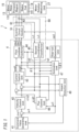
- the control unit 4 includes a command value generating unit 41, a velocity control unit 42, a current control unit 43, a first coordinate transformer 44, a second coordinate transformer 45, a flux control unit 46, an estimation unit 47, a step-out detection unit 48, and the impact detection unit 49.
- the impact tool 1 further includes a plurality of (e.g., two in the example illustrated in FIG. 1 ) current sensors 61, 62.
- Each of the plurality of current sensors 61, 62 includes, for example, a hall element current sensor or a shunt resistor element.
- the plurality of current sensors 61, 62 measure an electric current supplied from the power supply unit 32 (see FIG. 2 ) to the motor 15 via the inverter circuit section 51.
- three-phase currents namely, a U-phase current, a V-phase current, and a W-phase current
- the plurality of current sensors 61, 62 measure currents in at least two phases. In FIG. 1 , the current sensor 61 measures the U-phase current to output a current measured value i u 1 and the current sensor 62 measures the V-phase current to output a current measured value i v 1.
- the estimation unit 47 obtains a time derivative of the rotational angle ⁇ 1, measured by the motor rotation measuring unit 27, of the motor 15 to calculate an angular velocity ⁇ 1 of the motor 15 (i.e., the angular velocity of the rotary shaft 16).
- An acquisition unit 60 is made up of the two current sensors 61, 62 and the second coordinate transformer 45.
- the acquisition unit 60 acquires a d-axis current (excitation current) and a q-axis current (torque current), both of which are to be supplied to the motor 15. That is to say, the current measured value id1 of the d-axis current and the current measured value iq1 of the q-axis current are calculated by having two-phase currents measured by the two current sensors 61, 62 transformed by the second coordinate transformer 45.
- the second coordinate transformer 45 performs, based on the rotational angle ⁇ 1, measured by the motor rotation measuring unit 27, of the motor 15, coordinate transformation on the current measured values i u 1, i v 1 measured by the plurality of current sensors 61, 62, thereby calculating current measured values id1, iq1. That is to say, the second coordinate transformer 45 transforms the current measured values i u 1, i v 1, corresponding to currents in two out of three phases, into a current measured value id1 corresponding to a magnetic field component (d-axis current) and a current measured value iq1 corresponding to a torque component (q-axis current).
- the command value generating unit 41 generates a command value c ⁇ 1 for the angular velocity of the motor 15.
- the command value generating unit 41 may generate, for example, a command value c ⁇ 1 representing a manipulative variable that indicates how deep the trigger switch 29 (see FIG. 2 ) has been pulled. That is to say, as the manipulative variable increases, the command value generating unit 41 increases the command value c ⁇ 1 of the angular velocity accordingly.
- the velocity control unit 42 generates a command value ciq1 based on the difference between the command value c ⁇ 1 generated by the command value generating unit 41 and the angular velocity ⁇ 1 calculated by the estimation unit 47.
- the command value ciq1 is a command value specifying the magnitude of a torque current (q-axis current) of the motor 15.
- the velocity control unit 42 determines the command value ciq1 to reduce the difference between the command value c ⁇ 1 and the angular velocity ⁇ 1. More specifically, the velocity control unit 42 determines the command value ciq1 such that the difference becomes equal to or less than a predetermined first threshold value.
- the flux control unit 46 generates a command value cid1 based on the angular velocity ⁇ 1 calculated by the estimation unit 47, a command value cvql (to be described later) generated by the current control unit 43, and the current measured value iq1.
- the command value cid1 is a command value that specifies the magnitude of the excitation current (d-axis current) of the motor 15. That is to say, the control unit 4 controls the operation of the motor 15 to bring the excitation current (d-axis current) to be supplied to the coil 141 of the motor 15 closer toward the command value cid1.
- the command value cid1 generated by the flux control unit 46 may be, for example, a command value to set the magnitude of the excitation current at zero.
- the flux control unit 46 may generate the command value cid1 to set the magnitude of the excitation current at zero constantly or may generate a command value cid1 to set the magnitude of the excitation current at a value greater or smaller than zero only as needed.
- a negative excitation current i.e., a flux-weakening current
- the current control unit 43 generates a command value cvdl based on the difference between the command value cid1 generated by the flux control unit 46 and the current measured value id1 calculated by the second coordinate transformer 45.
- the command value cvdl is a command value that specifies the magnitude of d-axis voltage of the motor 15.
- the current control unit 43 determines the command value cvdl to reduce the difference between the command value cid1 and the current measured value id1. More specifically, the current control unit 43 determines the command value cvdl such that the difference becomes equal to or less than a predetermined second threshold value.
- the current control unit 43 also generates a command value cvql based on the difference between the command value ciq1 generated by the velocity control unit 42 and the current measured value iq1 calculated by the second coordinate transformer 45.
- the command value cvql is a command value that specifies the magnitude of q-axis voltage of the motor 15.
- the current control unit 43 generates the command value cvql to reduce the difference between the command value ciq1 and the current measured value iq1. More specifically, the current control unit 43 determines the command value cvql such that the difference becomes equal to or less than a predetermined third threshold value.
- the first coordinate transformer 44 performs coordinate transformation on the command values cvdl, cvq1 based on the rotational angle ⁇ 1, measured by the motor rotation measuring unit 27, of the motor 15 to calculate command values cv u 1, cv v 1, cv w 1. Specifically, the first coordinate transformer 44 transforms the command value cvdl for a magnetic field component (d-axis voltage) and the command value cvql for a torque component (q-axis voltage) into command values cv u 1, cv v 1, cv w 1 corresponding to voltages in three phases. Specifically, the command value cv u 1 corresponds to a U-phase voltage, the command value cv v 1 corresponds to a V-phase voltage, and the command value cv w 1 corresponds to a W-phase voltage.
- the control unit 4 controls the power to be supplied to the motor 15 by performing pulse width modulation (PWM) control on the inverter circuit section 51.
- PWM pulse width modulation
- the inverter circuit section 51 supplies voltages in three phases, corresponding to the command values cv u 1, cv v 1, cv w 1, respectively, to the motor 15.
- the motor 15 is driven with the power (voltages in three phases) supplied from the inverter circuit section 51, thus generating rotational power.
- control unit 4 controls the excitation current such that the excitation current flowing through the coil 141 of the motor 15 comes to have a magnitude corresponding to the command value cid1 generated by the flux control unit 46.
- control unit 4 also controls the angular velocity of the motor 15 such that the angular velocity of the motor 15 becomes an angular velocity corresponding to the command value c ⁇ 1 generated by the command value generating unit 41.
- the step-out detection unit 48 detects a step-out (loss of synchronism) of the motor 15 based on the current measured values id1, iq1 acquired from the second coordinate transformer 45 and the command values cvdl, cvql acquired from the current control unit 43. On detecting the step-out, the step-out detection unit 48 transmits a stop signal cs1 to the inverter circuit section 51, thus having the supply of power from the inverter circuit section 51 to the motor 15 stopped.
- the impact detection unit 49 determines whether or not the impact mechanism 17 is performing any impact operation. The impact detection unit 49 will be described in detail later.
- FIG. 3 shows an analysis model of the vector control.
- armature winding fixed axes for the U-, V-, and W-phases.
- a rotational coordinate system rotating at the same rotational velocity as a magnetic flux generated by the permanent magnet 131 provided for the rotor 13 of the motor 15 is taken into account.
- the direction of the magnetic flux generated actually by the permanent magnet 131 is defined by a d-axis and a coordinate axis corresponding to the control of the motor 15 by the control unit 4 and corresponding to the d-axis is defined by a ⁇ -axis.
- a q-axis is set at a phase leading by an electrical angle of 90 degrees with respect to the d-axis.
- a ⁇ -axis is set at a phase leading by an electrical angle of 90 degrees with respect to the ⁇ -axis.
- the dq axes have rotated and their rotational velocity is designated by ⁇ .
- the ⁇ axes have also rotated and their rotational velocity is designated by ⁇ e .
- ⁇ e in FIG. 3 corresponds with ⁇ 1 shown in FIG. 1 .
- the d-axis angle (phase) as viewed from the U-phase armature winding fixed axis is designated by ⁇ .
- the ⁇ -axis angle (phase) as viewed from the U-phase armature winding fixed axis is designated by ⁇ e .
- ⁇ e in FIG. 3 corresponds with ⁇ 1 shown in FIG. 1 .
- the angles designated by ⁇ and ⁇ e are angles as electrical angles and are generally called "rotor positions" or "magnetic pole positions.”
- the rotational velocities designated by ⁇ and ⁇ e are angular velocities represented by electrical angles.
- the control unit 4 performs the vector control such that ⁇ and ⁇ e agree with each other.
- the control unit 4 performs control to compensate for the difference thus caused between ⁇ and ⁇ e , and therefore, the current measured value id1 of the d-axis current comes to have a positive or negative value.
- the current measured value id1 of the d-axis current comes to have a positive value.
- the current measured value id1 comes to have a negative value.
- the impact mechanism 17 performs an impact operation according to the magnitude of torque applied to the output shaft 21.
- the impact detection unit 49 determines, based on at least one of a torque current to be supplied to the coil 141 of the motor 15 or an excitation current to be supplied to the coil 141 of the motor 15, whether or not the impact mechanism 17 is performing the impact operation. Next, it will be described with reference to FIGS. 4 and 5 how the impact detection unit 49 may determine whether or not the impact operation is being performed.
- N1 indicates the number of revolutions of the (rotor 13 of the) motor 15
- cN1 indicates the command value of the number of revolutions of the motor 15. That is to say, the command value cN1 is a value obtained by converting an angular velocity command value c ⁇ 1 of the motor 15 into the number of revolutions.
- the control unit 4 has, as mutually switchable operation modes, a first mode and a second mode.
- the first mode the control unit 4 places a limit on an increase in the number N1 of revolutions of the motor 15 before the impact detection unit 49 detects the impact operation.
- the control unit 4 removes the limit on the increase in the number N1 of revolutions of the motor 15.
- the control unit 4 keeps the limit on the increase in the number N1 of revolutions of the motor 15 removed.
- the impact detection unit 49 may determine, at least when the operation mode of the control unit 4 is the first mode, whether or not the impact mechanism 17 is performing any impact operation.
- the impact detection unit 49 is supposed to determine, irrespective of the operation mode of the control unit 4, whether or not the impact mechanism 17 is performing the impact operation.
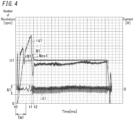
- FIG. 4 is a graph showing the results obtained when the operation mode of the control unit 4 is the second mode.
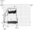
- FIG. 5 is a graph showing the results obtained when the operation mode of the control unit 4 is the first mode.
- the impact tool 1 includes a first user interface for accepting the user's operating command, for example.
- the first user interface may be, for example, a button, a slide switch, or a touchscreen panel.
- the control unit 4 switches the operation mode from the first mode to the second mode, and vice versa. For example, the user sets the operation mode of the control unit 4 at the first mode if the fastening member 30 is a wood screw and sets the operation mode of the control unit 4 at the second mode otherwise.
- the first user interface may display some marker representing a wood screw at a location where switch to the first mode is supposed to be made.
- markers include a character string such as "wood screw” or "wood screw mode” or an icon, picture, or photograph representing a wood screw.
- a marker may be provided on a mechanical button or a button displayed on the screen of the touchscreen panel for use to switch the operation mode to the first mode.
- the marker may also be provided beside the button.
- the marker may also be provided beside the location of a slide switch when the operation mode is the first mode.
- the impact detection unit 49 determines, based on at least one of a current measured value id1 of an excitation current or a current measured value iq1 of a torque current, whether or not any impact operation is being performed. In this embodiment, the impact detection unit 49 determines, based on both the current measured values id1, iq1, whether or not the impact operation is being performed.
- the impact detection unit 49 determines whether or not the following first condition is satisfied.
- the first condition is that the amplitude of the current measured value id1 be greater than a predetermined d-axis threshold value.
- the amplitude of the current measured value id1 is herein defined to be a half of the difference between the maximum and minimum values per unit time of the current measured value id1, for example.
- the impact detection unit 49 may determine, for example, every time a predetermined unit time passes, whether or not the first condition is satisfied.
- 4 and 5 is double the amplitude of the current measured value id1 which is defined by the current measured values id1 at respective points in time until the predetermined unit time (of a few milliseconds to several ten milliseconds, for example) passes since a certain point in time t1.
- the impact detection unit 49 determines, based on the amplitude of the current measured value id1 (of excitation current), whether or not the impact operation is being performed.
- the impact detection unit 49 determines whether or not the following second condition is satisfied.
- the second condition is that the magnitude of decrease per unit time (of several ten milliseconds, for example) in the current measured value iq1 be greater than a predetermined q-axis threshold value.
- the impact detection unit 49 may determine, for example, every time the predetermined time passes, whether or not the second condition is satisfied.
- the impact detection unit 49 determines, based on the magnitude of decrease per predetermined time in the current measured value iq1 (of a torque current), whether or not the impact operation is being performed.
- the impact detection unit 49 When finding the interval between a point in time when one of the first and second conditions is satisfied and a point in time when the other condition is satisfied equal to or less than a predetermined time threshold value, for example, the impact detection unit 49 outputs a result of detection indicating that the impact mechanism 17 is performing the impact operation. Otherwise, the impact detection unit 49 outputs a result of detection indicating that the impact mechanism 17 is not performing the impact operation.
- the load applied to the motor 15 increases and decreases incessantly.
- the magnitude of the increase or decrease in the load applied to the motor 15 rises, thus widening the difference between ⁇ and ⁇ e and causing an increase in the amplitude of the current measured value id1 of the excitation current.
- the load applied to the motor 15 falls while repeatedly increasing and decreasing, thus causing a decrease in the current measured value iq1 of the torque current.
- the impact detection unit 49 determines, by seeing based on the first and second conditions if any such change has occurred, whether or not the impact operation is being performed.
- Threshold values such as the d-axis threshold value and the q-axis threshold value may be stored in advance in, for example, a memory of a microcontroller serving as the control unit 4.
- the impact mechanism 17 starts performing the impact operation at a point in time t1.
- the amplitude of the current measured value id1 increases from the point in time t1 on.
- the current measured value iq1 decreases from the point in time t1 through a point in time t2.
- the impact detection unit 49 may detect, based on the first and second conditions, the impact operation.
- the operation mode of the control unit 4 is the second mode, and therefore, the control of the motor 15 by the control unit 4 is not affected, no matter whether the impact operation is detected or not.
- the impact mechanism 17 starts performing the impact operation at a point in time t1.
- the impact detection unit 49 outputs a result of detection indicating that the impact mechanism 17 is performing an impact operation.
- FIG. 5 is a graph showing the results of detection obtained when the operation mode of the control unit 4 is the first mode.
- the control unit 4 places a limit on the increase in the number N1 of revolutions of the motor 15 before the impact detection unit 49 detects the impact operation. Specifically, before the impact detection unit 49 detects the impact operation (i.e., from the point in time t0 through the point in time t2), the command value cN1 of the number N1 of revolutions of the motor 15 is equal to or less than an upper limit value U1. More specifically, when the user pulls the trigger switch 29 to the maximum depth, the command value cN1 becomes equal to the upper limit value U1.
- control unit 4 limits the number N1 of revolutions of the motor 15 to a predetermined upper limit value U1 or less before the impact detection unit 49 detects the impact operation. That is to say, at this time, the control unit 4 places a limit on the increase in the number N1 of revolutions of the motor 15.
- "limiting the number N1 of revolutions of the motor 15 to the predetermined upper limit value U1 or less” only requires that the number N1 of revolutions be equal to or less than the upper limit value U1 at least in a steady state.
- the number N1 of revolutions may temporarily exceed the upper limit value U1. For example, immediately after the number N1 of revolutions increasing has reached the upper limit value U1, the number N1 of revolutions may exceed the upper limit value U1 just temporarily as shown in FIG. 5 .
- the control unit 4 When the impact detection unit 49 detects the impact operation, the control unit 4 allows the number N1 of revolutions of the motor 15 to exceed the upper limit value U1 according to the manipulative variable of the trigger switch 29 (i.e., depending on how deep the trigger switch 29 has been pulled). Thus, the control unit 4 removes the limit on the increase in the number N1 of revolutions of the motor 15.
- the control unit 4 updates the state where the command value cN1 of the number N1 of revolutions of the motor 15 is limited to the upper limit value U1 or less into a state where the command value cN1 of the number N1 of revolutions of the motor 15 is limited to another limit value U2 or less, where the limit value U2 is greater than the upper limit value U1. In this manner, the control unit 4 lifts the restriction that the number N1 of revolutions of the motor 15 should not increase to exceed the upper limit value U1. In the state where the control unit 4 limits the command value cN1 to the limit value U2 or less, when the user pulls the trigger switch 29 to the maximum depth, the command value cN1 becomes equal to the limit value U2.
- the upper limit value U1 and the limit value U2 may be 15000 rpm and 25000 rpm, respectively.
- the upper limit value U1 and the limit value U2 may also be 21000 rpm and 24000 rpm, respectively.
- the number N1 of revolutions of the motor 15 may be kept lower, no matter how deep the trigger switch 29 is pulled, than in a situation where the command value cN1 of the number N1 of revolutions of the motor 15 is limited to the limit value U2 or less from the beginning. This makes it easier to stabilize the orientation of the fastening member 30 before the impact operation is started. If the fastening member 30 is a wood screw, for example, then the number N1 of revolutions may be kept relatively low until a tip part of the fastening member 30 is screwed to a certain depth or more into a target member (such as a wall member) into which the fastening member 30 should be screwed. Consequently, this makes it easier to stabilize the orientation of the fastening member 30.
- the "come out” phenomenon refers to an unintentional disengagement of the tip tool 28 out of the fastening member 30 while the motor 15 is running (rotating). That is to say, if the tip portion 280 of the tip tool 28 which has been inserted into the screw hole of the fastening member 30 has come out of the screw hole while the motor 15 is running (rotating), then the "come out” phenomenon has occurred.
- the first mode also enables having the work done in a shorter time since the impact operation has been started, compared to a situation where the command value cN1 of the number N1 of revolutions of the motor 15 is kept limited to the upper limit value U1 or less as shown in FIG. 4 .
- the command value cN1 of the number N1 of revolutions of the motor 15 is limited to the upper limit value U1 or less.
- the impact mechanism 17 starts performing the impact operation at a point in time t1.
- the impact detection unit 49 outputs a result of detection indicating that the impact mechanism 17 is performing the impact operation.
- the control unit 4 updates the state where the command value cN1 of the number N1 of revolutions of the motor 15 is limited to the upper limit value U1 or less into a state where the command value cN1 of the number N1 of revolutions of the motor 15 is limited to another limit value U2 or less. From this point in time t2 on, the command value cN1 will be kept limited to the limit value U2 or less until the motor 15 stops running.
- the fastening member 30 is screwed fully at the point in time t3.
- the user stops performing the operation of pulling the trigger switch 29.
- the command value cN1 decreases to 0 rpm, and therefore, the number N1 of revolutions goes 0 rpm. That is to say, the motor 15 stops running.
- any constituent element of this first variation having the same function as a counterpart of the embodiment described above, will be designated by the same reference numeral as that counterpart's, and description thereof will be omitted herein.
- the control unit 4 may not only lift the restriction that the command value cN1 of the number N1 of revolutions should be equal to or less than the upper limit value U1 but also increase the command value cN1 as well. That is to say, the control unit 4 increases the number N1 of revolutions indirectly by increasing the command value cN1.
- the control unit 4 may determine the command value cN1 provisionally depending on how deep the trigger switch 29 has been pulled and then increase the command value cN1. More specifically, the command value generating unit 41 of the control unit 4 increases the command value cN1 of the number N1 of revolutions substantially by increasing the command value c ⁇ 1 of the angular velocity.
- the control unit 4 may determine the number N1 of revolutions that has been increased based on the number N1 of revolutions that has not been increased yet. For example, when the impact detection unit 49 detects the impact operation, the control unit 4 may calculate a new command value cN1 by multiplying the command value cN1 at the point in time when the impact detection unit 49 detects the impact operation by a predetermined first value which is greater than one (e.g., 1.2). Alternatively, when the impact detection unit 49 detects the impact operation, the control unit 4 may calculate a new command value cN 1 by adding a predetermined second value (e.g., 2000 rpm) to the command value cN1 at the point in time when the impact detection unit 49 detects the impact operation. Nevertheless, the control unit 4 adjusts the predetermined first or second value as appropriate such that the command value cN1 becomes equal to or less than the limit value U2.
- a predetermined first value e.g. 2000 rpm
- the control unit 4 may set a setting as a new command value cN1.
- the setting is a value greater than the upper limit value U1 and equal to or less than the limit value U2. That is to say, when the impact detection unit 49 detects the impact operation, the control unit 4 may set the command value cN1 at a predetermined value, and thereby set the number N1 of revolutions at a predetermined number of revolutions.
- This first variation enables, even when the trigger switch 29 has been pulled relatively shallowly, increasing the command value cN1 and the number N1 of revolutions.
- any constituent element of this second variation having the same function as a counterpart of the embodiment described above, will be designated by the same reference numeral as that counterpart's, and description thereof will be omitted herein.
- the control unit 4 may control the number N1 of revolutions of the motor 15 toward a predetermined number of revolutions, no matter how deep the trigger switch 29 has been pulled. For example, in the interval between a point in time when the motor 15 started running in response to pulling of the trigger switch 29 and a point in time when the impact detection unit 49 detects the impact operation, the control unit 4 sets the command value cN1 of the number N1 of revolutions at a value equal to the upper limit value U1, thus reducing the chances of the number N1 of revolutions increasing to exceed the upper limit value U1. Also, when the impact detection unit 49 detects the impact operation, for example, the control unit 4 may set the command value cN1 at a value equal to the limit value U2. Thereafter, when the user stops pulling the trigger switch 29, the control unit 4 sets the command value cN1 at 0 rpm.
- This second variation makes the number N1 of revolutions of the motor 15 controllable without depending on the user's skill.
- the functions of the impact tool 1 may also be implemented as, for example, a method for controlling the impact tool 1, a (computer) program, or a non-transitory storage medium that stores the program thereon.
- a method for controlling an impact tool 1 includes impact detection processing, a first control, and a second control.
- the impact detection processing includes determining, based on at least one of an excitation current (current measured value id1) to be supplied to the motor 15 or a torque current (current measured value iq1) to be supplied to the motor 15, whether or not any impact operation is being performed.
- the first control includes placing a limit on an increase in the number N1 of revolutions of the motor 15 before the impact operation is detected in the impact detection processing.
- the second control includes removing the limit on the increase in the number N1 of revolutions of the motor 15 when the impact operation is detected in the impact detection processing.
- the control unit 4 first performs the first control to limit the command value cN1 of the number N1 of revolutions of the motor 15 to an upper limit value U1 or less (in Step ST1), thereby placing a limit on the increase in the number N1 of revolutions of the motor 15.
- the impact detection unit 49 determines whether or not the impact mechanism 17 is performing any impact operation (in Step ST2).
- Step ST2 When the impact detection unit 49 detects any impact operation (if the answer is YES in Step ST2), the control unit 4 updates the state where the command value cN1 of the number N1 of revolutions of the motor 15 is limited to the upper limit value U1 or less into a state where the command value cN1 of the number N1 of revolutions of the motor 15 is limited to a limit value U2 or less (in Step ST3). That is to say, the control unit 4 lifts the restriction that the number N1 of revolutions of the motor 15 should not increase to exceed the upper limit value U1.
- a program according to another aspect is designed to cause one or more processors to perform the method for controlling the impact tool 1 described above.
- the impact tool 1 includes a computer system.
- the computer system may include, as principal hardware components, a processor and a memory. Some of the functions of the impact tool 1 according to the present disclosure may be performed by making the processor execute a program stored in the memory of the computer system.
- the program may be stored in advance in the memory of the computer system. Alternatively, the program may also be downloaded through a telecommunications line or be distributed after having been recorded in some non-transitory storage medium such as a memory card, an optical disc, or a hard disk drive, any of which is readable for the computer system.
- the processor of the computer system may be made up of a single or a plurality of electronic circuits including a semiconductor integrated circuit (IC) or a large-scale integrated circuit (LSI).
- IC semiconductor integrated circuit
- LSI large-scale integrated circuit
- the "integrated circuit" such as an IC or an LSI is called by a different name depending on the degree of integration thereof.
- the integrated circuits include a system LSI, a very-large-scale integrated circuit (VLSI), and an ultra-large-scale integrated circuit (ULSI).
- a field-programmable gate array (FPGA) to be programmed after an LSI has been fabricated or a reconfigurable logic device allowing the connections or circuit sections inside of an LSI to be reconfigured may also be adopted as the processor.
- FPGA field-programmable gate array
- Those electronic circuits may be either integrated together on a single chip or distributed on multiple chips, whichever is appropriate. Those multiple chips may be aggregated together in a single device or distributed in multiple devices without limitation.
- the "computer system” includes a microcontroller including one or more processors and one or more memories.
- the microcontroller may also be implemented as a single or a plurality of electronic circuits including a semiconductor integrated circuit or a large-scale integrated circuit.
- the plurality of functions of the impact tool 1 are integrated together in a single housing. However, this is not an essential configuration for the impact tool 1. Alternatively, those constituent elements of the impact tool 1 may be distributed in multiple different housings. Still alternatively, at least some functions of the impact tool 1 (e.g., some functions of the impact detection unit 49) may be implemented as a cloud computing system as well.
- the motor 15 may be an AC motor or a DC motor, whichever is appropriate.
- the tip tool 28 does not have to be counted among the constituent elements of the impact tool 1.
- the tip tool 28 does not have to be a + (plus) screwdriver bit but may also be a - (minus) screwdriver bit. Alternatively, the tip tool 28 may even be a Torx ® bit or a wrench bit.
- the impact detection unit 49 may be provided separately from the control unit 4. That is to say, a constituent element performing the control unit's 4 function of performing the vector control on the motor 15 and a constituent element performing the impact detection unit's 49 function of determining whether or not any impact operation is being performed may be provided separately from each other.
- the motor rotation measuring unit 27 may be replaced with an acceleration sensor for measuring either the angular acceleration or circumferential acceleration of the rotary shaft 16 of the motor 15.
- the control unit 4 may have the function of changing at least one of the upper limit value U1 or the limit value U2.
- the impact tool 1 may include a second user interface for accepting the user's operating command, for example.
- the second user interface may be, for example, a button, a slide switch, or a touchscreen panel.
- the control unit 4 changes at least one of the upper limit value U1 or the limit value U2.
- the impact tool 1 may also include a reception unit for accepting a signal that has been input, for example.
- the reception unit receives the signal from an external device outside of the impact tool 1.
- the control unit 4 changes at least one of the upper limit value U1 or the limit value U2.
- the communication between the external device and the reception unit may be either wireless communication or wired communication, whichever is appropriate.
- at least some constituent elements may be used in common between the second user interface and the first user interface.
- the impact detection unit 49 may output a result of detection indicating that the impact mechanism 17 is performing the impact operation.
- the impact detection unit 49 may determine, based on only the first condition, whether or not the impact operation is being performed.
- the impact detection unit 49 may determine, based on only the second condition, whether or not the impact operation is being performed.
- the impact detection unit 49 may also use, as the second condition, a condition about the absolute value of the current measured value iq1.
- the second condition defined by the impact detection unit 49 may be that the absolute value of the current measured value iq1 (instantaneous value) be greater than a predetermined threshold value. Then, when finding the first condition satisfied after the second condition has been satisfied, the impact detection unit 49 may output a result of detection indicating that the impact mechanism 17 is performing the impact operation.
- the impact detection unit 49 may output a result of detection indicating that the impact mechanism 17 is performing the impact operation.
- the second condition defined by the impact detection unit 49 may also be that the absolute value of the current measured value iq1 have exceeded a predetermined threshold value and then the magnitude of decrease per predetermined time in the current measured value iq1 be greater than a predetermined q-axis threshold value. Then, when finding the interval between a point in time when one of the first and second conditions is satisfied and a point in time when the other condition is satisfied equal to or less than a predetermined time threshold value, for example, the impact detection unit 49 may output a result of detection indicating that the impact mechanism 17 is performing the impact operation.
- the impact detection unit 49 may determine, based on at least one of the absolute value of the current measured value iq1 (of torque current) or the magnitude of decrease per predetermined time in the current measured value iq1 (of torque current), whether or not the impact operation is being performed.
- the impact detection unit 49 may also determine, based on not only at least one of the current measured values id1, iq1 but also the number N1 of revolutions of the motor 15, whether or not the impact operation is being performed. That is to say, the impact detection unit 49 may determine, based on not only at least one of the first and second conditions but also the following third condition, whether or not the impact operation is being performed.
- the third condition is that the number N1 of revolutions of the motor 15 overshoot.
- the third condition is that an overshoot waveform Nos1 (see FIG. 4 ) be observed in the waveform representing the number N1 of revolutions of the motor 15.
- the "overshoot" means that a measured value is greater than a command value to a predetermined degree or more.
- the load applied to the motor 15 falls while repeatedly increasing and decreasing.
- the number N1 of revolutions temporarily increases to exceed the command value cN1.
- the impact detection unit 49 decides that the third condition should be satisfied.
- the impact detection unit 49 outputs a result of detection indicating that the impact mechanism 17 is performing the impact operation.
- the impact detection unit 49 may determine, based on the command value ciq1 instead of the current measured value iq1 of torque current, whether or not the impact operation is being performed. That is to say, in the exemplary embodiment and its variations described above, when a determination is made whether or not the impact operation is being performed, the current measured value iq1 may be replaced with the command value ciq1.
- An impact tool 1 includes a motor 15, a control unit 4, an output shaft 21, a transmission mechanism 18, and an impact detection unit 49.
- the control unit 4 performs vector control on the motor 15.
- the output shaft 21 is to be coupled to a tip tool 28.
- the transmission mechanism 18 transmits motive power of the motor 15 to the output shaft 21.
- the transmission mechanism 18 includes an impact mechanism 17.
- the impact mechanism 17 performs an impact operation according to magnitude of torque applied to the output shaft 21.
- the impact mechanism 17 applies impacting force to the output shaft 21 while performing the impact operation.
- the impact detection unit 49 determines, based on at least one of an excitation current (current measured value id1) to be supplied to the motor 15 or a torque current (current measured value iq1) to be supplied to the motor 15, whether or not the impact operation is being performed.
- the control unit 4 places a limit on an increase in a number N1 of revolutions of the motor 15 before the impact detection unit 49 detects the impact operation and removes the limit on the increase in the number N1 of revolutions of the motor 15 when the impact detection unit 49 detects the impact operation.
- a limit is placed on an increase in the number N1 of revolutions of the motor 15 before the impact mechanism 17 starts performing the impact operation, thus reducing the chances of a work target such as a screw being tilted with respect to a workpiece such a wall due to an excessive number N1 of revolutions and thereby improving the work efficiency.
- this also allows the number N1 of revolutions of the motor 15 to be increased once the impact mechanism 17 has started performing the impact operation, thus contributing to improving the work efficiency compared to a situation where the number N1 of revolutions cannot be increased.
- the impact detection unit 49 determines, based on an amplitude of the excitation current (current measured value id1), whether or not the impact operation is being performed.
- This configuration allows the impact detection unit 49 to determine whether or not any impact operation is being performed.
- the impact detection unit 49 determines, based on at least one of an absolute value of the torque current (current measured value iq 1) or magnitude of decrease per predetermined time in the torque current, whether or not the impact operation is being performed.
- This configuration allows the impact detection unit 49 to determine whether or not any impact operation is being performed.
- An impact tool 1 according to a fourth aspect, which may be implemented in conjunction with any one of the first to third aspects, further includes a trigger switch 29 to accept a user's operating command.
- the control unit 4 limits the number N1 of revolutions of the motor 15 to a predetermined upper limit value U1 or less before the impact detection unit 49 detects the impact operation and allows the number N1 of revolutions of the motor 15 to exceed the upper limit value U1 according to a manipulative variable of the trigger switch 29 when the impact detection unit 49 detects the impact operation.
- This configuration allows the number N1 of revolutions of the motor 15 to be increased in accordance with the user's operating command after the impact operation has started to be performed.
- control unit 4 increases the number N1 of revolutions of the motor 15 when the impact detection unit 49 detects the impact operation.
- This configuration allows the number N1 of revolutions of the motor 15 to be increased without the user's operation after the impact operation has started to be performed.
- control unit 4 sets the number N1 of revolutions of the motor 15 at a predetermined number of revolutions when the impact detection unit 49 detects the impact operation.
- This configuration enables setting the number N1 of revolutions of the motor 15 at an appropriate value without depending on the user's skill of operating the impact tool 1 after the impact operation has started to be performed.
- the control unit 4 has, as mutually switchable operation modes, a first mode and a second mode.
- the first mode the control unit 4 places the limit on the increase in the number N1 of revolutions of the motor 15 before the impact detection unit 49 detects the impact operation.
- the second mode the control unit 4 keeps the limit on the increase in the number N1 of revolutions of the motor 15 removed.
- This configuration enables selectively placing, depending on the necessity, a limit on the increase in the number N1 of revolutions of the motor 15.
- constituent elements according to the second to seventh aspects are not essential constituent elements for the impact tool 1 but may be omitted as appropriate.
- a method for controlling an impact tool 1 is a method for controlling an impact tool 1 including a motor 15, a control unit 4, an output shaft 21, and a transmission mechanism 18.
- the control unit 4 performs vector control on the motor 15.
- the output shaft 21 is to be coupled to a tip tool 28.
- the transmission mechanism 18 transmits motive power of the motor 15 to the output shaft 21.
- the transmission mechanism 18 includes an impact mechanism 17.
- the impact mechanism 17 performs an impact operation according to magnitude of torque applied to the output shaft 21.
- the impact mechanism 17 applies impacting force to the output shaft 21 while performing the impact operation.
- the method for controlling the impact tool 1 includes impact detection processing, a first control, and a second control.
- the impact detection processing includes determining, based on at least one of an excitation current current measured value id1) to be supplied to the motor 15 or a torque current (current measured value iq1) to be supplied to the motor 15, whether or not the impact operation is being performed.
- the first control includes placing a limit on an increase in a number N1 of revolutions of the motor 15 before the impact operation is detected in the impact detection processing.
- the second control includes removing the limit on the increase in the number N1 of revolutions of the motor 15 when the impact operation is detected in the impact detection processing.
- This method enables improving the work efficiency.
- a program according to a ninth aspect is designed to cause one or more processors to perform the method for controlling the impact tool 1 according to the eighth aspect.
- This program enables improving the work efficiency.
Landscapes
- Engineering & Computer Science (AREA)
- Mechanical Engineering (AREA)
- Control Of Electric Motors In General (AREA)
- Percussive Tools And Related Accessories (AREA)
- Details Of Spanners, Wrenches, And Screw Drivers And Accessories (AREA)
Claims (9)
- Ein Schlagwerkzeug (1), das Folgendes umfasst:einen Motor (15);eine Steuereinheit (4), die konfiguriert ist, um eine Vektorsteuerung am Motor (15) durchzuführen;eine Ausgangswelle (21), die konfiguriert ist, um mit einem Werkzeug an der Spitze bzw. Spitzenwerkzeug (tip tool) (28) gekoppelt zu werden;einen Übertragungsmechanismus (18), der einen Schlagmechanismus (17) beinhaltet und so konfiguriert ist, dass er eine Antriebskraft des Motors (15) auf die Ausgangswelle (21) überträgt, wobei der Schlagmechanismus (17) konfiguriert ist, um einen Schlagvorgang durchzuführen, bei dem entsprechend der Größe des auf die Ausgangswelle (21) aufgebrachten Drehmoments eine Schlagkraft auf die Ausgangswelle (21) aufgebracht wird; undeine Schlagerfassungseinheit (49), die konfiguriert ist, um auf der Grundlage von mindestens einem von einem dem Motor (15) zuzuführenden Erregerstrom (id1) oder einem dem Motor (15) zuzuführenden Drehmomentstrom (iq1) zu bestimmen, ob der Schlagvorgang durchgeführt wird oder nicht,wobei die Steuereinheit (4) so konfiguriert ist, dass sie einen Grenzwert für einen Anstieg einer Anzahl (N1) von Umdrehungen des Motors (15) festlegt, bevor die Schlagerfassungseinheit (49) den Schlagvorgang erfasst, und den Grenzwert für den Anstieg der Anzahl (N1) von Umdrehungen des Motors (15) aufhebt, wenn die Schlagerfassungseinheit (49) den Schlagvorgang erfasst.
- Das Schlagwerkzeug (1) nach Anspruch 1, wobei
die Schlagerfassungseinheit (49) konfiguriert ist, um auf der Grundlage einer Amplitude des Erregerstroms (id1) zu bestimmen, ob der Schlagvorgang durchgeführt wird oder nicht. - Das Schlagwerkzeug (1) nach Anspruch 1 oder 2, wobei
die Schlagerfassungseinheit (49) konfiguriert ist, um basierend auf mindestens einem von einem Absolutwert des Drehmomentstroms (iq1) oder der Größe der Abnahme des Drehmomentstroms (iq1) pro vorbestimmter Zeit zu bestimmen, ob der Schlagvorgang durchgeführt wird oder nicht. - Das Schlagwerkzeug (1) nach irgendeinem der Ansprüche 1 bis 3, umfassend einen Auslöseschalter (29), der konfiguriert ist, um einen Betriebsbefehl eines Benutzers anzunehmen, wobei
die Steuereinheit (4) so konfiguriert ist, dass sie die Anzahl (N1) der Umdrehungen des Motors (15) auf einen vorbestimmten oberen Grenzwert (U1) oder weniger begrenzt, bevor die Schlagerfassungseinheit (49) den Schlagvorgang erkennt, und zulässt, dass die Anzahl (N1) der Umdrehungen des Motors (15) den oberen Grenzwert (U1) entsprechend einer Stellgröße des Auslöseschalters (29) überschreitet, wenn die Schlagerfassungseinheit (49) den Schlagvorgang erkennt. - Das Schlagwerkzeug (1) nach irgendeinem der Ansprüche von 1 bis 4, wobei
die Steuereinheit (4) so konfiguriert ist, dass sie die Anzahl (N1) der Umdrehungen des Motors (15) erhöht, wenn die Schlagerfassungseinheit (49) den Schlagvorgang erkennt. - Das Schlagwerkzeug (1) nach Anspruch 5, wobei
die Steuereinheit (4) so konfiguriert ist, dass sie die Anzahl (N1) der Umdrehungen des Motors (15) auf eine vorbestimmte Anzahl von Umdrehungen festlegt, wenn die Schlagerfassungseinheit (49) den Schlagvorgang erkennt. - Das Schlagwerkzeug (1) nach irgendeinem der Ansprüche von 1 bis 6, wobei
die Steuereinheit (4) als untereinander umschaltbare Betriebsmodi einen ersten Modus aufweist, in dem die Steuereinheit (4) die Erhöhung der Anzahl (N1) der Umdrehungen des Motors (15) begrenzt, bevor die Schlagerfassungseinheit (49) den Schlagvorgang erkennt, und einen zweiten Modus, in dem die Steuereinheit (4) die Begrenzung aufhebt. - Ein Verfahren zur Steuerung eines Schlagwerkzeugs (1), wobei das Schlagwerkzeug (1) Folgendes beinhaltet:einen Motor (15);eine Steuereinheit (4), die konfiguriert ist, um eine Vektorsteuerung am Motor (15) durchzuführen;eine Ausgangswelle (21), die konfiguriert ist, um mit einem Werkzeug an der Spitze bzw. Spitzenwerkzeug (tip tool) (28) gekoppelt zu werden;einen Übertragungsmechanismus (18), der einen Schlagmechanismus (17) beinhaltet und so konfiguriert ist, dass er eine Antriebskraft des Motors (15) auf die Ausgangswelle (21) überträgt, wobei der Schlagmechanismus (17) konfiguriert ist, um einen Schlagvorgang durchzuführen, bei dem entsprechend der Größe des auf die Ausgangswelle (21) aufgebrachten Drehmoments eine Schlagkraft auf die Ausgangswelle (21) aufgebracht wird; undwobei das Verfahren Folgendes beinhaltet:eine Schlagerfassungs-Verarbeitung, die auf der Grundlage von mindestens einem von einem dem Motor (15) zuzuführenden Erregerstrom (id1) oder einem dem Motor (15) zuzuführenden Drehmomentstrom (iq1), das Bestimmen beinhaltet, ob der Schlagvorgang durchgeführt wird oder nicht,eine erste Steuerung, die das Festlegen eines Grenzwerts für die Erhöhung einer Anzahl (N1) von Umdrehungen des Motors (15) beinhaltet, bevor der Schlagvorgang in der Schlagerfassungs-Verarbeitung erkannt wird; undeine zweite Steuerung, die das Aufheben des Grenzwerts für die Erhöhung der Anzahl (N1) der Umdrehungen des Motors (15) beinhaltet, wenn der Schlagvorgang in der Schlagerfassungs-Verarbeitung erfasst wird.
- Ein Computerprogramm, das Anweisungen umfasst, die, wenn das Programm von einem Computer ausgeführt wird, den Computer veranlassen, das Verfahren zur Steuerung des Schlagwerkzeugs (1) gemäß Anspruch 8 durchzuführen.
Applications Claiming Priority (2)
| Application Number | Priority Date | Filing Date | Title |
|---|---|---|---|
| JP2019207501A JP7178591B2 (ja) | 2019-11-15 | 2019-11-15 | インパクト工具、インパクト工具の制御方法及びプログラム |
| PCT/JP2020/038840 WO2021095427A1 (ja) | 2019-11-15 | 2020-10-14 | インパクト工具、インパクト工具の制御方法及びプログラム |
Publications (3)
| Publication Number | Publication Date |
|---|---|
| EP4059663A1 EP4059663A1 (de) | 2022-09-21 |
| EP4059663A4 EP4059663A4 (de) | 2023-01-11 |
| EP4059663B1 true EP4059663B1 (de) | 2024-12-04 |
Family
ID=75911960
Family Applications (1)
| Application Number | Title | Priority Date | Filing Date |
|---|---|---|---|
| EP20888091.4A Active EP4059663B1 (de) | 2019-11-15 | 2020-10-14 | Schlagwerkzeug sowie verfahren und programm zur steuerung eines schlagwerkzeugs |
Country Status (4)
| Country | Link |
|---|---|
| US (1) | US11958173B2 (de) |
| EP (1) | EP4059663B1 (de) |
| JP (1) | JP7178591B2 (de) |
| WO (1) | WO2021095427A1 (de) |
Families Citing this family (3)
| Publication number | Priority date | Publication date | Assignee | Title |
|---|---|---|---|---|
| JP7281744B2 (ja) * | 2019-11-22 | 2023-05-26 | パナソニックIpマネジメント株式会社 | インパクト工具、インパクト工具の制御方法及びプログラム |
| DE102023200523A1 (de) * | 2023-01-24 | 2024-07-25 | Robert Bosch Gesellschaft mit beschränkter Haftung | Verfahren zum Betrieb einer Handwerkzeugmaschine |
| CN120916866A (zh) * | 2023-03-14 | 2025-11-07 | 艾沛克斯品牌公司 | 冲击式驱动器扭矩控制 |
Family Cites Families (102)
| Publication number | Priority date | Publication date | Assignee | Title |
|---|---|---|---|---|
| US3643749A (en) * | 1970-07-14 | 1972-02-22 | Ingersoll Rand Co | Signal inhibitor for impact wrench |
| JPS5637867Y2 (de) * | 1973-08-04 | 1981-09-04 | ||
| FI55892C (fi) * | 1974-03-18 | 1979-10-10 | Tampella Oy Ab | Hydraulisk borrmaskin i synnerhet bergborrningsmaskin |
| US4023626A (en) * | 1975-03-17 | 1977-05-17 | Oy Tampella Ab | Self-adaptive hydraulic rock drill |
| GB1572349A (en) * | 1976-05-21 | 1980-07-30 | Bsp Int Foundation | Drop hammers |
| US5154242A (en) * | 1990-08-28 | 1992-10-13 | Matsushita Electric Works, Ltd. | Power tools with multi-stage tightening torque control |
| JP2831195B2 (ja) * | 1992-03-25 | 1998-12-02 | 富士電機株式会社 | 半導体加速度センサ |
| JP3506450B2 (ja) * | 1992-12-18 | 2004-03-15 | 松下電器産業株式会社 | ねじ締め装置、およびねじ締め方法 |
| US5544710A (en) * | 1994-06-20 | 1996-08-13 | Chicago Pneumatic Tool Company | Pulse tool |
| JP3295596B2 (ja) * | 1996-05-31 | 2002-06-24 | 日東工器株式会社 | 油圧駆動工具制御装置 |
| JP3062655B2 (ja) | 1997-06-02 | 2000-07-12 | 株式会社ワコー技研 | ねじ締め装置 |
| EP1208946B1 (de) * | 1999-03-16 | 2006-02-01 | Kuken Co. Ltd | Verfahren zum ermitteln des schraubendrehwinkels von handdrehimpulsschraubern, verfahren zum feststellen von handvibratoren,verfahren zur auswertung vom anziehen und überwachungsverfahren eines angetriebenen handwerkzeugs zum lösen von schrauben |
| JP2001205575A (ja) * | 2000-01-28 | 2001-07-31 | Nitto Kohki Co Ltd | トルク制御式インパクトレンチ |
| DE10123397A1 (de) * | 2001-05-14 | 2002-11-28 | Wacker Werke Kg | Schlag- und/oder Bohrhammer mit einer zum Freischlagen festgeklemmter Gegenstände geeigneten Schlagvorrichtung |
| JP2005524540A (ja) * | 2002-05-09 | 2005-08-18 | スナップ − オン インコーポレイテッド | 空気の自動遮断 |
| JP2005118910A (ja) * | 2003-10-14 | 2005-05-12 | Matsushita Electric Works Ltd | インパクト回転工具 |
| JP2006214743A (ja) * | 2005-02-01 | 2006-08-17 | Matsushita Electric Works Ltd | 半導体加速度センサ |
| JP4211744B2 (ja) * | 2005-02-23 | 2009-01-21 | パナソニック電工株式会社 | インパクト締付け工具 |
| JP4400519B2 (ja) * | 2005-06-30 | 2010-01-20 | パナソニック電工株式会社 | インパクト回転工具 |
| US7227330B2 (en) | 2005-07-14 | 2007-06-05 | Yaskawa Electric America, Inc. | Overvoltage suppression technique for variable frequency drives operating reciprocating loads |
| US7487844B2 (en) * | 2005-11-04 | 2009-02-10 | Robert Bosch Gmbh | Drill with solid state speed control |
| US8698447B2 (en) * | 2007-09-14 | 2014-04-15 | The Powerwise Group, Inc. | Energy saving system and method for devices with rotating or reciprocating masses |
| TW200950306A (en) * | 2008-06-10 | 2009-12-01 | Mobiletron Electronics Co Ltd | Electric motor resistance torque control and battery discharging protection circuit |
| JP5405157B2 (ja) * | 2009-03-10 | 2014-02-05 | 株式会社マキタ | 回転打撃工具 |
| CN102481686B (zh) * | 2009-07-29 | 2015-10-14 | 日立工机株式会社 | 冲击工具 |
| WO2011013853A2 (en) * | 2009-07-29 | 2011-02-03 | Hitachi Koki Co., Ltd. | Impact tool |
| JP5537122B2 (ja) * | 2009-11-02 | 2014-07-02 | 株式会社マキタ | 電動工具 |
| JP5600955B2 (ja) * | 2010-02-11 | 2014-10-08 | 日立工機株式会社 | インパクト工具 |
| JP5483089B2 (ja) * | 2010-03-11 | 2014-05-07 | 日立工機株式会社 | インパクト工具 |
| JP5464434B2 (ja) * | 2010-03-31 | 2014-04-09 | 日立工機株式会社 | 電動工具 |
| JP5464014B2 (ja) * | 2010-03-31 | 2014-04-09 | 日立工機株式会社 | 電動工具 |
| CN102770248B (zh) * | 2010-03-31 | 2015-11-25 | 日立工机株式会社 | 电动工具 |
| JP5486435B2 (ja) * | 2010-08-17 | 2014-05-07 | パナソニック株式会社 | インパクト回転工具 |
| JP2012076160A (ja) * | 2010-09-30 | 2012-04-19 | Hitachi Koki Co Ltd | 電動工具 |
| CN103009349A (zh) * | 2010-11-30 | 2013-04-03 | 日立工机株式会社 | 冲击工具 |
| JP2012199143A (ja) * | 2011-03-22 | 2012-10-18 | Panasonic Corp | 電磁開閉装置 |
| JP5796741B2 (ja) * | 2011-05-19 | 2015-10-21 | 日立工機株式会社 | 電動工具 |
| JP2013022681A (ja) * | 2011-07-21 | 2013-02-04 | Hitachi Koki Co Ltd | 電動工具 |
| JP5755988B2 (ja) * | 2011-09-30 | 2015-07-29 | 株式会社マキタ | 電動工具 |
| JP5784473B2 (ja) * | 2011-11-30 | 2015-09-24 | 株式会社マキタ | 回転打撃工具 |
| JP2013146846A (ja) * | 2012-01-23 | 2013-08-01 | Max Co Ltd | 回転工具 |
| JP5935983B2 (ja) * | 2012-03-29 | 2016-06-15 | 日立工機株式会社 | 電動工具 |
| JP5896143B2 (ja) * | 2012-03-29 | 2016-03-30 | 日立工機株式会社 | 電動工具 |
| JP5841011B2 (ja) * | 2012-06-05 | 2016-01-06 | 株式会社マキタ | 回転打撃工具 |
| US9340953B2 (en) * | 2012-06-22 | 2016-05-17 | Hitachi Construction Machinery Co., Ltd. | Construction machine |
| TWI480132B (zh) * | 2012-08-07 | 2015-04-11 | 車王電子股份有限公司 | Shock Action Control Method and Device for Impact Power Tools |
| JP2014069264A (ja) * | 2012-09-28 | 2014-04-21 | Hitachi Koki Co Ltd | 電動工具 |
| JP6107385B2 (ja) * | 2013-04-26 | 2017-04-05 | 日立工機株式会社 | 電動工具 |
| CN104218868B (zh) * | 2013-05-30 | 2017-04-19 | 南京德朔实业有限公司 | 冲击类紧固工具转速控制方法 |
| EP2826596A3 (de) * | 2013-07-19 | 2015-07-22 | Panasonic Intellectual Property Management Co., Ltd. | Schlagdrehwerkzeug und Schlagdrehwerkzeugaufsatz |
| CN104608099B (zh) * | 2013-11-04 | 2017-04-19 | 南京德朔实业有限公司 | 一种输出扭矩的电动工具 |
| CN104608100B (zh) * | 2013-11-04 | 2017-04-19 | 南京德朔实业有限公司 | 一种多用电动工具及其控制方法 |
| US9573254B2 (en) * | 2013-12-17 | 2017-02-21 | Ingersoll-Rand Company | Impact tools |
| JP6380924B2 (ja) * | 2014-01-06 | 2018-08-29 | パナソニックIpマネジメント株式会社 | インパクト回転工具の慣性モーメントの測定方法とその測定方法を用いたインパクト回転工具 |
| JP6297854B2 (ja) * | 2014-02-18 | 2018-03-20 | 株式会社マキタ | 回転打撃工具 |
| JP6304533B2 (ja) * | 2014-03-04 | 2018-04-04 | パナソニックIpマネジメント株式会社 | インパクト回転工具 |
| JP6128037B2 (ja) * | 2014-03-28 | 2017-05-17 | 日立工機株式会社 | 電動工具 |
| DE102014211891A1 (de) * | 2014-06-20 | 2015-12-24 | Robert Bosch Gmbh | Verfahren zum Betreiben eines Elektrowerkzeuges |
| DE102015211119A1 (de) * | 2014-06-20 | 2015-12-24 | Robert Bosch Gmbh | Verfahren zum Steuern eines Elektromotors eines Elektrowerkzeuges |
| JP6367617B2 (ja) * | 2014-06-23 | 2018-08-01 | 株式会社マキタ | 往復動式作業工具 |
| EP3162505A4 (de) * | 2014-06-30 | 2018-02-21 | Hitachi Koki Co., Ltd. | Schlagwerkzeug |
| US10322498B2 (en) * | 2014-10-20 | 2019-06-18 | Makita Corporation | Electric power tool |
| JP6705632B2 (ja) * | 2014-10-20 | 2020-06-03 | 株式会社マキタ | 回転打撃工具 |
| US20160121467A1 (en) * | 2014-10-31 | 2016-05-05 | Black & Decker Inc. | Impact Driver Control System |
| DE102014116032B4 (de) * | 2014-11-04 | 2022-05-25 | C. & E. Fein Gmbh | Schlagschrauber |
| JP6748868B2 (ja) * | 2014-12-26 | 2020-09-02 | パナソニックIpマネジメント株式会社 | インパクト回転工具 |
| WO2016121462A1 (ja) * | 2015-01-30 | 2016-08-04 | 日立工機株式会社 | 打撃作業機 |
| US10603770B2 (en) * | 2015-05-04 | 2020-03-31 | Milwaukee Electric Tool Corporation | Adaptive impact blow detection |
| WO2016196984A1 (en) * | 2015-06-05 | 2016-12-08 | Ingersoll-Rand Company | Power tools with user-selectable operational modes |
| WO2016196918A1 (en) * | 2015-06-05 | 2016-12-08 | Ingersoll-Rand Company | Power tool user interfaces |
| JP6638522B2 (ja) * | 2015-08-07 | 2020-01-29 | 工機ホールディングス株式会社 | 電動工具 |
| JP6523101B2 (ja) * | 2015-08-24 | 2019-05-29 | 株式会社マキタ | 回転打撃工具 |
| TWI576213B (zh) * | 2015-11-10 | 2017-04-01 | 豐民金屬工業股份有限公司 | 電動衝擊式工具之扭力控制裝置及其方法 |
| JP6641919B2 (ja) * | 2015-11-20 | 2020-02-05 | マックス株式会社 | 工具 |
| US10478950B2 (en) * | 2015-11-26 | 2019-11-19 | Makita Corporation | Power tool |
| TWI671170B (zh) * | 2015-12-17 | 2019-09-11 | 美商米沃奇電子工具公司 | 用以組配具有衝擊機構之動力工具的系統及方法 |
| CN108602177B (zh) * | 2016-01-14 | 2020-08-11 | 工机控股株式会社 | 旋转冲击工具 |
| JP6558737B2 (ja) * | 2016-01-29 | 2019-08-14 | パナソニックIpマネジメント株式会社 | インパクト回転工具 |
| DK3419791T3 (da) * | 2016-02-25 | 2022-07-04 | Milwaukee Electric Tool Corp | Elværktøj indbefattende en udgangspositionssensor |
| WO2017174415A1 (de) * | 2016-04-04 | 2017-10-12 | Hilti Aktiengesellschaft | Steuerungsverfahren eines schlagschraubers |
| JP2017189067A (ja) | 2016-04-08 | 2017-10-12 | シナノケンシ株式会社 | モータ駆動装置 |
| AT518700B1 (de) * | 2016-06-01 | 2020-02-15 | Stiwa Holding Gmbh | Verfahren zum Eindrehen einer Schraube mit einem vorbestimmten Anzugsdrehmoment |
| WO2017214194A1 (en) * | 2016-06-07 | 2017-12-14 | Pro-Dex, Inc. | Torque-limiting screwdriver devices, systems, and methods |
| EP3356087B1 (de) * | 2016-08-31 | 2022-12-14 | DePuy Synthes Products, Inc. | Orthopädische einschlagvorrichtung mit einer masse zur verabreichung einer kontrollierten, wiederholbaren und reversiblen einschlagkraft |
| JP6868851B2 (ja) * | 2017-01-31 | 2021-05-12 | パナソニックIpマネジメント株式会社 | インパクト回転工具 |
| JP6811130B2 (ja) * | 2017-03-23 | 2021-01-13 | 株式会社マキタ | インパクト締結工具 |
| JP6901898B2 (ja) * | 2017-04-17 | 2021-07-14 | 株式会社マキタ | 回転打撃工具 |
| US20200130153A1 (en) * | 2017-06-16 | 2020-04-30 | Panasonic Intellectual Property Management Co., Ltd. | Impact electrical tool |
| US10940577B2 (en) * | 2017-07-19 | 2021-03-09 | China Pneumatic Corporation | Torque control system and torque control method for power impact torque tool |
| US11097405B2 (en) * | 2017-07-31 | 2021-08-24 | Ingersoll-Rand Industrial U.S., Inc. | Impact tool angular velocity measurement system |
| JP6916060B2 (ja) * | 2017-08-09 | 2021-08-11 | 株式会社マキタ | 電動作業機 |
| JP6901346B2 (ja) * | 2017-08-09 | 2021-07-14 | 株式会社マキタ | 電動作業機 |
| WO2019044146A1 (ja) * | 2017-08-29 | 2019-03-07 | パナソニックIpマネジメント株式会社 | 信号処理装置及び工具 |
| JP7132707B2 (ja) * | 2017-10-17 | 2022-09-07 | 株式会社マキタ | 電動作業機 |
| SE541543C2 (en) * | 2017-11-17 | 2019-10-29 | Atlas Copco Ind Technique Ab | Method for controlling a tightening tool |
| EP3501740A1 (de) * | 2017-12-20 | 2019-06-26 | HILTI Aktiengesellschaft | Setzverfahren für schraubverbindung mittels schlagschrauber |
| EP3501742A1 (de) * | 2017-12-20 | 2019-06-26 | HILTI Aktiengesellschaft | Setzverfahren für spreizanker mittels schlagschrauber |
| EP3501743A1 (de) * | 2017-12-20 | 2019-06-26 | HILTI Aktiengesellschaft | Setzverfahren für spreizanker mittels schlagschrauber |
| US10987784B2 (en) * | 2018-02-23 | 2021-04-27 | Ingersoll-Rand Industrial U.S., Inc. | Cordless impact tool with brushless, sensorless, motor and drive |
| WO2019198392A1 (ja) * | 2018-04-10 | 2019-10-17 | パナソニックIpマネジメント株式会社 | 信号処理装置及び電動工具 |
| US11247321B2 (en) * | 2018-04-20 | 2022-02-15 | Ingersoll-Rand Industrial U.S., Inc. | Impact tools with rigidly coupled impact mechanisms |
| DE102019124134A1 (de) * | 2018-09-10 | 2020-03-12 | Makita Corporation | Arbeitswerkzeug |
-
2019
- 2019-11-15 JP JP2019207501A patent/JP7178591B2/ja active Active
-
2020
- 2020-10-14 US US17/774,027 patent/US11958173B2/en active Active
- 2020-10-14 EP EP20888091.4A patent/EP4059663B1/de active Active
- 2020-10-14 WO PCT/JP2020/038840 patent/WO2021095427A1/ja not_active Ceased
Also Published As
| Publication number | Publication date |
|---|---|
| US11958173B2 (en) | 2024-04-16 |
| EP4059663A1 (de) | 2022-09-21 |
| EP4059663A4 (de) | 2023-01-11 |
| US20230001548A1 (en) | 2023-01-05 |
| JP7178591B2 (ja) | 2022-11-28 |
| WO2021095427A1 (ja) | 2021-05-20 |
| JP2021079470A (ja) | 2021-05-27 |
Similar Documents
| Publication | Publication Date | Title |
|---|---|---|
| CN115461196B (zh) | 电动工具系统、控制方法和程序 | |
| EP4059663B1 (de) | Schlagwerkzeug sowie verfahren und programm zur steuerung eines schlagwerkzeugs | |
| CN113710427B (zh) | 电动工具 | |
| EP4063074B1 (de) | Schlagwerkzeug, verfahren zur steuerung von schlagwerkzeugen und programm | |
| CN110769981A (zh) | 电动工具 | |
| CN113710424B (zh) | 电动工具 | |
| JP7390587B2 (ja) | 電動工具、カムアウト検知方法及びプログラム | |
| US12063007B2 (en) | Electric tool, motor control method, and non-transitory storage medium | |
| JP7153879B2 (ja) | 電動工具 | |
| EP4252968A1 (de) | Elektrowerkzeug | |
| US12083652B2 (en) | Electric power tool | |
| EP4064554A1 (de) | Elektrisches werkzeugsystem, verfahren zum verwenden des elektrischen werkzeugsystems und programm | |
| WO2021100844A1 (ja) | 電動工具、制御方法、及びプログラム |
Legal Events
| Date | Code | Title | Description |
|---|---|---|---|
| STAA | Information on the status of an ep patent application or granted ep patent |
Free format text: STATUS: THE INTERNATIONAL PUBLICATION HAS BEEN MADE |
|
| PUAI | Public reference made under article 153(3) epc to a published international application that has entered the european phase |
Free format text: ORIGINAL CODE: 0009012 |
|
| STAA | Information on the status of an ep patent application or granted ep patent |
Free format text: STATUS: REQUEST FOR EXAMINATION WAS MADE |
|
| 17P | Request for examination filed |
Effective date: 20220428 |
|
| AK | Designated contracting states |
Kind code of ref document: A1 Designated state(s): AL AT BE BG CH CY CZ DE DK EE ES FI FR GB GR HR HU IE IS IT LI LT LU LV MC MK MT NL NO PL PT RO RS SE SI SK SM TR |
|
| A4 | Supplementary search report drawn up and despatched |
Effective date: 20221213 |
|
| RIC1 | Information provided on ipc code assigned before grant |
Ipc: B25F 5/00 20060101ALI20221207BHEP Ipc: B25B 23/147 20060101ALI20221207BHEP Ipc: B25B 21/02 20060101ALI20221207BHEP Ipc: B25B 21/00 20060101AFI20221207BHEP |
|
| DAV | Request for validation of the european patent (deleted) | ||
| DAX | Request for extension of the european patent (deleted) | ||
| GRAP | Despatch of communication of intention to grant a patent |
Free format text: ORIGINAL CODE: EPIDOSNIGR1 |
|
| STAA | Information on the status of an ep patent application or granted ep patent |
Free format text: STATUS: GRANT OF PATENT IS INTENDED |
|
| INTG | Intention to grant announced |
Effective date: 20240524 |
|
| GRAS | Grant fee paid |
Free format text: ORIGINAL CODE: EPIDOSNIGR3 |
|
| GRAA | (expected) grant |
Free format text: ORIGINAL CODE: 0009210 |
|
| STAA | Information on the status of an ep patent application or granted ep patent |
Free format text: STATUS: THE PATENT HAS BEEN GRANTED |
|
| AK | Designated contracting states |
Kind code of ref document: B1 Designated state(s): AL AT BE BG CH CY CZ DE DK EE ES FI FR GB GR HR HU IE IS IT LI LT LU LV MC MK MT NL NO PL PT RO RS SE SI SK SM TR |
|
| REG | Reference to a national code |
Ref country code: CH Ref legal event code: EP |
|
| REG | Reference to a national code |
Ref country code: DE Ref legal event code: R096 Ref document number: 602020042770 Country of ref document: DE |
|
| REG | Reference to a national code |
Ref country code: IE Ref legal event code: FG4D |
|
| REG | Reference to a national code |
Ref country code: LT Ref legal event code: MG9D |
|
| REG | Reference to a national code |
Ref country code: NL Ref legal event code: MP Effective date: 20241204 |
|
| PG25 | Lapsed in a contracting state [announced via postgrant information from national office to epo] |
Ref country code: HR Free format text: LAPSE BECAUSE OF FAILURE TO SUBMIT A TRANSLATION OF THE DESCRIPTION OR TO PAY THE FEE WITHIN THE PRESCRIBED TIME-LIMIT Effective date: 20241204 |
|
| PG25 | Lapsed in a contracting state [announced via postgrant information from national office to epo] |
Ref country code: FI Free format text: LAPSE BECAUSE OF FAILURE TO SUBMIT A TRANSLATION OF THE DESCRIPTION OR TO PAY THE FEE WITHIN THE PRESCRIBED TIME-LIMIT Effective date: 20241204 |
|
| PG25 | Lapsed in a contracting state [announced via postgrant information from national office to epo] |
Ref country code: BG Free format text: LAPSE BECAUSE OF FAILURE TO SUBMIT A TRANSLATION OF THE DESCRIPTION OR TO PAY THE FEE WITHIN THE PRESCRIBED TIME-LIMIT Effective date: 20241204 |
|
| PG25 | Lapsed in a contracting state [announced via postgrant information from national office to epo] |
Ref country code: ES Free format text: LAPSE BECAUSE OF FAILURE TO SUBMIT A TRANSLATION OF THE DESCRIPTION OR TO PAY THE FEE WITHIN THE PRESCRIBED TIME-LIMIT Effective date: 20241204 |
|
| PG25 | Lapsed in a contracting state [announced via postgrant information from national office to epo] |
Ref country code: NO Free format text: LAPSE BECAUSE OF FAILURE TO SUBMIT A TRANSLATION OF THE DESCRIPTION OR TO PAY THE FEE WITHIN THE PRESCRIBED TIME-LIMIT Effective date: 20250304 |
|
| PG25 | Lapsed in a contracting state [announced via postgrant information from national office to epo] |
Ref country code: GR Free format text: LAPSE BECAUSE OF FAILURE TO SUBMIT A TRANSLATION OF THE DESCRIPTION OR TO PAY THE FEE WITHIN THE PRESCRIBED TIME-LIMIT Effective date: 20250305 Ref country code: LV Free format text: LAPSE BECAUSE OF FAILURE TO SUBMIT A TRANSLATION OF THE DESCRIPTION OR TO PAY THE FEE WITHIN THE PRESCRIBED TIME-LIMIT Effective date: 20241204 |
|
| PG25 | Lapsed in a contracting state [announced via postgrant information from national office to epo] |
Ref country code: RS Free format text: LAPSE BECAUSE OF FAILURE TO SUBMIT A TRANSLATION OF THE DESCRIPTION OR TO PAY THE FEE WITHIN THE PRESCRIBED TIME-LIMIT Effective date: 20250304 |
|
| PG25 | Lapsed in a contracting state [announced via postgrant information from national office to epo] |
Ref country code: NL Free format text: LAPSE BECAUSE OF FAILURE TO SUBMIT A TRANSLATION OF THE DESCRIPTION OR TO PAY THE FEE WITHIN THE PRESCRIBED TIME-LIMIT Effective date: 20241204 |
|
| REG | Reference to a national code |
Ref country code: AT Ref legal event code: MK05 Ref document number: 1747659 Country of ref document: AT Kind code of ref document: T Effective date: 20241204 |
|
| PG25 | Lapsed in a contracting state [announced via postgrant information from national office to epo] |
Ref country code: SM Free format text: LAPSE BECAUSE OF FAILURE TO SUBMIT A TRANSLATION OF THE DESCRIPTION OR TO PAY THE FEE WITHIN THE PRESCRIBED TIME-LIMIT Effective date: 20241204 |
|
| PG25 | Lapsed in a contracting state [announced via postgrant information from national office to epo] |
Ref country code: PL Free format text: LAPSE BECAUSE OF FAILURE TO SUBMIT A TRANSLATION OF THE DESCRIPTION OR TO PAY THE FEE WITHIN THE PRESCRIBED TIME-LIMIT Effective date: 20241204 |
|
| PG25 | Lapsed in a contracting state [announced via postgrant information from national office to epo] |
Ref country code: IS Free format text: LAPSE BECAUSE OF FAILURE TO SUBMIT A TRANSLATION OF THE DESCRIPTION OR TO PAY THE FEE WITHIN THE PRESCRIBED TIME-LIMIT Effective date: 20250404 |
|
| PG25 | Lapsed in a contracting state [announced via postgrant information from national office to epo] |
Ref country code: PT Free format text: LAPSE BECAUSE OF FAILURE TO SUBMIT A TRANSLATION OF THE DESCRIPTION OR TO PAY THE FEE WITHIN THE PRESCRIBED TIME-LIMIT Effective date: 20250404 |
|
| PG25 | Lapsed in a contracting state [announced via postgrant information from national office to epo] |
Ref country code: EE Free format text: LAPSE BECAUSE OF FAILURE TO SUBMIT A TRANSLATION OF THE DESCRIPTION OR TO PAY THE FEE WITHIN THE PRESCRIBED TIME-LIMIT Effective date: 20241204 |
|
| PG25 | Lapsed in a contracting state [announced via postgrant information from national office to epo] |
Ref country code: AT Free format text: LAPSE BECAUSE OF FAILURE TO SUBMIT A TRANSLATION OF THE DESCRIPTION OR TO PAY THE FEE WITHIN THE PRESCRIBED TIME-LIMIT Effective date: 20241204 Ref country code: RO Free format text: LAPSE BECAUSE OF FAILURE TO SUBMIT A TRANSLATION OF THE DESCRIPTION OR TO PAY THE FEE WITHIN THE PRESCRIBED TIME-LIMIT Effective date: 20241204 |
|
| PG25 | Lapsed in a contracting state [announced via postgrant information from national office to epo] |
Ref country code: SK Free format text: LAPSE BECAUSE OF FAILURE TO SUBMIT A TRANSLATION OF THE DESCRIPTION OR TO PAY THE FEE WITHIN THE PRESCRIBED TIME-LIMIT Effective date: 20241204 |
|
| PG25 | Lapsed in a contracting state [announced via postgrant information from national office to epo] |
Ref country code: CZ Free format text: LAPSE BECAUSE OF FAILURE TO SUBMIT A TRANSLATION OF THE DESCRIPTION OR TO PAY THE FEE WITHIN THE PRESCRIBED TIME-LIMIT Effective date: 20241204 |
|
| PG25 | Lapsed in a contracting state [announced via postgrant information from national office to epo] |
Ref country code: IT Free format text: LAPSE BECAUSE OF FAILURE TO SUBMIT A TRANSLATION OF THE DESCRIPTION OR TO PAY THE FEE WITHIN THE PRESCRIBED TIME-LIMIT Effective date: 20241204 |
|
| REG | Reference to a national code |
Ref country code: DE Ref legal event code: R097 Ref document number: 602020042770 Country of ref document: DE |
|
| PG25 | Lapsed in a contracting state [announced via postgrant information from national office to epo] |
Ref country code: SE Free format text: LAPSE BECAUSE OF FAILURE TO SUBMIT A TRANSLATION OF THE DESCRIPTION OR TO PAY THE FEE WITHIN THE PRESCRIBED TIME-LIMIT Effective date: 20241204 |
|
| PG25 | Lapsed in a contracting state [announced via postgrant information from national office to epo] |
Ref country code: DK Free format text: LAPSE BECAUSE OF FAILURE TO SUBMIT A TRANSLATION OF THE DESCRIPTION OR TO PAY THE FEE WITHIN THE PRESCRIBED TIME-LIMIT Effective date: 20241204 |
|
| PLBE | No opposition filed within time limit |
Free format text: ORIGINAL CODE: 0009261 |
|
| STAA | Information on the status of an ep patent application or granted ep patent |
Free format text: STATUS: NO OPPOSITION FILED WITHIN TIME LIMIT |
|
| 26N | No opposition filed |
Effective date: 20250905 |
|
| PGFP | Annual fee paid to national office [announced via postgrant information from national office to epo] |
Ref country code: DE Payment date: 20251021 Year of fee payment: 6 |