EP4044307B1 - Verfahren zur stapelfehlerdetektion bei einer elektrodenanordnung, elektrodenanordnung mit einem isolierenden element und batteriezelle damit - Google Patents
Verfahren zur stapelfehlerdetektion bei einer elektrodenanordnung, elektrodenanordnung mit einem isolierenden element und batteriezelle damit Download PDFInfo
- Publication number
- EP4044307B1 EP4044307B1 EP21877889.2A EP21877889A EP4044307B1 EP 4044307 B1 EP4044307 B1 EP 4044307B1 EP 21877889 A EP21877889 A EP 21877889A EP 4044307 B1 EP4044307 B1 EP 4044307B1
- Authority
- EP
- European Patent Office
- Prior art keywords
- electrode
- electrode assembly
- negative electrode
- positive electrode
- insulating member
- Prior art date
- Legal status (The legal status is an assumption and is not a legal conclusion. Google has not performed a legal analysis and makes no representation as to the accuracy of the status listed.)
- Active
Links
Images




Classifications
-
- G—PHYSICS
- G01—MEASURING; TESTING
- G01B—MEASURING LENGTH, THICKNESS OR SIMILAR LINEAR DIMENSIONS; MEASURING ANGLES; MEASURING AREAS; MEASURING IRREGULARITIES OF SURFACES OR CONTOURS
- G01B21/00—Measuring arrangements or details thereof, where the measuring technique is not covered by the other groups of this subclass, unspecified or not relevant
- G01B21/02—Measuring arrangements or details thereof, where the measuring technique is not covered by the other groups of this subclass, unspecified or not relevant for measuring length, width, or thickness
- G01B21/08—Measuring arrangements or details thereof, where the measuring technique is not covered by the other groups of this subclass, unspecified or not relevant for measuring length, width, or thickness for measuring thickness
-
- H—ELECTRICITY
- H01—ELECTRIC ELEMENTS
- H01M—PROCESSES OR MEANS, e.g. BATTERIES, FOR THE DIRECT CONVERSION OF CHEMICAL ENERGY INTO ELECTRICAL ENERGY
- H01M10/00—Secondary cells; Manufacture thereof
- H01M10/04—Construction or manufacture in general
- H01M10/0413—Large-sized flat cells or batteries for motive or stationary systems with plate-like electrodes
-
- H—ELECTRICITY
- H01—ELECTRIC ELEMENTS
- H01M—PROCESSES OR MEANS, e.g. BATTERIES, FOR THE DIRECT CONVERSION OF CHEMICAL ENERGY INTO ELECTRICAL ENERGY
- H01M10/00—Secondary cells; Manufacture thereof
- H01M10/04—Construction or manufacture in general
- H01M10/0436—Small-sized flat cells or batteries for portable equipment
-
- H—ELECTRICITY
- H01—ELECTRIC ELEMENTS
- H01M—PROCESSES OR MEANS, e.g. BATTERIES, FOR THE DIRECT CONVERSION OF CHEMICAL ENERGY INTO ELECTRICAL ENERGY
- H01M10/00—Secondary cells; Manufacture thereof
- H01M10/05—Accumulators with non-aqueous electrolyte
- H01M10/058—Construction or manufacture
- H01M10/0585—Construction or manufacture of accumulators having only flat construction elements, i.e. flat positive electrodes, flat negative electrodes and flat separators
-
- H—ELECTRICITY
- H01—ELECTRIC ELEMENTS
- H01M—PROCESSES OR MEANS, e.g. BATTERIES, FOR THE DIRECT CONVERSION OF CHEMICAL ENERGY INTO ELECTRICAL ENERGY
- H01M10/00—Secondary cells; Manufacture thereof
- H01M10/42—Methods or arrangements for servicing or maintenance of secondary cells or secondary half-cells
- H01M10/48—Accumulators combined with arrangements for measuring, testing or indicating the condition of cells, e.g. the level or density of the electrolyte
-
- H—ELECTRICITY
- H01—ELECTRIC ELEMENTS
- H01M—PROCESSES OR MEANS, e.g. BATTERIES, FOR THE DIRECT CONVERSION OF CHEMICAL ENERGY INTO ELECTRICAL ENERGY
- H01M10/00—Secondary cells; Manufacture thereof
- H01M10/05—Accumulators with non-aqueous electrolyte
- H01M10/052—Li-accumulators
-
- Y—GENERAL TAGGING OF NEW TECHNOLOGICAL DEVELOPMENTS; GENERAL TAGGING OF CROSS-SECTIONAL TECHNOLOGIES SPANNING OVER SEVERAL SECTIONS OF THE IPC; TECHNICAL SUBJECTS COVERED BY FORMER USPC CROSS-REFERENCE ART COLLECTIONS [XRACs] AND DIGESTS
- Y02—TECHNOLOGIES OR APPLICATIONS FOR MITIGATION OR ADAPTATION AGAINST CLIMATE CHANGE
- Y02E—REDUCTION OF GREENHOUSE GAS [GHG] EMISSIONS, RELATED TO ENERGY GENERATION, TRANSMISSION OR DISTRIBUTION
- Y02E60/00—Enabling technologies; Technologies with a potential or indirect contribution to GHG emissions mitigation
- Y02E60/10—Energy storage using batteries
-
- Y—GENERAL TAGGING OF NEW TECHNOLOGICAL DEVELOPMENTS; GENERAL TAGGING OF CROSS-SECTIONAL TECHNOLOGIES SPANNING OVER SEVERAL SECTIONS OF THE IPC; TECHNICAL SUBJECTS COVERED BY FORMER USPC CROSS-REFERENCE ART COLLECTIONS [XRACs] AND DIGESTS
- Y02—TECHNOLOGIES OR APPLICATIONS FOR MITIGATION OR ADAPTATION AGAINST CLIMATE CHANGE
- Y02P—CLIMATE CHANGE MITIGATION TECHNOLOGIES IN THE PRODUCTION OR PROCESSING OF GOODS
- Y02P70/00—Climate change mitigation technologies in the production process for final industrial or consumer products
- Y02P70/50—Manufacturing or production processes characterised by the final manufactured product
Definitions
- the present invention relates to a method of detecting a lamination defect of an electrode assembly, an electrode assembly including an insulating member, and a battery cell including the electrode assembly.
- secondary batteries capable of charging and discharging have been widely used as energy sources of wireless mobile devices.
- the secondary battery has attracted attention as an energy source of an electric vehicle, a hybrid electric vehicle, etc., which are proposed as a solution for air pollution of existing gasoline vehicles and diesel vehicles using fossil fuel. Therefore, the types of applications using the secondary battery are currently much diversified due to the advantages of the secondary battery, and it is expected that the secondary battery will be applied to many fields and products in the future.
- Such secondary batteries may be classified into lithium ion batteries, lithium ion polymer batteries, lithium polymer batteries, etc., depending on the composition of the electrode and the electrolyte, and among them, the amount of use of lithium-ion polymer batteries that are less likely to leak electrolyte and are easy to manufacture is on the increase.
- secondary batteries are classified into cylindrical batteries and prismatic batteries in which an electrode assembly is embedded in a cylindrical or rectangular metal can, depending on the shape of a battery case, and pouch-type batteries in which the electrode assembly is embedded in a pouch-type case of an aluminum laminate sheet.
- the electrode assembly built into the battery case is composed of a positive electrode, a negative electrode, and a separator interposed between the positive electrode and the negative electrode, and is a power generating element capable of charging and discharging.
- the electrode assembly is classified into a jelly-roll type wound with a separator interposed between the positive electrode and the negative electrode which are long sheet-shaped and are coated with active materials, and a stack type in which a plurality of positive electrodes and negative electrodes of a predetermined size are sequentially stacked while a separator is interposed therebetween.
- KR 2017 0024498 A discloses a defect detecting device of an electrode assembly.
- US 2012115018 A1 discloses a solid-state cell and method of manufacture thereof.
- JP 2016 081558 A discloses an apparatus and method for manufacturing an electrode assembly.
- FIG. 1 is a schematic diagram showing a conventional electrode manufacturing process
- FIG. 2 is a diagram showing a structure of an electrode assembly.
- an electrode active material layer 2 is formed by applying an electrode slurry containing an electrode active material on a current collector 1, which was then dried and rolled and was then notched to thereby manufacture an electrode.
- a positive electrode is manufactured by coating a positive electrode slurry containing a positive electrode active material on a positive electrode current collector, and a negative electrode is manufactured by coating a negative electrode slurry containing a negative electrode active material on a negative electrode current collector.
- a normal electrode assembly 12 has a structure that the negative electrode 14 covers the positive electrode 13 as the width and length of the negative electrode 14 is set to be greater than the width and length of the positive electrode 13.
- a lamination defect phenomenon in which the end of the positive electrode 13 exceeds the end of the negative electrode 14 may occur in the electrode assembly 12.
- the overhang phenomenon (A, B) of the positive electrode may occur in the overhang region of the negative electrode 14.
- the positive electrode 13 and the negative electrode 14 may directly contact, or lithium precipitate accumulated from the negative electrode 14 according to the charge and discharge may contact the positive electrode, thereby causing a problem such as a short circuit.
- the present invention provides a method of detecting a lamination defect of an electrode assembly in the initial stage, an electrode assembly including an insulating member, and a battery cell including the electrode assembly.
- the present invention provides method for detecting a lamination defect of an electrode assembly as laid out in appended claim 1.
- an electrode assembly has a structure including a negative electrode, a positive electrode and a separator between the negative electrode and the positive electrode, in which the negative electrode has a structure having an insulating member having a predetermined width and a predetermined height in an overhang region of one end or two ends of one surface of the negative electrode.
- the present invention provides a battery cell including the electrode assembly.
- a method of detecting a lamination defect of an electrode assembly, an electrode assembly including an insulating member, and a battery cell including the electrode assembly of the present invention it is possible to easily detect a lamination defect in an electrode assembly by forming an insulating member in an overhang region of a negative electrode and then manufacturing an electrode assembly, and measuring the thickness of the electrode assembly.
- the present invention relates to a method of detecting a lamination defect of an electrode assembly, an electrode assembly including an insulating member, and a battery cell including the electrode assembly.
- a positive electrode and a negative electrode having an electrode slurry applied thereon and a separator are alternately stacked to be manufactured in the form of an electrode assembly, which is then built in a battery case, to thereby manufacture a battery cell.
- a normal electrode assembly has a structure that the negative electrode covers the positive electrode as the width and length of the negative electrode is set to be greater than the width and length of the positive electrode.
- a lamination defect phenomenon in which the end of the positive electrode exceeds the end of the negative electrode may occur in the electrode assembly.
- the positive electrode and the negative electrode may directly contact, or lithium precipitate accumulated from the negative electrode according to the charge and discharge may contact the positive electrode, thereby causing a problem such as a short circuit.
- the present invention provides a method of detecting a lamination defect of an electrode assembly in the initial stage.
- a method of detecting a lamination defect of an electrode assembly according to the present invention it is possible to easily detect a lamination defect in an electrode assembly by forming an insulating member in an overhang region of a negative electrode and then manufacturing an electrode assembly, and measuring the thickness of the electrode assembly.
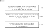
- FIG. 3 is a flowchart showing a method of detecting a lamination defect in an electrode assembly according to the present invention.
- a method for detecting a lamination defect of an electrode assembly includes: forming an insulating member having a predetermined width and a predetermined height in an overhang region of one end or two ends of one surface of a negative electrode (S10); manufacturing an electrode assembly by sequentially laminating a separator and a positive electrode on one surface of the negative electrode (S20); and determining whether there is a lamination defect in the electrode assembly by measuring a thickness of the electrode assembly (S30).
- the overhang region of a negative electrode means a region corresponding to a predetermined width in one end or two ends of a negative electrode.
- the negative electrode covers the positive electrode as the width and length of the negative electrode is set to be greater than the width and length of the positive electrode.
- the overhang region of the negative electrode means the region of the negative electrode where the positive electrode is not included when the negative electrode covers the positive electrode.
- the overhang region of the negative electrode may mean the width of the region where an electrode tab has been arranged or its opposite region.
- the present invention it is possible to determine whether there is a lamination defect in the electrode assembly by forming an insulating member in an overhang region of the negative electrode, and then measuring the thickness of an electrode assembly which is manufactured by sequentially laminating a negative electrode, a separator and a positive electrode.
- the specific method of detecting a lamination defect of an electrode assembly will be described later.
- the method of detecting a lamination defect of an electrode assembly according to the present invention includes forming an insulating member having a predetermined width and a predetermined height in an overhang region of one end of one surface of the negative electrode.
- the insulating member is formed on one surface of the negative electrode using an attaching or coating process, etc.
- the width of the insulating member is in a range of 1 to 500 ⁇ m, 5 to 300 ⁇ m, 10 to 100 ⁇ m, or 10 to 50 11m.
- the height of the insulating member is in a range of 1 to 500 ⁇ m, 5 to 300 ⁇ m, 10 to 100 ⁇ m, or 10 to 40 ⁇ m.
- the width and the height of the insulating member are not limited thereto. The width and the height of the insulating member may be changed according to the structure and the size of the negative electrode and the positive electrode which are laminated at the time of manufacturing an electrode assembly.
- the width of the insulating member when the width of the insulating member is too large, it may be formed to exceed the overhang region of the negative electrode, and thus it is preferable to have an appropriate width. Further, when the height of the insulating member is too large, the height of the insulating member may also be measured even when the electrode assembly is normal. Hence, it is preferable that the height of the insulating member does not exceed the height of the positive electrode or positive electrode active material layer.
- the insulating member is made of an electrically stable material, and in the negative electrode, the region of the insulating member may be a region where the capacity of a normal battery cell is not manifested.
- the insulating member may contain polyethylene, polypropylene, polyetherimide, polyacetal, polysulfone, polyetheretherketone, polyester, polyamide, polystyrene, polyethylene terephthalate, polyphenylene, polytetrafluoroethylene, polysiloxane, polyamide, polyvinylidene fluoride, and a copolymer thereof, or a mixture thereof.
- the insulating member may be formed by coating polyethylene to have a predetermined width and height at the overhang region of one end of a negative electrode.
- a width W1 of the negative electrode except for a region, where the insulating member has been formed may correspond to a width W2 of the positive electrode or may be greater than the width W2 of the positive electrode. This means that the insulating member is located only on an overhang region of the negative electrode.
- the width of the negative electrode is greater than the width of the positive electrode, and in the case that the width W1 of the negative electrode except for the region where the insulating member has been formed is smaller than the width W2 of the positive electrode, the insulating member may be formed to exceed the overhang region of the negative electrode.
- the width W1 of the negative electrode except for the region where the insulating member has been formed is smaller than the width W2 of the positive electrode, if the positive electrode is laminated on the upper portion of the negative electrode, the positive electrode may be laminated on the upper portion of the insulating member, and a lamination defect may occur in the electrode assembly.
- the positive electrode when the positive electrode is laminated on the upper portion of the negative electrode, if one end of the positive electrode is arranged on an overhang region of the negative electrode or is arranged to exceed the overhang region of the negative electrode where an insulating member has been formed, it may be determined that there is a lamination defect in the electrode assembly.
- the method of detecting a lamination defect of an electrode assembly according to the present invention includes forming first and second insulating members in an overhang region of two ends of one surface of the negative electrode.
- an interval L between first and second insulating members may correspond to a width W2 of the positive electrode or may be greater than the width W2 of the positive electrode.
- the interval L between the first and second insulating members means the width of the negative electrode except for the region where the insulating member has been formed.
- the width of the negative electrode is greater than the width of the positive electrode, and in the case that the width W1 of the negative electrode except for the region where the insulating member has been formed is smaller than the width W2 of the positive electrode, the insulating member may be formed to exceed the overhang region of the negative electrode.
- the positive electrode when the positive electrode is laminated on the upper portion of the negative electrode, the positive electrode may be laminated on the upper portion of the insulating member, and the lamination defect may occur in the electrode assembly.
- the positive electrode when the positive electrode is laminated on the upper portion of the negative electrode, if one end of the positive electrode is arranged on an overhang region of the negative electrode or is arranged to exceed the overhang region of the negative electrode where an insulating member has been formed, it may be determined that there is a lamination defect in the electrode assembly.
- a method of detecting a lamination defect of an electrode assembly includes manufacturing an electrode assembly by sequentially laminating a separator and a positive electrode on one surface of a negative electrode having the insulating member formed thereon (S20). Further, it is possible to determine whether there is a lamination defect in the manufactured electrode assembly by measuring the thickness of the manufactured electrode assembly.
- the method of detecting a lamination defect of an electrode assembly according to the present invention includes determining whether there is a lamination defect in the electrode assembly by measuring a thickness of the electrode assembly (S30).
- the determining of whether there is a lamination defect in the electrode assembly includes determining that there is a lamination defect in the electrode assembly if the thickness of the electrode assembly exceeds a sum of each thickness of the negative electrode, the separator, and the positive electrode.
- the negative electrode according to the present invention has an insulating member at the overhang region of one end. When the positive electrode is laminated on the overhang region of the negative electrode active material layer, the positive electrode is laminated on the upper portion of the insulating member. As such, when thickness of the electrode assembly is measured, the thickness of the insulating member may also be measured.
- the thickness of the electrode assembly having a lamination defect may exceed the sum of the thickness of each of the negative electrode, the separator and the positive electrode. Namely, when the thickness of the manufactured electrode assembly exceeds the sum of each thickness of the negative electrode, the separator and the positive electrode, it is determined that there is a lamination defect in the electrode assembly.
- the thickness of each of the negative electrode, the separator and the positive electrode is 80 ⁇ m, 20 ⁇ m, and 100 ⁇ m
- the thickness of the manufactured electrode assembly exceeds 200 ⁇ m, it is determined that that is a lamination defect in the manufactured electrode assembly.
- the determining of whether there is a lamination defect in the electrode assembly includes determining that there is no lamination defect in the electrode assembly if the thickness of the electrode assembly corresponds to a sum of each thickness of the negative electrode, the separator, and the positive electrode. This means that the positive electrode is laminated on the upper portion of the negative electrode, it is laminated on a region where the insulating member has not been formed.
- the thickness of each of the negative electrode, the separator and the positive electrode is 80 ⁇ m, 20 ⁇ m, and 100 ⁇ m
- the thickness of the manufactured electrode assembly is 200 ⁇ m, it is determined that that is no lamination defect in the manufactured electrode assembly.
- the electrode assembly may have a structure including at least one of a bi-cell unit of a positive electrode/ negative electrode/ positive electrode structure, or a mono-cell unit of a positive electrode/ negative electrode structure.
- an electrode assembly may be a mono-cell of a positive electrode/separator/negative electrode, and the mono-cell has a separator interposed between the positive electrode and the negative electrode.
- the separator may have a structure protruding from the positive electrode and the negative electrode because the area of the separator is greater than the area of the positive electrode and the negative electrode.
- the present invention it is possible to easily determine whether there is a lamination defect in the electrode assembly by measuring only the thickness of the laminated electrode assembly.
- the present invention it is possible to measure the thickness of the electrode assembly by only laminating a negative electrode and a positive electrode, and it is possible to easily detect whether there is a lamination defect in an electrode assembly before injecting an electrolyte solution or performing a packaging procedure.
- the present invention provides an electrode assembly. More specifically, the present invention relates to an electrode assembly having a structure including a negative electrode, a positive electrode and a separator between the negative electrode and the positive electrode, in which the negative electrode has a structure having an insulating member having a predetermined width and a predetermined height in an overhang region of one end or two ends of one surface of the negative electrode.
- the negative electrode since the negative electrode includes an insulating member, it is possible to detect a lamination defect in the initial stages at the time of manufacturing an electrode assembly.
- the positive electrode has a structure in which a positive electrode mixture layer is stacked on one or both sides of a positive electrode current collector.
- the positive electrode mixture layer includes a positive electrode active material, a conductive material and a binder polymer, etc. and if necessary, may further include a positive electrode additive commonly used in the art.
- the positive electrode active material may be a lithium-containing oxide, and may be the same or different.
- a lithium-containing transition metal oxide may be used as the lithium-containing oxide.
- the positive electrode according to the present invention can be applied to various types of lithium secondary batteries, but is preferably used for high-power batteries.
- the positive electrode active material layer of the present invention is applied to a high content nickel (High-Ni)-based NCM battery.
- the positive electrode active material layer according to the present invention includes an active material component having a structure represented by Chemical Formula 1 or Chemical Formula 2 below.
- the value "a” is 0.6 or more, specifically 0.8 or more.
- the value “b” and/or value “c” decrease within the range satisfying the above Formula 1.Through this, the positive electrode for a lithium secondary battery according to the present invention is applied to a high-Ni-based NCM secondary battery.
- [Chemical formula 2] Li x (Ni a Co b Mn c Al d )O 2 (In the above chemical formula 2, 0.5 ⁇ x ⁇ 1.3, 0.6 ⁇ a ⁇ 1, 0 ⁇ b ⁇ 0.2, 0 ⁇ c ⁇ 0.1, 0 ⁇ d ⁇ 0.1, and a+b+c+d 1).
- the NCM secondary battery may be, for example, NCM 622, NCM 651520, NCM 712 or NCM 811 (Ni ⁇ 80%).
- the output is high while maintaining stability as in NCM by adding aluminum while not reducing the cobalt ratio.
- the current collector used for the positive electrode is a metal having high conductivity, and any metal which the positive electrode active material slurry may be easily attached to and which is not reactive in the voltage range of the electrochemical device can be used.
- the current collector for the positive electrode include aluminum, nickel, or a foil manufactured by a combination thereof.
- the positive electrode active material may be included in the range of 90.0 to 98.5 wt% in the positive electrode mixture layer.
- the content of the positive electrode active material satisfies the above range, it is advantageous in terms of manufacturing a high-capacity battery and providing sufficient conductivity of the positive electrode or adhesion between electrode materials.
- the current collector used for the positive electrode is a metal having high conductivity, and any metal which the positive electrode active material slurry may be easily attached to and which is not reactive in the voltage range of the secondary battery can be used.
- the current collector for the positive electrode include aluminum, nickel, or a foil manufactured by a combination thereof.
- the positive electrode mixture layer further includes a conductive material.
- the conductive material is usually added in an amount of 1 to 30% by weight based on the total weight of the mixture including the positive electrode active material.
- Such a conductive material is not particularly limited as long as it has conductivity without causing a chemical change in the secondary battery.
- graphite such as natural graphite or artificial graphite
- carbon black such as carbon black, acetylene black, ketjen black, channel black, furnace black, lamp black, or thermal black
- conductive fiber such as carbon fiber or metal fiber
- metal powder such as carbon fluoride, aluminum, or nickel powder
- conductive whiskey such as zinc oxide or potassium titanate
- conductive metal oxide such as titanium oxide
- polyphenylene derivative, and carbon nano tube (CNT) may be used as the conductive material.
- a binder polymer commonly used in the art may be used without limitation.
- various kinds of binders such as polyvinylidene fluoride-co-hexafluoropropylene (PVDF-co-HFP), polyvinylidene fluoride (PVDF), polyacrylonitrile, polymethyl methacrylate, styrene-butadiene rubber (SBR), and carboxyl methyl cellulose (CMC) may be used.
- PVDF-co-HFP polyvinylidene fluoride-co-hexafluoropropylene
- PVDF polyvinylidene fluoride
- SBR styrene-butadiene rubber
- CMC carboxyl methyl cellulose
- the binder polymer content is proportional to the conductive material content included in the positive electrode mixture layer. This is to impart adhesion to conductive materials whose particle size is relatively small compared to the active material and is because when the content of the conductive material increases, more binder polymer is required, and when the content of the conductive material decreases, less binder polymer can be used.
- the negative electrode may include a negative electrode current collector, and a mixture layer of a double layer structure formed on the negative electrode current collector.
- Non-limiting examples of the current collector used for the negative electrode include copper, gold, nickel, or a foil manufactured by a copper alloy or a combination thereof.
- the current collector may be used by stacking substrates made of the above materials.
- the separator may be made of any porous substrate used in a lithium secondary battery, and for example, a polyolefin-based porous membrane or a nonwoven fabric may be used, but the present invention is not particularly limited thereto.
- polystyrene-based porous membrane examples include polyethylene such as high density polyethylene, linear low density polyethylene, low density polyethylene, ultrahigh molecular weight polyethylene, and a membrane in which polyolefin-based polymers, such as polypropylene, polybutylene, or polypentene, are each formed alone or in a mixture thereof.
- polyethylene such as high density polyethylene, linear low density polyethylene, low density polyethylene, ultrahigh molecular weight polyethylene
- polyolefin-based polymers such as polypropylene, polybutylene, or polypentene
- Polyethyleneterephthalate, polybutyleneterephthalate, polyester, polyacetal, polyamide, polycarbonate, polyimide, polyetheretherketone, polyethersulfone, polyphenyleneoxide, polyphenylenesulfide, and polyethylenenaphthalene, etc. may be used individually or as a polymer by a mixture thereof, to thereby form the non-woven fabric, in addition to polyolefin-based nonwoven fabric.
- the structure of the nonwoven fabric may be a spunbonded nonwoven fabric composed of long fibers or a melt blown nonwoven fabric.
- the thickness of the porous substrate is not particularly limited, but may be 5 to 50 ⁇ m, and the pore size and porosity present in the porous substrate are also not particularly limited, but may be 0.01 to 50 ⁇ m and 10 to 95%, respectively.
- a porous coating layer including inorganic particles and a binder polymer may be further included on at least one surface of the porous substrate.
- the electrolyte solution may contain an organic solvent and an electrolyte salt, and the electrolyte salt is a lithium salt.
- Those conventionally used in the electrolyte solution for lithium secondary batteries may be used as the lithium salt without limitation.
- organic solvent included in the electrolyte solution described above those conventionally used in electrolyte solutions for lithium secondary batteries may be used without limitation, and for example, ethers, esters, amides, linear carbonates, and cyclic carbonates may be used alone or in combination of two or more.
- ethers, esters, amides, linear carbonates, and cyclic carbonates may be used alone or in combination of two or more.
- representatively, a cyclic carbonate, a linear carbonate, or a carbonate compound that is a mixture thereof may be included.
- cyclic carbonate compound examples include any one selected from the group consisting of ethylene carbonate (EC), propylene carbonate (PC), 1,2-butylene carbonate, 2,3-butylene carbonate, 1,2-pentylene carbonate, 2,3-pentylene carbonate, vinylene carbonate, vinylethylene carbonate, and a halide thereof, and a mixture thereof.
- halides include, for example, fluoroethylene carbonate (FEC), but are not limited thereto.
- linear carbonate compound examples include any one selected from the group consisting of dimethyl carbonate (DMC), diethyl carbonate (DEC), dipropyl carbonate, ethylmethyl carbonate (EMC), methylpropyl carbonate, and ethylpropyl carbonate, or a mixture of two or more of them may be typically used, but is not limited thereto.
- ethylene carbonate and propylene carbonate which are cyclic carbonates
- any one selected from the group consisting of dimethyl ether, diethyl ether, dipropyl ether, methylethyl ether, methylpropyl ether, and ethylpropyl ether, or a mixture of two or more thereof may be used, but is not limited thereto.
- esters among the organic solvents include any one selected from the group consisting of methyl acetate, ethyl acetate, propyl acetate, methyl propionate, ethyl propionate, propyl propionate, ⁇ -butyrolactone, ⁇ -valerolactone, ⁇ -caprolactone, ⁇ -valerolactone and ⁇ -caprolactone or a mixture of two or more of them, but the present invention is not limited thereto.
- the injection of the non-aqueous electrolyte may be performed at an appropriate step in the manufacturing process of the secondary battery, depending on the manufacturing process and required physical properties of the final product.
- the present invention provides a battery cell including an electrode assembly. If the battery cell is a secondary battery capable of charging and discharging, it is not particularly limited.
- the battery cell may be a pouch-type battery cell or a cylindrical battery cell.
- the battery cell may be a pouch-type battery cell.
- the battery cell is a pouch type unit cell, and an electrode assembly having a positive electrode/ separator/ negative electrode structure is embedded in an exterior material of the laminate sheet in a state that is connected to electrode leads formed outside the exterior material.
- the electrode leads may be drawn to the outside of the sheet and may be extended in the same or opposite direction to each other.
- FIGS. 4 to 5 are cross-sectional views showing a laminated structure of an electrode assembly including an insulating member in one embodiment of the present invention.
- an electrode assembly 120 is manufactured by sequentially laminating a negative electrode 140, a separator 150 and a positive electrode 130.At this time, an insulating member 160 is formed on the overhang region 141 of one end of one surface of the negative electrode 140.
- the width W1 of the negative electrode except for the region where the insulating member 160 has been formed is greater than the width W2 of the positive electrode. Further, when the positive electrode 130 is laminated on the upper portion of the negative electrode 140, if one end of the positive electrode 130 is arranged on an overhang region 141 of the negative electrode 140 or is arranged to exceed the overhang region 141 of the negative electrode 140, it is determined that there is a lamination defect in the electrode assembly 120.
- the thickness of the electrode assembly 120 is measured by measuring the thickness of the region where the insulating member 160 is positioned. Specifically, as illustrated in FIG.
- the thickness of the electrode assembly 120 when measuring the thickness of the electrode assembly 120 which is manufactured by sequentially laminating the negative electrode 140, the separator 150, and the positive electrode 130, the thickness of the electrode assembly becomes 200 ⁇ m.At this time, the thickness of each of the negative electrode 140, the separator 150 and the positive electrode 130 is 80 ⁇ m, 20 ⁇ m and 100 ⁇ m. The thickness of the electrode assembly 120 corresponds to the sum of the thickness of each of the negative electrode 140, the separator 150 and the positive electrode 130. As such, it can be determined that there is no lamination defect in the electrode assembly 120.
- the thickness of the electrode assembly 120 when measuring the thickness of the electrode assembly 120 which is manufactured by sequentially laminating the negative electrode 140, the separator 150, and the positive electrode 130, the thickness of the electrode assembly becomes 220 ⁇ m.At this time, the thickness of each of the negative electrode 140, the separator 150 and the positive electrode 130 is 80 ⁇ m, 20 ⁇ m and 100 ⁇ m.The thickness of the electrode assembly 120 exceeds the sum of the thickness of each of the negative electrode 140, the separator 150 and the positive electrode 130. As such, it can be determined that there is a lamination defect in the electrode assembly 120.
- an insulating member 160 is formed in an overhang region 141 of one end of the negative electrode 140, and the positive electrode 130 is stacked on the overhang region 141 of the negative electrode, and when the thickness of the electrode assembly 120 is measured, the thickness of the insulating member 160 is also measured.As such, the thickness of the electrode assembly 120 may exceed the sum of the thickness of each of the negative electrode 140, the separator 150 and the positive electrode 130.
- the present invention it is possible to easily determine whether there is a lamination defect in the electrode assembly by measuring only the thickness of the laminated electrode assembly.
- FIGS. 6 to 8 are cross-sectional views showing a laminated structure of an electrode assembly including an insulating member in another embodiment of the present invention.
- an electrode assembly 220 is manufactured by sequentially laminating a negative electrode 240, a separator 250 and a positive electrode 230.At this time, first and second insulating members 261 and 262 are formed on the overhang regions 241 and 242 of two ends of one surface of the negative electrode 240.
- an interval L between first and second insulating members 261 and 262 corresponds to a width W2 of the positive electrode or is greater than the width W2 of the positive electrode.
- the thickness of the electrode assembly 220 is measured by measuring the thickness of the region where the insulating member 261, 262 is positioned. Specifically, as illustrated in FIG. 6 , when measuring the thickness of the electrode assembly 220 which is manufactured by sequentially laminating the negative electrode 240, the separator 250, and the positive electrode 230, the thickness of the electrode assembly becomes 200 ⁇ m.
- the thickness of each of the negative electrode 240, the separator 250 and the positive electrode 230 is 80 ⁇ m, 20 ⁇ m and 100 ⁇ m.
- the thickness of the electrode assembly 220 corresponds to the sum of the thickness of each of the negative electrode 240, the separator 250 and the positive electrode 230. As such, it can be determined that there is no lamination defect in the electrode assembly 220.
- the thickness of the electrode assembly 220 when measuring the thickness of the electrode assembly 220 which is manufactured by sequentially laminating the negative electrode 240, the separator 250, and the positive electrode 230, the thickness of the electrode assembly becomes 220 ⁇ m.At this time, the thickness of each of the negative electrode 240, the separator 250 and the positive electrode 230 is 80 ⁇ m, 20 ⁇ m and 100 ⁇ m. The thickness of the electrode assembly 220 exceeds the sum of the thickness of each of the negative electrode 240, the separator 250 and the positive electrode 230. As such, it can be determined that there is a lamination defect in the electrode assembly 220.
- an insulating member 261 is formed in an overhang region 241 of one end of the negative electrode 240, and the positive electrode 230 is stacked on the overhang region 241 of the negative electrode, and when the thickness of the electrode assembly 220 is measured, the thickness of the insulating member 261 is also measured. As such, the thickness of the electrode assembly 220 may exceed the sum of the thickness of each of the negative electrode 240, the separator 250 and the positive electrode 230.
- an insulating member 262 is formed in an overhang region 242 of the other end of the negative electrode 240, and the positive electrode 230 is stacked on the overhang region 242 of the negative electrode, and when the thickness of the electrode assembly 220 is measured, the thickness of the insulating member 262 is also measured.As such, the thickness of the electrode assembly 220 may exceed the sum of the thickness of each of the negative electrode 240, the separator 250 and the positive electrode 230.
- the thickness of the electrode assembly 220 when measuring the thickness of the electrode assembly 220 which is manufactured by sequentially laminating the negative electrode 240, the separator 250, and the positive electrode 230, the thickness of the electrode assembly becomes 220 ⁇ m.
- the thickness of the electrode assembly 220 exceeds the sum of the thickness of each of the negative electrode 240, the separator 250 and the positive electrode 230. As such, it can be determined that there is a lamination defect in the electrode assembly 220.
- the present invention it is possible to easily determine whether there is a lamination defect in the electrode assembly by measuring only the thickness of the laminated electrode assembly.
Landscapes
- Engineering & Computer Science (AREA)
- Manufacturing & Machinery (AREA)
- Chemical & Material Sciences (AREA)
- Chemical Kinetics & Catalysis (AREA)
- Electrochemistry (AREA)
- General Chemical & Material Sciences (AREA)
- Physics & Mathematics (AREA)
- General Physics & Mathematics (AREA)
- Secondary Cells (AREA)
- Connection Of Batteries Or Terminals (AREA)
- Battery Electrode And Active Subsutance (AREA)
- Testing Of Short-Circuits, Discontinuities, Leakage, Or Incorrect Line Connections (AREA)
Claims (10)
- Verfahren zum Erkennen eines Laminierungsfehlers einer Elektrodenanordnung (12, 120, 220), wobei das Verfahren umfasst:Ausbilden eines isolierenden Elements (160) mit einer vorbestimmten Breite und einer vorbestimmten Höhe in einem Überhangbereich eines Endes oder zweier Enden einer Oberfläche einer negativen Elektrode (14, 140, 240);Herstellen einer Elektrodenanordnung durch aufeinanderfolgendes Laminieren eines Separators (15, 150, 250) und einer positiven Elektrode (13, 130, 230) auf die eine Oberfläche der negativen Elektrode (14, 140, 240); undBestimmen, ob es einen Laminierungsfehler in der Elektrodenanordnung (12, 120, 220) gibt, durch Messen einer Dicke eines Bereichs, in dem das isolierende Element auf der Elektrodenanordnung (12, 120, 220) angeordnet ist.
- Verfahren nach Anspruch 1, wobei das Ausbilden des isolierenden Elements (160) das Ausbilden des isolierenden Elements (160) in dem Überhangbereich eines Endes der einen Oberfläche der negativen Elektrode (14, 140, 240) enthält.
- Verfahren nach Anspruch 1, wobei eine Breite W1 der negativen Elektrode (14, 140, 240) mit Ausnahme eines Bereichs, in dem das isolierende Element (160) ausgebildet wurde, einer Breite W2 der positiven Elektrode (13, 130, 230) entspricht oder größer ist als die Breite W2 der positiven Elektrode (13, 130, 230).
- Verfahren nach Anspruch 1, wobei das Ausbilden des isolierenden Elements (160) das Ausbilden eines ersten und eines zweiten isolierenden Elements (261, 262) im Überhangbereich zweier Enden der einen Oberfläche der negativen Elektrode (14, 140, 240) enthält.
- Verfahren nach Anspruch 4, wobei ein Abstand L zwischen dem ersten und dem zweiten isolierenden Element (261, 262) einer Breite W2 der positiven Elektrode (13, 130, 230) entspricht oder größer ist als die Breite W2 der positiven Elektrode (13, 130, 230).
- Verfahren nach Anspruch 1, wobei das Bestimmen, ob ein Laminierungsfehler in der Elektrodenanordnung (12, 120, 220) vorliegt, das Bestimmen beinhaltet, dass ein Laminierungsfehler in der Elektrodenanordnung (12, 120, 220) vorliegt, wenn die Dicke der Elektrodenanordnung (12, 120, 220) eine Summe jeder Dicke der negativen Elektrode (14, 140, 240), des Separators (15, 150, 250) und der positiven Elektrode (13, 130, 230) überschreitet.
- Verfahren nach Anspruch 1, wobei das Bestimmen, ob ein Laminierungsfehler in der Elektrodenanordnung (12, 120, 220) vorliegt, das Bestimmen beinhaltet, dass kein Laminierungsfehler in der Elektrodenanordnung (12, 120, 220) vorliegt, wenn die Dicke der Elektrodenanordnung (12, 120, 220) einer Summe jeder Dicke der negativen Elektrode (14, 140, 240), des Separators (15, 150, 250) und der positiven Elektrode (13, 130, 230) entspricht.
- Verfahren nach Anspruch 1, wobei die Elektrodenanordnung (12, 120, 220) eine Struktur aufweist, die mindestens eine Zweizelleneinheit einer positive Elektrode (13, 130, 230)/negative Elektrode (14, 140, 240)/positive Elektrode (13, 130, 230)-Struktur oder eine Einzelleneinheit einer positive Elektrode (13, 130, 230)/negative Elektrode (14, 140, 240)-Struktur beinhaltet.
- Elektrodenanordnung (12, 120, 220) mit einer Struktur, die eine negative Elektrode (14, 140, 240), eine positive Elektrode (13, 130, 230) und einen Separator (15, 150, 250) zwischen der negativen Elektrode (14, 140, 240) und der positiven Elektrode (13, 130, 230) enthält,
wobei die negative Elektrode (14, 140, 240) eine Struktur mit einem isolierenden Element (160) mit einer vorbestimmten Breite und einer vorbestimmten Höhe in einem Überhangbereich eines Endes oder zweier Enden einer Oberfläche der negativen Elektrode (14, 140, 240) beinhaltet. - Batteriezelle (10), welche die Elektrodenanordnung (12, 120, 220) nach Anspruch 9 enthält.
Applications Claiming Priority (2)
| Application Number | Priority Date | Filing Date | Title |
|---|---|---|---|
| KR1020200129936A KR102900615B1 (ko) | 2020-10-08 | 2020-10-08 | 전극조립체의 적층 불량 검출 방법, 절연 부재를 포함하는 전극조립체 및 이를 포함하는 전지 셀 |
| PCT/KR2021/012953 WO2022075637A1 (ko) | 2020-10-08 | 2021-09-23 | 전극조립체의 적층 불량 검출 방법, 절연 부재를 포함하는 전극조립체 및 이를 포함하는 전지 셀 |
Publications (3)
| Publication Number | Publication Date |
|---|---|
| EP4044307A1 EP4044307A1 (de) | 2022-08-17 |
| EP4044307A4 EP4044307A4 (de) | 2024-06-19 |
| EP4044307B1 true EP4044307B1 (de) | 2025-05-21 |
Family
ID=81125854
Family Applications (1)
| Application Number | Title | Priority Date | Filing Date |
|---|---|---|---|
| EP21877889.2A Active EP4044307B1 (de) | 2020-10-08 | 2021-09-23 | Verfahren zur stapelfehlerdetektion bei einer elektrodenanordnung, elektrodenanordnung mit einem isolierenden element und batteriezelle damit |
Country Status (8)
| Country | Link |
|---|---|
| US (1) | US12272794B2 (de) |
| EP (1) | EP4044307B1 (de) |
| JP (1) | JP7493735B2 (de) |
| KR (1) | KR102900615B1 (de) |
| CN (1) | CN114651356B (de) |
| ES (1) | ES3034397T3 (de) |
| HU (1) | HUE072040T2 (de) |
| WO (1) | WO2022075637A1 (de) |
Families Citing this family (6)
| Publication number | Priority date | Publication date | Assignee | Title |
|---|---|---|---|---|
| KR102900615B1 (ko) * | 2020-10-08 | 2025-12-15 | 주식회사 엘지에너지솔루션 | 전극조립체의 적층 불량 검출 방법, 절연 부재를 포함하는 전극조립체 및 이를 포함하는 전지 셀 |
| WO2023210941A1 (ko) * | 2022-04-25 | 2023-11-02 | 주식회사 엘지에너지솔루션 | 전극 조립체 및 이를 포함하는 전지셀 |
| KR102667112B1 (ko) * | 2022-04-25 | 2024-05-17 | 컨템포러리 엠퍼렉스 테크놀로지 씨오., 리미티드 | 배터리 극편의 오버행 검출 방법, 장치, 설비, 저장 매체 |
| KR102608580B1 (ko) * | 2022-12-27 | 2023-12-01 | 율촌화학 주식회사 | 웰 검출을 통한 셀타입 전지 파우치용 필름의 성형 깊이 한계 설정 방법 |
| CN120604375A (zh) * | 2023-11-20 | 2025-09-05 | 株式会社Lg新能源 | 最外层负极的去活化方法、电极组件的制造方法和电极组件 |
| JP2026501902A (ja) * | 2023-11-20 | 2026-01-16 | エルジー エナジー ソリューション リミテッド | 最外郭負極の不活性化方法、電極アセンブリの製造方法及び電極アセンブリ |
Family Cites Families (33)
| Publication number | Priority date | Publication date | Assignee | Title |
|---|---|---|---|---|
| JPS60212430A (ja) | 1984-04-06 | 1985-10-24 | Seitetsu Kagaku Co Ltd | ポリオレフインの微粉末化方法 |
| JP4986450B2 (ja) | 2005-12-27 | 2012-07-25 | 日本ゴア株式会社 | 識別マークを有する膜電極接合体およびそれを用いた固体高分子電解質型燃料電池の製造方法 |
| CN101971407B (zh) * | 2009-05-11 | 2013-05-22 | 丰田自动车株式会社 | 固体电池的制造方法和固体电池 |
| JP2011039014A (ja) | 2009-08-06 | 2011-02-24 | Toshiba It & Control Systems Corp | 電池検査装置 |
| CN105186028B (zh) | 2010-02-23 | 2017-08-04 | Tdk株式会社 | 电化学装置以及电化学装置的制造方法 |
| JP6024629B2 (ja) | 2013-09-12 | 2016-11-16 | トヨタ自動車株式会社 | 膜電極接合体および燃料電池の製造方法 |
| US10290903B2 (en) * | 2013-11-12 | 2019-05-14 | Lg Chem, Ltd. | Jellyroll-type electrode assembly and secondary battery comprising the same |
| WO2015080305A1 (ko) * | 2013-11-27 | 2015-06-04 | 주식회사 엘지화학 | 전극조립체 및 이를 포함하는 전기화학소자 |
| JP6350909B2 (ja) | 2014-06-30 | 2018-07-04 | エリーパワー株式会社 | 電極積層体のセパレータの位置ずれ検出方法およびその装置 |
| KR101735157B1 (ko) | 2014-07-24 | 2017-05-12 | 주식회사 엘지화학 | 전극 조립체 및 이를 포함하는 이차전지 |
| KR101729815B1 (ko) | 2014-07-29 | 2017-04-24 | 주식회사 엘지화학 | 전극 조립체 및 이를 위한 기본 단위체 |
| JP6327101B2 (ja) * | 2014-10-09 | 2018-05-23 | 株式会社豊田自動織機 | 電極組立体の製造装置および電極組立体の製造方法 |
| CN106033823B (zh) * | 2015-03-11 | 2018-11-13 | 北京好风光储能技术有限公司 | 一种注液量可控的高电压动力电池及其制备方法 |
| KR20170024498A (ko) * | 2015-08-25 | 2017-03-07 | 주식회사 엘지화학 | 전극조립체의 불량 검출장치 |
| JP6372453B2 (ja) | 2015-09-07 | 2018-08-15 | トヨタ自動車株式会社 | 積層電極体の製造方法 |
| WO2017043178A1 (ja) | 2015-09-09 | 2017-03-16 | ソニー株式会社 | 二次電池 |
| JP6589663B2 (ja) | 2016-01-28 | 2019-10-16 | 株式会社村田製作所 | 検査方法、積層型電池の製造方法、検査装置、および積層型電池の製造装置 |
| JP6703416B2 (ja) | 2016-02-18 | 2020-06-03 | 積水化学工業株式会社 | リチウムイオン二次電池及びリチウムイオン二次電池の検査方法 |
| KR102055721B1 (ko) | 2016-04-22 | 2019-12-13 | 주식회사 엘지화학 | 전극 조립체의 두께 측정 장치 및 전극 조립체의 두께 측정 방법 |
| KR102217447B1 (ko) * | 2017-07-06 | 2021-02-22 | 주식회사 엘지화학 | 이차전지 |
| CN111373595A (zh) * | 2017-11-21 | 2020-07-03 | 丰田自动车株式会社 | 全固体电池用电极体及其制造方法 |
| KR102403813B1 (ko) | 2018-01-10 | 2022-05-30 | 주식회사 엘지에너지솔루션 | 기본단위체 제조방법 및 그를 포함하는 전극조립체 제조방법 |
| KR102287768B1 (ko) | 2018-01-29 | 2021-08-10 | 주식회사 엘지에너지솔루션 | 전극 조립체 제조방법 및 이차전지 제조방법 |
| JP7116632B2 (ja) | 2018-08-22 | 2022-08-10 | 株式会社豊田自動織機 | 蓄電モジュール |
| KR102177841B1 (ko) * | 2018-11-22 | 2020-11-11 | 주식회사 강한이노시스 | 조명을 이용한 2차전지 전극 적층 감시 장치 |
| JP7117554B2 (ja) | 2018-11-27 | 2022-08-15 | パナソニックIpマネジメント株式会社 | 積層型電池の検査装置 |
| JP7068632B2 (ja) * | 2018-12-11 | 2022-05-17 | トヨタ自動車株式会社 | 電池 |
| KR102644980B1 (ko) | 2018-12-14 | 2024-03-08 | 주식회사 엘지에너지솔루션 | 전극 조립체 정렬 불량 판단 장치 및 방법 |
| KR102107226B1 (ko) * | 2018-12-20 | 2020-05-07 | 김태완 | 적층 전지 정렬 검사 장치 |
| KR102849372B1 (ko) | 2019-03-28 | 2025-08-25 | 주식회사 엘지에너지솔루션 | 전극 조립체 제조방법 및 전극 조립체 제조장치 |
| KR102223509B1 (ko) | 2019-05-10 | 2021-03-05 | 주식회사 바디프랜드 | 출수부 모듈이 이동하는 경우 유로가 유지되는 수처리 장치 |
| KR102858853B1 (ko) * | 2020-03-11 | 2025-09-11 | 주식회사 엘지에너지솔루션 | 이차전지 및 이의 리튬 석출 검출 방법 |
| KR102900615B1 (ko) * | 2020-10-08 | 2025-12-15 | 주식회사 엘지에너지솔루션 | 전극조립체의 적층 불량 검출 방법, 절연 부재를 포함하는 전극조립체 및 이를 포함하는 전지 셀 |
-
2020
- 2020-10-08 KR KR1020200129936A patent/KR102900615B1/ko active Active
-
2021
- 2021-09-23 EP EP21877889.2A patent/EP4044307B1/de active Active
- 2021-09-23 JP JP2022526272A patent/JP7493735B2/ja active Active
- 2021-09-23 WO PCT/KR2021/012953 patent/WO2022075637A1/ko not_active Ceased
- 2021-09-23 HU HUE21877889A patent/HUE072040T2/hu unknown
- 2021-09-23 US US17/775,678 patent/US12272794B2/en active Active
- 2021-09-23 CN CN202180006251.9A patent/CN114651356B/zh active Active
- 2021-09-23 ES ES21877889T patent/ES3034397T3/es active Active
Also Published As
| Publication number | Publication date |
|---|---|
| KR20220046821A (ko) | 2022-04-15 |
| JP2023501418A (ja) | 2023-01-18 |
| WO2022075637A1 (ko) | 2022-04-14 |
| EP4044307A1 (de) | 2022-08-17 |
| CN114651356A (zh) | 2022-06-21 |
| CN114651356B (zh) | 2024-08-20 |
| HUE072040T2 (hu) | 2025-10-28 |
| JP7493735B2 (ja) | 2024-06-03 |
| KR102900615B1 (ko) | 2025-12-15 |
| EP4044307A4 (de) | 2024-06-19 |
| US20220376305A1 (en) | 2022-11-24 |
| ES3034397T3 (en) | 2025-08-18 |
| US12272794B2 (en) | 2025-04-08 |
Similar Documents
| Publication | Publication Date | Title |
|---|---|---|
| EP4044307B1 (de) | Verfahren zur stapelfehlerdetektion bei einer elektrodenanordnung, elektrodenanordnung mit einem isolierenden element und batteriezelle damit | |
| KR102160701B1 (ko) | 천공 구조의 집전체를 포함하는 전극, 이를 포함하는 리튬 이차전지 | |
| KR101621410B1 (ko) | 리튬 전극 및 그를 포함하는 리튬 이차전지 | |
| KR101621412B1 (ko) | 리튬 전극 및 그를 포함하는 리튬 이차전지 | |
| KR102238829B1 (ko) | 리튬 금속 이차전지 및 이를 포함하는 전지모듈 | |
| KR102865847B1 (ko) | 전기화학소자용 전극 및 이를 구비한 전기화학소자 | |
| KR102244904B1 (ko) | 전극 보호층을 포함하는 음극 및 이를 적용한 리튬 이차전지 | |
| KR101684347B1 (ko) | 최외각면에 절연성 물질이 부가되어 있는 전극조립체 및 이를 포함하는 이차전지 | |
| EP3836254B1 (de) | Sekundärbatteriekathode mit verbesserter wärmestabilität und herstellungsverfahren dafür | |
| CN110622342B (zh) | 一种制造包括锂电极的锂金属二次电池的方法 | |
| KR101620617B1 (ko) | 도전성이 개선된 양극 합제, 그를 구비하는 양극 및 전기화학소자 | |
| KR102207527B1 (ko) | 전극 보호층을 포함하는 음극 및 이를 적용한 리튬 이차전지 | |
| KR20170011357A (ko) | 다공성 리튬전극과 그 제조방법 및 이를 이용한 리튬 이차전지 | |
| KR102730072B1 (ko) | 파우치형 이차전지의 제조방법 | |
| US12315910B2 (en) | Device for pre-lithiation of negative electrode and method for pre-lithiation of negative electrode | |
| KR20250085695A (ko) | 젤리롤 전극 조립체 및 이를 포함하는 원통형 리튬 이차 전지 | |
| KR20210018164A (ko) | 리튬 금속 이차전지 및 그를 포함하는 전지모듈 | |
| KR101288907B1 (ko) | 리튬 이차전지 | |
| KR20180127759A (ko) | 리튬 이차전지용 세퍼레이터 및 그를 포함하는 리튬 이차전지 | |
| US20240162446A1 (en) | An Electrode for an Electrochemical Device and an Electrochemical Device Comprising the Same | |
| KR20220037294A (ko) | 단락 발생에 따른 발화 모사를 위한 테스트 셀 및 이를 이용한 단락 발생에 따른 발화 모사 방법 | |
| KR20170009097A (ko) | 도전성이 개선된 양극 및 그를 포함하는 전기화학소자 | |
| EP3902034B1 (de) | Anode mit mehreren parallel nebeneinander angeordneten stromkollektoren und diese enthaltende sekundärbatterie |
Legal Events
| Date | Code | Title | Description |
|---|---|---|---|
| STAA | Information on the status of an ep patent application or granted ep patent |
Free format text: STATUS: THE INTERNATIONAL PUBLICATION HAS BEEN MADE |
|
| PUAI | Public reference made under article 153(3) epc to a published international application that has entered the european phase |
Free format text: ORIGINAL CODE: 0009012 |
|
| STAA | Information on the status of an ep patent application or granted ep patent |
Free format text: STATUS: REQUEST FOR EXAMINATION WAS MADE |
|
| 17P | Request for examination filed |
Effective date: 20220510 |
|
| AK | Designated contracting states |
Kind code of ref document: A1 Designated state(s): AL AT BE BG CH CY CZ DE DK EE ES FI FR GB GR HR HU IE IS IT LI LT LU LV MC MK MT NL NO PL PT RO RS SE SI SK SM TR |
|
| DAV | Request for validation of the european patent (deleted) | ||
| DAX | Request for extension of the european patent (deleted) | ||
| A4 | Supplementary search report drawn up and despatched |
Effective date: 20240516 |
|
| RIC1 | Information provided on ipc code assigned before grant |
Ipc: H01M 10/48 20060101ALN20240511BHEP Ipc: H01M 10/052 20100101ALN20240511BHEP Ipc: G01B 21/08 20060101ALI20240511BHEP Ipc: H01M 10/0585 20100101ALI20240511BHEP Ipc: H01M 10/04 20060101AFI20240511BHEP |
|
| GRAP | Despatch of communication of intention to grant a patent |
Free format text: ORIGINAL CODE: EPIDOSNIGR1 |
|
| STAA | Information on the status of an ep patent application or granted ep patent |
Free format text: STATUS: GRANT OF PATENT IS INTENDED |
|
| RIC1 | Information provided on ipc code assigned before grant |
Ipc: H01M 10/48 20060101ALN20250305BHEP Ipc: H01M 10/052 20100101ALN20250305BHEP Ipc: G01B 21/08 20060101ALI20250305BHEP Ipc: H01M 10/0585 20100101ALI20250305BHEP Ipc: H01M 10/04 20060101AFI20250305BHEP |
|
| GRAS | Grant fee paid |
Free format text: ORIGINAL CODE: EPIDOSNIGR3 |
|
| INTG | Intention to grant announced |
Effective date: 20250317 |
|
| GRAA | (expected) grant |
Free format text: ORIGINAL CODE: 0009210 |
|
| STAA | Information on the status of an ep patent application or granted ep patent |
Free format text: STATUS: THE PATENT HAS BEEN GRANTED |
|
| P01 | Opt-out of the competence of the unified patent court (upc) registered |
Free format text: CASE NUMBER: APP_16840/2025 Effective date: 20250407 |
|
| AK | Designated contracting states |
Kind code of ref document: B1 Designated state(s): AL AT BE BG CH CY CZ DE DK EE ES FI FR GB GR HR HU IE IS IT LI LT LU LV MC MK MT NL NO PL PT RO RS SE SI SK SM TR |
|
| REG | Reference to a national code |
Ref country code: GB Ref legal event code: FG4D |
|
| REG | Reference to a national code |
Ref country code: CH Ref legal event code: EP |
|
| REG | Reference to a national code |
Ref country code: DE Ref legal event code: R096 Ref document number: 602021031274 Country of ref document: DE |
|
| REG | Reference to a national code |
Ref country code: IE Ref legal event code: FG4D |
|
| REG | Reference to a national code |
Ref country code: ES Ref legal event code: FG2A Ref document number: 3034397 Country of ref document: ES Kind code of ref document: T3 Effective date: 20250818 |
|
| REG | Reference to a national code |
Ref country code: NL Ref legal event code: MP Effective date: 20250521 |
|
| PG25 | Lapsed in a contracting state [announced via postgrant information from national office to epo] |
Ref country code: PT Free format text: LAPSE BECAUSE OF FAILURE TO SUBMIT A TRANSLATION OF THE DESCRIPTION OR TO PAY THE FEE WITHIN THE PRESCRIBED TIME-LIMIT Effective date: 20250922 Ref country code: FI Free format text: LAPSE BECAUSE OF FAILURE TO SUBMIT A TRANSLATION OF THE DESCRIPTION OR TO PAY THE FEE WITHIN THE PRESCRIBED TIME-LIMIT Effective date: 20250521 |
|
| PGFP | Annual fee paid to national office [announced via postgrant information from national office to epo] |
Ref country code: DE Payment date: 20250820 Year of fee payment: 5 |
|
| REG | Reference to a national code |
Ref country code: LT Ref legal event code: MG9D |
|
| PG25 | Lapsed in a contracting state [announced via postgrant information from national office to epo] |
Ref country code: NO Free format text: LAPSE BECAUSE OF FAILURE TO SUBMIT A TRANSLATION OF THE DESCRIPTION OR TO PAY THE FEE WITHIN THE PRESCRIBED TIME-LIMIT Effective date: 20250821 Ref country code: GR Free format text: LAPSE BECAUSE OF FAILURE TO SUBMIT A TRANSLATION OF THE DESCRIPTION OR TO PAY THE FEE WITHIN THE PRESCRIBED TIME-LIMIT Effective date: 20250822 |
|
| PG25 | Lapsed in a contracting state [announced via postgrant information from national office to epo] |
Ref country code: PL Free format text: LAPSE BECAUSE OF FAILURE TO SUBMIT A TRANSLATION OF THE DESCRIPTION OR TO PAY THE FEE WITHIN THE PRESCRIBED TIME-LIMIT Effective date: 20250521 Ref country code: NL Free format text: LAPSE BECAUSE OF FAILURE TO SUBMIT A TRANSLATION OF THE DESCRIPTION OR TO PAY THE FEE WITHIN THE PRESCRIBED TIME-LIMIT Effective date: 20250521 |
|
| PG25 | Lapsed in a contracting state [announced via postgrant information from national office to epo] |
Ref country code: BG Free format text: LAPSE BECAUSE OF FAILURE TO SUBMIT A TRANSLATION OF THE DESCRIPTION OR TO PAY THE FEE WITHIN THE PRESCRIBED TIME-LIMIT Effective date: 20250521 |
|
| PGFP | Annual fee paid to national office [announced via postgrant information from national office to epo] |
Ref country code: HU Payment date: 20250929 Year of fee payment: 5 Ref country code: BE Payment date: 20250820 Year of fee payment: 5 Ref country code: GB Payment date: 20250820 Year of fee payment: 5 |
|
| PG25 | Lapsed in a contracting state [announced via postgrant information from national office to epo] |
Ref country code: HR Free format text: LAPSE BECAUSE OF FAILURE TO SUBMIT A TRANSLATION OF THE DESCRIPTION OR TO PAY THE FEE WITHIN THE PRESCRIBED TIME-LIMIT Effective date: 20250521 |
|
| PGFP | Annual fee paid to national office [announced via postgrant information from national office to epo] |
Ref country code: FR Payment date: 20250821 Year of fee payment: 5 Ref country code: AT Payment date: 20251020 Year of fee payment: 5 |
|
| PG25 | Lapsed in a contracting state [announced via postgrant information from national office to epo] |
Ref country code: RS Free format text: LAPSE BECAUSE OF FAILURE TO SUBMIT A TRANSLATION OF THE DESCRIPTION OR TO PAY THE FEE WITHIN THE PRESCRIBED TIME-LIMIT Effective date: 20250821 |
|
| PG25 | Lapsed in a contracting state [announced via postgrant information from national office to epo] |
Ref country code: IS Free format text: LAPSE BECAUSE OF FAILURE TO SUBMIT A TRANSLATION OF THE DESCRIPTION OR TO PAY THE FEE WITHIN THE PRESCRIBED TIME-LIMIT Effective date: 20250921 |
|
| REG | Reference to a national code |
Ref country code: HU Ref legal event code: AG4A Ref document number: E072040 Country of ref document: HU |
|
| PG25 | Lapsed in a contracting state [announced via postgrant information from national office to epo] |
Ref country code: LV Free format text: LAPSE BECAUSE OF FAILURE TO SUBMIT A TRANSLATION OF THE DESCRIPTION OR TO PAY THE FEE WITHIN THE PRESCRIBED TIME-LIMIT Effective date: 20250521 |
|
| REG | Reference to a national code |
Ref country code: AT Ref legal event code: MK05 Ref document number: 1797588 Country of ref document: AT Kind code of ref document: T Effective date: 20250521 |
|
| PG25 | Lapsed in a contracting state [announced via postgrant information from national office to epo] |
Ref country code: DK Free format text: LAPSE BECAUSE OF FAILURE TO SUBMIT A TRANSLATION OF THE DESCRIPTION OR TO PAY THE FEE WITHIN THE PRESCRIBED TIME-LIMIT Effective date: 20250521 Ref country code: AT Free format text: LAPSE BECAUSE OF FAILURE TO SUBMIT A TRANSLATION OF THE DESCRIPTION OR TO PAY THE FEE WITHIN THE PRESCRIBED TIME-LIMIT Effective date: 20250521 Ref country code: SM Free format text: LAPSE BECAUSE OF FAILURE TO SUBMIT A TRANSLATION OF THE DESCRIPTION OR TO PAY THE FEE WITHIN THE PRESCRIBED TIME-LIMIT Effective date: 20250521 |
|
| PG25 | Lapsed in a contracting state [announced via postgrant information from national office to epo] |
Ref country code: CZ Free format text: LAPSE BECAUSE OF FAILURE TO SUBMIT A TRANSLATION OF THE DESCRIPTION OR TO PAY THE FEE WITHIN THE PRESCRIBED TIME-LIMIT Effective date: 20250521 |
|
| PG25 | Lapsed in a contracting state [announced via postgrant information from national office to epo] |
Ref country code: EE Free format text: LAPSE BECAUSE OF FAILURE TO SUBMIT A TRANSLATION OF THE DESCRIPTION OR TO PAY THE FEE WITHIN THE PRESCRIBED TIME-LIMIT Effective date: 20250521 |
|
| PG25 | Lapsed in a contracting state [announced via postgrant information from national office to epo] |
Ref country code: SK Free format text: LAPSE BECAUSE OF FAILURE TO SUBMIT A TRANSLATION OF THE DESCRIPTION OR TO PAY THE FEE WITHIN THE PRESCRIBED TIME-LIMIT Effective date: 20250521 |
|
| PG25 | Lapsed in a contracting state [announced via postgrant information from national office to epo] |
Ref country code: IT Free format text: LAPSE BECAUSE OF FAILURE TO SUBMIT A TRANSLATION OF THE DESCRIPTION OR TO PAY THE FEE WITHIN THE PRESCRIBED TIME-LIMIT Effective date: 20250521 |
|
| PGFP | Annual fee paid to national office [announced via postgrant information from national office to epo] |
Ref country code: ES Payment date: 20251007 Year of fee payment: 5 |
|
| PG25 | Lapsed in a contracting state [announced via postgrant information from national office to epo] |
Ref country code: RO Free format text: LAPSE BECAUSE OF FAILURE TO SUBMIT A TRANSLATION OF THE DESCRIPTION OR TO PAY THE FEE WITHIN THE PRESCRIBED TIME-LIMIT Effective date: 20250521 |
|
| REG | Reference to a national code |
Ref country code: DE Ref legal event code: R097 Ref document number: 602021031274 Country of ref document: DE |
|
| PLBE | No opposition filed within time limit |
Free format text: ORIGINAL CODE: 0009261 |
|
| STAA | Information on the status of an ep patent application or granted ep patent |
Free format text: STATUS: NO OPPOSITION FILED WITHIN TIME LIMIT |
|
| REG | Reference to a national code |
Ref country code: CH Ref legal event code: L10 Free format text: ST27 STATUS EVENT CODE: U-0-0-L10-L00 (AS PROVIDED BY THE NATIONAL OFFICE) Effective date: 20260402 |
|
| 26N | No opposition filed |
Effective date: 20260224 |